

Page 1

Table of Contents
Section Page Number
Preface
Chapter 1 Introducing the Terminal Server 720
1.1 About the Terminal Server 720..........................................................8
1.2 Controls and Indicators..................................................................11
1.3 Product Prerequisites....................................................................12
1.3.1 Changing the Software Loading Method......................................12
1.4 Parameter Storage and Loading........................................................13
Chapter 2 Installation Notes
2.1 Prepare for the Installation..............................................................14
2.2 Unpack and Inspect the Terminal Server.............................................14
2.3 Install the Terminal Server and I/O Card ............................................15
2.4 Connect the Device Cables...............................................................15
2.5 Install the Memory Card - If Available................................................16
2.6 Initialize the Terminal Server 720.....................................................17
2.7 Initialize Connected Serial Devices ...................................................20
Chapter 3 I/O and Cabling Considerations
3.1 Overview to Cabling......................................................................21
3.2 RJ-45 Cabling Options...................................................................23
3.2.1 Making Your Own RJ-45 Cables...............................................23
3.2.2 Device Wiring Considerations................................................24
3.2.3 Modular Adaptors ...............................................................25
3.2.4 DECconnect RJ-45 Cables.......................................................28
3.2.5 Octopus Cables ...................................................................29
3.3 Telco Cabling Options ...................................................................31
3.3.1 Rear Panel Connection (Telco)................................................31
3.3.2 Extension Cables ................................................................33
3.3.3 Octopus Cables ...................................................................34
3.3.4 Distribution Panels .............................................................35
3.3.5 Modular Splitters................................................................37
3.3.6 Modular Cables..................................................................37
3.3.7 Punch Down Block ..............................................................38
3.3.8 Gender Changer.................................................................40
3.3.9 DECconnect™ 36-Pin Serial Interface Connections........................40
3.3.10 DECconnect Adaptor Cables....................................................40
3.3.11 DECconnect Style Modular Splitters ..........................................41
3.3.12 Device Wiring Considerations (Telco).......................................42
Page 2

Table of Contents (continued)
Section Page Number
Chapter 4 Operation and Software Configuration
4.1 Introduction...............................................................................43
4.2 Logging On to a Port and Obtaining Help.............................................43
4.3 Configuring TCP/IP Characteristics..................................................44
4.4 Becoming a Privileged User............................................................44
4.5 Assigning an Internet Address.........................................................45
4.6 Configuring Domain Name Server Support...........................................46
4.7 Summary of Internet-Related Commands............................................48
Chapter 5 Memory Upgrades
Appendix A Specifications
Appendix B Order Codes
B.1 Processor and I/O Module Order Codes................................................56
B.2 Model 723 I/O Module Cabling Order Codes...........................................56
B.3 Model 721 I/O Module Cabling Order Codes...........................................58
Appendix C Configuration Menu
C.1 Overview ..................................................................................60
C.2 How to Bring Up the Configuration Menu .............................................63
C.3 Terminal Server Configuration Menu Options ......................................65
C.3.1 Option 1 - Display Configuration..............................................66
C.3.2 Option 2 - Modify Unit Configuration.........................................68
C.3.3 Option 3 - Initialize server and port parameters.............................76
C.3.4 Option 4 - Revert to stored configuration......................................76
C.3.5 Option S - Exit Saving Configuration Changes..............................77
C.3.6 Option X - Exit Without Saving Configuration Changes....................77
Appendix D Trouble Analysis
D.1 Overview..................................................................................78
D.2 Normal Terminal Server Operations.................................................78
D.3 Startup Error Codes.......................................................................80
D.4 Loading Messages........................................................................83
D.4.1 Example Network Load Procedure.....................................................83
D.5 Resetting the terminal server...........................................................85
D.6 If the Ethernet Segment (A, B, or C) Light Is Out ......................................86
D.7 Server Problem Analysis................................................................87
D.8 Overview to Troubleshooting Internet Loading Problems...........................95
D.9 Troubleshooting RARP Problems......................................................96
D.10 Troubleshooting BOOTP Problems ....................................................98
D.11 Troubleshooting TFTP Problems ......................................................99
D.12 Troubleshooting TFTP Directory or File Problems..................................100
Index
Page 3
Preface
How To Use This Guide
This Guide is intended to be used in series with other Xyplex product documentation. This set
of documentation is organized to make the installation of Network 9000 products easy, and to
help you get started using the Terminal Server 720 in the shortest possible time. The following
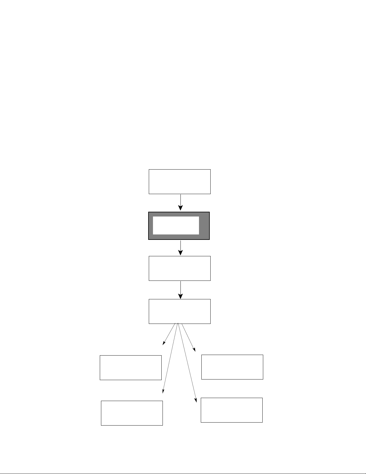
documentation map shows the order in which you should use various Xyplex documentation.
The shaded block indicates where this Guide fits in the installation process.
Network 9000™ Documentation Map
Chassis Installation
Hardware Installation,
Software Installation
Guidelines, Initialization
Configuration Menu
Software Installation on Host
Systems or MAXman Card;
Copying and Formatting of
Memory Cards
Operational Management
of the Chassis and the
Power Supplies.
Managing terminal
servers for the
network administrator
Installing the Network 9000™
Intra-Networking Hub
Getting Started with the
Terminal Server 720
Software Installation Guides
for UNIX, VAX/VMS,
MAXman Cards, and
Memory Cards
Managing Network 9000
Modules and Power Supplies
Detailed descriptions of each
TCP/IP-LAT Terminal Server
Command
TCP/IP-LAT Software
Management Guide
Using terminal servers for
the end-user
Using the TCP-IP LAT
Terminal Server
TCP/IP-LAT Commands
Reference Guide
Syntax of each Terminal
Server Command
TCP/IP-LAT Commands Mini
Reference
5
Page 4

What this Guide Covers
This Getting Started Guide covers installation of the Xyplex Terminal Server 720 processor
module and the available I/O modules and cabling options.
This guide is organized as follows:
Chapter 1 Introducing the Terminal Server 720
Chapter 2 Installation Notes
Chapter 3 I/O and Cabling Considerations
Chapter 4 Operation and Software Configuration
Chapter 5 Memory Upgrades
Appendix A Specifications
Appendix B Order Codes
Appendix C Configuration Menu
Appendix D Trouble Analysis
Index
Chapter 1: Introduction, provides a brief overview of the features and options available with the
Terminal Server 720 and the typical applications (for example, types of devices one could
connect to the unit) of the product. This chapter also covers product prerequisites, such as which
software release is required in order to use the product, and shows the location and purpose of
the controls and indicators on the unit.
Chapter 2: Installation Notes, describes installation issues that are specific to the Terminal
Server 720, including making sure that software is loaded on the unit in order to complete the
installation.
Chapter 3: I/O and Cabling, describes the available I/O module(s) and cables.
Chapter 4: Operation and Software Configuration, describes some of the important software-
related activities that you will need to perform in order to use the Terminal Server 720. These
include how you become a privileged user, how to configure the terminal server Internet
networking configuration, and how to format and update a memory card.
Chapter 5: Memory Upgrades, shows where Terminal Server 720 SIMM sockets are located.
Appendix A: Technical Specifications
Appendix B: Order Codes
6
Page 5

Appendix C: Configuration Menu, explains the purpose of the Configuration Menu (which is to
create and manage load/dump configurations), and describes how to use the initialization
configuration menu to perform the following tasks:
• Select and view the protocols for image and parameter loading, and dumping
(create load/dump configurations)
• Specify information for directed TFTP loading
• Select a network segment
• Initialize parameters
• Revert to stored configuration
• Revert to factory defaults
• Enable display of load status messages
• Configure memory
• Exit
Appendix D: Troubleshooting, describes what to do if you encounter a problem during
installation or server operation. This appendix explains how the terminal server indicates
self-test errors, how to reset the unit, and possible solutions to problems you might encounter
when using the unit.
7
Page 6
Chapter 1
CARD RUN CON
C
.....................................................................................................................................................
2 345 6 71
8
A B
Introducing the Terminal Server 720
1.1 About the Terminal Server 720
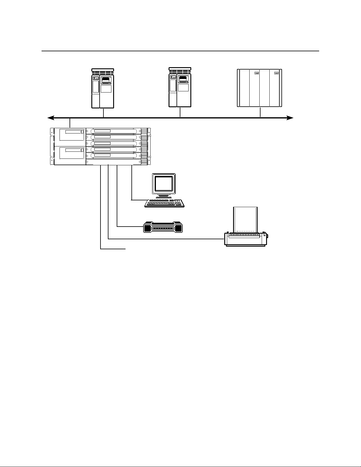
The Terminal Server 720 is an option for the Network 9000 Intra-Networking Hub. The
Terminal Server 720 provides a method of connecting asynchronous serial devices such as
terminals, personal computers, and modems to the network, so that users can connect to
VAX/VMS®host computers, UNIX® host computers, and IBM host computers that support
TN3270. Serial printers can also be connected to the server's serial ports, which allows them to
be shared among multiple hosts, personal computers, or file servers on a network. Figure 1-1
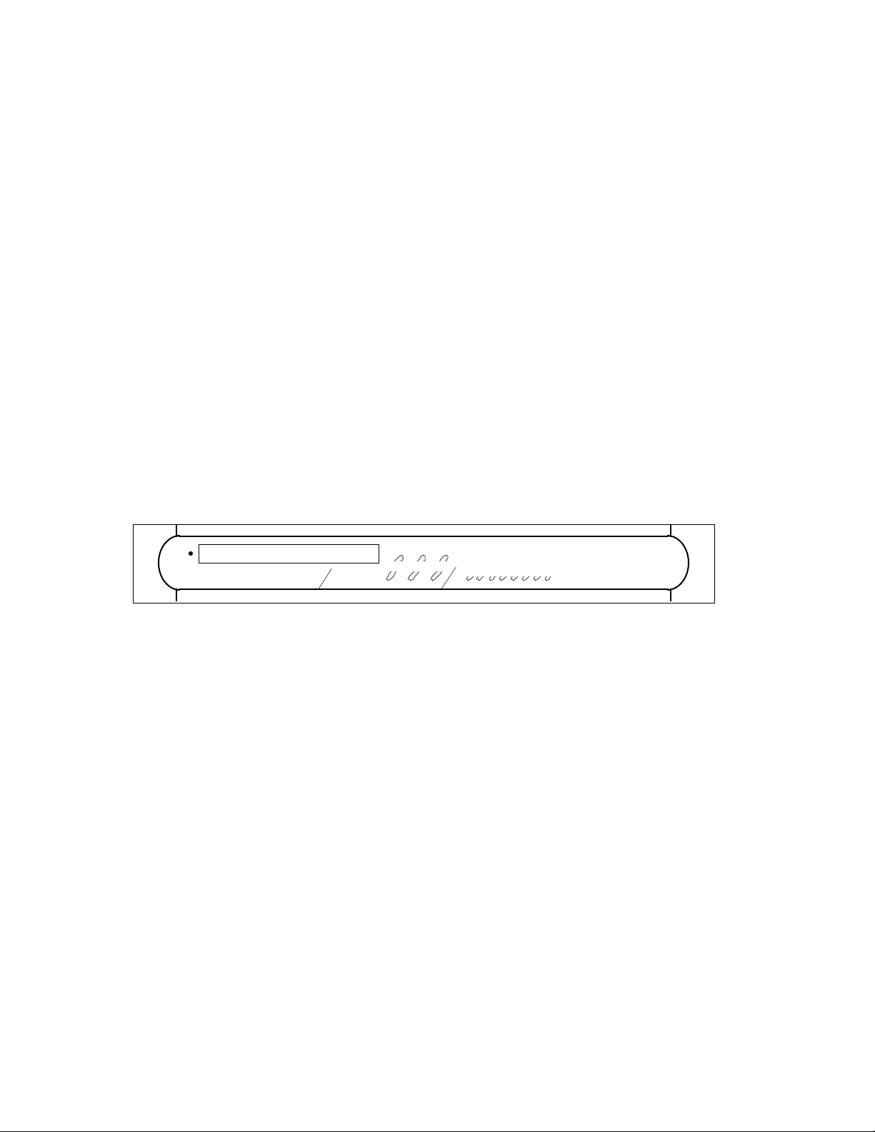
shows a front view of the processor module. Figure 1-2 shows the Terminal Server 720
networking environment.
TERMINAL SERVER 720
ETHERNET
Figure 1-1. Terminal Server 720 Module Front View.
The following are some of the key features of the Terminal Server 720:
Designed for Ease of Start-up -- The Terminal Server 720 includes factory defaults for
operation which allow you to get the unit running easily after hardware installation. Refer to
section 2.6.1 for a description of the default activity of the Terminal Server 720.
TCP/IP-LAT and TN3270 Support -- Concurrent support for TCP/IP, DEC Local Area
Transport (LAT®), and TN3270 protocols.
Expandable Memory -- The server is shipped with 2 MB of factory installed base memory. A 2
MB unit can be expanded to 4 MB, using two 1 MB SIMM memory modules.
Memory Card -- An optional memory card, from which the unit can load its operating software.
“Flash” memory cards are available from Xyplex. These memory cards are
readable/writeable, can be updated with a newer software version, and can store parameters
0021 1-8
Page 7

Introducing the Terminal Server 720
Serial Port I/O and Cabling Options -- There are three serial I/O and cabling schemes
available for the Terminal Server 720.
- Model 721 16-port I/O module. Two 50-pin TELCO connectors provide six-wire
connections for sixteen serial devices, using a variety of wiring schemes, such as
extension cables, distribution panels. splitters, octopus cables, punch-down blocks,
modular (MODtap™) cabling, and DECconnect™ cabling. These ports support
modem control signals and communication speeds from 75 bps to 115.2 Kbps.
- Model 723 20-port I/O module. Twenty RJ-45 connectors provide eight-wire
connections for twenty serial devices using modular cabling. These ports support
modem control and concurrent hardware flow control, and communication speeds
from 75 bps to 115.2 Kbps.
- Model 724 24-port I/O module. Three 50-pin TELCO connectors provide six-wire
connections for twenty-four serial devices, using the same wiring schemes available
for the Model 721 I/O module. These ports support modem control signals and
communication speeds from 75 bps to 115.2 Kbps.
☞ When using port speeds higher than 64 kbps, you must be careful to use a cabling
scheme that minimizes the potential for "cross-talk" problems. Cabling
methods, such as punch-down blocks used in conjunction with bundled 50-wire
cables can suffer from cross-talk at these data rates. It is recommended that you
use separate shielded cables for each port (for example, a Xyplex octopus cable),
when using the TELCO I/O modules, or short cable lengths.
Network Software Loading -- If you order a server without a memory card, the unit loads its
operating software from a network host called a load server. The load server is typically a
UNIXTM or VAX/VMSTM system, a Xyplex loader (a MAXman unit, for example), or a Network
9000 product equipped with a memory card. The load server downloads a software image to the
server, over the network, whenever the server is powered on or re-initialized. The load server
can support other types of Xyplex devices as well.
0021 1-9
Page 8
Introducing the Terminal Server 720
Network 9000
Terminal
Servers
Other Serial Devices Including:
• Xwindows Terminals
• Personal Computers
• Barcode readers
• Controllers
• Point-of-sale equipment
etc
VAX/VMS Host System
UNIX Host System
Terminals
Modems
IBM Host System
Ethernet LAN
1-10 0021
Serial Printers
Figure 1-2. Network Using a Terminal Server 720 Unit.
Page 9
Introducing the Terminal Server 720
CARD RUN CON
C
Serial Port
Status Lights
Ethernet Segment
Indicator Lights
Memory Card Drive Status Light
720 Card Status Light
Console Port Status Light
Reset Switch
.....................................................................................................................................................
2 3 4 5 6 71 8
A B
Memory Card Eject Button
1.2 Controls and Indicators
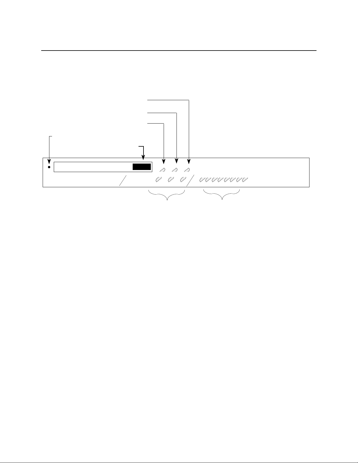
Figure 1-3 shows the location and purpose of all controls and LED indicators on the Terminal
Server 720 cards.
Memory Card Slot
TERMINAL SERVER 720 ETHERNET
Figure 1-3. Terminal Server 720 Controls and Indicators.
0021 1-11
Page 10

Introducing the Terminal Server 720
1.3 Product Prerequisites
The Terminal Server 720 processor module and associated I/O modules can be ordered as part
of a Network 9000 chassis configuration, or can be added separately to an installed Network
9000 unit. Each Terminal Server 720 processor module requires one Network 9000 chassis
processor module slot. Each associated I/O module requires one Network 9000 chassis I/O
module slot.
The server requires Xyplex TCP/IP-LAT software, Release 4.3 or greater. The unit is
configured at the factory to load its software from a memory card, if one is inserted in the card
slot. If a card is not present, the unit requests software from a network load server, which can be:
• Another Terminal Server 720 or other Network 9000 product that is equipped with a
memory card which contains the correct load image.
• A VAX/VMS system, from which the unit can load via DEC Maintenance Operations
Protocol (MOP)
• A UNIX system running:
- Bootstrap protocol (BOOTP) and Trivial File Transfer Protocol (TFTP), or:
- Reverse Address Resolution Protocol (RARP) and TFTP, or
- Trivial File Transfer Protocol (for "Directed" TFTP)
• Other Xyplex loader units, such as a MAXman unit.
The load server sends a software image to the server, over the network, whenever the unit is
powered on or re-initialized. By default, the terminal server requests software from each type
of load server, until a load server responds with a load offer. (Appendix C includes a flow chart
showing the order in which the unit uses protocols to load. Appendix D provides a description of
the software loading process.) You can have multiple load servers on the network.
1.3.1 Changing the Software Loading Method
You can specify the protocols which the server uses to load software and which protocols will be
used. For example, you can configure the unit to load exclusively from a specific type of load
server, to use a specific protocol first and another next, or you can configure the unit to load
from the memory card only. You use the initialization configuration menu (refer to Appendix
C) to change the software loading method. Alternatively, you can use DEFINE CHASSIS
commands to change the software loading method (refer to the Guide to Managing Network
9000 Devices and Power Supplies for more information).
1-12 0021
Page 11

Introducing the Terminal Server 720
1.4 Parameter Storage and Loading
The Terminal Server 720 uses and stores two sets of parameters: the "initialization
parameters" and the permanent "operational parameters."
Initialization parameters refer to values that the Network 9000 unit uses during the software
loading process. Initialization parameters include which protocols should be used to load
software and operational parameters. These parameters are stored in the Control Storage of
the AC input module of the Network 9000 chassis (the Ethernet address of the chassis slot is also
stored there, although the unit cannot alter this). You can change most of these parameters via
a unit's initialization configuration menu (refer to Appendix C for more information) or by
the commands listed in the Guide to Managing Network 9000 Devices and Power Supplies.
Operational parameters (e.g., those affected by DEFINE or SET commands) affect the
operation of the software after initialization. Typically, operational parameters affect serial
ports (e.g., speed, parity, character size, etc), the availability of local services, Internet
characteristics (e.g., internet-address, domain-name, subnet-mask, etc), and LAT
characteristics, etc. You can configure the unit to load its operational parameters from a flash
memory card (not supported on OTP cards), if one is available, or from a network host, called
a parameter server, using the initialization configuration menu (refer to Appendix C for more
information). Alternatively, you can use DEFINE CHASSIS commands to change the
parameter loading method (refer to the Guide to Managing Network 9000 Devices and Power
Supplies for more information).
The Terminal Server 720 is configured at the factory to store parameters locally on a flash
memory card, if one is available, on the memory card of another unit in the hub acting as a
parameter server, or remotely in a file at any properly configured parameter server. You use
commands to change the parameter storing method. Operational parameters can be stored
redundantly so that if one parameter server is not available during a reboot other parameter
servers may be used.
Some units, including the Terminal Server 720, support the use of two sets of operational
parameters. One set is "permanent" the other "temporary." The permanent parameters are
stored at parameter servers or on a flash memory card. You use DEFINE and PURGE
commands to change these parameters, and LIST commands to view information about them.
The temporary parameters are not stored. You use SET and CLEAR commands to change
these parameters, and SHOW or MONITOR commands to view information about them.
Temporary parameters are only in effect until the next time the unit is reinitialized, a port is
logged out, changed with another SET or CLEAR command, or the unit "learns" information
from the network which overrides an existing temporary parameter.
☞ The term operational parameters is used in this guide to refer to parameters which
affect the operation of the software after initialization. Readers of the TCP/IP-LAT
Documentation Set should note that the term operational parameters is used there to
refer only to the set of temporary parameters (mentioned above).
0021 1-13
Page 12

Chapter 2
Installation Notes
2.1 Prepare for the Installation
☞ Before you begin the installation of the Terminal Server 720 processor module and
an I/O module, you must have completed the installation procedure for the Network
9000 Chassis. If this has not been completed, refer to the guide Installing the
Network 9000 Chassis.
Make sure that you have the following items:
Software at a load server or a Memory Card -- The Terminal Server 720 terminal
server can load software locally from a memory card, or remotely from a network load
server. If the unit will load software from a load server, you should make sure that you
have installed software at the load server(s) before you install the hardware. You
should follow the installation and configuration instructions contained in the Software
Installation Guide supplied with your software kit. Load image names will be listed in
the Software Kit Information supplied with your kit. (The Terminal Server 720 has a
hardware type of 76.)
Serial device cables -- Should be available for connection to the terminal server.
- Refer to Chapter 3 for serial device cabling considerations.
Terminal -- You need a VT100 or ANSI-compatible terminal, or a PC with terminal
emulation software in order to configure the Terminal Server 720 terminal server.
Tools -- You need a small Phillips-head screwdriver to secure modules in a Network
9000 chassis slot.
2.2 Unpack and Inspect the Terminal Server
Follow these steps:
1. Carefully unpack the terminal server shipping carton(s).
2. Inspect the contents and make sure that you received all parts listed on the shipping order.
Each terminal server is shipped with the basic items listed in Table 2-1. If any item is
missing, contact Xyplex or the distributor where you bought the unit.
0021 2-14
Page 13

Installation Notes
Table 2-1. Items Supplied with Terminal Server 720
Item Quantity
Terminal Server 720 processor module 1
Sixteen-Port I/O module (model 721), 1
Twenty-Port I/O module (model 723) or
Twenty-four-Port I/O module (model 724)
Terminal Server 720 Getting Started Guide 1
(this manual)
3. Place all packing materials back into the shipping carton and save the carton. (If you need
to return the terminal server to Xyplex or your distributor, you should return it in the
original carton.)
4. If the terminal server has been damaged in shipping or any parts are missing, notify your
Xyplex representative or distributor immediately.
2.3 Install the Terminal Server and I/O Card
Network 9000 processor and I/O modules are very easy to install. If you have previously
installed a Network 9000 processor or I/O module, simply locate an empty slot in the Network
9000 chassis and use the same procedure to install the Terminal Server 720 processor and I/O
modules. (Slot 1 cannot be used for a Terminal Server 720.) If you have not previously
installed a processor and I/O module in the chassis, refer to the instructions contained in
Chapter 4 of the guide Installing the Network 9000 Chassis.
2.4 Connect the Device Cables
Connect the serial device cables to the connectors on the I/O module. While this activity can be
completed at any time during or after the installation process, you will need to have one
terminal connected to a serial port in order to configure the server software. Refer to Chapter 3
for cabling options.
0021 2-15
Page 14
Installation Notes
2.5 Install the Memory Card - If Available
If the Terminal Server 720 is equipped with a memory card, insert the memory card into
the card slot on the front of the unit.
☞ Xyplex recommends that you wear the grounded wrist strap, supplied with the
Network 9000 chassis when you insert the card. If it is not available, ground
yourself by placing one hand on the Network 9000 chassis (or another grounded
object) before you insert the Memory card, to avoid discharging static electricity into
the Terminal Server 720.
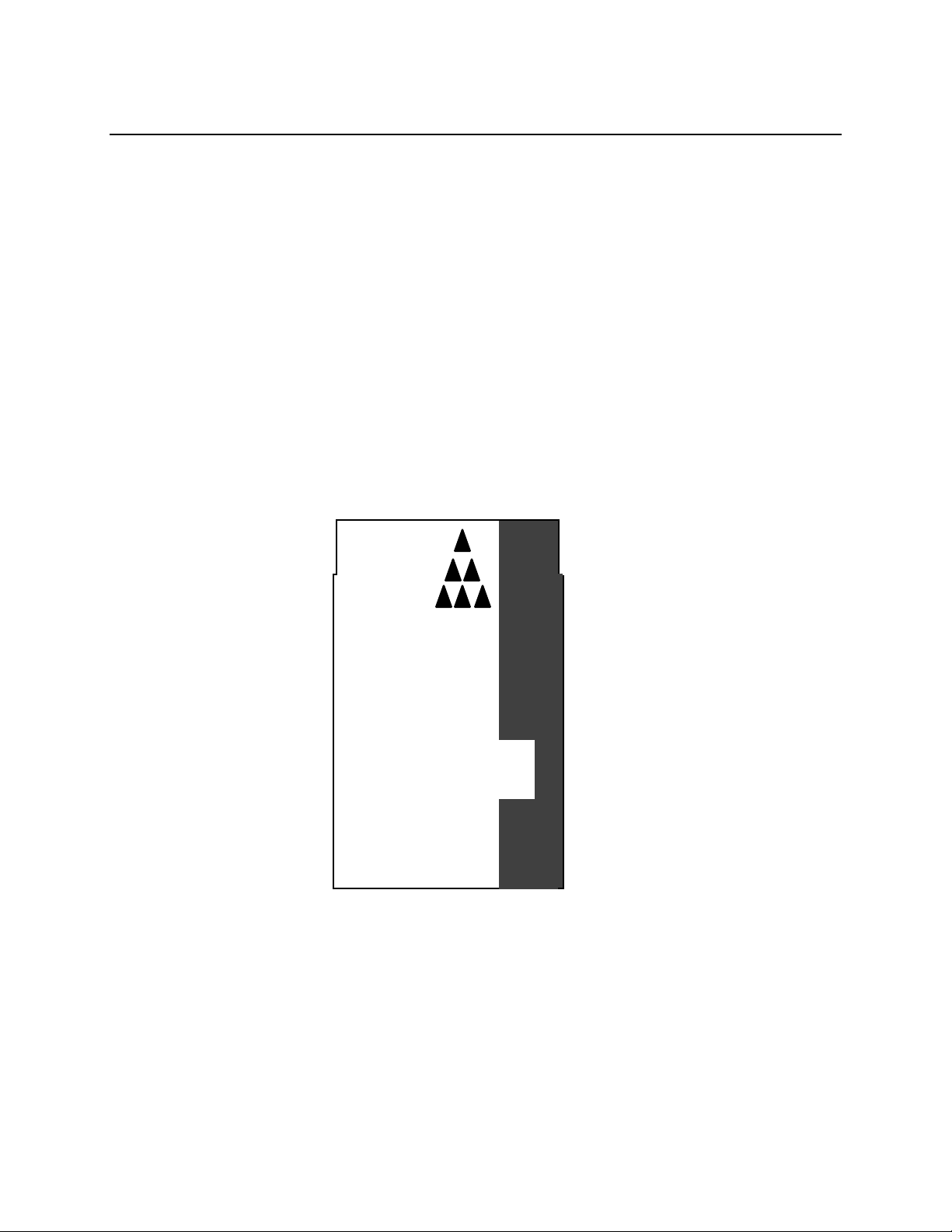
Markings on the memory card indicate which end you insert into the Terminal Server 720
(insert the end which has two rows of small square holes). You can eject the memory card by
pressing the Eject Button. Figure 2-1 shows which end of the memory card to insert into the
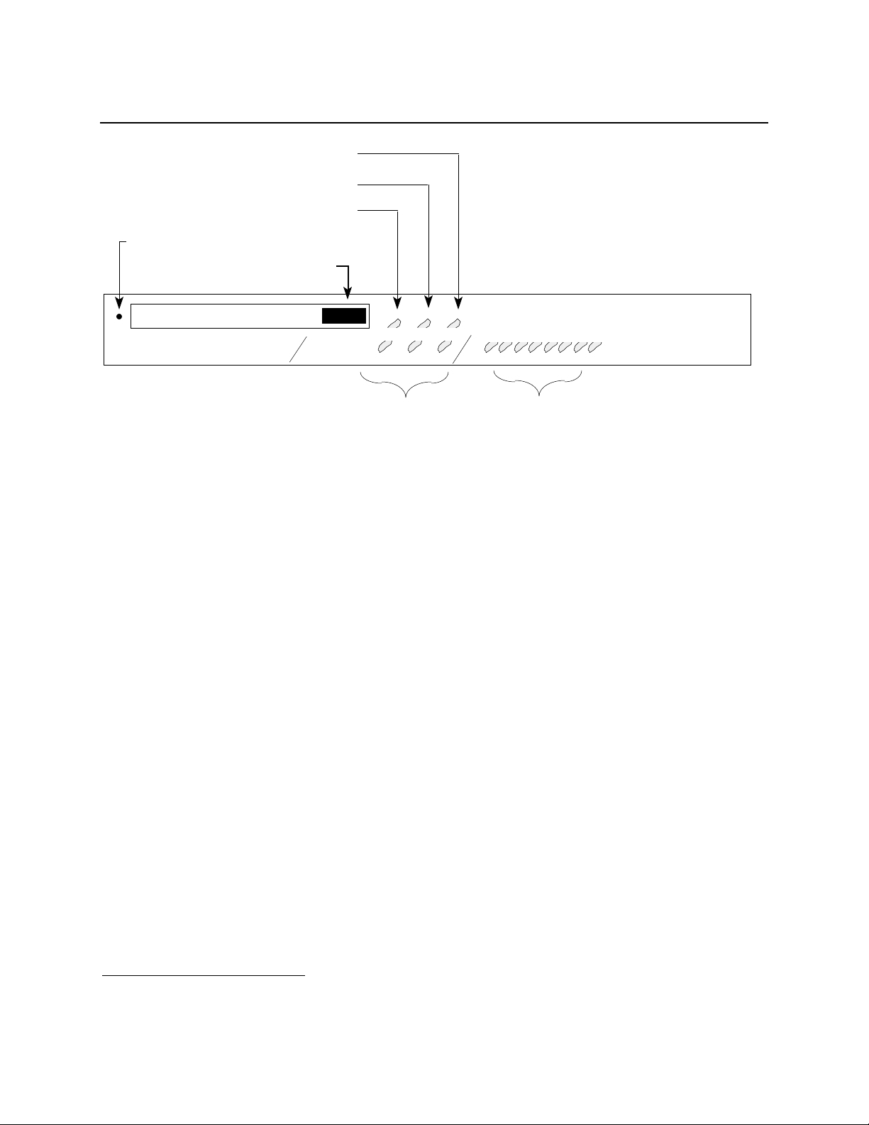
Memory Card Slot. Figure 2-2 shows the location of the Memory Card Slot and Eject Button.
Insert this end.
XYPLEX
Memory
Card
Figure 2-1. Memory Card.
2-16 0021
Page 15
Installation Notes
CARD RUN CON
C
Serial Port
Status Lights
Ethernet Segment
Indicator Lights
Memory Card Drive Status Light
720 Card Status Light
Console Port Status Light
Reset Switch
.....................................................................................................................................................
2 3 4 5 6 71 8
A B
Memory Card Eject Button
Memory Card Slot
TERMINAL SERVER 720 ETHERNET
Figure 2-2. Terminal Server 720 Controls.
The serial port status lights shown in Figure 2-2 are used in several ways. During the
initialization process, the lights indicate that self-tests are being performed, and if any selftest fails, they indicate an error code. After the unit has been received a load image and
parameters, the lights indicate when a port is actively being used. In this case, each light can
indicate activity for more than one port. For example, if LED 1 is lit, this can indicate that
there is activity on ports 1, 9, or 17. LED 2 indicates activity on ports 2, 10, or 18, etc.
1
2.6 Initialize the Terminal Server 720
When you apply power to the Network 9000 Chassis, all modules in the chassis, including
Terminal Server 720 units initialize themselves and begin to try to load software and
operational parameters. If you have installed the Terminal Server 720 into an already
functional Network 9000 Hub, you may need to reset the unit manually, as described below.
The unit is configured at the factory to use a default set of initialization parameters in order to
obtain a software image. This means that, for most configurations, the unit should be able to be
loaded without any configuration changes. Loading is made particularly easy if you have
inserted a memory card which contains the appropriate load image into the Memory Card Slot,
since the unit will load from the memory card. If a card is not present or the appropriate image
is not on the card, the unit requests to be loaded by a host system that has the TCP/IP-LAT
software installed, or a Network 9000 module that has a Memory card which contains the
appropriate load image. (By default, network load requests are transmitted on midplane
Ethernet LAN segment A.) The unit is also configured at the factory to store parameters
locally on a flash memory card, if one is installed, and remotely at properly configured
parameter servers.
1
Each LED indicates port activity on the same numbered port (ports 1 through 8 are shown by LEDs 1 through 8,
respectively) and those ports whose numbers are multiples of 8 added to the LED number
0021 2-17
Page 16
Installation Notes
To reset the terminal server manually, follow these steps:
1. Make a simple "tool" from an ordinary paper clip by bending one end outward. You
need this tool to press the RESET switch located behind the terminal server's front
panel.
2. Look for the small hole to the left of the Memory Card Slot (see Figure 2-2).
3. Use the paper clip tool to press the RESET switch once. This halts all terminal server
operations -- the server will no longer send or receive network data or data from its
connected devices. The terminal server enters a halt state; all front panel lights
illuminate.
☞ All ongoing sessions and data are lost when you reset the unit.
4. Press the RESET switch again. The terminal server performs a self test of its
circuitry, which takes about 20 seconds. Check the lights on the front panel (see Figure
2-2) while the test is under way.
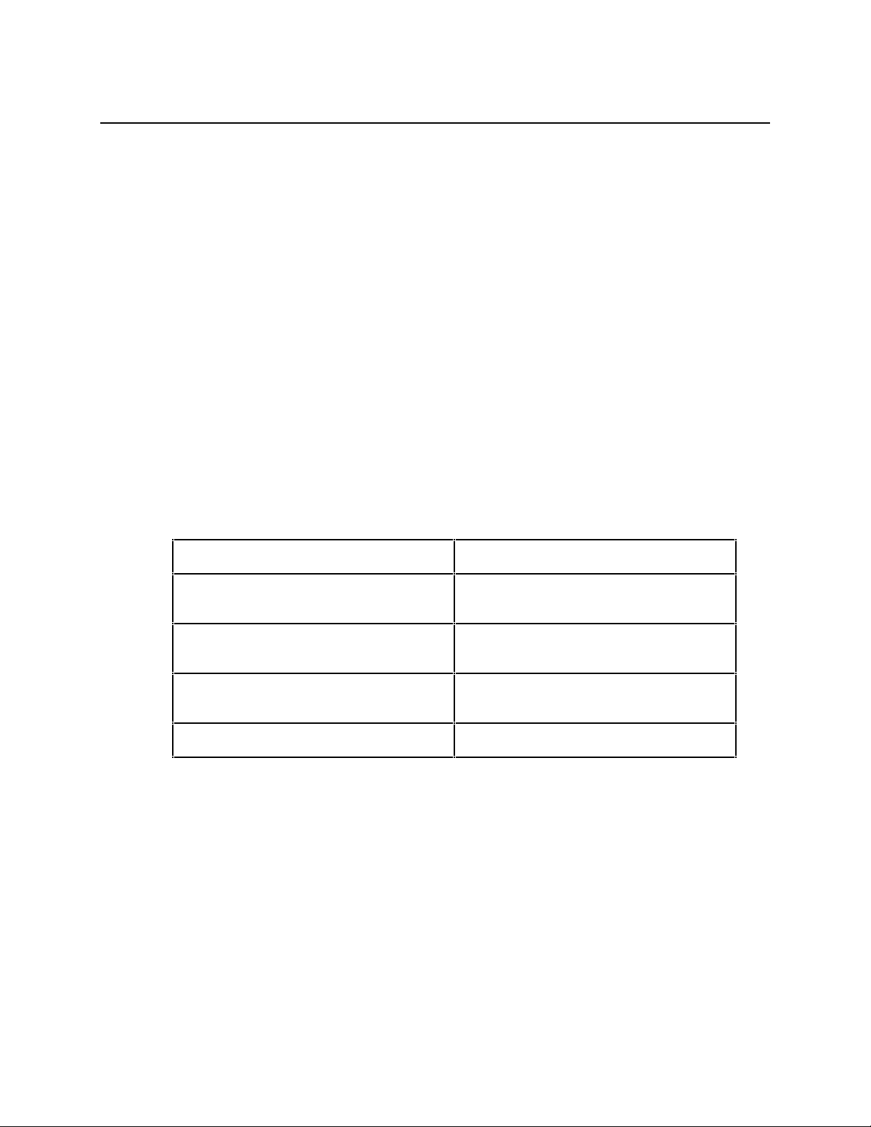
Regardless of how the unit is reset, the light pattern should appear as follows during the self test:
Front Panel Light Activity Meaning
All lights ON Testing lights (approximately 1
second).
CARD, RUN, CON, A, B, and C
(Ethernet) lights OFF
Lights ON, from right (8 status light) to
left (1 status light)
RUN flashes rapidly Successful completion of Self Test.
If the lights do not behave as indicated, refer to the Appendix D. When the Self Test completes,
the terminal server requests load service or begins loading software.
An Ethernet (A, B, or C) LED on the front panel (see Figure 2-2) illuminates as soon as the
terminal server detects network activity (normally about 2 seconds). Within 15 seconds the
unit transmits software load requests on the network or begins to load from the memory card.
The RUN and Ethernet (A, B, or C) LEDs blink during loading. Loading takes from 10 to 60
seconds, depending on whether you are loading from a local memory card, or if from a network
load server, on the amount of network activity and the speed of the load server. The light pattern
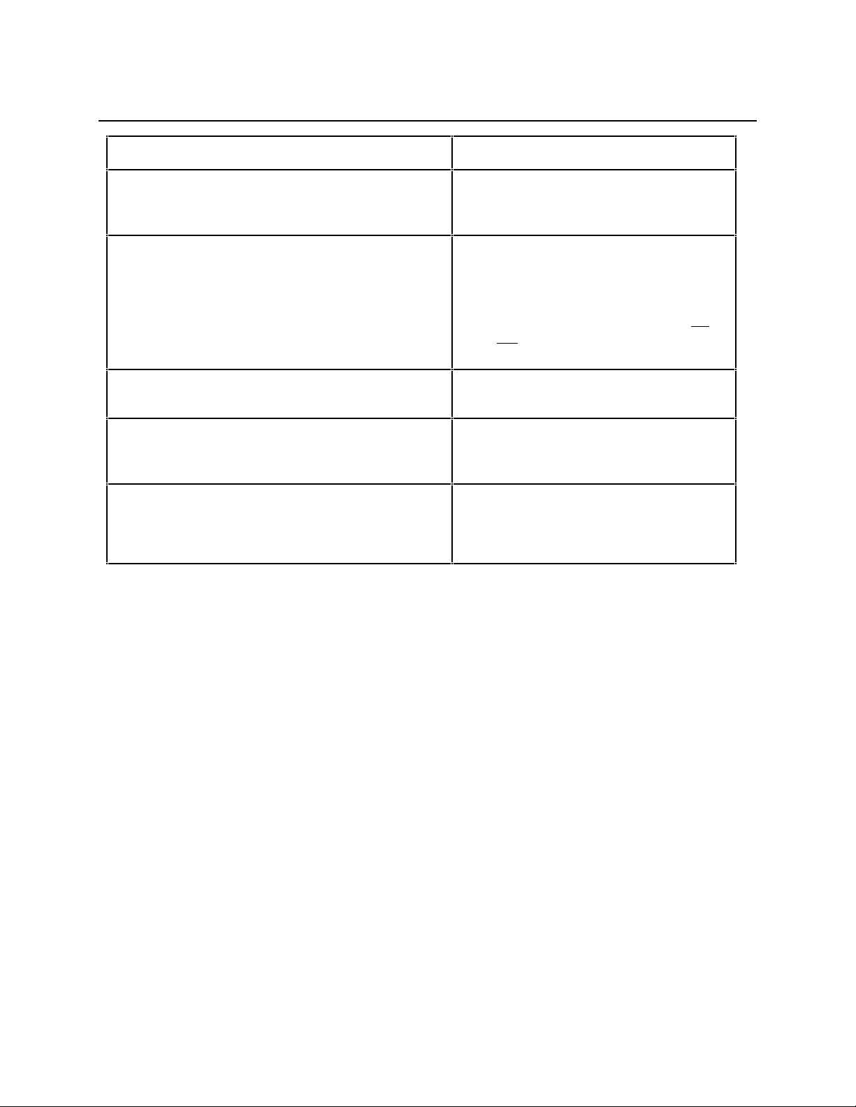
should appear as follows:
Self Test begins.
Self Test is running.
2-18 0021
Page 17
Installation Notes
Front Panel Light Activity Meaning
Ethernet A, B, or C LED ON Terminal server detects network
activity on Ethernet segment to which it
is attached..
CARD LED ON Unit is loading from a Memory card
(light ON for approximately 15 seconds).
☞ The Terminal Server 720 is
accessing the Memory card. Do
not remove the card while the
CARD light is ON.
RUN and Ethernet (A, B, or C) LEDs blink
simultaneously
Port lights go ON, sequentially from right (Port 8
status light) to left (Port 1 status light). Then,
lights go OFF from left to right.
RUN LED flashes slowly
Ethernet (A, B, or C) LED flashes when Ethernet
packets are received
If the LEDs do not behave as indicated, refer to the Appendix D.
Software load in progress.
Unit has finished loading the software
image, and is decompressing it.
Software loading has completed.
Terminal server is in normal operating
state.
0021 2-19
Page 18

Installation Notes
2.7 Initialize Connected Serial Devices
Connect a terminal to a terminal server serial port, turn its power ON, and press RETURN (or
ENTER) a few times until the terminal server recognizes your device. Note that the terminal
server serial port automatically adjusts to the communication speed of your terminal (75 bps -
38.4K bps, using 8-bit characters with no parity, or 7-bit characters with even parity; above
38.4K bps you must specify a fixed port speed). When the terminal server responds, it
generates the following message which appears on your screen:
Welcome to the Xyplex terminal server
Enter username>
Type in your name, your initials, or a nickname -- whatever you would like to be known as
while you are connected, then press RETURN again. You can type up to 16 characters
(numbers or letters). This name is your identifier during this session. If you choose, you can
change it each time you make a connection to the terminal server.
☞ Until permanent operational parameters are stored, the server will display the
following message when you log in:
Xyplex -901- Default parameters in use.
This is a normal message.
After you enter your username, the terminal server responds with the following prompt:
Xyplex>
The Terminal Server 720 is now ready to accept commands to configure the terminal server
and its ports. For example, you can obtain on-screen information about the terminal server
commands by typing HELP and pressing the RETURN or ENTER key.
☞ Some commands require a higher privilege level. Section 4.4 describes how you
become a privileged user.
2-20 0021
Page 19

Chapter 3
I/O and Cabling Considerations
3.1 Overview to Cabling
There are various serial I/O and cabling schemes available for the Terminal Server 720.
- The model 723 twenty-port I/O module. Twenty RJ-45 connectors provide connections for
twenty serial devices using modular cabling. These ports support concurrent hardware
and software flow control, at communication speeds from 75 bps to 115.2 Kbps. Section 3.2
covers cabling options for this I/O module.
- The model 721 sixteen-port I/O module. Two 50-pin TELCO connectors provide
connections for sixteen serial devices, using a variety of wiring schemes, such as
extension cables, distribution panels. splitters, octopus cables, punch-down blocks,
modular (MODtap™) cabling, and DECconnect™ cabling. These ports support modem
control (but not concurrent hardware and software flow control) at communication
speeds from 300 bps to 115.2 Kbps. Section 3.3 covers cabling options for this I/O module.
- Model 724 24-port I/O module. Three 50-pin TELCO connectors provide six-wire
connections for twenty-four serial devices, using the same wiring schemes available for
the Model 721 I/O module. These ports support modem control signals and communication
speeds from 75 bps to 115.2 Kbps. Section 3.3 covers cabling options for this I/O module.
☞ When using port speeds higher than 64 kbps, you must be careful to use a cabling scheme
that minimizes the potential for "cross-talk" problems. Cabling methods, such as punchdown blocks used in conjunction with bundled 50-wire cables can suffer from cross-talk at
these data rates. It is recommended that you use separate shielded cables for each port (for
example, an octopus cable), when using the TELCO I/O modules, or short cable lengths.
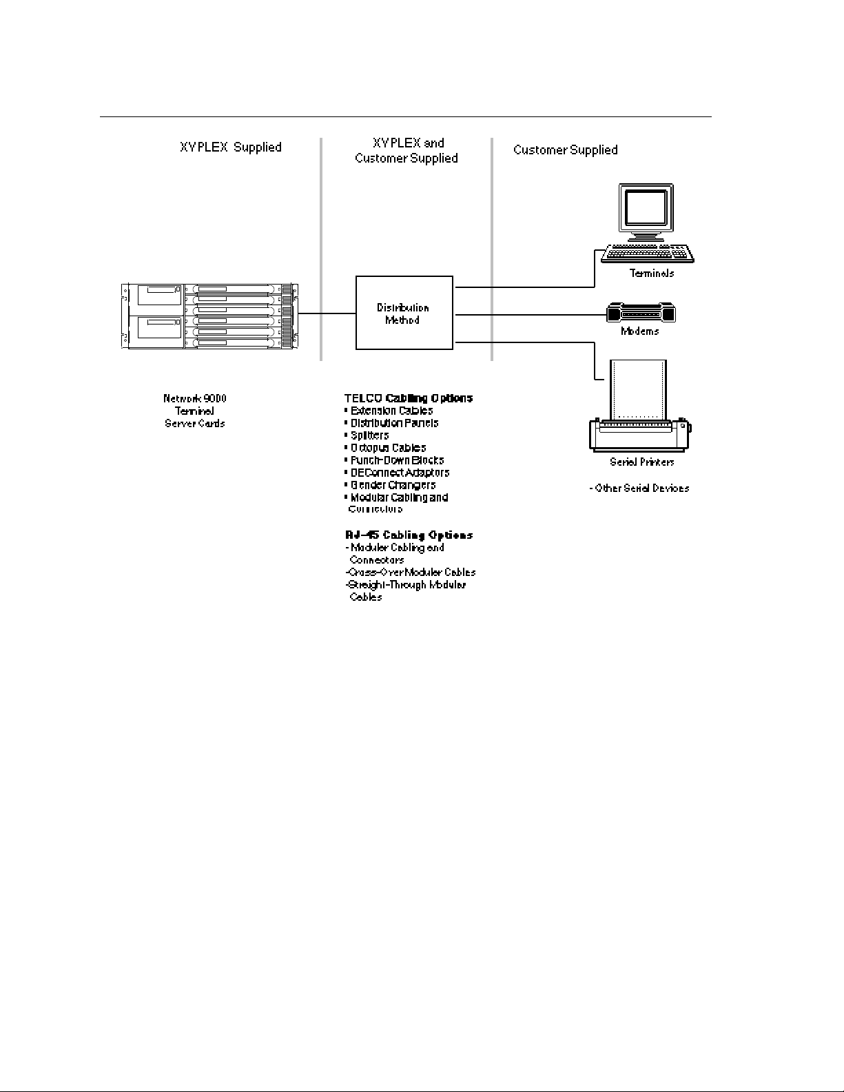
This chapter describes the cabling and signal distribution considerations for Terminal
Server 720. Some of the cabling and distribution items are available from Xyplex. Other
cabling items are supplied by the customer. Depending on your application, there are different
cabling schemes that you can use. Figure 3-1 provides an overview of the cabling and
distribution options available to you.
Serial connections are made at connectors on the I/O module. A signal listing is included for
each cabling option so you will be able to understand how to wire/connect to devices.
For each cabling option, pinouts are included so you will be able to wire/connect to serial
devices. Refer also to the Customer Device Wiring Considerations description in Section 3.3.2
(RJ-45) or 3.3.12 (Telco) for information regarding DTE-to-DTE and DTE-to-DCE (crossover
and straight through) connections.
0021 3-21
Page 20
I/O and Cabling Considerations
Figure 3-1. Cabling Overview.
The following signal abbreviations will be used throughout this chapter:
Abbreviation Signal Name Type Available For:
DTR Data Terminal Ready Output RJ45, Telco
XMT Transmit Data Output RJ45, Telco
RTS Request to Send Output RJ45
GND Ground - RJ45, Telco
RCV Receive Data Input RJ45, Telco
DCD Data Carrier Detect Input RJ45, Telco
RNG Ring Indicator Input RJ45, Telco
CTS Clear to Send Input RJ45
DSR Data Set Ready Input RJ45
3-22 0021
Page 21

I/O and Cabling Considerations
3.2 RJ-45 Cabling Options
The 20-port I/O modules use modular cables that are designed for easy cable connections. The
cabling options available from Xyplex include (Chapter 6 lists the order codes for these items):
• Crossover cables (male RJ-45 to male RJ-45, 10 and 25 feet)
• Straight-through cables (male RJ-45 to male RJ-45; lengths: 1, 10, and 25 feet)
• "Octopus" cables (a single 50-pin male or female Telco connector, or a 36-pin male or female
Telco DECconnect connector, fanning out to eight male RJ-45 connectors)
• DECconnect crossover cable (male RJ-45 to male MMJ, 10 and 25 feet)
• Modular adaptors:
- Female RJ-45 to male DB-25, supporting RING signal
- Female RJ-45 to male DB-25, supporting RTS/CTS flow control (Modems that
perform compression/decompression typically use this type of flow control.)
- Female RJ-45 to female DB-25
- Female RJ-45 to female MMJ
- Female RJ-45 to female RJ-45
- Male RJ-45 to female RJ-12
- Male RJ-45 to female MMJ
• Customer cable-making kits
Standard cabling items available from Xyplex allow you to connect to any serial device that
uses a male or female DB-25 connector. All you need is the appropriate modular cable
(crossover cable for connecting to a DTE device, straight-through cable for connecting to a DCE
device), and the correct modular adaptor (male or female DB-25 connector), which is
essentially an RJ-45-to-DB25 adaptor.
Xyplex also supplies DECconnect-compatible crossover cables and modular adaptors for use
with the 20-port I/O modules. These cables are described later in Section 3.2.4
3.2.1 Making Your Own RJ-45 Cables
If you make your own cables, you should be very careful when using the crimping tool. Make
sure that the RJ-45 connector is fully inserted into the die set cavity of the crimping tool, and that
the wire is fully inserted into the RJ-45 connector, before crimping. The die set might be fragile,
and could break if the RJ-45 connector is not properly seated before you squeeze the handle.
Also, Xyplex recommends that you use different colored wires for straight-through and
crossover cables, in order to keep track of the cable type.
0021 3-23
Page 22
I/O and Cabling Considerations
3.2.2 Device Wiring Considerations (RJ-45)
Using the model 723 I/O module, you will normally connect the serial device cables to the 8-pin
RJ-45 jacks on the I/O module. It does not matter which port you connect a device to; the I/O
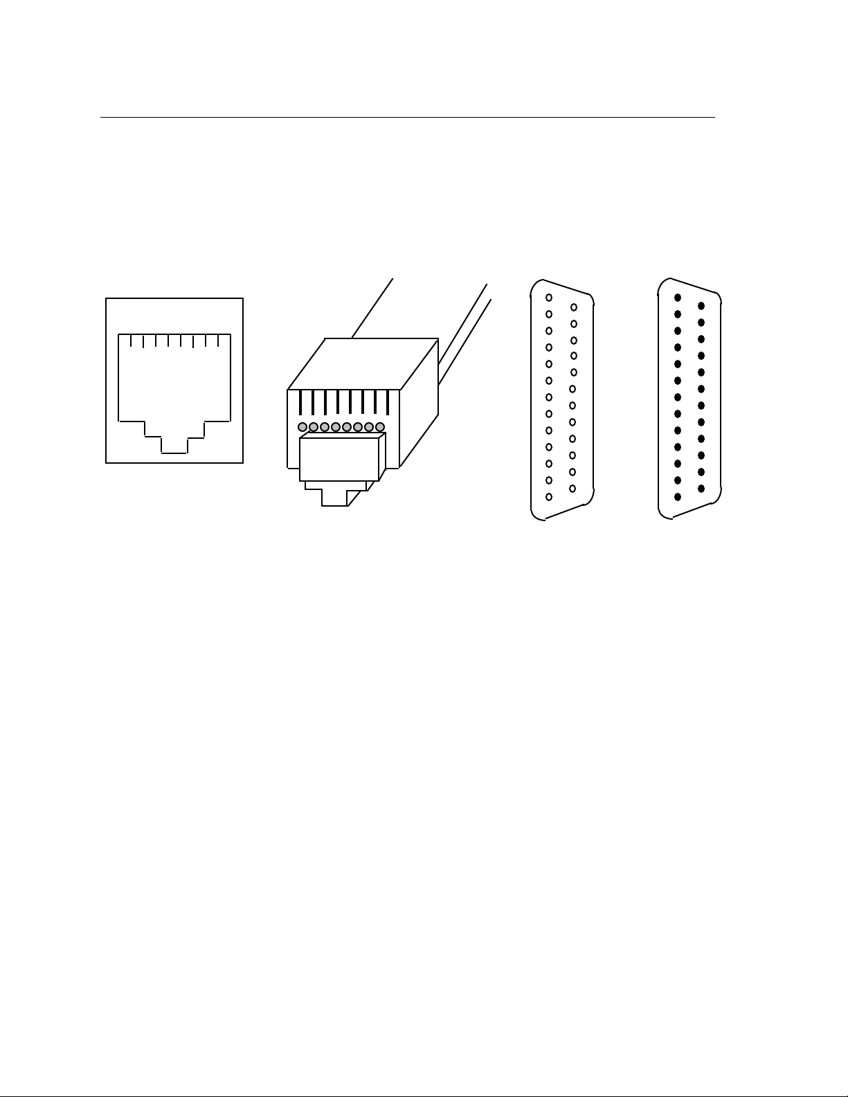
module provides full support to each port. The female RJ-45 jack shown in Figure 3-2 shows the
signal assignments of the 8-pin jacks.
1 2 3 4 5 6 7 8
RJ-45 Jack
(Female)
Female RJ-45 Pin Signal
1 RNG/CTS (input)
2 DTR (output)
3 XMT (output)
4 XMTGND
5 RCVGND
6 RCV (input)
7 DSR/DCD (input; see note after Figure 3-3)
8 RTS (output)
8 7 6 5 4 3 2 1
RJ-45 Plug
(Male)
Figure 3-2. RJ-45, DB-25 Pins
1
14
25
13
DB-25
(Female)
13
1
DB-25
(Male)
25
14
You should also give special consideration to the wiring scheme when connecting a device
such as a terminal to a serial port. Using modular cabling options (see section 3.2.3), signals
are directed to the correct pins by the adaptor. If you wish to make your own cables, you must
construct the cable with the appropriate wiring scheme. The terminal server is considered a
DTE device.
3-24 0021
Page 23

I/O and Cabling Considerations
If you want to connect to another DTE device, you will need a crossover wiring scheme
somewhere in the cabling. (Communication between DTE-to-DTE devices requires a
crossover.) To make a modular cable with a crossover, you need only crimp the RJ-45
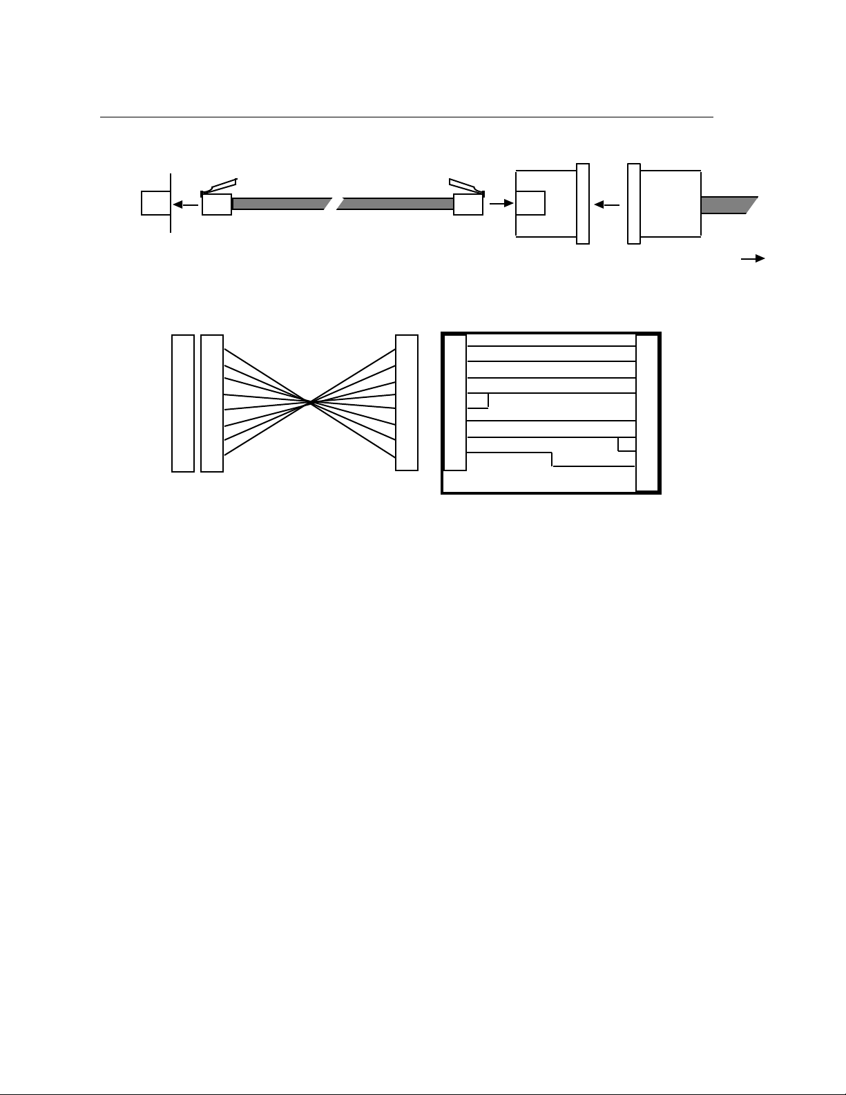
connector in the same direction at both ends. This crosses all wires in the cable. Figure 3-3
shows the crossover wiring scheme. Typically, to connect a standard terminal to a serial port
you would use a crossover cable with female DB-25 adaptor at the terminal end.
The crossover connects the terminal server transmit data (XMT) line to the receive data (RCV)
line of the user DTE device. Similarly, the terminal server receive data (RCV) line crosses
over to the transmit data (XMT) line of the user DTE device. The other signals are crossed
over in a similar manner (see Figure 3-3).
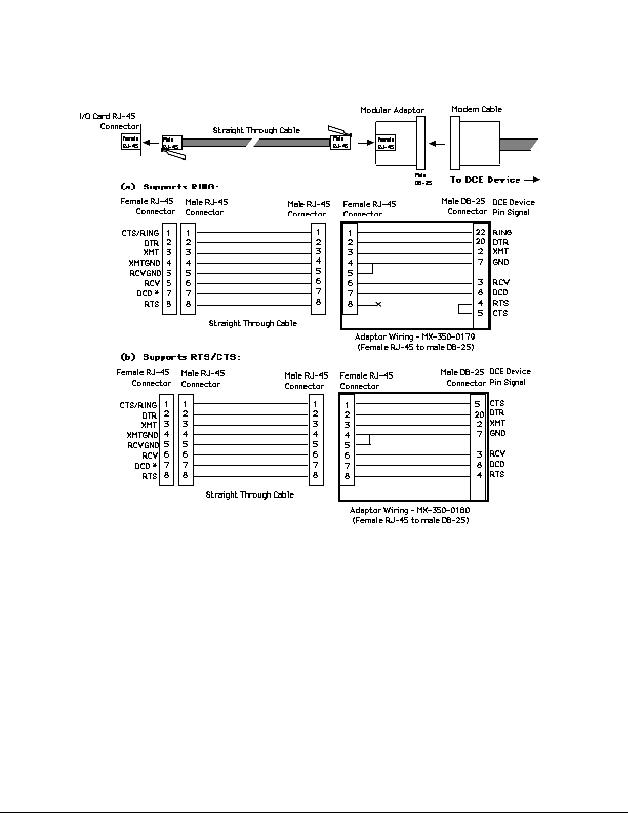
If you want to connect a DCE device to a terminal server serial port, straight-through wiring is
required. To make a modular straight-through cable, you need only crimp the RJ-45 connector
in opposite directions at both ends. Figure 3-4 shows the straight-through wiring scheme.
3.2.3 Modular Adaptors (RJ-45 to DB-25)
You can obtain adaptors with male and female DB-25 connectors from Xyplex. These adaptors
direct signals from the RJ-45 connector on the cable to the correct pin on the DB-25 connector.
Figures 3-3 and 3-4 show how devices are cabled when you use these adaptors.
Flow Control and Modem Control
The model 721 20-port I/O module's serial ports can be set up to support RTS/CTS flow control,
modem control, or both of these concurrently. Section 5.6 of the Software Management Guide
describes flow control options and explains how to set up flow control at a port. The adaptors
shown in Figures 3-3 and 3-4(b) support RTS/CTS flow control. Terminal Server 720 RJ-45
serial ports can also be set up to support modem control. Section 5.5 of the Software
Management Guide describes modem control options and explains how to set up modem
control at a port. The adaptor shown in Figure 3-4(a) supports modem control, by supporting the
RING signal.
0021 3-25
Page 24
I/O and Cabling Considerations
(Female RJ-45 to female DB-25)
Connector
Female
RJ-45
Female
RJ-45
Female
DB-25
Modular Adaptor
To DTE Device
DTE Cable
Male
RJ-45
Male
RJ-45
I/O Card RJ-45
Connector
Crossover Cable
Female RJ-45
CTS/RING
DTR
XMT
XMTGND
RCVGND
RCV
DSR *
RTS
1
2
3
4
5
6
7
8
Male RJ-45
Connector
1
2
3
4
5
6
7
8
Male RJ-45
Connector
1
2
3
4
5
6
7
8
Female RJ-45
Connector
1
2
3
4
5
6
7
8
Female DB-25
Connector
5
20
2
7
3
8
6
4
Crossover Cable
Adaptor Wiring - MX-350-0181
* (See Note, after Figure)
Figure 3-3. Terminal Server to DTE Adaptor Wiring
Note In order to expand the functionality of the serial interface, the RJ-45 modular
cabling allows you to connect different signals to pin 7 of the server. (This pin is
an input to the terminal server serial port.) When a DCE device is connected to a
terminal server serial port, the device's DCD output is connected to pin 7. In this
case, the signal at pin 7 is referred to as DCD.
When a DTE device is connected to a terminal server serial port, the device's
DTR output is connected to pin 7 of the terminal server. In this case, the signal at
pin 7 is referred to as DSR. (This cabling scheme also provides DECconnect
compatibility, since DECconnect does not support the DCD signal.)
DTE Device
Pin Signal
CTS
DTR
XMT
GND
RCV
DCD
DSR
RTS
3-26 0021
Page 25
I/O and Cabling Considerations
* (See Note, before Figure 3-4)
Figure 3-4. Adaptor Wiring, Server to DCE
0021 3-27
Page 26
I/O and Cabling Considerations
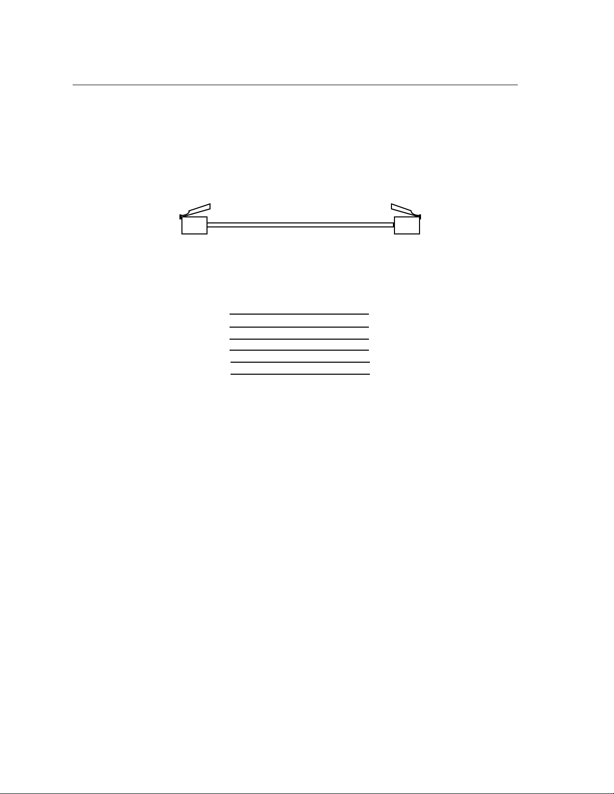
3.2.4 DECconnect RJ-45 Cables
Figure 3-5 shows the DECconnect-compatible cables available from Xyplex and shows how the
cables are wired. The Male RJ-45 connector is attached to the server. The MMJ connector
attaches to the DECconnect-compatible device (DTE). The cable is a crossover cable that uses
the six inner pins of the server port and makes the signals available at the MMJ connector.
The cable is constructed using standard six-wire cable.
DEConnect Crossover Cable
Male RJ-45
Connector
Male MMJ
Connectors
1 RING/CTS
2 DTR
3 XMT
4 XMTGND
5 RCVGND
6 RCV
7 DSR/DCD
6 DSR
5 RCV
4 RCVGND
3 XMTGND
2 XMT
1 DTR
8 RTS
Figure 3-5. RJ-45 DECconnect Cable
If you have existing DECconnect cables that you want to use with the RJ-45 serial ports, the onefoot straight through cable and the RJ-45 to MMJ adaptor or modular adaptor allow you to use
these cables without making any changes. You can also use the male RJ-45 to female MMJ
adaptor. You should also note that DECconnect cables do not support hardware flow control.
3-28 0021
Page 27
I/O and Cabling Considerations
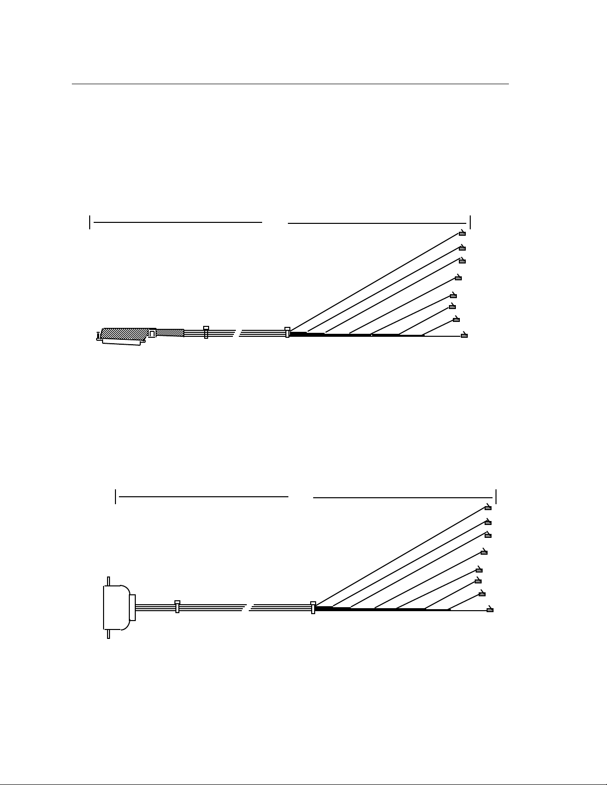
3.2.5 Octopus Cables
An octopus cable fans out a single 50-pin male or female Telco connector, or a 36-pin male or
female Telco DECconnect connector, to eight male RJ-45 connectors. These cables enable you
to connect RJ-45 serial ports to existing wiring in your facility. For example, you can use
octopus cables to connect the RJ-45 serial ports to a punch down block.
Figure 3-6 shows an octopus cable with a 50-pin Telco connector:
6'
50-pin Telco connector
(male or female)
Eight male RJ-45
connectors
Figure 3-6. Octopus Cable with 50-pin Telco Connector
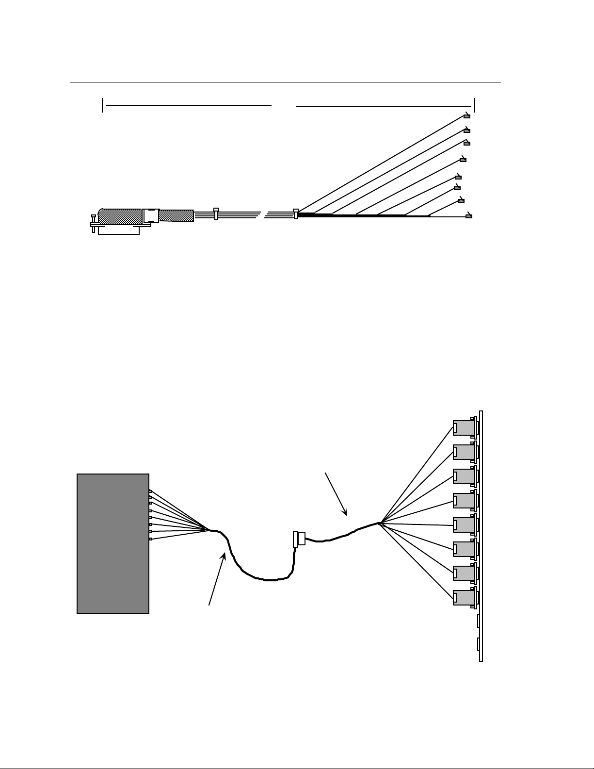
Figures 3-7 shows an octopus cable with a 36-pin female Telco DECconnect connector. Figure
3-8 shows an octopus cable with a 36-pin male Telco DECconnect connector.
6'
36-pin female Telco
DEConnect connector
Eight male RJ-45
connectors
Figure 3-7. Octopus Cable With 36-pin Female DECconnect Connector
0021 3-29
Page 28
I/O and Cabling Considerations
Octopus cable: 8 RJ-45
to 50-pin female Telco
Octopus cable: 8 DB-25
(male or female) to 50-pin
male Telco
6'
Eight male RJ-45
36-pin male Telco
DEConnect connector
connectors
Figure 3-8. Octopus Cable With 36-pin Male DECconnect connector
Connecting to a Distribution Panel
By using two types of octopus cable, you can connect RJ-45 serial ports to a distribution panel
that has DB-25 connectors. This enables you to adapt RJ-45 cabling to Xyplex Telco-style
cabling. Xyplex offers octopus cables that fan out a 50-pin Telco connector to eight male or
female DB-25 connectors. These cables are available in 3', 6', 10', 25' and 50' lengths. You
can connect the unit to the distribution panel via the two octopus cables as shown in Figure 3-9.
(You might need an extension cable to connect the two cables.)
Terminal Server
720 I/O Module
Figure 3-9. Connecting RJ-45 Ports to a DB-25 Distribution Panel
3-30 0021
Distribution panel
Page 29
I/O and Cabling Considerations
3.3 Telco Cabling Options
The model 721 16-port I/O module and model 724 24-port I/O module can be used with a variety
of cabling options that are designed for easy cable connections. The cabling options available
from Xyplex include:
• Extension cables
• Distribution panels
• Splitters
• Octopus cables
• Punch-down blocks
• Modular (MODtap™) cabling
• DECconnect™ cabling
Standard cabling items available from Xyplex allow you to connect to any serial device that
uses a male or female DB-25 connector.
Xyplex also supplies DECconnect-compatible crossover cables and modular adaptors for use
with the 20-port I/O modules. These cables are described later in this chapter.
3.3.1 Rear Panel Connection (Telco)
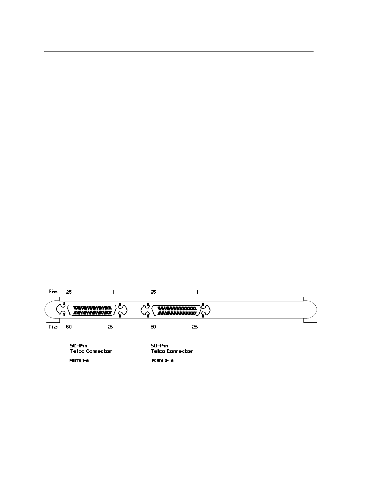
The Model 721 I/O module has two 50-pin female Telco/Amphenol connectors with bail locks,
as shown in Figure 3-10. The Model 724 I/O module is similar to the Model 721, but has has
three 50-pin female Telco/Amphenol connectors with bail locks. The bail locks swing in
toward the male connector and latch to secure the connection. Standard Xyplex cables use
connectors with the bail locks.
Figure 3-10. Sixteen-Port I/O Module, With 50-Pin Telco Connectors.
Table 3-1 lists the Telco 50-pin connector pin assignments for the Terminal Server 720
sixteen-port I/O module. Typically, an extension cable, with either a straight-out or bottomentry male connector is mated to the Telco connector (section 3.3.2).
☞ The model 721 and 724 I/O modules do not support hardware flow control.
0021 3-31
Page 30

I/O and Cabling Considerations
Table 3-1. Telco 50-Pin Pinout, By Port Number
Telco Signal Telco Signal
Pin Name Pin Name
Port 1, 9, 17 28 DTRn 03 RNGn
27 XMTn 02 GNDn
26 RCVn 01 DCDn
Port 2, 10, 18 31 DTRn 06 RNGn
30 XMTn 05 GNDn
29 RCVn 04 DCDn
Port 3, 11, 19 34 DTRn 09 RNGn
33 XMTn 08 GNDn
32 RCVn 07 DCDn
Port 4, 12, 20 37 DTRn 12 RNGn
36 XMTn 11 GNDn
35 RCVn 10 DCDn
Port 5, 13, 21 40 DTRn 15 RNGn
39 XMTn 14 GNDn
38 RCVn 13 DCDn
Port 6, 14, 22 43 DTRn 18 RNGn
42 XMTn 17 GNDn
41 RCVn 16 DCDn
Port 7, 15, 23 46 DTRn 21 RNGn
45 XMTn 20 GNDn
44 RCVn 19 DCDn
Port 8, 16, 24 49 DTRn 24 RNGn
48 XMTn 23 GNDn
47 RCVn 22 DCDn
Note 1: Ports 1 through 8 are on connector A. Ports 9 through 16 are on connector B.
Ports 17 through 24 on connector C.
Note 2: Pins 25 and 50 are not used.
Note 3: The signal definitions are:
Signal Definition Type
DTRn Data Terminal Ready Output (From server to terminal)
XMTn Transmit Output (From server to terminal)
DCDn Data Carrier Detect Input (From terminal to server)
RCVn Receive Input (From terminal to server)
GNDn Logic Ground Common
RNGn Ring Input (From terminal to server)
where: n is the port number.
3-32 0021
Page 31
I/O and Cabling Considerations
TELCO (50-Pin)
Male Connector
TELCO (50-Pin)
Male Connector
TELCO (50-Pin)
Female Connector
Bottom-Entry
50-Pin Male or
Female Connector
STANDARD
OPTIONAL
111
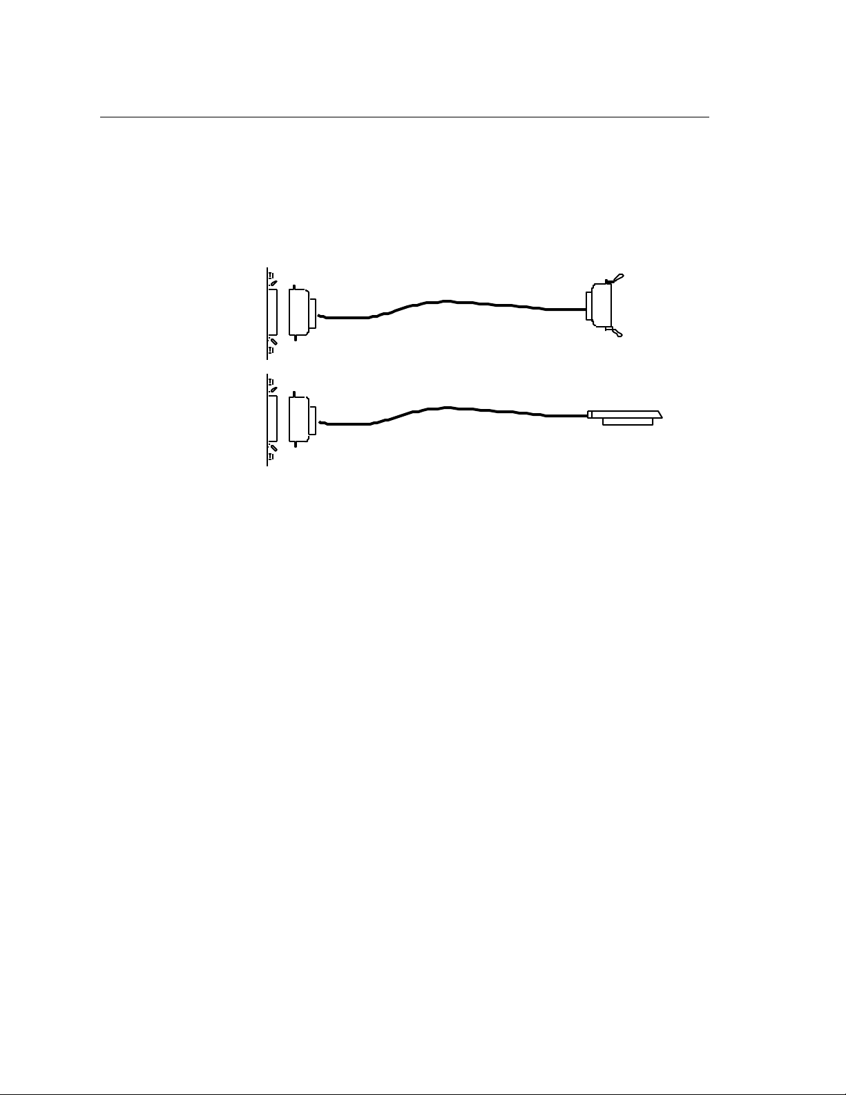
3.3.2 Extension Cables
Two basic types of extension cables of various lengths are available as shown in Figure 3-11.
Both types have 50-pin Telco (male) connectors at one end and either a 50-pin Telco (female)
connector, or a 50-pin bottom-entry connector (male or female) at the other end. (Refer to
paragraph 3.3.10 for a DECconnect-style extension cable.)
I/O Card
Figure 3-11. Extension Cables.
The available lengths for each type are:
Telco Male to Telco Female Telco Male to Bottom-Entry Female/Male
0.91 m (3') 3.05 m (10') to bottom-entry female
3.05 m (10') 7.62 m (25') to bottom-entry female
7.62 m (25') 7.62 m (25') to bottom-entry male
15.24 m (50')
Either the Telco male to Telco female or the Telco male to bottom-entry male can connect
directly to the I/O module. These extensions cables provide a straight through connection so
combinations of various male-to-female cable lengths can be connected together to give you the
length you require.
These extension cables can be used to or from the I/O module to the following cabling options:
• Octopus Cables
• Distribution Panel
• Modular Splitter
• Punch-Down Block
• Extend existing cable
0021 3-33
Page 32
I/O and Cabling Considerations
Terminal Server
720 I/O Module
Octopus cable: 8 DB-25
(male or female) to 50-pin
male Telco
22 RNG
20 DTR
DCD 8
GND 7
RCV 3
XMT 2
MALE PINOUTS
RCV 2
XMT 3
GND 7
DTR 8
20 DCD
22 RNG
FEMALE PINOUTS
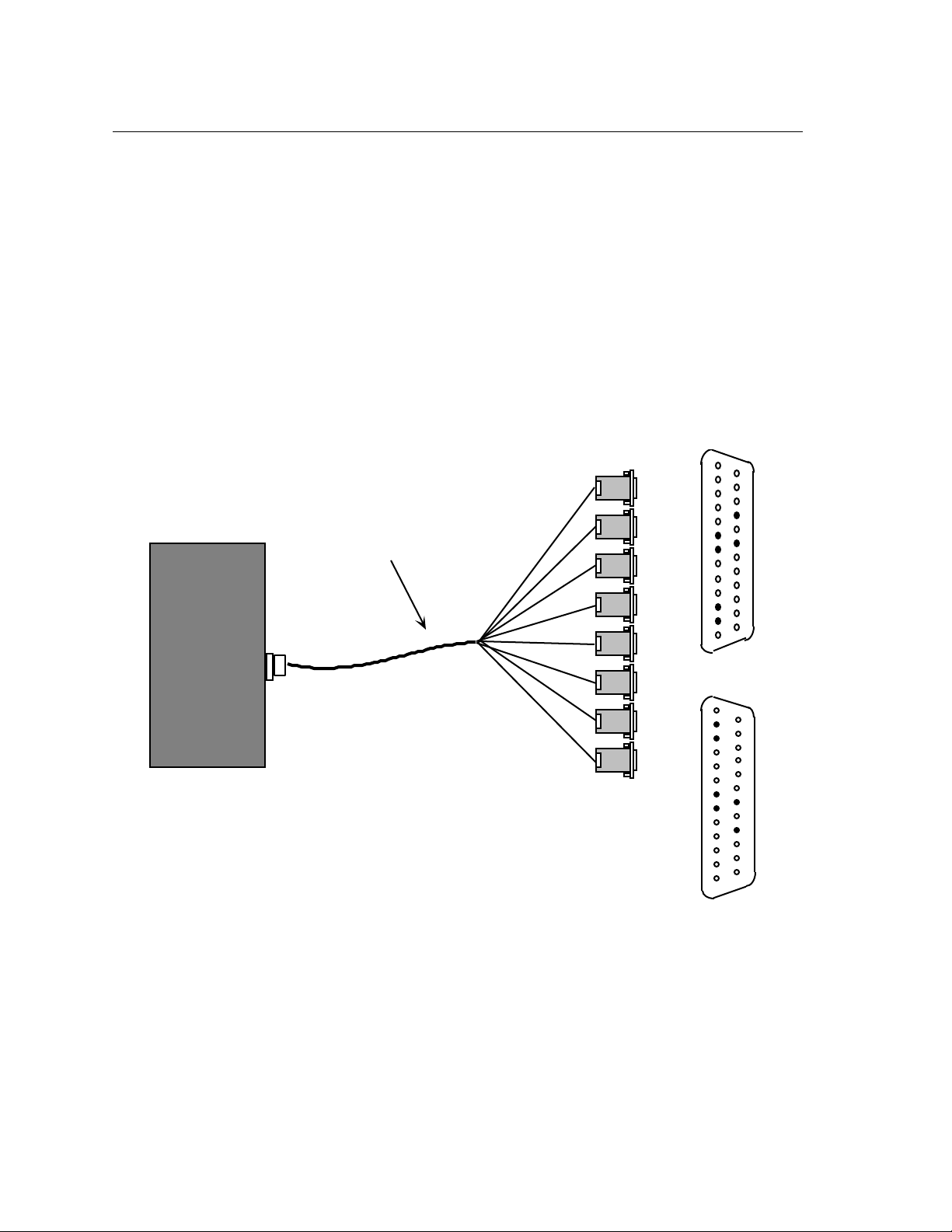
3.3.3 Octopus Cables
An octopus cable fans out the 8 serial ports from a 50-pin Telco connector to DB25 connectors
(6-pins used per connector). An octopus cable can be ordered with either 8 male or female
DB25 connectors as shown in Figure 3-12. The following cable lengths are available for both
octopus cable types:
• 0.91 m (3 ft)
• 1.83 m (6 ft)
• 7.62 m (25 ft)
• 15.24 m (50 ft)
3-34 0021
Figure 3-12. Octopus Cable (Male and Female), Connected to I/O Module.
Page 33
I/O and Cabling Considerations
Extension cable: 50-pin male
Telco to 50-pin female Telco
Octopus cable: 8 DB-25
(male or female) to 50-pin
male Telco
Terminal Server
720 I/O Module
Modem (DCE)
Terminal (DTE)
Crossover cable needed
Straight through cable needed
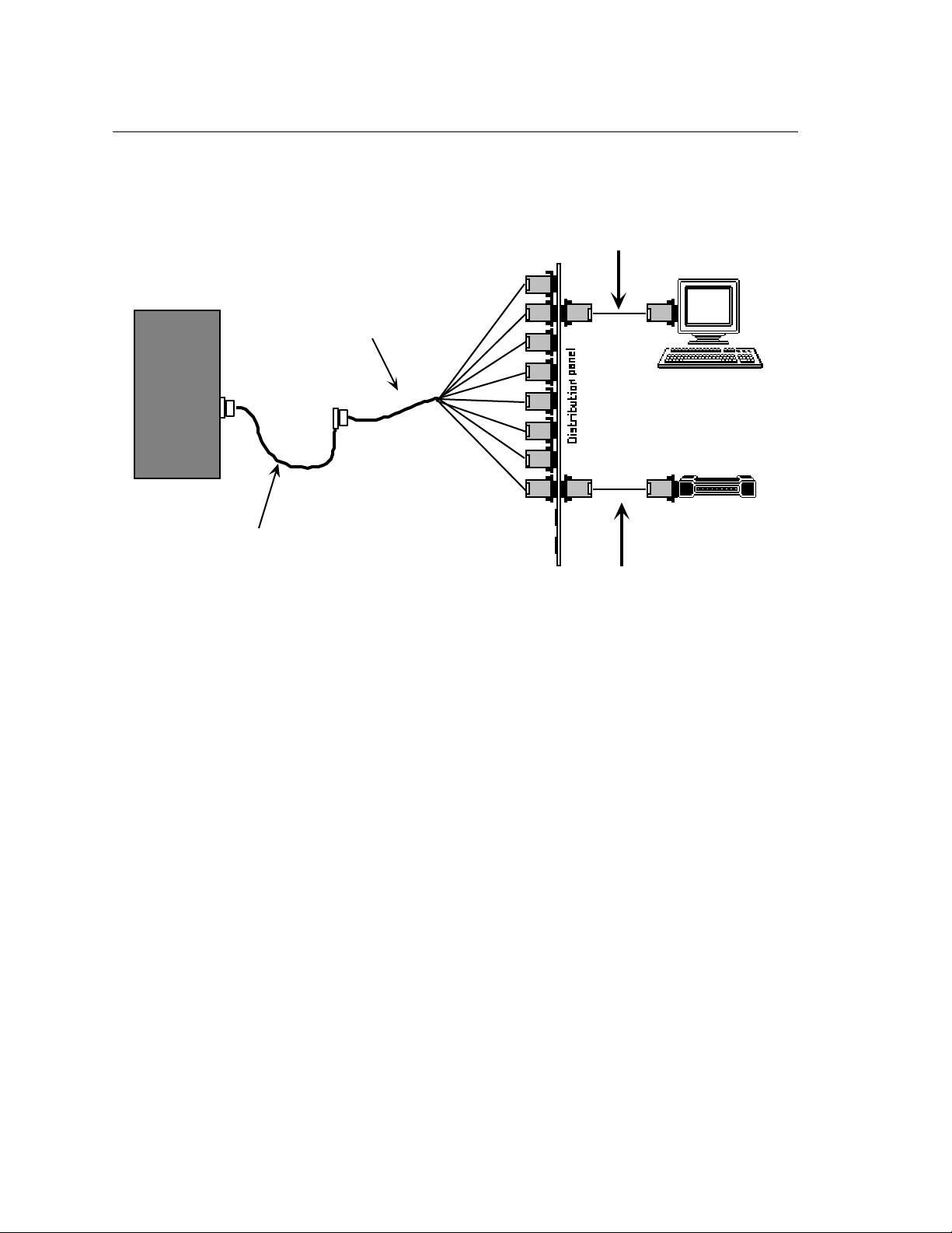
Figure 3-13 shows possible terminal server (DTE) connections to a terminal (DTE) and a
modem (DCE) using an Octopus cable with male DB-25 connectors installed in a distribution
panel (section 3.3.4).
Figure 3-13. Terminal Server (DTE) To DTE/DCE Applications.
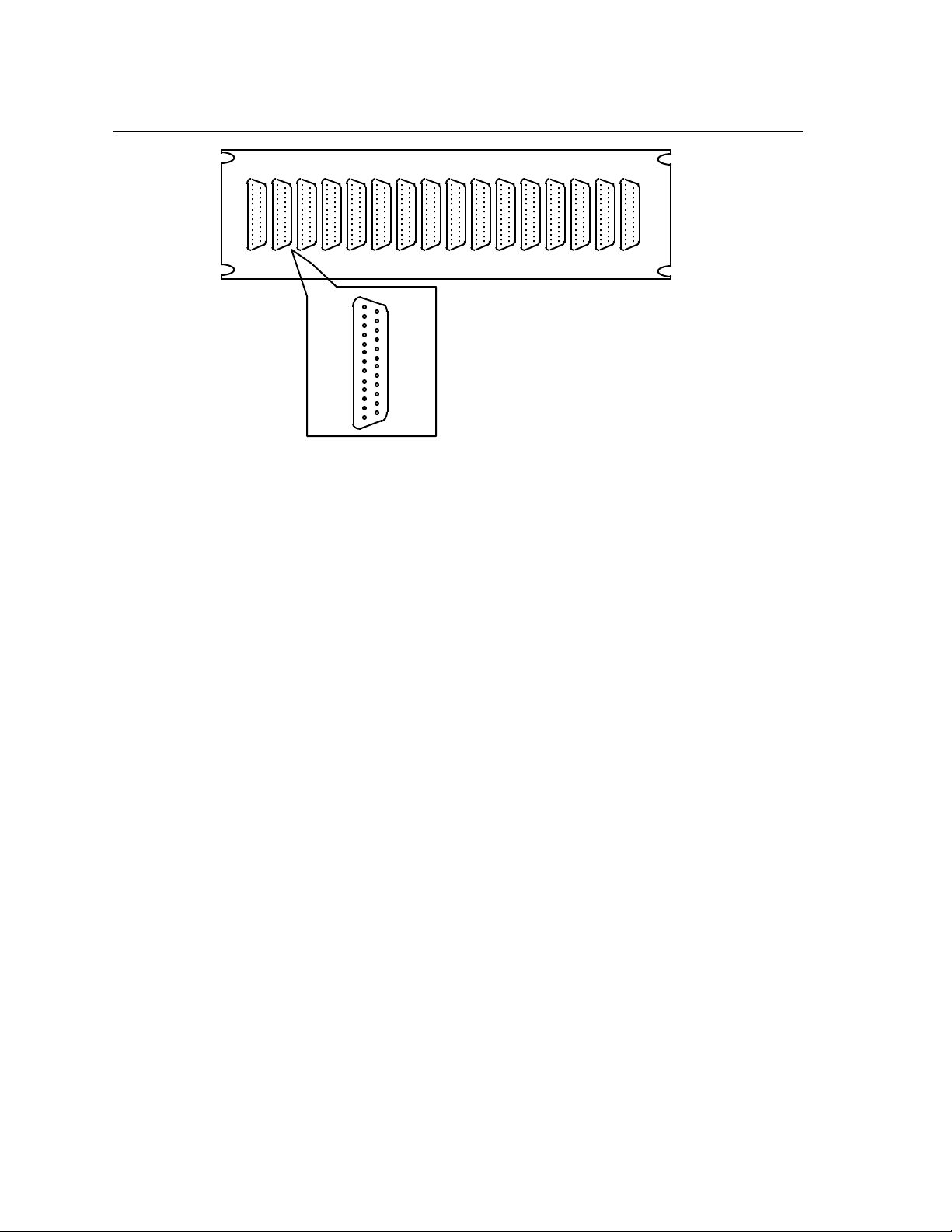
3.3.4 Distribution Panels (16-Port, DB-25)
A 16-port distribution panel with two 1.83 m (6 ft) Octopus cables (Male DB-25 connectors)
installed is available (Figure 3-14). Alternately, a blank distribution panel and hardware kit
(not shown) can be ordered that accepts 2 Octopus cables with male or female connectors. These
distribution panels are most commonly used as a distribution point for terminal connections.
0021 3-35
Page 34
I/O and Cabling Considerations
1 2 3 4 5 6 7 8 1 2 3 4 5 6 7 8
XYPLEX
105
Shown as
Male to DCE
DCD 8
GND 7
RCV 3
XMT 2
22 RNG
20 DTR
Figure 3-14. 16-Port Distribution Panel.
3-36 0021
Page 35
I/O and Cabling Considerations
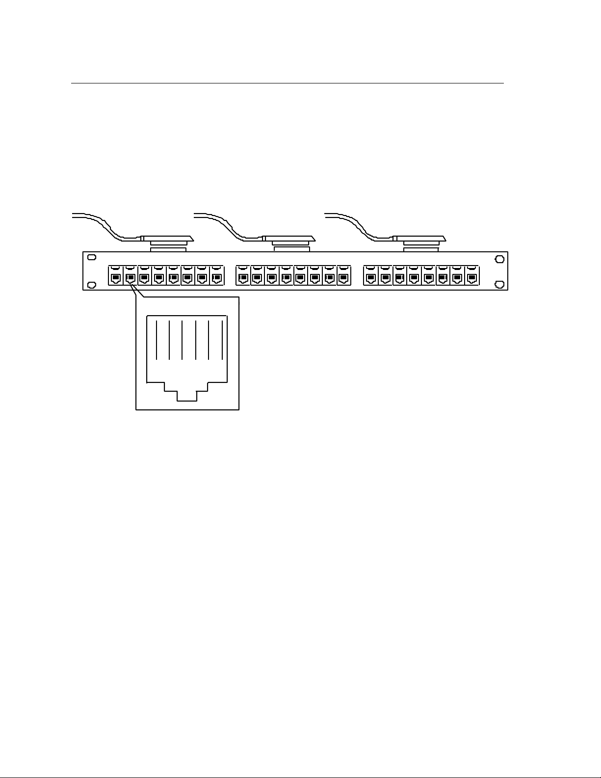
3.3.5 Modular Splitters
A modular splitter is a rack-mount distribution panel that fans out to eight 6-pin ports through
RJ-12 jacks as shown in Figure 3-15. The splitter has 3 groups of 8 ports as shown and requires
three 50-pin extension cables. A modular splitter works best with a 50-pin female bottom-entry
extension cable. A single 8-port splitter requiring one 50-pin input is also available.
Modular splitter applications include: office drops, MOD-TAP™ and DECconnect™ wiring.
24 PORT
MODULAR
SPLITTER
2 3 5 6 748
1
1 2 3 5 6 74 8
1 2 3 5 6 74 8
1 2 3 4 5 6
102.0
DTR DCD
XMT
RCV
GND
RNG
Figure 3-15. 24-Port Modular Splitter
3.3.6 Modular Cables and Connectors
Xyplex can supply the following modular items for wiring from a splitter to your devices:
• 6-wire cable 7.62 m (25')
• SYS Connector, Blue and Grey (MOD-TAP #060988-523-30)
XYPLEX
• DROP Connector, White and Grey (MOD-TAP #06-988-260-20)
Other cabling options (not available from Xyplex) include:
• SYS Adaptor, female RJ-12 to male DB-25, Blue and Grey (MOD-TAP #06-888-523-30)
• DROP Adaptor, female RJ-12 to male DB-25, White and Grey (MOD-TAP #06-888-260-20)
Standard Xyplex-supplied cabling items allow you to connect to any serial device which uses a
male or female DB-25 connector. All that is required is the modular cable, and the correct
modular adaptor (male or female DB-25 connector), which is essentially an RJ-12-to-DB25
0021 3-37
Page 36
I/O and Cabling Considerations
adaptor. The DROP adaptors are used in server-to-DTE connections (cross over is performed
by the adaptor). The SYS adaptors are used for server-to-DCE connections.
3.3.7 Punch Down Block (66M Style)
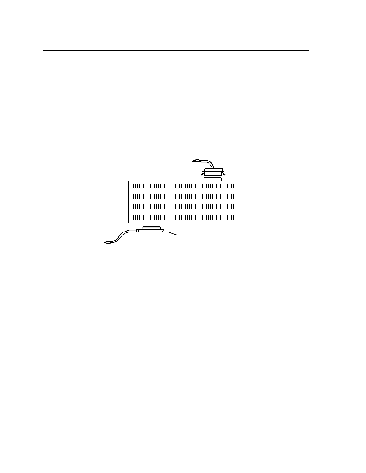
The 66M style punch-down block is a 50-pins by 4 rows distribution terminal block used in
wiring closets and telephone wiring applications. A 50-pin Telco/Amphenol male connector is
mounted on each side of the block as shown in Figure 3-16. Xyplex recommends that bottomentry extension cables be used with velcro fasteners. (There are no bail-lock latches on the
block for the other type of connector.) Two 50-pin rows are associated with each pin. One row
connects to the input connector and the other row accepts the wiring to the telephone wiring, with
6 pins per port. Table 3-2 describes the connections for Xyplex supplied 66M punch-down blocks.
(For the Model 724 24-port Telco I/O module, you need to use two 50-pin punch-down blocks.)
USE BOTTOM ENTRY
EXTENSION CABLES
WITH VELCRO FASTENERS
FOR SECURE CONNECTIONS
Figure 3-16. 66M Punch Down Block.
114.2
3-38 0021
Page 37

I/O and Cabling Considerations
Table 3-2. Pinouts for 66M Punch Down Block.
Connection Number (Row) TELCO Connector 1 TELCO Connector 2 Signal
1 26 26 RCV1 or RCV9
2 1 1 DCD1 or DCD9
3 27 27 XMT1 or XMT9
4 2 2 GND1 or GND9
5 28 28 DTR1 or DTR9
6 3 3 RNG1 or RNG9
7 29 29 RCV2 or RCV10
8 4 4 DCD2 or DCD10
9 30 30 XMT2 or XMT10
10 5 5 GND2 or GND10
11 31 31 DTR2 or DTR10
12 6 6 RNG2 or RNG10
13 32 32 RCV3 or RCV11
14 7 7 DCD3 or DCD11
15 33 33 XMT3 or XMT11
16 8 8 GND3 or GND11
17 34 34 DTR3 or DTR11
18 9 9 RNG3 or RNG11
19 35 35 RCV4 or RCV12
20 10 10 DCD4 or DCD12
21 36 36 XMT4 or XMT12
22 11 11 GND4 or GND12
23 37 37 DTR4 or DTR12
24 12 12 RNG4 or RNG12
25 38 38 RCV5 or RCV13
26 13 13 DCD5 or DCD13
27 39 39 XMT5 or XMT13
28 14 14 GND5 or GND13
29 40 40 DTR5 or DTR13
30 15 15 RNG5 or RNG13
31 41 41 RCV6 or RCV14
32 16 16 DCD6 or DCD14
33 42 42 XMT6 or XMT14
34 17 17 GND6 or GND14
35 43 43 DTR6 or DTR14
36 18 18 RNG6 or RNG14
37 44 44 RCV7 or RCV15
38 19 19 DCD7 or DCD15
39 45 45 XMT7 or XMT15
40 20 20 GND7 or GND15
41 46 46 DTR7 or DTR15
42 21 21 RNG7 or RNG15
43 47 47 RCV8 or RCV16
44 22 22 DCD8 or DCD16
45 48 48 XMT8 or XMT16
46 23 23 GND8 or GND16
47 49 49 DTR8 or DTR16
48 24 24 RNG8 or RNG16
49 50 50 not used
50 25 25 not used
0021 3-39
Page 38

I/O and Cabling Considerations
3.3.8 Gender Changer (Telco 50-Pin, Male-To-Male)
A Gender Changer is a connector adaptor that can be used in any application requiring the
opposite connector gender between 2 existing cables, or a cable and a device such as a modular
splitter or customer-supplied punch-down block.
3.3.9 DECconnect™ 36-Pin Serial Interface Connections
The Xyplex 50-pin terminal server interface is easily integrated into the DEC RS-423 36-pin
environment. The conversion to 36-pins occurs in the cabling to the serial devices by using a
50-pin Telco to 36-pin Telco DECconnect adaptor cable.
3.3.10 DECconnect Adaptor Cables
Conversion from the 50-pin (6 pins per port) interface to the DECconnect 36-pin DEC RS-423
interface is accomplished in the cabling with a Xyplex 50-pin Telco (Male) to 36-pin Telco (Male
or Female) cable (Figure 3-17). Note that there are 4 pins per port at the 36-pin end (Table 3-3).
TELCO (50-PIN)
MALE
TELCO (36-PIN)
FEMALE
120.1
Figure 3-17. Telco 50-Pin (Male) To Telco 36-Pin (Female) Cable.
3-40 0021
Page 39

I/O and Cabling Considerations
Table 3-3. Telco 36-Pin Pinout
Telco Signal Telco Signal
Pin Name Pin Name
Port 1 or 9: 1 XMTn 19 XMTn GND
2 RCVn 20 RCVn GND
Port 2 or 10: 3 XMTn 21 XMTn GND
4 RCVn 22 RCVn GND
Port 3 or 11 5 XMTn 23 XMTn GND
6 RCVn 24 RCVn GND
Port 4 or 12: 7 XMTn 25 XMTn GND
8 RCVn 26 RCVn GND
Port 5 or 13: 9 XMTn 27 XMTn GND
10 RCVn 28 RCVn GND
Port 6 or 14: 11 XMTn 29 XMTn GND
12 RCVn 30 RCVn GND
Port 7 or 15: 13 XMTn 31 XMTn GND
14 RCVn 32 RCVn GND
Port 8 or 16: 15 XMTn 33 XMTn GND
16 RCVn 34 RCVn GND
Note 1: Pins 17, 18, 35 and 36 are not used.
Note 2: The signal definitions are:
Signal Definition Type
XMTn Transmit Output (From server to terminal)
RCVn Receive Input (From terminal to server)
GND Logic Ground Common
where n is the port number.
3.3.11 DECconnect Style Modular Splitters
Eight-port and 24-port DECconnect style modular splitters with type MMJ connectors are
available. The splitters are similar to that shown in Figure 3-15. The 8-port splitter requires 1
DECconnect adaptor extension; the 24-port splitter requires 3 DECconnect adaptor extensions.
0021 3-41
Page 40
I/O and Cabling Considerations
3.3.12 Device Wiring Considerations (Telco)
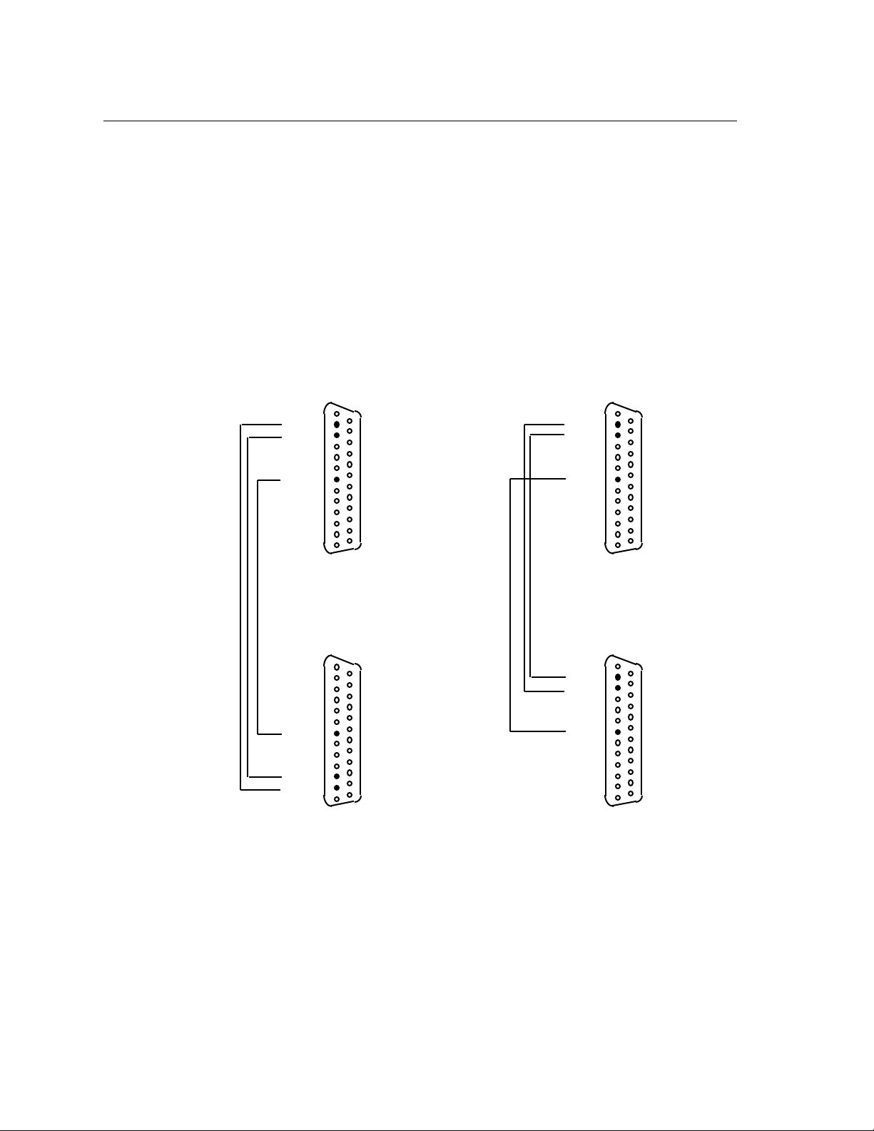
Consideration must be given to the wiring scheme when a device such as a terminal or serial
printer is to be connected to a serial port. The serial ports are considered DTE devices. To
connect the port to another DTE device (such as a VT200 terminal), you will need a crossover
wiring scheme somewhere in the cabling. (Communication between DTE-to-DTE devices
requires a crossover.) To connect the port to a DCE device (such as a modem), straight-through
wiring is required. In the standard Xyplex-supplied modular cabling options, listed in section
3.3.8, signals are directed to the correct pins in the adaptor (for example, the crossover is made
in the DROP adaptor, so that only one type of six-wire cable needs to be used) If you wish to
make your own cables, you must construct the cable with the appropriate wiring scheme.
Figure 3-18 illustrates a simple version of both crossover and straight-through wiring schemes
(this wiring diagram represents the minimum needed to connect a simple terminal).
XMT 2
RCV 3
GND 7
Female Pinouts
GND 7
RCV 3
XMT 2
Male Pinouts
XMT 2
RCV 3
GND 7
Female Pinouts
XMT 2
RCV 3
GND 7
Female Pinouts
Straight Through Cable
Cross Over Cable
Figure 3-18. Crossover and Straight-Through Wiring Schemes.
The crossover cable connects the serial port transmit data (XMT) line to the receive data (RCV)
line of the DTE device. Similarly, the RCV line crosses over to the XMT line of the DTE device.
3-42 0021
Page 41

Chapter 4
Operation and Software Configuration
4.1 Introduction
The terminal server maintains a database of operational parameters (or characteristics), such
as characteristics which allow the unit to communicate on a TCP/IP or LAT network, and
characteristics that specify how the serial ports communicate with devices. (These parameters
can also be maintained in the initialization parameters database). You can configure these
parameters with standard Xyplex TCP/IP-LAT software commands. This chapter describes
how you use the standard commands to configure TCP/IP-related characteristics.
4.2 Logging On to a Port and Obtaining Help
In order to configure the terminal server, you must be logged on to a terminal server serial port
or console port. This section describes how you do this. When your terminal is properly
connected to the terminal server serial port, turn its power ON, then press RETURN (or
ENTER) a few times -- until the terminal server recognizes your device. Note that the
terminal server serial port automatically adjusts to the communication speed of your terminal
(75 bps - 38.4K bps, using 8-bit characters with no parity, or 7-bit characters with even parity;
line speeds higher than 38.4K bps must be set manually). When the terminal server responds,
it generates the following message which appears on your screen:
Welcome to the Xyplex Terminal Server 720
Enter username>
Type in your name, your initials, a nickname -- whatever you would like to be known as while
you are connected, then press RETURN again. You can type up to 16 numbers or letters. This
name helps to identify the port you are on in case you experience a problem. If you choose, you
can change it each time you make a connection to the terminal server. After you enter your
username, the terminal server returns the command prompt:
Xyplex>
The Terminal Server 720 is now ready to accept commands to configure the terminal server
and its ports.
Obtaining Help.
Type HELP and press the RETURN or ENTER key to obtain on-screen information about
terminal server commands.
0021 4-43
Page 42

Operation and Software Configuration
4.3 Configuring TCP/IP Characteristics
Sections 4.5 through 4.7 describes the TCP/IP-LAT software commands that you can use to
configure the Internet-related characteristics for the Terminal Server 720 unit. All of the
commands described in the remaining sections require you to be in "privileged mode," which
is described in the next section.
☞ Xyplex TCP/IP-LAT Software contains many commands which you can use
to configure a Terminal Server 720 terminal server. This Guide does not
cover all of these commands. Rather, this chapter is designed to assist the
user in performing a few of the more commonly-required activities. If you
need more information about the commands available with Xyplex TCP/IPLAT Software, you should order the "TCP/IP-LAT Standard Documentation
Set" from Xyplex. The order code for this set is DOC-CS-001.
4.4 Becoming a Privileged User
To configure Internet-related characteristics and use card management commands for the
Terminal Server 720 unit, you will need to be in "privileged mode." Type the command:
Xyplex> SET PRIVILEGED
and press the RETURN (or ENTER) key. The terminal server will display the following
prompt:
Password>
Type the privileged password for the unit (the factory default is the word SYSTEM, however,
this can be changed by the terminal server manager), and press the RETURN (or ENTER)
key. Note that the port does not display the password as you type it. If you have typed the correct
password, the terminal server will display the following prompt:
Xyplex>>
You can now type the privileged terminal server commands described in the remainder of this
chapter.
☞ For security, you should now change the privileged password, using the DEFINE
SERVER PRIVILEGE PASSWORD command. Use HELP for more information about
this command.
4-44 0021
Page 43

Operation and Software Configuration
4.5 Assigning an Internet Address
To set up the unit to operate as an Internet node, you need to assign values for the SERVER
INTERNET ADDRESS and SERVER INTERNET SUBNET MASK characteristics. The
default for the INTERNET SUBNET MASK characteristic is set up so that the server will
calculate a subnet-mask based on the internet-address that you supply.
The following example shows how you would assign an internet-address for a terminal server
and change the SERVER INTERNET SUBNET MASK characteristic. In this example, the
server internet-address will be set to 128.3.0.100, and the server will be in a class B network.
☞ The following examples show the use of DEFINE commands (which change
parameters in the permanent database) and SET commands (which change
parameters temporarily). Alternatively, you can use only the DEFINE
command and re-initialize the terminal server.
First, specify the internet-address:
Xyplex>> DEFINE SERVER INTERNET ADDRESS 128.3.0.100
Xyplex>> SET SERVER INTERNET ADDRESS 128.3.0.100
(Note that the keyword "SERVER" indicates that the characteristic that you are specifying is a
server-wide characteristic. The keyword "INTERNET" indicates that you are assigning an
Internet-related characteristic. This model is used throughout the command syntax used by
the TCP/IP-LAT software.)
Next, specify the internet-subnet-mask. (By default the internet-subnet-mask will be
automatically calculated, based upon the class of network you specified for the internet-
address. If you later change the internet-address of the server, the internet-subnet-mask is
again re-calculated. You do not need to change internet-subnet-mask if you want the server to
use the internet-subnet-mask that the server calculated. Typically, you would only specify an
internet-subnet-mask if you are using sub-netting.) The following command shows how you
would specify a standard internet-subnet-mask for a class B network.
Xyplex>> DEFINE SERVER INTERNET SUBNET MASK 255.255.0.0
Xyplex>> SET SERVER INTERNET SUBNET MASK 255.255.0.0
If you assign a specific internet-subnet-mask, you should consider disabling the automatic
calculation of the internet-subnet-masks by the server. This will prevent the server from later
re-calculating the internet-subnet-mask if you change the internet-address. To do this, use the
commands:
Xyplex>> DEFINE SERVER INTERNET SUBNET MASK AUTOCONFIGURE DISABLED
Xyplex>> SET SERVER INTERNET SUBNET MASK AUTOCONFIGURE DISABLED
0021 4-45
Page 44

Operation and Software Configuration
4.6 Configuring Domain Name Server Support
To set up the terminal server to operate with a Domain Name Server (such as NIS or the
Berkeley Internet Name Domain Server), you need to assign values for two SERVER
INTERNET characteristics: DOMAIN ADDRESS and DEFAULT DOMAIN SUFFIX. To
allow users to connect to the server via a domain-name, you need to assign a value for the
SERVER NAME characteristic.
The SERVER INTERNET DOMAIN ADDRESS specifies the internet-address at which a
Domain Name Server is located. You can specify up to two Domain Name Servers (primary
and secondary).
The following is an example of how you would specify a default domain-name-suffix
.XYPLEX.COM, and set up the the server to use two Domain Name Servers, which are located at
internet-addresses 128.3.0.200 and 128.3.0.250. Finally, in this example, you will assign the
domain-name TS720.XYPLEX.COM to a terminal server. This procedure assumes that you
already have a working Internet network, and one or more Domain Name Servers. To permit
TCP/IP connections and make services available to users, you may also need to configure your
host systems to support domain-name resolving using tools that are specific to the operating
systems you are using. Refer to the system documentation supplied with the host operating
systems for specific instructions.
☞ The following examples show the use of DEFINE commands (which change
parameters in the permanent database) and SET commands (which change
parameters in the operational database). Alternatively, you can use only the
DEFINE command and re-initialize the terminal server.
First, specify the default domain-name-suffix the server will use to develop fully qualified
domain-names:
Xyplex>> DEFINE SERVER INTERNET DEFAULT DOMAIN SUFFIX .XYPLEX.COM
Xyplex>> SET SERVER INTERNET DEFAULT DOMAIN SUFFIX .XYPLEX.COM
Next, specify the internet-address(es) of any primary and secondary Domain Name Servers:
Xyplex>> DEFINE SERVER INTERNET PRIMARY DOMAIN ADDRESS 128.3.0.200
Xyplex>> SET SERVER INTERNET PRIMARY DOMAIN ADDRESS 128.3.0.200
Xyplex>> DEFINE SERVER INTERNET SECONDARY DOMAIN ADDRESS 128.3.0.250
Xyplex>> SET SERVER INTERNET SECONDARY DOMAIN ADDRESS 128.3.0.250
Optionally, specify the domain-name of the server to allow connections to the server by domain-
name:
Xyplex>> DEFINE SERVER INTERNET NAME TS720.XYPLEX.COM
Xyplex>> SET SERVER INTERNET NAME TS720.XYPLEX.COM
4-46 0021
Page 45

Operation and Software Configuration
The TCP/IP-LAT software also supports limited use of the server to resolve domain-names.
This support does not allow the server to be a general Domain Name Server for the network, but
it does allow the server to resolve domain-names when the server is directly asked to resolve a
domain-name (i.e., the server has been designated to be a primary or secondary name server
for a host or for another server). Typical applications of this support include:
• using one server as the primary or secondary Domain Name Server for other servers in
the network
• using the server to resolve domain-names on a small network that does not use a host for
name serving
• using the server to resolve domain-names in conjunction with the rotary connections
feature.
Upon receipt of a request, the server will examine the domain-name table in the operational
database. The server will send a domain-name response for any domain-names contained in the
database.
To specify domain-names that will be permanently stored by the terminal server, you must first
specify the default-domain-suffix (as described earlier in this section). Then, use the SET and
DEFINE DOMAIN commands to identify names to be resolved by the server. For example, to
specify that the server will resolve the domain-name "HOST1.XYPLEX.COM" with the internet-
address 128.1.2.3, use the commands:
Xyplex>> DEFINE DOMAIN HOST1.XYPLEX.COM 128.1.2.3
Xyplex>> SET SET DOMAIN HOST1.XYPLEX.COM 128.1.2.3
0021 4-47
Page 46

Operation and Software Configuration
4.7 Summary of Internet-Related Commands
The following commands enable you to assign and view the values for Internet addressing that the
terminal server will use.
SHOW/LIST/MONITOR SERVER INTERNET CHARACTERISTICS - This command
displays the current settings for the internet-address, and related internet-address and
domain-name resolution characteristics.
Example:
Xyplex>> SHOW SERVER INTERNET CHARACTERISTICS
DEFINE/SET SERVER - These commands alter the settings for the internet-address, and
related internet-address and domain-name resolution characteristics. Use DEFINE
commands to change parameters in the permanent database and SET commands to change
parameters in the operational database. Alternatively, you can use only the DEFINE
command and re-initialize the terminal server.
INTERNET ADDRESS
Example:
Xyplex>> DEFINE SERVER INTERNET ADDRESS 128.3.0.100
INTERNET
BROADCAST
ADDRESS
Example:
Specifies the Internet address for this terminal server. An
internet-address consists of four numbers separated by
periods (.). Valid values for each of the four numbers are
whole numbers in the range of 1 through 254 (the numbers 0
and 255 are permitted in some circumstances). An
example of an internet-address is: 128.10.2.30. Default:
0.0.0.0. You cannot change this parameter while there are
any active Telnet sessions on this terminal server.
Specifies the Internet address that is used in Internet
Broadcast messages. Some applications can send a message
requesting information to all nodes on an Internet network.
The server uses the broadcast address to determine whether
or not it should respond to such a message. You cannot
change this parameter while there are active Telnet sessions
on this terminal server. Default: 255.255.255.255.
Xyplex>> DEFINE SERVER INTERNET BROADCAST ADDRESS 255.255.255.255
4-48 0021
Page 47

Operation and Software Configuration
INTERNET DEFAULT
DOMAIN SUFFIX
Example:
Specifies the default domain-name specification, which the
terminal server uses to develop a complete (fully-qualified)
domain-name, whenever the user specifies an incomplete
domain-name. The terminal server appends the suffix to the
incomplete domain-name. Specify the domain-name-suffix,
beginning with a period character (.). The domain-name-
suffixes must not end with a period character. Do not enclose
the name in quotation marks. Separate each domain-name
suffix with the vertical bar character (|). The default domain-
name for this characteristic is "" (i.e., the null value).
The maximum total characters of all names together,
including vertical bars '|' and dots '.', cannot exceed 115
characters. The entire command line cannot exceed 132
characters. Each domain-name is limited to a maximum of
50 characters. One of the suffixes may be "no suffixes"
which is specified by a single dot. The keyword NONE
indicates no suffixes.
Example domain-name-suffix list: .XYPLEX.COM|.EDU
Xyplex>> DEFINE SERVER INTERNET DEFAULT DOMAIN SUFFIX .XYPLEX.COM|.EDU
INTERNET PRIMARY
DOMAIN ADDRESS
Specifies the internet-address at which a Domain Name
Server is located. (Domain Name Servers are network hosts
where the server attempts to resolve a domain-name.) The
INTERNET
SECONDARY DOMAIN
ADDRESS
terminal server can use up to two Domain Name Servers
(primary and secondary) to resolve a domain-name. The
terminal server will use the secondary Domain server to
resolve a domain-name if it cannot do so using the primary
Domain server. Default: 0.0.0.0.
Example:
Xyplex>> DEFINE SERVER INTERNET PRIMARY DOMAIN ADDRESS 128.3.0.15
INTERNET PRIMARY
GATEWAY ADDRESS
INTERNET
SECONDARY
GATEWAY ADDRESS
Specifies the internet-address at which a TCP/IP gateway
can be located. The terminal server can use up to two Internet
gateways (primary and secondary) to locate a device on an
external network. The terminal server will first attempt to
use the primary gateway to route a transmission to a remote
device until it determines that the primary gateway has
failed. Then the terminal server will use the secondary
gateway. Default: 0.0.0.0.
0021 4-49
Page 48

Operation and Software Configuration
Example:
Xyplex>> DEFINE SERVER INTERNET PRIMARY GATEWAY 128.3.0.128
INTERNET NAME
Example:
Specifies the domain-name by which the terminal server is
known on the network. The specified domain-name must be a
fully qualified domain-name (i.e., the name will not be
concatenated with the default Internet domain-name-suffix).
Use the following syntax rules to specify a fully-qualified
domain-name: the name can consist of up to 50 ASCII
characters, including the letters A through Z (lower-case
letters are treated as upper-case letters), the numbers 0 through
9, the underscore (_) and hyphen (-) characters. Separate each
segment within a domain-name specification with a period.
The left-most segment identifies the individual network
object. The remaining segments identify the domain where
the object is located. Do not enclose domain-names in
quotation marks ("). Examples of a domain-name are: SRI-
NIC.ARPA or UNIXHOST.ENG.XYPLEX.COM.
Note that a fully qualified domain-name must contain at least
one period.
Xyplex>> DEFINE SERVER INTERNET NAME SERVER720.XYPLEX.COM
4-50 0021
Page 49

Operation and Software Configuration
INTERNET SUBNET
MASK
Specifies the Internet subnet-mask for the terminal server.
The purpose of a subnet-mask is to assist the terminal server
in distinguishing Internet addresses that can be reached
directly from those that must be reached via an IP Gateway.
Each device running TCP protocols contains a subnet mask.
When a user attempts to form a TCP connection with a
destination Internet node, the destination Internet address
is logically ANDed with the subnet mask. The unit's own
Internet address is also logically ANDed with the subnet
mask. The two results of these operations are compared. If
they are equal, then the destination is assumed to be
reachable without the assistance of an IP Gateway. If they
are not equal, then the unit will attempt to reach the
destination via an IP Gateway.
The subnet-mask is defined using the same format as an
Internet address, with ones for the network and/or subnetwork portion(s).
You can also use the AUTOCONFIGURE option to specify
that the software will automatically determined the internet-
subnet-mask. When you allow the terminal server to
automatically determine the internet-subnet-mask, the
terminal server changes the internet-subnet-mask for
either the permanent or operational database whenever the
internet-address changes. AUTOCONFIGURE is the
default. If you plan to use sub-netting in your network, you
should not enable the AUTOCONFIGURE option.
Example:
Xyplex>> DEFINE SERVER INTERNET SUBNET MASK AUTOCONFIGURE ENABLED
Xyplex>> DEFINE SERVER INTERNET SUBNET MASK 255.255.0.0
0021 4-51
Page 50

Chapter 5
SIMM Locations
A Terminal Server 720 can be upgraded with SIMM memory. This allows you to support additional
features, and have more resources available to users. The following figure shows the location of the
SIMM sockets on the Terminal Server 720 card. You will need this information in order to install
or remove SIMMs. Refer to the Installation Instructions supplied with the SIMM kit.
0021 5-52
Page 51
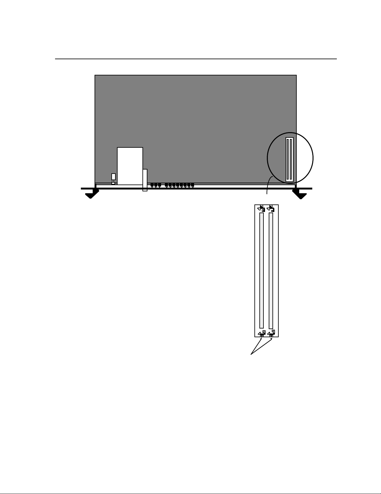
Memory
Card Slot
Network Configuration
(REAR)
1 2
SIMM Sockets
Note: If you add SIMMs, the Terminal Server 720 will detect
that additional memory has been added. However, if you
remove SIMMs, you must update Initialization parameters using
the Initialization Configuration Menu. Refer to Appendix C.
Retainers
E-53
Page 52

Technical Specifications
Item Description
Model 723 I/O Module: Transmit Data, Receive Data,
Terminal Signals
Terminal Cabling Model 723 I/O Module: Modular RJ-45
Transmit Ground, Receive Ground, Data Set Ready/Data
Carrier Detect (DSR/DCD), Data Terminal Ready
(DTR),
Ring/Clear-to-Send (RNG/CTS), and Ready-to-Send
(RTS)
Model 721 and 724 I/O Modules: Transmit Data,
Receive Data, Ground, Data Carrier Detect (DCD), Data
Terminal Ready (DTR), and Ring (RNG/CTS)
Model 721 I/O Module: two 50-pin Telco
Appendix A
Serial Speed Length
Cable Lengths
Memory Card Interface Accepts industry standard JEIDA/PCMCIA
Serial Line Speed 75 to 115.2K bps
Maximum Sessions Per Port
Maximum Sessions Per Unit
Controls Reset push button switch
1
The maximum sessions per unit/port depends on the amount of memory the unit has available.
This varies based on the software features that are enabled. Refer to the TCP/IP-LAT Software
Release Notes for more information.
19.2 Kbps or less 305 meters (1000 feet)
38.4 Kbps 152 meters (500 feet)
57.6 Kbps 60 meters (200 feet)
115.2 Kbps 30 meters (100 feet)
Memory cards.
1
8
1
200
0021 A-1
Page 53

Technical Specifications
Item Description
Memory Base 2 MB DRAM, expandable to 4 MB with two 1 MB
SIMM memory modules.
Environment 10% to 90% humidity, noncondensing, 0° - 45° C
(32° - 113° F)
Model 720 Processor Module:
Power
Typical: +5Vdc - 1.5A
+12 Vdc - 0.0A
-12 Vdc - 0.0A
7W, 23.34 BTU/Hr
Model 721 I/O Module:
Typical: +5Vdc - 1.1A
+12 Vdc - 0.4A
-12 Vdc - 0.4A
15.1W, 50.3 BTU/Hr
Model 723 I/O Module:
Typical: +5Vdc - 1.3A
+12 Vdc - 0.6A
-12 Vdc - 0.6A
20.9W, 69.7 BTU/Hr
Model 724 I/O Module:
Typical: +5Vdc - 1.4A
+12 Vdc - 1.5A
-12 Vdc - 0.6A
29.1W, 72.9 BTU/Hr
Software Xyplex TCP/IP-LAT Software, V4.3 or later
Ethernet Interface Ethernet/IEEE 802.3 Connection provided by Network
9000 Chassis
A-55
Page 54

Appendix B
Order Codes
B.1 Processor and I/O Module Order Codes
Product Name and Description Order Code
Terminal Server 720 processor module N9-720-000
Sixteen-Port I/O module (model 721), N9-000-721
Twenty-Port I/O module (model 723) or N9-000-723
Twenty-four-Port I/O module (model 724) N9-000-724
B.2 Model 723 I/O Module Cabling Order Codes
RJ-45 Straight Through and Crossover Cables
Straight through cable, male RJ-45 to male RJ-45, 7.62 m (25 feet) MX-151-3025
Crossover cable, male RJ-45 to male RJ-45, 7.62 m (25 feet) MX-151-3026
Straight through cable, male RJ-45 to male RJ-45, 3.05 m (10 feet) MX-151-3027
Crossover cable, male RJ-45 to male RJ-45, 3.05 m (10 feet) MX-151-3028
Straight through cable, male RJ-45 to male RJ-45, 0.305 m (1 foot) MX-151-3033
"Octopus" Cables
"Octopus" cable, eight male RJ-45 to one female 50-pin Telco connector, MX-151-3034
1.83 m (6 feet), used to adapt MAXserver 1000 Series cabling to
Xyplex TSERV-Style cabling
"Octopus" cable, 8 male RJ-45 to 1 male 50-pin Telco MX-151-3035
"Octopus" cable, 8 male RJ-45 to 1 male 36-pin Telco DEConnect MX-151-3036
"Octopus" cable, 8 male RJ-45 to 1 female 36-pin Telco DEConnect MX-151-3037
"Octopus" cable, 8 female DB-25 to 50-pin male .915 m (3 feet) MX-151-3085
Telco, "null modem" wired: 1.83 m (6 feet) MX-151-3109
3.05 m (10 feet) MX-151-3095
"Octopus" cable, 8 male DB-25 to 50-pin male .915 m (3 feet) MX-151-3088
Telco, wired "straight-through": 1.83 m (6 feet) MX-151-3098
3.05 m (10 feet) MX-151-3101
15.24 m (50 feet) MX-151-3103
0021 B-56
Page 55

Order Codes
Product Name and Description Order Code
Modular Adaptors
Modular adaptor, female RJ-45 to male DB-25, supporting RING signal,
with red/gray casing MX-350-0179
Modular adaptor, female RJ-45 to male DB-25, supporting
CTS/RTS flow control, with red/gray casing MX-350-0180
Modular adaptor, female RJ-45 to female DB-25 (supports
CTS/RTS flow control), with red/white casing MX-350-0181
Modular adaptor, female RJ-45 to female MMJ connector MX-350-0190
Modular adaptor, female RJ-45 connector to female RJ-45 connector MX-350-0191
Coupling used to connect 2 RJ-45 and/or RJ-12 style modular cables
Modular adaptor, male RJ-45 to female RJ-12, used to adapt MAXserver 1000
Series cabling to TSERV-style cabling MX-350-0197
Modular adaptor, male RJ-45 to female MMJ MX-350-0198
DECconnect Cables
Crossover cable, male RJ-45 to male MMJ, 7.62 m (25 feet; see Figure B-4) MX-151-3032
Crossover cable, male RJ-45 to male MMJ, 3.05 m (10 feet; see Figure B-4) MX-151-3031
Cable-Making Products
Cable, 8-wire, with silver casing (recommended for making cross-over
cables), 305 m (1000 feet) MX-150-0110
Male RJ-45 connectors, quantity 100 MX-170-0399
Crimping tool for RJ-45 male connectors MX-350-0186
Crimping tool for MMJ male connectors MX-350-0194
Conversion kit to convert crimping tool to accept RJ-45 plugs MX-350-0195
Conversion kit to convert crimping tool to accept MMJ plugs MX-350-0196
0021 B-57
Page 56

Order Codes
B.3 Model 721 I/O Module Cabling Order Codes
Product Name and Description Order Code
Distribution Panels and Adaptors
Modular Splitter, 8-Port (requires 1 50-Pin extension cable) MX-151-3083
Modular Splitter, 24-Port (requires 3 50-Pin extension cables) MX-151-3081
Modular Splitter, 8-Port, DEConnect Style, 36-Pin Female MX-151-3061
(requires 1 36-Pin DEConnect Adaptor cable, MX-151-3111)
Modular Splitter, 24-Port, DEConnect Style, 36-Pin Female MX-151-3062
(requires 3 36-Pin DEConnect Adaptor cables, MX-151-3111)
Distribution Panel, 16-Port, Male DB-25 MX-151-3080
(includes 2 six-foot Octopus cables)
Distribution Panel, 16-Port, Male DB-25 with 2 panel-mounted MX-151-3080
50-pin connectors (requires 2 extension cables, MX-151-079)
Distribution Panel (Blank), 16-Port MX-151-3107
(requires 2 six-foot Octopus cables)
Punch Down Block (66M Style) MX-151-3082
(requires 2 50-Pin extension cables)
Gender Changer (Telco 50-Pin, Male-to-Male) MX-151-3090
Extension Cables (Wired Straight Through)
3' Extension, 50-Pin Telco Male-to-Female MX-151-3089
10' Extension, 50-Pin Telco Male-to-Female MX-151-3104
25' Extension, 50-Pin Telco Male-to-Female MX-151-3105
50' Extension, 50-Pin Telco Male-to-Female MX-151-3106
10' Extension, 50-Pin Telco Male-to-Bottom-Entry Female MX-151-3112
25' Extension, 50-Pin Telco Male-to-Bottom-Entry Female MX-151-3116
25' Extension, 50-Pin Telco Male-to-Bottom-Entry Male MX-151-3117
DECconnect Adaptor Cables
6' 50-Pin Telco to 36-Pin female MX-151-3110
8' 50-Pin Telco to 36-Pin male MX-151-3111
25' 50-Pin Telco Male to 36-Pin Bottom-Entry Female MX-151-3063
B-58 0021
Page 57

Product Name and Description Order Code
Octopus Cables
3' 8 Female DB25 Connectors MX-151-3085
6' 8 Female DB25 Connectors MX-151-3109
10' 8 Female DB25 Connectors MX-151-3095
25' 8 Female DB25 Connectors MX-151-3096
50' 8 Female DB25 Connectors MX-151-3097
3' 8 Male DB25 Connectors MX-151-3088
6' 8 Male DB25 Connectors MX-151-3108
10' 8 Male DB25 Connectors MX-151-3101
25' 8 Male DB25 Connectors MX-151-3102
50' 8 Male DB25 Connectors MX-151-3103
Modular Cabling
Order Codes
Cable, 6-wire straight-through, 7.62 m (25'), male RJ-12 to male RJ-12 MX-350-0156
SYS Adaptor, female RJ-12 to female DB-25, Blue and MX-350-0157
Grey (MOD-TAP #06-988-523-30)
DROP Adaptor, female RJ-12 to female DB-25, White and MX-350-0158
Grey (MOD-TAP #06-988-260-20)
0021 B-59
Page 58

Appendix C
Initialization Configuration Menu
C.1 Overview
Each Network 9000 unit provides an Initialization Configuration menu (hereafter referred to as
the "Configuration Menu," or simply the "Menu") that you use to:
• View current settings of initialization parameters. Change the settings when necessary.
• Change the protocol which the unit uses to load parameters.
• Change the protocol which the unit uses to receive a software load image, or change the
name of the load image that it requests.
• Change the protocol which the unit uses to transmit dump files.
• Instruct the operating software, once loaded, to initialize server and port parameters.
• Configure multiple initialization (load/dump) configurations.
The primary objective of the Configuration Menu is to ensure that the unit can load a software
image and its operational parameters. The secondary objective of the Menu is to give the
network manager some flexibility in specifying how the unit loads a software image and its
parameters, as well as provide some backup or redundancy to make sure that the unit can load
in case one of the loading mechanisms is temporarily unavailable. (For example, to specify
which protocols or methods will be used and in which order, or to avoid using one or more
protocols.) To meet these objectives, the Configuration Menu lets you create up to three unique
"load/dump configurations," numbered 1, 2, and 3. (In this case, load refers to loading both
image and parameters.)
If for any reason there are no service offers for loading and/or dumping made as a result of the
first (primary) load/dump configuration, the unit will try the secondary load/dump
configuration. If there are no service offers from that configuration, the unit will try the third
(tertiary) load/dump configuration. If there are still no service offers, the unit will wait and
then try again, beginning with the primary configuration. Only the primary default
load/dump configuration is enabled at the factory.
0021 C-1
Page 59

Configuration Menu
C.1.1 Factory Defaults
The unit is configured at the factory to use a default set of initialization parameters in order to
obtain a software image. This means that, for most configurations, the unit should be able to be
loaded without any configuration changes. Loading is made particularly easy if you have
inserted a memory card which contains the appropriate load image into the Memory Card Slot,
since the unit will load from the memory card. If a card is not present or the appropriate image
is not on the card, the unit requests to be loaded by a host system that has the Xyplex TCP/IPLAT software installed, or a Network 9000 card that has a Memory card which contains the
appropriate load image. (The default order in which protocols are tried is: Memory Card,
Directed TFTP, XMOP, BOOTP/TFTP, MOP, and RARP/TFTP. The flow chart on the next
page depicts the order in which protocols are tried. By default, network load requests are
transmitted on midplane Ethernet LAN segment A.) The unit is also configured at the factory
to store parameters locally on a flash memory card, if one is installed, and remotely at any
properly configured parameter servers.
XMOP is used for loading from a Xyplex load server. MOP is used for loading from a
VAX/VMS host. BOOTP, RARP, and DTFTP (Directed Trivial File Transfer Protocol) are
used for loading from a UNIX host. Typically, you only need to use DTFTP when loading
across a router or when the load host does not support BOOTP or RARP.
0021 C-61
Page 60
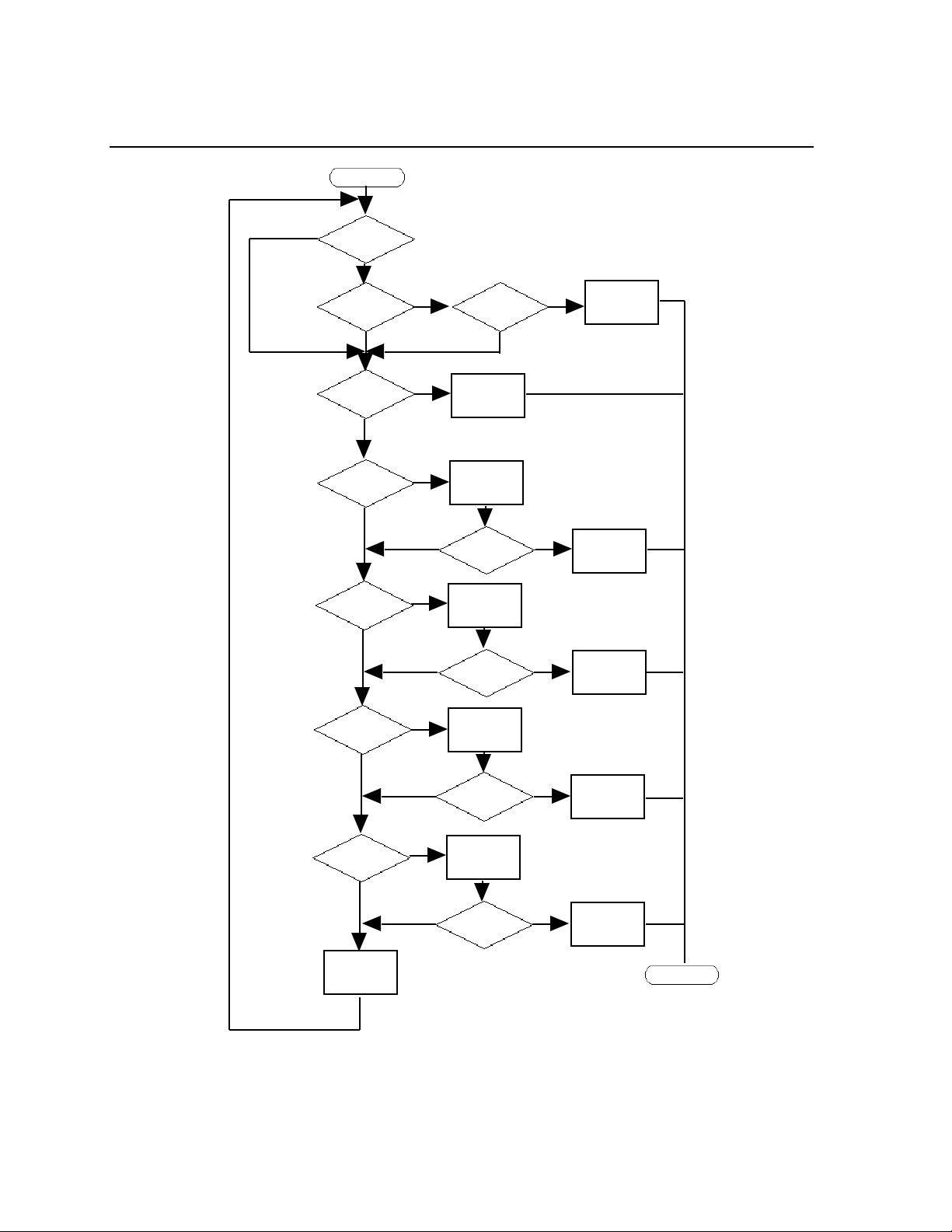
Configuration Menu
Start
No
Load via
Memory Card
Enabled?
Yes
Memory Card
Installed?
No
Load via Directed
TFTP Enabled?
No
Load via XMOP
Enabled?
No
Load via BOOTP/
TFTP Enabled?
No
Yes
Yes
Yes
Yes
No
No
Correct File
Available?
Load File From
TFTP Host
Issue XMOP
Load Request
Load Offers
Received?
Issue BOOTP
Load Request
Load Offers
Received?
Yes
Load File From
Memory Card
No
Evaluate Offers.
Yes
Yes
Load File
From Host.
Evaluate Offers.
Load File
From Host.
Load via MOP
Enabled?
No
Load via RARP/
TFTP Enabled?
No
Go to Next
Initialization
Record
Yes
Yes
Issue MOP
Load Request
No
Load Offers
Received?
Issue RARP
Load Request
No
Load Offers
Received?
Yes
Yes
Evaluate Offers.
Load File
From Host.
Evaluate Offers.
Load File
From Host.
Done
C-62 0021
Page 61

Configuration Menu
C.2 How to Bring Up the Configuration Menu
To access the Configuration menu, follow these steps:
1. Using a straightened paper clip, press the RESET switch once to enter reset mode. (Figure
3-2 shows the location of the switch.) All lights on the front panel should illuminate.
2. Press the RESET switch again, and hold the switch in. With the switch held in, observe the
port lights. The port lights should first go off then light in sequence from 1 to 8. Then port
lights 1 through 4 will go off in sequence. Then all lights will go on and then off again.
When this sequence has completed, release the RESET switch. Next, the unit performs the
standard self-test diagnostics. (The self test requires about 20 seconds to complete.)
3. When the RUN light flashes rapidly (indicating that the self test has completed), autobaud
any serial port by pressing RETURN a few times at a terminal connected to the port. Once
the serial port has selected a port speed, it generates the following message:
Terminal Server, Type 76, Rev x
Ethernet address 08-00-87-00-46-DD, port 1
Configuration in progress. Please wait.
4. Type the password "ACCESS" (note that there is no prompt) and press RETURN. The
menu shown in Figure C-1 appears:
Welcome to the Configuration Menu.
Terminal Server Configuration Menu
1. Display unit configuration
2. Modify unit configuration
3. Initialize server and port parameters
4. Revert to stored configuration
S. Exit saving configuration changes
X. Exit without saving configuration changes
Enter menu selection [X]:
Figure C-1. Example Terminal Server Configuration Menu
0021 C-63
Page 62

Configuration Menu
If the menu does not appear, you might see one or more of the following warning messages:
(1) WARNING: Stored configuration data is invalid; using defaults
Press any key to continue
(2) WARNING: Stored configuration data is corrupt; using defaults
Do you wish to preserve any existing server and port parameters (Y/N) [N]?
(3) WARNING: Configuration data not accessible; retry (Y/N) [Y]?
Message 1 -- indicates that the Terminal Server 720 has accessed configuration information in the
chassis Control Storage, which has a valid checksum, but pertains to a different module type. This
message appears when you have replaced another Network 9000 module type with a Terminal
Server 720. For example, the message will appear if you replace a managed 10Base-T/10Base-FL
concentrator or bridge/router module with a Terminal Server 720.
Press any key to bring up the configuration menu. The Terminal Server 720 will use the initial
default configuration as the basis for any additional changes you make. Select option S from the
configuration menu to replace the previous (invalid) configuration information.
Message 2 -- indicates that the Terminal Server 720 has accessed configuration information in the
chassis Control Storage, but that the data is corrupt (i.e., the checksum is invalid.)
If the Terminal Server 720 currently has operational parameters stored on a parameter server or
memory card, answer Y to the prompt that follows; the Terminal Server 720 will retrieve the stored
parameters when you re-initialize the card. Do not answer Y to the prompt unless there are
parameters stored on a parameter server or memory card; if the Terminal Server 720 cannot find
a parameter file, the module will search for it indefinitely.
Answer 'N' to the prompt if no parameters are available at a parameter server. In this case, the
module will use default parameters when you re-initialize the card. Do not answer No to the
prompt if parameters are stored at a parameter server; if you do so, the module will search for and
destroy any parameter files that are stored by parameter servers1.
Message 3 -- indicates that the Terminal Server 720 cannot access configuration information in
the Control Storage of the Network 9000 chassis. Typically, this means that the Management Bus
of the chassis is very busy -- perhaps because someone has established a CHASSIS CONSOLE
session. However, on rare occasions, this message might indicate that the chassis Control Storage
has become defective.
If the configuration information remains inaccessible after multiple retries, call your Xyplex
support representative. (In the U.S. and Canada, call 1-800-435-7997. For international calls, the
number is +508-264-9903.)
1
(using option X). Then, access the menu again and enter the correct response.
If you inadvertently answer this prompt incorrectly, exit from the configuration menu without saving changes
C-64 0021
Page 63

Configuration Menu
C.3 Terminal Server Configuration Menu Options
At the "Enter menu selection" prompt of the Terminal Server Configuration Menu, type the
number corresponding to the configuration action you want to perform, then press RETURN.
(The default choice is X -- exiting without saving configuration changes.) The following list
describes each of the options. Each option is described in more detail in a subsequent section.
Option Description
1. Display unit
configuration
2. Modify unit
configuration
3. Initialize server and
port parameters
4. Revert to stored
configuration
S. Exit saving
configuration changes
View a list of both the previously-stored configuration values
and the values that will be used after you exit from the menu
(using Option S -- "Exit saving configuration changes").
Change the method by which the unit loads its software; change
the name of the load image that it requests, if any; change the
method by which the unit requests parameter service and dumps
memory; specify the total configured memory; and
enable/disable load status messages.
Instruct the operating software, once loaded, to use factory
default values for all server and port parameters. All current
server and port parameters will be lost when you exit from the
menu (using Option S "Exit saving configuration changes").
Cancel any changes you have made without exiting from the
menu. The unit reverts to the configuration values that were
last saved. Typically, you would select this option if you had
changed some settings, and then decided to undo the changes
and begin again.
Exit from the menu and store the changes that you have made.
X. Exit without saving
configuration changes
Exit from the Configuration menu without saving the
configuration changes that you have made (i.e., use the
configuration that was last saved).
The dialog associated with each menu choice is described in the sections that follow. After you
exit from the Terminal Server Configuration Menu, the unit loads software and parameters.
For each prompt shown in the Terminal Server Configuration Menu, the default choice is
shown in square brackets, [ ]. For example, [A] indicates that "A" is the default choice for a
prompt. Press RETURN to select the default choice.
For many prompts, the default value for the prompt can change. The first time you run the
Terminal Server Configuration Menu, the default value shown is the factory default value.
After you exit from the Terminal Server Configuration Menu, having saved changes, the
default value shown for a prompt is the currently-stored value, not the factory default value.
0021 C-65
Page 64

Configuration Menu
C.3.1 Option 1 - Display Configuration
To select this option, answer 1 to the "Enter menu selection" prompt of the Terminal Server
Configuration Menu. The dialog displays a Display Unit Configuration Menu, which is
shown in Figure C-2:
Display Unit Configuration Menu
1. Load/dump configuration #1 (Enabled)
2. Load/dump configuration #2 (Disabled)
3. Load/dump configuration #3 (Disabled)
M. Miscellaneous unit configuration
X. Exit to main menu
Enter menu selection [X]:
Figure C-2. The Display Unit Configuration Menu.
Display Unit Configuration Menu - Choices 1, 2, and 3.
If you select choices 1, 2, or 3 of the Display Unit Configuration Menu, the menu will display a
list of currently stored configuration values and the new configuration values for the specified
load/dump configuration. This display is similar to the list shown in Figure C-3.
Stored Configuration New Configuration
Status: Enabled Enabled
Image load method: CARD XMOP MOP BOOTP RARP CARD XMOP MOP BOOTP RARP
Parameter load method: CARD XMOP MOP BOOTP RARP CARD XMOP MOP BOOTP RARP
Dump method: XMOP MOP BOOTP RARP XMOP MOP BOOTP RARP
CARD/XMOP/MOP filename: XPCSRV20 XPCSRV20
Default unit IP addr: 0.0.0.0 0.0.0.0
DTFTP host IP addr: N/A N/A
DTFTP gateway IP addr: N/A N/A
DTFTP filename: N/A N/A
Network interface: Segment A Segment A
(Type any key to continue)
Figure C-3 (part 1 of 2). Sample Unit Configuration Display
C-66 0021
Page 65

Configuration Menu
Stored Configuration New Configuration
Status: Disabled Disabled
Image load method: N/A N/A
Parameter load method: N/A N/A
Dump method: N/A N/A
CARD/XMOP/MOP filename: N/A N/A
Default unit IP addr: N/A N/A
DTFTP host IP addr: N/A N/A
DTFTP gateway IP addr: N/A N/A
DTFTP filename: N/A N/A
Network interface: N/A N/A
(Type any key to continue)
Figure C-3 (part 2 of 2). Sample Unit Configuration Display.
Figure C-3, part 1 depicts how this display might appear for an enabled load/dump configuration
(the values shown here are those of the factory default load/dump configuration). Figure C-3,
part 2 depicts how this display might appear for a disabled load/dump configuration.
The DTFTP (Directed Trivial File Transfer Protocol) information is present when DTFTP is
listed as an Image load method. (Typically, you only need to use this when loading across a
router or when the load host does not support BOOTP or RARP.) Similarly, the CARD/XMOP/
MOP load filename is present when CARD, XMOP, or MOP is listed as an Image load method.
Press any key; the unit returns you to the Display Unit Configuration Menu (Figure C-2).
Display Unit Configuration Menu - Choice M.
If you select choice M of the Display Unit Configuration Menu, the menu will display a a list .
This display is similar to the list shown in Figure C-4.
Stored Configuration New Configuration
Load status messages: Enabled Enabled
Memory installed: 2 Megabytes 2 Megabytes
(Found 2 Megabytes)
(Type any key to continue)
Figure C-4. Sample Miscellaneous Configuration Display
Press any key; the unit returns you to the Display Unit Configuration Menu (Figure C-2).
0021 C-67
Page 66

Configuration Menu
Display Unit Configuration Menu - Choice X.
If you select choice X of the Display Unit Configuration Menu you will be returned to the
Terminal Server Configuration Menu (Figure C-1).
C.3.2 Option 2 - Modify Unit Configuration
To select this option, answer 2 to the "Enter menu selection" prompt of the Terminal Server
Configuration Menu. The menu display a Display Unit Configuration Menu, which is shown
in Figure C-5:
Modify Unit Configuration Menu
1. Load/dump configuration #1 (Enabled)
2. Load/dump configuration #2 (Disabled)
3. Load/dump configuration #3 (Disabled)
M. Miscellaneous unit configuration
D. Set unit configuration to defaults
X. Exit to main menu
Enter menu selection [X]:
Figure C-5. The Modify Unit Configuration Menu.
Modify Unit Configuration Menu - Choices 1, 2, and 3.
If you select choices 1, 2, or 3 of the Modify Unit Configuration Menu, the menu prompts one of
the following (depending on which number load/dump configuration you choose to modify):
Initialize load/dump configuration #1 to defaults (Y,N) [N]?
Initialize load/dump configuration #2 to defaults (Y,N) [N]?
Initialize load/dump configuration #3 to defaults (Y,N) [N]?
Valid answers to this prompt are Y (Yes) and N (No).
• If you answer ‘Y’, the unit returns all configuration options to their factory default values,
which are (Initialization Configuration 1 only; Configurations 2 and 3 are disabled):
Parameter load method: CARD, XMOP, MOP, BOOTP, RARP
Image load method: CARD, XMOP, MOP, BOOTP, RARP
Dump Method: XMOP, MOP, BOOTP, RARP
CARD/XMOP/MOP load filename: XPCSRV20
Default unit IP address: 0.0.0.0
Directed TFTP values 0.0.0.0 or N/A
Network Interface Segment A
C-68 0021
Page 67

Configuration Menu
The menu prompts one of the following (depending on which number load/dump
configuration you choose to modify):
Enable load/dump configuration #1 (Y,N) [Y]?
Enable load/dump configuration #2 (Y,N) [Y]?
Enable load/dump configuration #3 (Y,N) [Y]?
Valid answers to this prompt are Y (Yes) and N (No). If you answer this prompt Y, the unit
enables the specified load/dump configuration. If you answer this prompt N, the unit
disables the specified load/dump configuration. After answering the prompt, the menu
displays the message "Type any key to continue”. Press any key; the unit returns you to
the Modify Unit Configuration Menu (Figure C-5)
• If you answer No to the “Initialize load/dump configuration (#1, #2, or #3) to defaults?”
prompt, the configuration menu generates a series of prompts which are described in the
following steps.
1. The configuration menu prompts:
Enable ALL methods for image loading (Y,N) [N]?
Valid answers to this prompt are:
Y -- Use any software loading method: CARD (Memory card), DTFTP (Directed
Trivial File Transfer Protocol), XMOP (Xyplex proprietary protocol), MOP (DEC
Maintenance Operations Protocol), BOOTP (Bootstrap Protocol), RARP (Reverse
Address Resolution Protocol). Note that host setup activity is required for MOP,
BOOTP, and RARP protocols.
N -- Use specific method(s)).
a. If you answer Y, proceed to Step 2.
b. If you select N, the configuration menu prompts:
Toggle (CARD,DTFTP,XMOP,MOP,BOOTP,RARP) image load methods [C,D,X,M,B,R]:
Valid answers to this prompt are C (Memory card), D (Directed Trivial File Transfer
Protocol), X (Xyplex Proprietary protocol), M (DEC MOP loader), B (BOOTP) or R
(RARP). You can select up to six methods.
Selecting C enables the unit to load software from a Memory card. Selecting D enables the
unit to load via directed TFTP. Selecting X enables the Terminal Server 720 to load from a
Xyplex MAXserver Manager or at another Network 9000 module which has a memory
card. Selecting M enables the unit to load software via the DEC MOP loader protocol.
Selecting B enables the unit to load software from a BOOTP host. Selecting R enables the
unit to load software via RARP.
0021 C-69
Page 68

Configuration Menu
Select specific protocol(s) by removing letters from or adding letters to the brackets. To
remove a letter, type the letter and press RETURN. The prompt reappears; however, the
letter you typed does not appear within the brackets. To add a letter to those within the
brackets, type the letter and press RETURN. The prompt reappears and the letter you typed
is included within the brackets.
When the letters within the brackets represent all the protocols you want to use, press
RETURN.
2. The configuration menu prompts:
Enable ALL methods for parameter loading (Y,N) [Y]?
Valid answers to this prompt are:
Y -- Use any parameter loading method: XMOP (Xyplex proprietary protocol), MOP (DEC
Maintenance Operations Protocol), BOOTP (Bootstrap Protocol), RARP (Reverse Address
Resolution Protocol)
N -- Use specific method(s)).
a. If you answer Y, proceed to Step 3.
b. If you select N, the configuration menu prompts:
Toggle (CARD,XMOP,MOP,BOOTP,RARP) parameter load methods [C,X,M,B,R]:
Valid answers to this prompt are C (Memory card), X (Xyplex Proprietary protocol), M
(DEC MOP loader), B (BOOTP) or R (RARP). You can select up to four parameter
loading methods.
Selecting C enables the unit to store and load parameters from a Memory card. Selecting X
enables the Terminal Server 720 to store and load parameters at a Xyplex MAXserver
Manager or at another Network 9000 module which has a memory card. Selecting M
enables the unit to store and load parameters via the DEC MOP loader protocol. Selecting B
enables the unit to store and load parameters at a BOOTP/TFTP host. Selecting R enables
the unit to store and load parameters via RARP/TFTP.
Select specific protocol(s) by removing letters from or adding letters to the brackets. To
remove a letter, type the letter and press RETURN. The prompt reappears; however, the
letter you typed does not appear within the brackets. To add a letter to those within the
brackets, type the letter and press RETURN. The prompt reappears and the letter you typed
is included within the brackets.
When the letters within the brackets represent all the protocols you want to use, press
RETURN.
C-70 0021
Page 69

Configuration Menu
3. The configuration menu prompts:
Enable ALL methods for dumping (Y,N) [Y]?
Valid answers to this prompt are:
Y -- Use any dumping method: XMOP (Xyplex proprietary protocol), MOP (DEC
Maintenance Operations Protocol), BOOTP (Bootstrap Protocol/Trivial File Transfer
Protocol (TFTP)), RARP (Reverse Address Resolution Protocol/TFTP)
N -- Use specific method(s).
a. If you answer Y, proceed to Step 5.
b. If you select N, the configuration menu prompts:
Toggle (XMOP,MOP,BOOTP,RARP) dump load methods [X,M,B,R]:
Valid answers to this prompt are X (Xyplex Proprietary protocol), M (DEC MOP loader), B
(BOOTP) or R (RARP). You can select up to four methods. The prompt appears again after
you enter your selection, enabling you to enter another dumping method. Press RETURN
to proceed to the next prompt.
Selecting X enables the unit to dump its memory contents to a Xyplex MAXserver Manager
when a crash occurs (you cannot enable dumping to a flash memory card). Selecting M
enables the unit to dump memory via the DEC MOP loader protocol. Selecting B enables
the unit to dump memory at a BOOTP host. Selecting R enables the unit to dump memory
via RARP.
4. If you have selected the CARD, XMOP, or MOP loading method(s), you will see the
following prompt. (If you do not see this prompt, proceed to Step 5.)
CARD/XMOP/MOP image filename (16 characters max) [XPCSRV20]:
This prompt requests the CARD/XMOP/MOP load file name. There are two types of valid
answers to this prompt -- file names or numerical values. Valid file names consist of up to
16 characters, which can be letters and numbers, the underscore character (_), the hyphen
character (-), and the period (.) character. The default load file name is XPCSRV20. (The
actual name of the load file is XPCSRV20.SYS.) In the default load filename (XPCSRV20),
the .SYS suffix is implicit.
In place of a filename, you can specify a numerical values. A numerical value specifies to
a Xyplex loader (another Network 9000 card with a memory card installed, or a MAXserver
Manager card) that it should determine the appropriate load file based on:
• The requesting unit's hardware type, or:
• A node entry in the client database of a MAXserver loader or another Network 9000 unit.
0021 C-71
Page 70

Configuration Menu
You can also use numerical values to specify that a MOP (Maintenance Operations
Protocol) loader is to determine the appropriate load file based on information contained in
the NCP (Network Control Program) database.
Valid numerical values consist of the pound-sign character (#) and a number in the range
of 0 through 128. Xyplex load servers respond to the numbers #1 through #5. The default
numerical value is #1. The numerical value #1 allows you to specify a load file name via
the NCP commands at a VAX/VMS load server, or via client entries on a MAXserver
loader or Network 9000 Card with a Memory card. Numerical values #2 through #4 are
reserved for use by Xyplex. The numerical value #5 requires a Xyplex load server, which
can be a Network 9000 card with a Memory card or a MAXserver Manager card
(MAXMAN), to ignore the load request -- unless the load server's client database contains
a node entry for the requesting terminal server. (The numerical value #5 is useful when
you want to require that a specific Xyplex load server be used to load the unit.) Numerical
values #6 through #128 are currently undefined.
Type your answer and press RETURN.
5. If Directed TFTP is enabled, the following prompts appear:
Enter unit IP address [0.0.0.0]:
Enter the Internet address of the Terminal Server 720 unit, or press RETURN to accept
the default address, 0.0.0.0. You must supply a non-zero Internet address if (in step 1)
you have specified all image loading protocols or Directed TFTP (DTFTP) as an
image loading method.
Enter host IP address [0.0.0.0]:
Enter the Internet address of the load host, or press RETURN to accept the default
address, 0.0.0.0. You must supply a non-zero Internet address if if (in step 1) you have
specified all image loading protocols or Directed TFTP (DTFTP) as an image loading
method.
Enter gateway IP address [0.0.0.0]:
If the load host is not on the same network as the unit, enter the Internet address of a
gateway.
Enter TFTP load filename []:
Enter the name of the file to load (max. 64 characters)
C-72 0021
Page 71

Configuration Menu
6. The configuration menu prompts:
Select network interface segment (A,B,C) [A]:
Specify which Ethernet network interface segment to which the Terminal Server 720
shall be attached. Valid answers are A, B, or C. After you have selected a segment and
pressed the RETURN key, the menu will prompt:
(Type any key to continue)
Press any key; the unit returns you to the Modify Unit Configuration Menu (Figure C-5).
Modify Unit Configuration Menu - Choice M.
If you select choice M of the Modify Unit Configuration Menu, the menu prompts:
Display Load status messages (Y,N) [Y]:
It might be necessary to prevent the unit from generating status messages during the software loading
process, if a device such as a bar code reader, which cannot interpret status messages, is connected to a
serial port. To disable load status messages, enter ‘N’. Otherwise, leave the default (Y) intact.
The configuration menu prompts:
Total installed memory in megabytes (2,4) [2]:
The prompt indicates the amount of installed memory for which the unit has been configured.
If you remove memory, you must change this value. (Preferably, you should change this value
before you remove the memory.) Also, if you have enabled more software features than the unit
can support with the reduced memory, you will not be able to re-initialize the unit after you
remove the SIMMs. If this happens, you must re-install the SIMMs and configure the TCP/IPLAT software image for fewer features.
SIMMs should only be installed or removed by qualified personnel. Refer to the Installation
Instructions supplied with your SIMM kit on how to install and remove SIMM memory
modules2.
The unit automatically detects added memory. Therefore, you do not need to increase the
"installed memory" value when you install additional memory. If you choose to increase the
value anyway, do not do so before you install the additional memory. If you do, the unit will
generate the following warning message:
WARNING: After saving the new configuration, you must turn the
unit off and install the additional memory specified (x MB).
2
The order code for for a 2 MByte SIMM memory upgrade kit is MX-500-5744.
0021 C-73
Page 72

Configuration Menu
(This message appears only while you are using the Configuration menu.)
In addition, you will be prompted to turn off the unit and install the memory if you attempt
to exit the Configuration menu, saving changes (Option S). Also, the front panel lights will
flash an error code the next time the unit is initialized, if you have not yet installed the
memory.
The configuration menu prompts:
(Type any key to continue)
Press any key; the unit returns you to the Modify Unit Configuration Menu (Figure C-5).
C-74 0021
Page 73

Configuration Menu
Modify Unit Configuration Menu - Choice D.
If you select choice D of the Display Unit Configuration Menu, you will be prompted:
Initialize ALL configuration data for this unit to defaults (Y,N) [N]?
Valid answers are Y (Yes) or N (No). If you answer Y, all load/dump configurations and
miscellaneous settings (load messages enabled/disabled and amount of installed memory)
will be returned to their factory default settings. If you answer N, they will not be returned to
their factory default settings. After you have answered Y or N, the menu will prompt:
(Type any key to continue)
Press any key; the unit returns you to the Modify Unit Configuration Menu (Figure C-5).
If you answered Y, and the load/dump configurations and miscellaneous settings were
already at their factory default settings, you would see the message:
Configuration is already set to defaults
Modify Unit Configuration Menu - Choice X.
If you select choice X of the Display Unit Configuration Menu you will be returned to the
Terminal Server Configuration Menu (Figure C-5).
0021 C-75
Page 74

Configuration Menu
C.3.3 Option 3 - Initialize server and port parameters
To select this option, answer 3 to the "Enter menu selection" prompt of the Terminal Server
Configuration Menu (Figure C-1). The server prompts:
When the software has been loaded, should
default server and port parameters be used (Y,N) [N]?
Valid answers are Y (yes) and N (no). Type your answer and press RETURN; the unit
returns you to the Configuration menu.
The parameter initialization takes effect after you exit from the Configuration menu and the
unit loads its image (assuming that you specify that the unit should save the changes -- Option
S). Changes you have made through the ROM Configuration menu take place after you exit
from the menu.
If you decide that you do not want to revert to the initial values, you can again select Option 3
from the Configuration menu, and answer No to the preceding prompt, or exit without saving
the changes (i.e., select Option X).
C.3.4 Option 4 - Revert to stored configuration
To select this option, answer 4 to the "Enter menu selection" prompt of the Terminal Server
Configuration Menu (Figure C-1). The configuration menu prompts:
Revert to the stored configuration (Y,N) [N]? y
Valid answers are Y (Yes) and N (No). If you answer No, the unit returns you to the
Configuration menu. If you answer Yes, the unit displays the messages:
Configuration reset to stored values.
(Type any key to continue)
Press any key; the unit returns you to the Configuration menu (Figure C-1). You can then exit
from the Configuration menu using Option S or X.
C-76 0021
Page 75

Configuration Menu
C.3.5 Option S - Exit Saving Configuration Changes
To select this option, answer S to the "Enter menu selection" prompt of the Terminal Server
Configuration Menu (Figure C-1). If you have made any changes, the configuration menu
prompts:
Save changes and exit (Y,N) [Y]?
If the unit is configured to store parameters locally, you see this message:
Updating configuration data; please wait...
If you have not made any changes, the configuration menu displays:
No changes made. Exit Configuration menu (Y,N) [Y]?
To exit from the Configuration menu, press RETURN. If you do not want to exit from the
menu, type 'N' and press RETURN; the Configuration menu appears.
C.3.6 Option X - Exit Without Saving Configuration Changes
To select this option, answer X to the "Enter menu selection" prompt. If you have made
changes, the configuration menu prompts:
Exit without saving changes (Y/N) [N]?
Valid answers to this prompt are Y (Yes) and N (No). To exit the Configuration menu, type
'Y' and press RETURN. If you do not want to exit from the menu, simply press RETURN;
the Configuration menu appears.
If you have not made any changes, the configuration menu displays:
No changes made. Exit Configuration menu (Y,N) [Y]?
To exit from the Configuration menu, press RETURN. If you do not want to exit from the
menu, type 'N' and press RETURN; the Configuration menu appears.
0021 C-77
Page 76
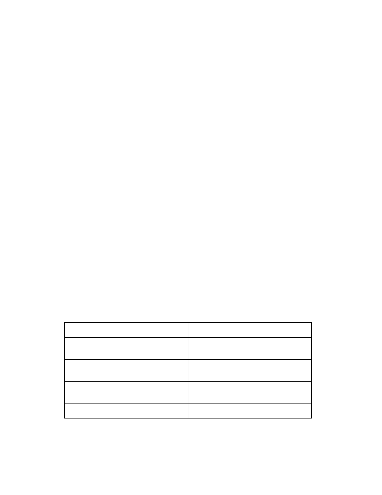
Appendix D
Troubleshooting
D.1 Overview
Refer to this chapter if you experience a problem with your terminal server. This chapter
describes:
• Normal terminal server operations
• How the terminal server indicates errors
• How to reset the terminal server
• What to do if the Ethernet (A, B, or C) light on the front panel goes out
• How to Troubleshoot Internet Software Loading Problems
D.2 Normal Terminal Server Operations
The terminal server automatically runs self tests when you apply power to the unit or use the
RESET button to initialize the unit. Upon successful completion of the self tests, the terminal
server loads software from a memory card, or over the network from a load server.
During the self test and software loading, the lights (LEDs) on the front panel flash to
reflect various types of activity. During self-test, you should observe the following light
activity:
Front Panel Light Activity Meaning
All lights ON Testing lights (approximately 1
second).
CARD, RUN, CON, A, B, and C
(Ethernet) lights OFF
Lights ON, from right (8 status light) to
left (1 status light)
RUN flashes rapidly Successful completion of Self Test.
When the Self Test completes, the terminal server begins loading software.
Self Test begins.
Self Test is running.
0021 D-1
Page 77

Troubleshooting
The Ethernet (A, B, or C) light on the front panel (see Figure D-2) illuminates as soon as the
terminal server detects network activity (normally about 2 seconds). Within 15 seconds
the unit transmits software load requests on the network or begins to load from the memory
card.
The RUN light and the Ethernet (A, B, or C) light blink during loading. Loading takes
from ten to sixty seconds, depending on the amount of network activity and the speed of the
load server. The light pattern should appear as follows:
Front Panel Light Activity Meaning
Ethernet A, B, or C light ON Terminal server detects network activity
on Ethernet segment to which it is attached.
CARD light ON Unit is loading from a Memory card (light
ON for approximately 15 seconds).
☞ The Terminal Server 720 is
accessing the Memory card. Do not
remove the card while the CARD light
is ON.
RUN and Ethernet (A, B, or C) lights blink
simultaneously
When loading from a memory card, or
when using another Network 9000 card as a
load server, Port lights go ON, sequentially
from right (Port 8 status light) to left (Port 1
status light). Then, lights go OFF.from left
to right.
RUN light flashes slowly
Ethernet (A, B, or C) light flashes when
Ethernet packets are received
Software load in progress.
Unit has finished loading the software
image, and is decompressing it.
Software loading has completed.
Terminal server is in normal operating
state.
0021 D-79
Page 78

Troubleshooting
D.3 Startup Error Codes
If front panel lights do not behave as described in Section D.2 when you power up or initialize
the Terminal Server 720, the unit might be displaying an error code. A special pattern of
diagnostic codes indicate that a hardware or software error has occurred.
When a startup error occurs:
1. The port lights flash 10 times quickly.
2. One or more port lights illuminate (this is the first pass error code).
3. All port lights flash sequentially.
4. One or more lights illuminate (this the second pass error code).
This sequence repeats. Figure D-1 illustrates the self test error code sequence.
D-80 0021
Page 79
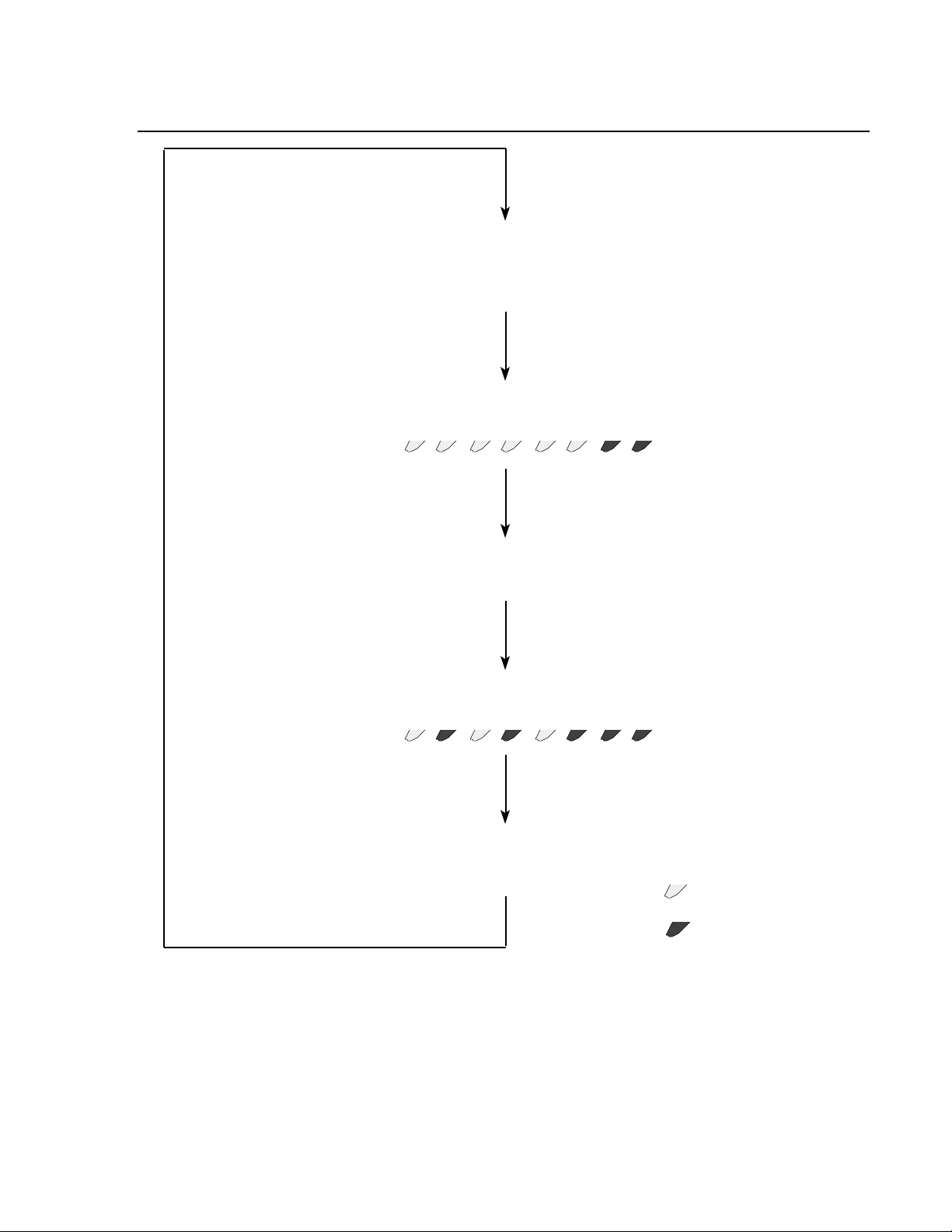
....................................................
1 2 3 4 5 6 7 8
....................................................
1 2 3 4 5 6 7 8
Self-test failure
occurs. LEDs
flash 10 times,
very quickly.
Sequence
repeats
continuously
User records
error code 78
User records
error code 24678
First Error Code
Second Error Code
LEDs flash
sequentially
= Off
= On
Troubleshooting
Write down the numbers of the first and second pass error codes (the lights that are ON) and
contact your Xyplex Customer Support 1-800-435-7997 (U.S.A) or +508-264-9903 (International).
Your representative will provide further instructions on how to handle the condition.
0021 D-81
Figure D-1. Self Test Error Code Sequence
Page 80

Troubleshooting
Common Error Codes
If you see this error code, the Terminal Server 720 has been configured for more memory than
is actually installed:
First Pass 3, 4, 6, 7
Second Pass 3
To correct the error, you must either configure the server for less installed memory, using the
Initialization Configuration menu, or install additional SIMM memory. (The SIMM
memory installation should only be performed by qualified personnel.) The Configuration
menu is described in Chapter 4. Use Option 2, Modify Unit Configuration, to specify the
amount of installed memory.
If you see one of these error codes, you must use the Initialization Configuration menu to reinitialize the unit:
First Pass 3, 4, 8
Second Pass 2, 8
or
First Pass 3, 4, 6, 7
Second Pass 3, 6
Appendix C explains how to access the Initialization Configuration menu. Select Option 2,
Modify Unit Configuration, from the menu.
If you see the following error code during operation, the control storage for the slot in which the
terminal server is installed is corrupted. This is different from normal error code display in that
it is not fatal (i.e., normal port, Local Management Bus, and network activities are maintained).
First Pass 3, 4, 6, 7
Second Pass 1, 2, 3, 4, 5, 6, 7, 8
The fault can be corrected remotely by having a network manager issue one of the Network
9000 DEFINE CHASSIS SLOT commands which affects the initialization records.
Afterwards, the error code goes is no longer displayed and normal LED activity resumes
(flashing RUN and segment LEDs, port activity, etc).
D-82 0021
Page 81

Troubleshooting
D.4 Loading Messages
If you press RETURN at a terminal connected to a serial port during the first minute after the
unit is powered up (after the self test has completed), network loading messages will be
displayed. If you want to see the sequence of message responses that occur during the load
process, follow the steps in Section D.4.1 after power on. (Note that when the Terminal Server
720 is loading from a Memory card, you do not see any messages, and you cannot access the
terminal server.)
D.4.1 Example Network Load Procedure
The following example load procedure assumes that a terminal is physically connected to a
serial port and that the unit is loading software from the network. Press RETURN every 5 - 10
seconds to observe all of the message types.
Complete these steps:
1. Power-up the terminal and press RETURN several times to autobaud the port to the baud rate of
the terminal. Type any character (except the RETURN key or the CTRL-T command); the port
light should go out. (This exercise is useful when debugging cables.) If the server appears to
have selected a port speed (LED goes on), but you do not see any response when you press the
RETURN key, type the BREAK character to re-initialize the port autobaud sequence, then press
RETURN several times.
2. Observe a message similar to the following one:
Terminal Server, Type 76, Rev x.xx.x
Ethernet address 08-00-87-xx-xx-xx, port x
Initializing...
This message appears for approximately 10 seconds. You can compare the Ethernet
address displayed with the equipment label on the unit.
3. Next, several messages similar to the following appear:
Terminal Server, Type 76, Rev x.xx.x
Ethernet address 08-00-87-xx-xx-xx, port x
Requesting network load service
Only the last line is different. This message lasts for approximately 20 to 60 seconds (20
seconds for each load/dump configuration that you have enabled; there is no indication
that the unit is trying another load/dump configuration - the message stops when a service
offer is received). If you do not receive the next message after this time elapses, you are not
configured on a load server. Install software on a load server using the procedures
described in the Software Installation Guide supplied with your software kit.
0021 D-83
Page 82

Troubleshooting
4. Next, you should observe a message similar to the following:
Terminal Server, Type 76, Rev x.xx.x
Ethernet address 08-00-87-xx-xx-xx, port x
Evaluating service offers
If you typed a CTRL-T after a port speed had been selected, a message similar to the following
appears:
Received load service offers:
Host Address protocol merit filename
xx-xx-xx-xx-xx-xx 0809 9C000037 XPCSRV20
One to ten load server addresses are displayed. The terminal server selects the load server
with the highest merit value. If two or more load servers have the same merit value, the
terminal server selects the first load server listed. The load server selection algorithm
proceeds to find the load server with the highest merit value that is on line. After checking
the list of servers, the cycle repeats until a load server responds.
5. After the load server is chosen, and has responded, several messages similar to the following
appear:
Terminal Server, Type 76, Rev x.xx.x
Ethernet address 08-00-87-xx-xx-xx, port x
Loading over Link L1 from server AA-00-04-00-D1-04, message 554
These responses indicate the load server from which the terminal server is loading and the
message number the unit has received.
6. After the server has successfully completed loading, press RETURN. The server displays
the logon prompt:
Welcome to the Xyplex Terminal Server
Enter username> _
D-84 0021
Page 83
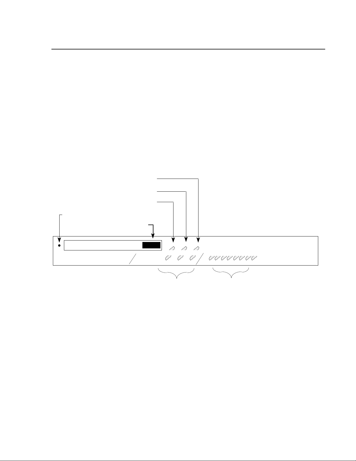
Troubleshooting
CARD RUN CON
C
Serial Port
Status Lights
Ethernet Segment
Indicator Lights
Memory Card Drive Status Light
720 Card Status Light
Console Port Status Light
Reset Switch
.....................................................................................................................................................
2 3 4 5 6 71 8
A B
Memory Card Eject Button
D.5 Resetting the terminal server
You can reset the Terminal Server 720 to force it to run a self test or to re-initialize the unit. All
connections are terminated when you reset the unit.
To reset the terminal server, follow these steps:
1. Make a simple "tool" from an ordinary paper clip by bending one end outward. You
need this tool to press the RESET button located behind the terminal server's front panel.
2. Look for the small hole to the left of the Memory Card Slot (see Figure D-2).
3. Use the paper clip tool to press the RESET button once. This halts all terminal server
operations -- the server will no longer send or receive network data or data from its
connected devices. The server enters a halt state; all front panel lights illuminate.
Memory Card Slot
TERMINAL SERVER 720 ETHERNET
Figure D-2. Reset Switch Location
4. Press the RESET button again. The terminal server begins its Self Test, as described
in Section D.3.
- If the Terminal Server 720 detects an error, the front panel lights illuminate as
described in Section D.3. This error sequence continually repeats until the error is
corrected or you power off the terminal server. During this time, no data is
exchanged over the Ethernet cable or server ports.
- If the Terminal Server 720 does not detect an error, it will begin loading software
from the Memory card or the request a network load (if no Memory card is present).
Once loaded, the Terminal Server 720 resumes normal operations.
0021 D-85
Page 84

Troubleshooting
D.6 If the Ethernet Segment (A, B, or C) Light Is Out
When the Ethernet Segment (A, B, or C) light on the terminal server front panel is ON, the
server is communicating with the network. If you are unable to communicate with the network
and the Ethernet Segment (A, B, or C) light is not ON, check the following:
• Make sure that the Ethernet transceiver cable, 10Base-T network cable, or FOIRL cable
is securely connected to the I/O module connector (LIC, bridge, or 10Base-T/10Base-F
interface) for the midplane LAN Ethernet segment.
• There may be a problem with the network segment itself. Check whether any other
devices connected to that network segment are experiencing communications
problems.
• Check whether a diagnostic code is being displayed on the front panel lights
(indicating a terminal server hardware or software error).
If none of these checks indicate a problem and the Ethernet (A, B, or C) light is still not ON, call
Xyplex Customer Support at 1-800-435-7997 (U.S.A) or +508-264-9903 (International).
D-86 0021
Page 85

Troubleshooting
D.7 Server Problem Analysis
Following is a list of problems you might encounter with the terminal server. The list
includes descriptions of correct operations and possible solutions:
Problem: While loading from the network, no messages appear after you type several
RETURNs. (Note that when the Terminal Server 720 is loading from a
Memory card, you do not see any messages, and cannot access the terminal
server.)
Correct Operation:
The port normally autobauds to the correct baud rate when you press several RETURNs. Once
a port speed has been selected, the port light illuminates (see Figure 2-2). In the first 20 seconds
after power up, the server runs the self tests and does not respond to the RETURNs. Twenty
seconds after power up, however, the port displays a message in response to a RETURN. (Note:
you can disable the messages using the Initialization Configuration Menu.)
Possible Solutions:
You may have disabled message display using the Initialization Configuration Menu. This
does not prevent the unit from loading. If you want to see the messages, use the Initialization
Configuration Menu and enable the messages again.
Determine whether the port is receiving characters properly. Type several RETURNs and
make sure the PORT light is ON steadily. This indicates that the Terminal Server 720 has
received characters and selected a communication speed. The port will autobaud for port
speeds between 75 and 38.4K bps. If your device is set to a higher port speed, manually select a
speed and disable autobauding.
If the port is receiving characters, the Terminal Server 720 might have autobauded to the
wrong speed. Press the BREAK key to re-initialize the autobaud sequence, then type several
RETURNs.
If the port is not receiving characters, a cable or device problem may exist. Try changing the
type of cable used (e.g., change from straight-through to crossover). Note that a Terminal
Server 720-to-DTE device configuration requires a crossover cable connection. Refer to
Chapter 3 for cable descriptions.
0021 D-87
Page 86

Troubleshooting
Problem: You are trying to load from a memory card and the CARD light does not go ON.
-- or --
You are trying to load from a memory card and the CARD light goes ON
and then OFF quickly.
Correct Operation:
The CARD light should illuminate for approximately 15 seconds when the Terminal Server
720 loads software from a Memory card.
Possible solutions:
If the CARD light does not go ON, make sure that the card is inserted properly. Also, make
sure that the Terminal Server 720 is configured to load from the Memory card, using the
Initialization Configuration menu. (Refer to Appendix C.) By default, a Terminal Server 720
is configured to load from the card; however, someone might have changed this setting.
If the CARD light goes ON and then OFF quickly during loading, either the card is not a
validly formatted card or it does not contain the correct files in the correct location. After the
Terminal Server 720 has been loaded (either from the network or from another memory card)
and is running, check the card for files using the SHOW MANAGER FILES command.
Problem: The Terminal Server 720 does not appear to load from the network, or is slow to
load from the network.
Correct Operation:
The load server downloads a software image and (optionally) parameters to the Terminal
Server 720, over the network, whenever the unit is powered on or re-initialized.
The terminal server should load within two minutes after power up if it is properly
configured on a load server. The RUN light flashes rapidly (3 times per second -- 3 Hz)
after successful completion of the self tests. During the software loading process, the
terminal server sends help messages to any terminal attached directly to one of the serial
ports. Be sure to type RETURNs continually -- first to autobaud the terminal speed, and
then to receive an updated message with each RETURN you enter.
After the software and (optionally) parameters have been downloaded from the load server,
the RUN light should blink once every second. Then, if you type several RETURNs at a
terminal connected to any serial port, the following message should appear:
Welcome to the Xyplex terminal server.
Enter username>_
D-88 0021
Page 87

Troubleshooting
Possible Solutions:
The Terminal Server 720 generates several messages during the load process, which can help
you resolve loading problems. To see the messages, press RETURN several times at a terminal
connected to a serial port, when the unit begins the loading process. (When you do this, the serial
port adjusts to the communication speed of the terminal. This process is called "autobauding".
The port will autobaud for port speeds between 75 and 38.4K bps. The port light should go ON
when you press RETURN.
It is possible to disable display of the loading messages using the Initialization Configuration
Menu. This does not prevent the unit from loading. If you want to see the messages, use the
Initialization Configuration Menu and enable the messages again.
If you type CTRL-T now, the unit will display the load server offer table when it receives load
offers. (Only one CTRL-T is required.)
Refer to the following message descriptions for assistance in correcting loading problems.
Note that each RETURN generates a single message. You must press RETURN every 5 - 10
seconds to receive updated messages. Also, if the load process takes place very quickly, you
might miss some of the messages.
1. A message similar to the following one appears for approximately 10 seconds after the self
tests complete.
Terminal Server, Type 76, Rev x.xx.x
Ethernet address 08-00-87-xx-xx-xx, port x
Initializing...
2. A message similar to the following one is displayed while the server is waiting for a
response to the load request. If this message does not appear after you type several
RETURNs, the Terminal Server 720 could be at fault. Call Xyplex Customer Support at
1-800-435-7997 (U.S.A) or +508-264-9903 (International).
Terminal Server, Type 76, Rev x.xx.x
Ethernet address 08-00-87-xx-xx-xx, port x
Requesting network load service
This message stops when a service offer is received. If the message remains displayed for
more than 20 to 60 seconds after you type several RETURNs (20 seconds for each for each
load/dump configuration that you have enabled; there is no indication that the unit is trying
another load/dump configuration), either the Terminal Server 720 is not configured on a
load server, or it cannot communicate with a load server. Check that the Terminal Server
720 is in the RUN state and that the Ethernet transceiver cable, 10Base-T network cable, or
FOIRL cable is properly installed. If necessary, install software on a load server using the
procedures described in the Software Installation Guide supplied with your software kit.
0021 D-89
Page 88

Troubleshooting
3. A message similar to the following one is displayed if the Terminal Server 720 has
received a load offer from a load server:
Terminal Server, Type 76, Rev x.xx.x
Ethernet address 08-00-87-xx-xx-xx, port x
Evaluating service offers
If you typed a CTRL-T after "autobauding" your terminal, messages similar to these will
appear when the unit has stopped accepting load offers:
Received load service offers:
Host Address protocol merit filename
xx-xx-xx-xx-xx-xx 0809 9C000037 XPCSRV20
One to ten load server addresses are displayed (typically, just one). The Terminal
Server 720 selects the load server with the highest merit value.
If you you do not see this message, the load server may not be configured properly. If you
have a VAX/VMS load server, you should make sure that the logical name "MOM$LOAD"
is defined properly. (Refer to the Software Installation Guide supplied with your VMS
software kit.) If you have a UNIX load server, refer to section D.9 for more details on
troubleshooting Internet loading problems.
4. When the Terminal Server 720 chooses a load server, a message similar to this one
appears:
Terminal Server, Type 76, Rev x.xx.x
Ethernet address 08-00-87-xx-xx-xx, port x
Loading over Link L1 from server xx-xx-xx-xx-xx-xx, message 0
Link L1 refers to the Ethernet transceiver cable, 10Base-T network cable or FOIRL cable;
that is, the unit is loading via the LAN. If the message count remains at zero while you type
RETURNs continuously, the load server was configured to load the Terminal Server 720,
but encountered a problem with the load file or directory. Check the file name and
directory at the load server.
D-90 0021
Page 89

Troubleshooting
5. After the Terminal Server 720 loads a file, it checks the contents of the file for proper
identification and size. One of the following messages can appear if the Terminal Server
720 encounters a file problem:
Server xx-xx-xx-xx-xx-xx; File error: not a load file.
This message type appears if the load server attempted to load a file that is incompatible
with the Terminal Server 720. (The load file did not have a Xyplex ASCII identification
string header.) This can happen if, for example, the file is a DECserver 200 load file.
Server xx-xx-xx-xx-xx-xx; File error: corrupted data.
This message type indicates that the load server attempted to load a file that is compatible
with the Terminal Server 720, but the file has been corrupted. Correct this problem by
installing a new file in the load server. Refer to the Software Installation Guide supplied
with your software kit.
Server xx-xx-xx-xx-xx-xx; File error: not executable.
No 680xx CPU identifier appears in the file header. This is a Xyplex file, but it cannot be
executed by the unit. Resolve this problem by installing the proper file in the load server.
Refer to the Software Installation Guide supplied with your software kit.
Server xx-xx-xx-xx-xx-xx; Timed out, will retry.
This message type indicates that the Terminal Server 720 gave up waiting for the load
server to send a load file image. When this happens, the server restarts the load request
process. If the message count was not zero, and the "timed out" message was displayed, it
is possible that your network experienced communication problems. Note that if there is no
progress of the message count number beyond zero, a load server problem exists. A
network or host problem probably exists if the message count remains stuck at a number
other than zero.
6. If a failure occurs during the load process, the server will abort the load process and send a
small dump file (approximately 60 bytes) to a server that is configured to accept a dump
file. Sometimes, the dump file, when analyzed by Xyplex, will provide information that is
useful in resolving the problem. Call Xyplex Customer Support at 1-800-435-7997 (U.S.A) or
+508-264-9903 (International).
The Terminal Server 720 uses the same algorithm for the dump server as for selecting the
load server. Normally, messages similar to these appear:
Terminal Server, Type 76, Rev x.xx.x
Ethernet address 08-00-87-xx-xx-xx, port x
Requesting dump service
This type of message is displayed while the Terminal Server 720 waits for a response to its
dump request. If this message remains displayed for more than 30 seconds after you type
several RETURNs, the terminal server is not configured on a dump server, or it cannot
communicate to a dump server.
0021 D-91
Page 90

Troubleshooting
7. A message similar to the following one is displayed if the Terminal Server 720 received
a dump offer from a server.
Terminal Server, Type 76, Rev x.xx.x
Ethernet address 08-00-87-xx-xx-xx, port x
Evaluating dump service offers
If you typed a CTRL-T after a port speed had been selected, messages similar to these will
appear when the unit has stopped accepting dump service offers:
Received dump service offers
Host Address protocol merit filename
xx-xx-xx-xx-xx-xx 0809 9C000037
8. The Terminal Server 720 selects the dump server with the highest merit value. If two or
more dump servers have the same merit value, the Terminal Server 720 will select the first
dump server listed.
Terminal Server, Type 76, Rev x.xx.x
Ethernet address 08-00-87-xx-xx-xx, port x
Maintenance dump over Link L1 to 08-00-2B-05-8B-78, message 0
Link L1 refers to the Ethernet transceiver cable, 10Base-T network cable or FOIRL cable;
that is, the server is dumping via the LAN. If a failure occurs during the dump process, the
Terminal Server 720 will abort the dump and attempt to dump to the next dump server, until
the dump server list is exhausted. After the dump process completes, the Terminal Server
720 selects the load server with the next highest merit value on the load offer list. If the load
list is exhausted, the Terminal Server 720 will restart the loading process.
D-92 0021
Page 91

Troubleshooting
9. If the Terminal Server 720 is configured to load parameters from the network (rather than
on the memory card), the unit requests a parameter file from the parameter server1. If a
parameter file is not sent from the server, the Terminal Server 720 will wait indefinitely
for the parameter file.
The following message types can be generated during the parameter file load sequence.
The process is similar to the load process:
Terminal Server, Type 76, Rev x.xx.x
Ethernet address 08-00-87-xx-xx-xx, port x
Requesting parameter load service
A message similar to the preceding one is displayed while the Terminal Server 720 waits
for a response to the parameter load request. If this message remains displayed for more
than 5 seconds after you type several RETURNs, the Terminal Server 720 is not configured
on a load server for parameter load service. Refer to the Software Installation Guide
supplied with your software kit.
Terminal Server, Type 76, Rev x.xx.x
Ethernet address 08-00-87-xx-xx-xx, port x
Loading parameters over Link L1 from server xx-xx-xx-xx-xx-xx,
message 0
Link L1 refers to the Ethernet transceiver cable, 10Base-T network cable, or FOIRL cable;
that is, the server is loading parameters via the LAN. If the message count remains at zero
after you type several RETURNs, the load server is properly configured, but does not have a
defined parameter file.
1
By default, the Terminal Server 720 loads its runtime parameters from the memory card.
However, you can configure the unit to load parameters from a network parameter server, or from
either a card or a network parameter server, using the Initialization Configuration menu. The
Configuration menu is described in Appendix C.
0021 D-93
Page 92

Troubleshooting
Problem: One of the following messages is displayed:
Unknown error, will retry.
Internal error or unexpected MOP loader message.
Network boot, restarting.
The load process was rebooted by the load server. This is not an error indication unless it
keeps repeating.
Bad MOP transfer address.
Transfer address was outside of legal memory range. The DEC MOP protocol attempted to
transfer the server CPU to an address that is not supported by the terminal server.
Bad transfer address.
Execution address pointer was outside of legal memory range.
Load address range error.
Load image extended outside of legal memory range.
Correct Operation:
These messages should only occur during the network loading process, and only after the port
speed has been selected. With the exception of the "Network boot, restarting" message, you
should not receive any of the preceding messages.
Solution:
Call Xyplex Customer Support at 1-800-435-7997 (U.S.A) or +508-264-9903 (International).
D-94 0021
Page 93

Troubleshooting
D.8 Overview to Troubleshooting Internet Loading Problems
Following the software installation, you should attempt to initialize all units so that they load the
new release of software. If you are using a UNIX host for a load server, and the loading process
fails, the most likely reasons are:
1. BOOTP or RARP is not properly configured or are not running at the UNIX load host.
2. TFTP is not properly configured or is not running at the UNIX load host.
3. There is a problem with UNIX file protections or ownership for either the load image or the
parameter file.
The fastest way to identify the cause of the loading failure is to initialize a unit which has a
terminal connected to a serial port, wait until it passes self-test diagnostics, and then
repeatedly press the RETURN key in order to observe the messages that are displayed during
the loading sequence. You can then isolate the loading problem by observing how far the unit
gets in the loading process. The following is a description of the messages you will see during
the loading process, and a description of the problem you may have encountered. Sections D.9
through D.12 describe how to resolve the specific problems you may encounter.
a. After you initialize the unit, and it completes self-test diagnostics, press the RETURN key,
once every few seconds. You will observe a message similar to the following one:
Terminal Server, Type 76, Rev x.xx.x
Ethernet address 08-00-87-xx-xx-xx Port 1
Initializing...
This message appears for approximately 10 seconds.
b. Next observe a message similar to the following one:
Terminal Server, Type 76, Rev x.xx.x
Ethernet address 08-00-87-xx-xx-xx Port 1
Requesting network load service
The last line changed. This message lasts for approximately 20 to 80 seconds (20 seconds for
each load/dump configuration you have enabled; the message stops when a service offer is
received).
c. Next observe a message similar to the following one:
Terminal Server, Type 76, Rev x.xx.x
Ethernet address 08-00-87-xx-xx-xx Port 1
Evaluating service offers
If you don't observe this message, after the 80 second period (mentioned in step b) has elapsed,
the most likely reason for loading failure is that BOOTP or RARP is not properly configured
for loading the unit or it is not running at the UNIX host. Refer to section D.9 or D.10 to
troubleshoot this problem.
0021 D-95
Page 94

Troubleshooting
d. Next, observe several messages similar to the following:
Terminal Server, Type 76, Rev x.xx.x
Ethernet address 08-00-87-xx-xx-xx Port 1, IP address 192.12.119.26
Loading file /XYPLEX/xpcsrv20.sys
Loading over Link L1 from server UNIXHOST, IP address 192.12.119.20, message 0
(Your unit's Internet address, load file name, and load server name and Internet address
will be different.) This message indicates that the unit has been informed by the host of its
Internet address (i.e., BOOTP or RARP is running), and which load image it will receive.
If the unit subsequently times out, without getting to any additional loading messages,
either TFTP is not configured or running at the load host, or there is a problem with the file
protections for the load images at the UNIX host. Refer to sections D.11 and D.12 to
troubleshoot these problems. If the unit subsequently crashes, the most likely cause is that it
is attempting to load the wrong image.
e. Following the completion of the above messages, the welcome message or logon prompt for
the unit is displayed. You have successfully loaded the unit.
D.9 Troubleshooting RARP Problems
Use the following procedure to determine if RARP is properly configured and running at the
UNIX host:
Verify that the rarp daemon (rarpd) is running. Use the command:
% ps -aux | grep rarpd
Look for rarpd in the right hand column of the resulting display. Figure D-3 shows the
display on a SUN Workstation.
% ps -aux | grep rarpd
root 258 0.0 0.0 56 0 ? IW Sep 10 0.00 /urs/etc/rarpd le0 unixhost
sysmgr 1620 0.0 2.9 40 200 p3 S 17:05 0:00 grep rarpd
Figure D-3. Example ps Display.
If rarpd is not running, the only process that you will see listed will be the "grep rarpd"
process. If the display indicates that rarpd is not running, restart the rarp daemon manually,
or reboot the system. To start rarpd manually, you will need to know the name of the Ethernet
interface. Use the command:
% netstat -i
Figure D-4 shows an example of the resulting display.
D-96 0021
Page 95

Troubleshooting
% netstat -i
Name Mtu Net/Dest Address Ipkts Ierrs Opkts Oerrs Collis Queue
le0 1500 192.12.119 unixhost 309494 2 62698 0 1014 0
lo0 1536 loopback 127.0.0.1 487350 0 487350 0 0 0
%
Figure D-4. Example netstat Display.
Check the left hand column of this display for the name(s) of the available interface(s). Then,
start rarpd. For example, on a SUN Workstation, to start rarpd you would use a command in
the form (check the documentation supplied with your UNIX system for the correct command):
% /usr/etc/rarpd interface-name `hostname`
where interface-name is the name of the Ethernet interface obtained from the netstat display,
and `hostname` specifies to the rarp daemon that it must translate this variable to use the
correct node name. Make sure that you use back quotation marks in `hostname`. In the above
example, you would type the command:
% /usr/etc/rarpd le0 `hostname`
If it still does not appear that RARP is working properly, check the entries in the files
/etc/ethers and /etc/hosts. (The /etc/ethers file lists Ethernet addresses and host names, but not
Internet addresses. The /etc/hosts file lists Internet addresses and host names, but not
Ethernet addresses.) These files allow RARP to translate the request for an Internet address
from the Ethernet address supplied by the unit. RARP looks up the Ethernet address in
/etc/ethers file to obtain a host name, then uses the UNIX function gethostbyname() to obtain the
Internet address which it sends back to the requesting unit.
What gethostbyname() actually does is dependent on host configuration. If you are not
running a name server, gethostbyname() simply looks up the name in /etc/hosts. If you are
using a domain name server, gethostbyname() makes the request to the domain name server
(and usually will fall back to the /etc/hosts file if it does not receive an answer). If you are
running NIS, gethostbyname() makes the request to the NIS system.
When using NIS (or any other name server), you generally have one host configured to be the
name server for the entire network, and you only add names on that host. NIS has a set of
utilities for updating the NIS database. (Read the MAN page on ypmake for more
information.) A problem will occur when the /etc/hosts file is updated, but the NIS have not
been notified of the changes (so when rarpd called gethostbyname(), NIS will not answer).
A sample entry in the /etc/ethers file for a Sun system would look like:
08:0:87:0:12:9a my-server
The name "my-server" has a matching entry in the /etc/hosts or /etc/rc.hosts file. A sample
entry in the /etc/hosts file for a Sun system would look like:
192.12.119.18 my-server
For further information, refer to the documentation supplied with your UNIX operating system.
0021 D-97
Page 96

Troubleshooting
D.10 Troubleshooting BOOTP Problems
Use the following procedure to determine if BOOTP is properly configured and running at the
UNIX host:
Verify that BOOTP is running. Use the command:
% netstat -a
Figure D-5 shows an example of a portion of the resulting display on a Sun Workstation. Look
for a line that lists *.bootps. If this line is not listed, BOOTP may not be configured.
netstat -a
udp 0 0 *.bootps *.* LISTEN
udp 0 0 *.tftp *.* LISTEN
Figure D-5. Example netstat -a Display.
To verify that BOOTP is configured, check the /etc/services file for a BOOTP entry. Use the
command:
% grep bootp /etc/services
For example, on a Sun Workstation, this entry will look like:
bootp 67/UDP
If there is no entry in the etc/services file, add one. If there is an entry, check for a bootp entry
in the /etc/inetd.conf file. Use the command:
% grep bootp /etc/inetd.conf
There should be a line in the /etc/inetd.conf file which contains bootp in it, and that is not
treated as a comment (# is the comment character). For example, on a Sun Workstation, this
entry will look like:
bootp dgram udp wait root /usr/etc/in.bootpd in.bootpd -s
If there is no entry for bootp in the /etc/inetd.conf file, add one. If there is an entry, but it begins
with the comment character, remove the character.
For further information, refer to the documentation supplied with your UNIX operating system.
D-98 0021
Page 97

Troubleshooting
D.11 Troubleshooting TFTP Problems
Use the following procedure to determine if TFTP is properly configured and running at the
UNIX host:
To verify that TFTP is properly running at the load server, you will use TFTP to get a file from
the TFTP home directory. To do this, first change to a directory other than the directory where
the load images and parameter files are stored. For example:
% cd /usr
Then type a command of the form:
% tftp load-server-internet-address
where load-server-internet-address represents the Internet address of the host where the load
images and parameter files are located (you can do this from the same host). TFTP will
respond with a tftp> prompt. At the prompt, type the command:
tftp> get tftp-home-directory/default.dmp
If the get operation is successful, then TFTP is configured properly on the UNIX load server
host. (You can delete the copied default.dmp file.) If the get operation is not successful, try to
get another file (for example, /etc/inetd.conf) to see if the problem is with the way TFTP is
configured, or if there is simply a problem with the ability of TFTP to locate or access files
from the TFTP home directory. (If the second get operation is not successful, then TFTP is not
configured properly on the load server.)
To verify that TFTP is configured, check the /etc/services file for a TFTP entry, using the
command:
% grep tftp /etc/services
For example, on a Sun Workstation, this entry will look like:
tftp 69/UDP
If there is no entry in the etc/services file, add one. If there is an entry, check for a tftp entry in
the /etc/inetd.conf file. Use the command:
% grep tftp /etc/inetd.conf
There should be a line in the /etc/inetd.conf file which contains tftp in it, and that is not treated
as a comment (# is the comment character). For example, on a Sun Workstation, this entry
will look like:
tftp dgram udp wait root /usr/etc/in.tftpd in.tftpd -s /tftpboot
0021 D-99
Page 98

Troubleshooting
If there is no entry for tftp in the /etc/inetd.conf file, add one. If there is an entry, but it begins
with the comment character, remove the character. If there is an entry that does not begin with
the comment character, the most likely problem is with the location, file protection or file
ownership for the directory which contains the load images and parameter files. Refer to
section D.12 to troubleshoot this problem.
D.12 Troubleshooting TFTP Directory or File Problems
TFTP directory and file problems generally fall into the following categories
files located in an incorrect directory (pathname),
directory not properly specified
incorrect file permissions
incorrect file ownership
Section 3.2.4 of the Software Installation Guide for Unix Load Servers describes how to identify the
correct TFTP home directory. Use the following guidelines to troubleshoot the remaining
problems:
Directory Not Properly Specified
Some secure TFTP implementations require a leading back-slash (/) character for the name of the
TFTP home directory. If your implementation requires this, check the pathname specified in the
Initialization Configuration Menu for Directed TFTP load requests, or check the directory
pathname in the /etc/inetd.conf file for the correct path.
File Permission
All load images and parameter files must have read permissions. Parameter files must also have
write permissions, so that TFTP can store any changed permanent parameters. Load images are
usually copied off the distribution media with the correct permissions. Parameter files (and their
corresponding backup files), however, are a copy of a default file that is on the media. When you
create a default parameter file and backup parameter file for a unit, the new files may not have the
correct permissions, so you may need to manually assign the correct permissions. Use the
following command to make sure the parameter files and backup files have read and write
permissions:
% chmod 666 *.prm *.bck
For RARP loading, make sure that all unit-specific load image names have the correct file
permissions. Use the commands:
% chmod 444 x*.img
D-100 0021
Page 99

Troubleshooting
File Ownership
It is also important to understand the file ownership requirements for files that will be loaded via
TFTP. Typically, TFTP implementations require that all files in the TFTP home directory have
the same owner as the TFTP daemon (tftpd) in order for TFTP to have access to the files. For
example, while many implementations require the files to be owned by root, on Sun Workstations
the default owner is the special user id "nobody (-2 -2)".
To determine if there is a file ownership problem, check the owner of the files with the command:
% ls -la
If the owner of the file does not match, use the chown command on the directories to make their
owner whatever tftp is running as (e.g. - "nobody"). For example, on a Sun Workstation you
would use the command:
% chown nobody *.img
0021 D-101
Page 100

10Base-T network cable, 89 Data Terminal Ready, 22
66M style punch-down block, 39 DB-25 connector, 23, 25, 30
DCD, 22
A
Adaptor Wiring, 26, 27
Adaptors, 25
Assigning an Internet Address, 45
Autobaud, 63, 83, 93
B
Becoming a Privileged User, 45
BOOTP, 69, 70, 71
Bootstrap protocol (BOOTP), 12
C
Cable-Making Products, 23, 57 DSR, 22
Cabling Overview, 22 DTR, 22
Changing the Software Loading Dump request, 91
Method, 12 Dump server, 91
Clear to Send, 22 Dump server selection, 91
Common Error Codes, 82 Dumping memory, 86, 89, 91, 92
Communication speed, 87
Communications problem, 86
Concurrent hardware and software
flow control, 21
Configuration menu, 60
Connecting to a Distribution Panel, 30
Controls and Indicators, 11
Conversion kit, 57
Corrupted load file, 91
CPU identifier, 91
Crimping tool, 23, 57
Crossover cables, 23, 28, 56,
,87
CTS, 22
Current settings of initialization
parameters, 60
D
Damage during shipping, 15
Data Carrier Detect, 22
Data Set Ready, 22
DECconnect Adaptor Cables, 41
DECconnect connector, 29, 30
DECconnect crossover cable, 23
DECconnect RJ-45 Cables, 28
DECconnect Style Modular Splitters, 42
DECconnect™ 36-Pin Serial Interface
Connections, 41
DECserver 200 load file, 91
Device Wiring Considerations, 24
Diagnostic code, 80, 86
Directed Trivial File Transfer
Protocol (TFTP), 61, 67, 69
Distribution panel, 30, 35
Domain Name Server Support, 47
E
Environment, 55
Ethernet address, 83
Ethernet Interface, 55
Ethernet pin-out, 18
Ethernet transceiver cable, 89
Expandable Memory, 8
Extension cable, 30, 33
F
Factory default values, 61, 65, 68
Flash cards, 8
Flow Control, 25
FOIRL cable, 89
Front panel light activity, 73, 19, 79
Front panel lights, 18, 85
Index
0021 I-102
 Loading...