

Page 1
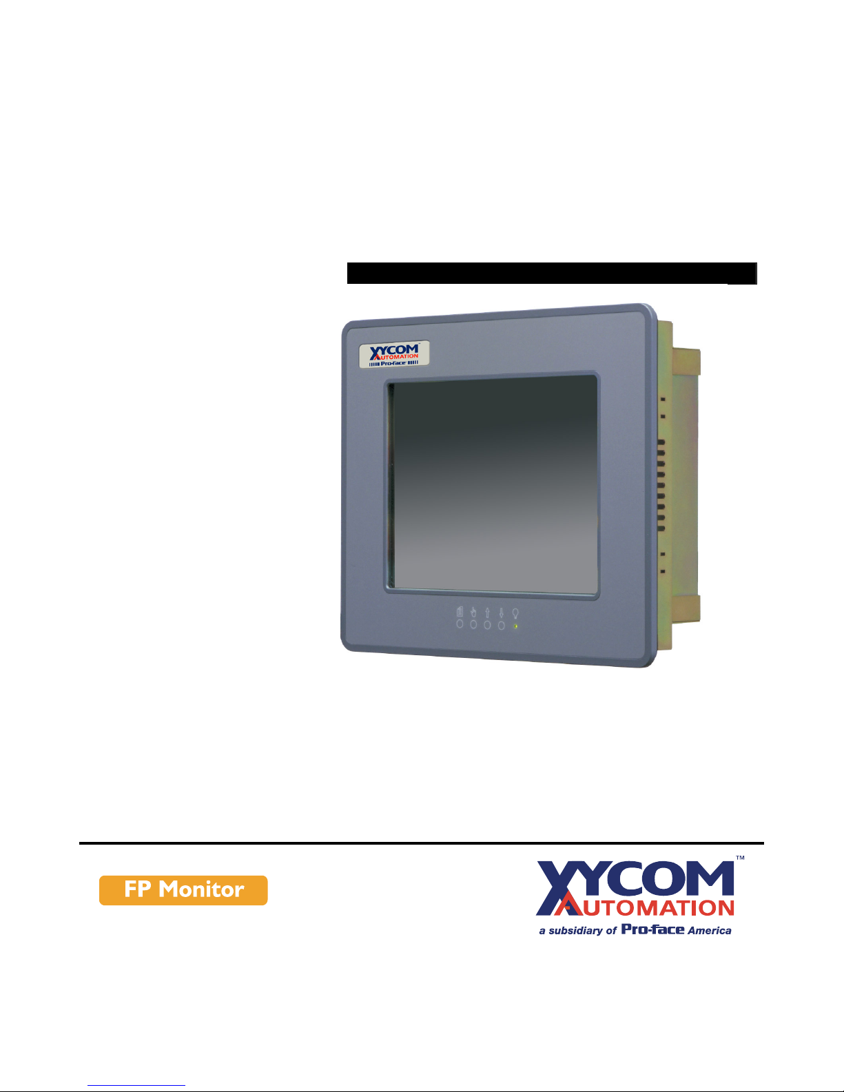
VT1040
FLAT PANEL INDUSTRIAL MONITOR
INDUSTR
Hardware Guide
Page 2

Revision
A
B
C
D
E
Description
Manual released
Preliminary revision released for new controller board
Revised to match other monitor manuals
Manual updated
TIR Caution and driver installation instructions added
Date
12/01
03/02
03/02
06/02
07/04
Xycom Automation Part Number 301040/141283(E)
Trademark Information
Xycom Automation is a trademark of Xycom Automation, Inc. Brand or product names may be
registered trademarks of their respective owners. Windows is a registered trademark of
Microsoft Corporation in the United States and other countries.
Copyright Information
This document is copyrighted by Xycom Automation Incorporated (Xycom Automation) and shall
not be reproduced or copied without expressed written authorization from Xycom Automation.
The information contained within this document is subject to change without notice. Xycom
Automation does not guarantee the accuracy of the information.
United States FCC Part 15, Subpart B, Class A EMI Compliance Statement:
NOTE: This equipment has been tested and found to comply with the limits for a Class A digital
device, pursuant to part 15 of the FCC Rules. These limits are designed to provide reasonable
protection against harmful interference when the equipment is operated in a commercial
environment. This equipment generates, uses, and can radiate radio frequency energy and, if
not installed and used in accordance with the instruction manual, may cause harmful
interference to radio communications. Operation of this equipment in a residential area is likely
to cause harmful interference in which case the user will be required to correct the interference
at his own expense.
For European Users: WARNING
This is a Class A product. In a domestic environment this product may cause radio interference
in which case the user may be required to take adequate measures.
INSTALLATION: Electromagnetic Compatibility WARNING
The connection of non-shielded equipment interface cables to this equipment will invalidate
FCC EMI and European Union EMC compliance and may result in electromagnetic interference
and/or susceptibility levels which are in violation of regulations which apply to the legal
operation of this device. It is the responsibility of the system integrator and/or user to apply the
following directions which relate to installation and configuration:
All interface cables must include shielded cables. Braid/foil type shields are recommended.
Communication cable connectors must be metal, ideally zinc die-cast backshell types, and
provide 360 degree protection about the interface wires. The cable shield braid must be
terminated directly to the metal connector shell, ground drain wires alone are not adequate.
Protective measures for power and interface cables as described within this manual must be
applied. Do not leave cables connected to unused interfaces or disconnected at one end.
Changes or modifications to this device not expressly approved by the manufacturer could void
the user's authority to operate the equipment.
Page 3

Table of Contents
1. Product Overview.................................................................................................... 1
Product Features……………………...…………………………………………………………1
Standard VT1040 Features…………………………………………………………………….1
Parts List……………………………...…………………………………………………………1
Standard VT1040 Parts List…………………………………………………………………...1
Manual Overview………………………………………………………………………………..2
Text Conventions Used in this Manual ...………………………………………………………2
Product Dimensions …………………………………………………………………………….3
Front Panel Controls …………………………………………….……………………………3
Product Specifications and Ratings……..………………………………………………………4
Environmental…………………………………………………………………………………4
Electrical ……………………………………………………………………………………...4
Front Panel/Enclosure .......…….…..……………………….…………………………………..4
Regulatory Compliance ...………………………………...…………………………………..4
Safety Agency Approvals ………………….…………………………………………………4
2. Installation ............................................................................................................... 5
Environmental Considerations …………….……………………………………………………5
System Power …………………………………………………………………………………5
Excessive Heat …………………………..……………………………………………………5
Electrical Noise ...………………………..……………………………………………………6
Line Voltage Variation …………………..……………………………………………………6
Location and Enclosure ………………….……………………………………………………6
Panel Installation …………...……………..……………………………………………………6
Panel Mounting Dimensions ...…………..……………………………………………………7
3. Monitor Settings ......................…..............................................................................8
Mode and Image Adjustment ……………...……………………………………………………8
Video Modes Supported ………………………………………………………………………8
Onscreen Display (OSD) Functions ………....…………………………………………………9
Front Panel Controls ……….…………………………………………………………………9
Main OSD menu …………...…………………………………………………………………9
Color Submenu …………….…………………………………………………………………9
RGB Submenu ……………………………………………………………………………10
Position Submenu ………….…………………………………………………………………10
Image Submenu ………………………………………………………………………………10
Miscellaneous Submenu …...…………………………………………………………………10
OSD Position Submenu……...……………………………………………………………10
Installing the Touch Screen Driver ………………………………………………………11
4. Hardware.................………….....................................................................................12
VGA Input Connector Pin Out ………………………………………………………………….12
Back Light Replacement Procedure …………………………………………………………….12
Appendix A: Reaching Technical Support……………………………………………………...14
i 141283 (E)
Page 4

1. Product Overview
Xycom Automation industrial monitors meet the rigorous requirements of the plant floor
with high-resolution flat panel displays in a rugged housing with an optional resistive
membrane touchscreen. The VT1040 flat panel monitor delivers crisp, bright text and
graphics with a low current draw, and it fits into panels that CRTs cannot.
The VT1040 is self-contained, requiring only to be panel mounted in an appropriate
enclosure and connected to 120/240 VAC and VGA source.
Product Features
Parts List
Standard VT1040 Parts List
Standard VT1040 Features
• 10.4" bright (300 Nit), easy-to-read, high contrast (300:1), color (18 bit/262,144 colors) TFT
flat panel display with VGA (640x480) resolution
• Large viewing area and viewing angles (120° horizontal, 100° vertical)
• Operator input through an optional integrated high-performance (35 million touch)
touchscreen
• Front panel controls with onscreen menus (lock switch on rear of units)
• Long-lasting (50,000 hour) backlight
• Hinged design for easy backlight field replacement
• Simple mounting
• Shallow mounting depth
• Up to 50 foot cables
• Optional 19" EIA rackmount adapter plate
• NEMA 4/12 front panel, when properly mounted
• UL and cUL recognized, CE marked
•
Units ship with all necessary cables and software
When you remove the VT1040 from its shipping carton, verify that you have the parts
listed below. Save the box and inner wrapping in case you need to reship the unit.
• VT1040 unit.
• Ten-foot VGA cable.
• Ten-foot serial cable (touchscreen units only).
• Documentation and Support Library CD-ROM. In addition to containing this manual,
this CD contains all drivers required by this unit (touchscreen drivers in the case of
VT1040T units).
1 141283 (E)
Page 5

Manual Overview
The manual is divided in the following chapters:
• Chapter 1 – Product Overview
• Chapter 2 – Installation
• Chapter 3 – Monitor Settings
•
Chapter 4 – Hardware
Text Conventions Used in this Manual
Throughout this manual, certain terms are formatted in ways that indicate what type of
object is being described. Some information is also segregated to draw attention quickly.
Titles, labels, and messages are indicated by italic text. Computer filenames and text to
be entered by the user will appear in a monospace font. Operator interfaces (such as the
Start menu button) and keyboard keys (such as Enter) appear in a narrow bold typeface.
Other text (such as the word Note) is bold to emphasize it and draw your attention to it.
Some text is segregated into Note, Caution, or Warning boxes. Notes contain extra
information that may make the nearby text, especially the text just before the note, more
understandable. Cautions contain information necessary to prevent damage to the
hardware. Warnings contain information necessary to safeguard the operator.
2 141283 (E)
Page 6
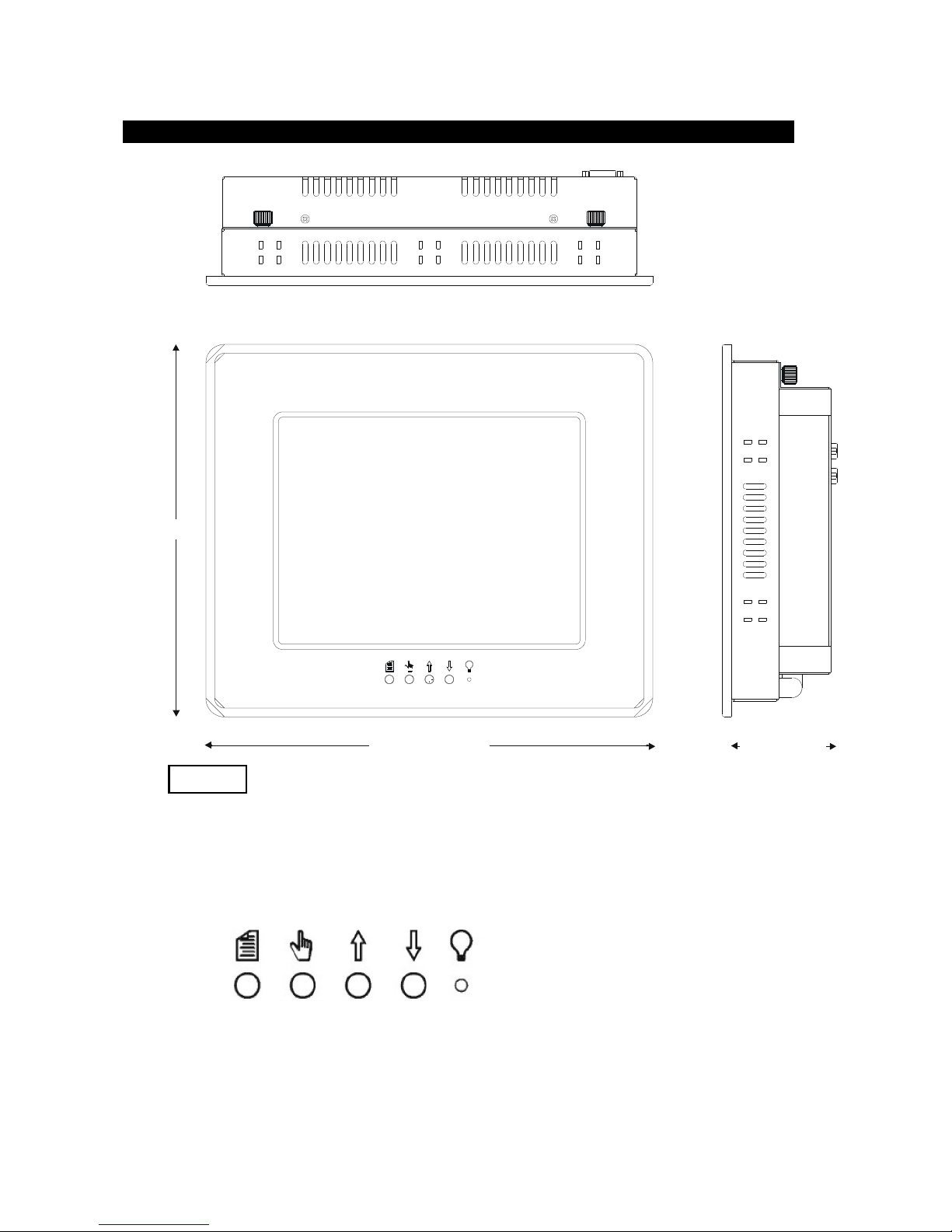
12.60[320.04]
3.00[76.20]
Product Dimensions
10.50[266.70]
1-2
in.[mm]
Front Panel Controls
The front panel controls, from left to right are Menu, Select, Increment, Decrement.
Their use is detailed in Chapter 3— Monitor Settings.
3 141283 (E)
Page 7
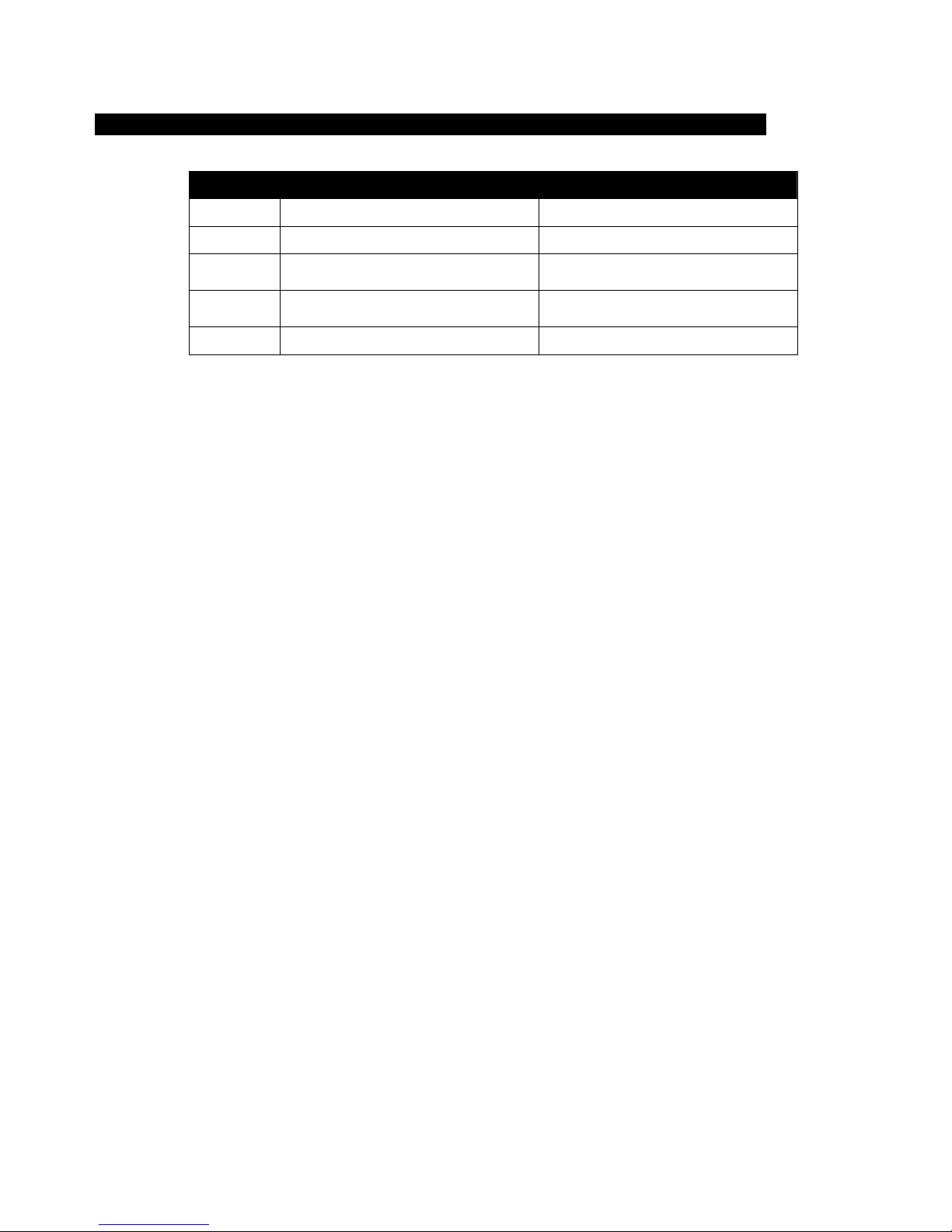
Product Specifications and Ratings
Environmental
Operating Nonoperating
Thermal
Humidity
Shock
Vibration,
5-2000 Hz
Altitude
0°C to 50°C (32°F to 122°F)
20% to 80% RH, noncondensing 20% to 80% RH, noncondensing
15 g peak acceleration,
11 msec duration
0.006" peak-to-peak displacement
1.0 g maximum acceleration
Sea level to 10,000 ft. (3,000 m) Sea level to 40,000 ft. (12,000 m)
Electrical
DC power: 24 VDC, 1 A
AC power: 100-240 VAC, 1.0 A, 60 Hz
Front Panel/Enclosure
NEMA 4/12
Regulatory Compliance
CE
• EN 55022: Class A
• EN 50082-2
-20°C to 60°C (32°F to 122°F)
30 g peak acceleration,
11 msec duration
0.015" peak-to-peak displacement
2.5 g maximum acceleration
• EN 60950
FCC
• 47 CFR, Part 15, Class A
Safety Agency Approvals
UL
• UL 60950
CUL
•
CSA-C22.2, #950
4 141283 (E)
Page 8

2. Installation
Environmental Considerations
The rugged design of the VT1040 allows it to be installed in most industrial
environments. Refer to the electrical and environmental specifications and tolerances
(pg. 4) for more detailed information.
System Power
It is a good practice to use isolation transformers on the incoming AC power line to the
system. An isolation transformer is especially desirable in cases in which heavy
equipment is likely to introduce noise onto the AC line. The isolation transformer can
also serve as a step-down transformer to reduce the incoming line voltage to a desired
level. The transformer should have a sufficient power rating (units of volt-amperes) to
supply the load adequately.
Proper grounding is essential to all safe electrical installations. Refer to the relevant
federal, state/provincial, and local electric codes, which provide data such as the size and
types of conductors, color codes and connections necessary for safe grounding of
electrical components. The code specifies that a grounding path must be permanent (no
solder), continuous, and able to safely conduct the ground-fault current in the system with
minimal impedance (minimum wire required is 18 AWG, 1 mm).
Observe the following practices:
• Separate the power and ground (P. E., or Protective Earth) cable from signal cables at
the point of entry to the enclosure. To minimize the ground wire length within the
enclosure, locate the ground reference point near the point of entry for the plant
power supply.
• All electrical racks or chassis and machine elements should be Earth Grounded in
installations where high levels of electrical noise can be expected. The rack/chassis
should be grounded with a ground rod or attached to a nearby Earth structure such as
a steel support beam. Connect each different apparatus to a single Earth Ground point
in a "star" configuration with low impedance cable. Scrape away paint and other
nonconductive material from the area where a chassis makes contact with the
enclosure. In addition to the ground connection made through the mounting bolt or
stud, use a one-inch metal braid or size #8 AWG wire to connect between each
chassis and the enclosure at the mounting bolt or stud.
Excessive Heat
To keep the temperature in range, the cooling air at the base of the system must not
exceed the maximum temperature specification (see pg. 4). Allocate proper spacing
between internal components installed in the enclosure.
When the air temperature is higher than the specified maximum in the enclosure (see
pg. 4), use a fan or air conditioner to lower the temperature.
5 141283 (E)
Page 9

Electrical Noise
Electrical noise is seldom responsible for damaging components, unless extremely high
energy or high voltage levels are present. However, noise can cause temporary
malfunctions that can result in hazardous machine operation in certain applications. Noise
may be present only at certain times, may appear at widely spread intervals, or in some
cases may exist continuously.
Noise commonly enters through input, output, and power supply lines and may also be
coupled through the capacitance between these lines and the noise signal carrier lines.
This usually results from the presence of high voltage or long, close-spaced conductors.
When control lines are closely spaced with lines carrying large currents, the coupling of
magnetic fields can also occur. Use shielded cables to help minimize noise. Potential
noise generators include switching components, relays, solenoids, motors, and motor
starters.
Refer to the relevant Federal, State/Provincial, and local electric codes, which provide
data such as the size and types of conductors, color codes and connections necessary for
safe grounding of electrical components. It is recommended that high- and low-voltage
cabling be separated and dressed apart. In particular, AC cables and switch wiring should
not be in the same conduit with all communication cables.
Line Voltage Variation
The power supply section of the unit is built to sustain the specified line fluctuations and
still allow the system to function in its operating margin. As long as the incoming voltage
is adequate, the power supply provides all the logic voltages necessary to support the
monitor unit.
Unusual AC line variations may cause undesirable system shutdowns. As a first step to
reduce line variations, correct any possible feed problems in the distribution system. If
this correction does not solve the problem, use a constant voltage transformer. The
constant voltage transformer stabilizes the input voltage to the systems by compensating
for voltage changes at the primary in order to maintain a steady voltage at the secondary.
When using a constant voltage transformer, check that the power rating is sufficient to
supply the unit.
Location and Enclosure
• Place the unit to allow easy access to the system ports.
• Account for the unit dimensions when selecting an installation location or enclosure
(see pg. 3).
• You can maintain the NEMA 4 seal by mounting the unit in an approved enclosure
that has a 14 gauge (0.075"/1.9 mm thick) steel or (0.125"/3.2 mm thick) aluminum
front face.
• Place the unit at a comfortable working level.
• Mount the unit in an upright position, if possible.
• Consider locations of accessories such as AC power outlets and lighting (interior
lighting and windows) for installation and maintenance convenience.
• Prevent condensation by installing a thermostat-controlled heater or air conditioner.
• Avoid obstructing the airflow to allow for maximum cooling.
• Place any fans or blowers close to the heat-generating devices. If using a fan, make
sure that outside air is not brought inside the enclosure unless a fabric or other
6 141283 (E)
Page 10
reliable filter is used. This filtration prevents conductive particles or other harmful
contaminants from entering the enclosure.
• Do not select a location near equipment that generates excessive electromagnetic
interference (EMI) or radio frequency interface (RFI) (equipment such as high-power
welding machines, induction heating equipment, and large motor starters).
• Do not place incoming power line devices (such as isolation or constant voltage
transformers, local power disconnects, and surge suppressers) near the system. The
proper location of incoming line devices keeps power wire runs as short as possible
and minimizes electrical noise transmitted to the unit.
• Make sure the location does not exceed the unit's shock, vibration, and temperature
specifications (see pg. 4 for specifications).
• Install the unit so it does not cause a hazard from uneven mechanical loading.
• Incorporate a readily accessible disconnect device in the fixed wiring on permanently
connected equipment.
•
Avoid overloading the supply circuit.
Panel Installation
This monitor should be mounted in and used where NEMA 4 and NEMA 12 type
enclosures are employed. When mounted properly, the monitor meets or exceeds the
sealing requirements set forth in the NEMA 4 and NEMA 12 specifications. The monitor
uses "U"-shaped clips and a special gasket to achieve the proper seal.
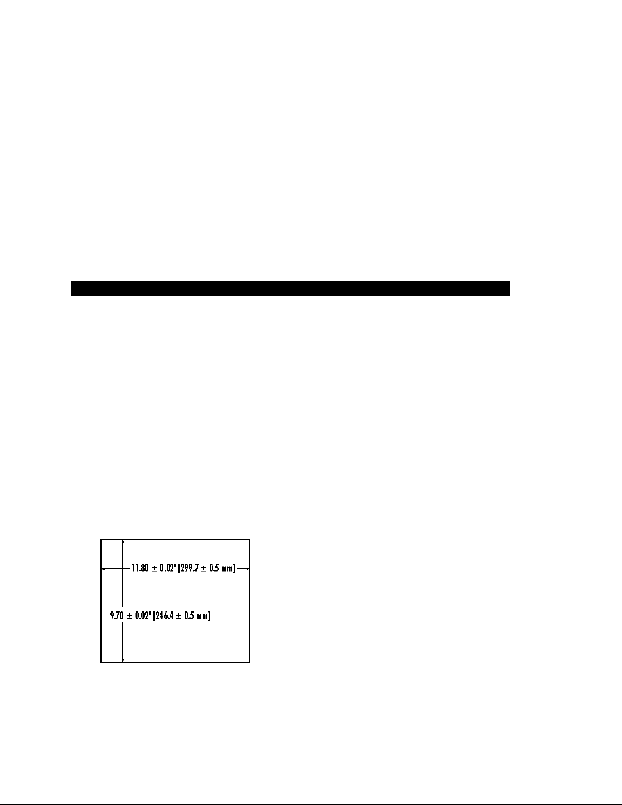
To install the monitor, make a cutout per the diagram below in one of the walls of your
NEMA enclosure. Enclosures made of heavier gauge metal work better in that they won't
deform or bend as easily when the monitor's sealing gasket is compressed. Next hold the
monitor in place while you install the mounting clips. Tighten the clips in a cross pattern.
This will help to develop an even pressure on the sealing gasket. Tighten the clips to the
point were the back of the monitor's front bezel just begins to contact the front of the
NEMA enclosure.
Caution: Do not over tighten, because overtightening can cause damage to the monitor
which can result in loss of seal integrity.
Panel Mounting Dimensions
2-3
7 141283 (E)
Page 11
3. Monitor Settings
Caution
!"""#
Mode and Image Adjustment
Not all video controllers produce exactly the same video output levels or the same timing.
The VT1040 uses onscreen programming to make setup and adjustment easy. The menus
are selected and the menu items are adjusted using the buttons located on the monitor
front panel. These buttons are enabled or disabled by a rocker switch labeled SET UP
located on the side of the monitor. This feature is provided to inhibit tampering once the
monitor is in actual use. Turn the SET UP switch to the On position to enable set up and
adjustment. Prior to adjusting your monitor you should initialize the display settings in
the Windows control panel to the following choices:
Colors: 256
Vertical Refresh: 60 Hz
Resolution: 640 x 480
Monitor Type: “Viewsonic 15”
Note: The monitor type option is not available in Windows NT.
Once the monitor is powered up, you can access the onscreen display (OSD) functions by
pressing the menu button. After the menu appears, select the Auto Setup function
following the directions given below. The monitor will automatically adjust to the
incoming video signal. Then select the Image | Auto phase function or manually fine-tune
the image. Finally, set the brightness and contrast settings to your individual preference.
Video Modes Supported
Mode Horizontal Sync
Rate (KHz)
VGA (640x480)
VGA (720x400)
Mac (1152x870)
VESA (640x480)
31.47
31.47
68.68
37.86
37.50
Vertical Sync
Rate (KHz)
59.94
70.10
75.06
72.81
75.00
Dot Frequency
(MHz)
25.18
28.32
100.0
31.5
31.5
8 141283 (E)
Page 12
Onscreen Display (OSD) Functions
Front Panel Controls
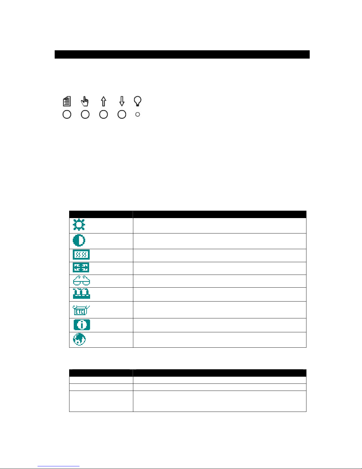
The front panel controls, from left to right are Menu, Select, Increment, Decrement and
Power.
Menu: This button opens and closes menu screens. This button will perform the menu
command labeled number one.
Select: This button selects the highlighted menu item. This button will perform the menu
command labeled number two.
Increment and Decrement: These buttons are used to scroll through menu items or to
adjust settings.
Power: Power on LED.
Main OSD menu
This menu is opened with the Menu button. The following icons are displayed with their
labels appearing in the top blue bar of the menu screen.
Menu Item Description
Brightness Increase/decrease panel brightness level:
Brightness
Contrast
Color
Position
Image
Autosetup
Miscellaneous
System Info
Language
Press Increment or Decrement to adjust; range is 0 to 63.
Increase/decrease panel contrast level:
Press Increment or Decrement to adjust; range is 0 to 200.
Opens the Color submenu (see below).
Opens the Position submenu (see below).
Opens the Image submenu (see below).
Automatically adjusts monitor (position, image size, tuning etc.)
Press Increment or Decrement to select Yes or No.
Opens the Miscellaneous submenu (see below).
Displays system information.
Select OSD language:
Press Increment or Decrement to choose English or French.
Color Submenu
Menu Option Description
Auto Balance Automatic RGB calibration.
RGB Opens the RGB submenu (see below).
Color Temperature Adjust the color temperature:
Press Increment or Decrement to adjust; the choices are
5000K, 6000K, 7000K, 8000K, 9000K, 10000K.
9 141283 (E)
Page 13
RGB Submenu
Menu Option Description
Red Increase/decrease red color level:
Green Increase/decrease green color level:
Blue Increase/decrease blue color level:
Position Submenu
Menu Option Description
Image Horizontal Position Move the image position horizontally:
Image Vertical Position Move the image position vertically:
Auto Center Set the screen to center:
Image Submenu
Menu Option Description
Phase Adjust the phase on the screen:
Horizontal size Adjust the image size:
Auto phase Set the screen to center:
Miscellaneous Submenu
Menu Option Description
Load Default Load the default settings stored in nonvolatile memory.
OSD Timeout Set the menu timeout period:
OSD Position Select Horizontal Position or Vertical Position in the OSD
OSD Position Submenu
Menu Option Description
Horizontal Position Adjust the display horizontal position:
Vertical Position Adjust the display vertical position:
Press Increment or Decrement to adjust; range is 0 to 127.
Press Increment or Decrement to adjust; range is 0 to 127.
Press Increment or Decrement to adjust; range is 0 to 127.
Press Increment or Decrement to adjust; range is 6 to 301.
Press Increment or Decrement to adjust; range is 1 to 36.
Press Increment or Decrement to select Yes or No.
Press Increment or Decrement to adjust; range is 0 to 61.
Press Increment or Decrement to adjust; range is 800 to 880.
Press Increment or Decrement to select Yes or No.
Press Increment or Decrement to adjust; the choices are 15
seconds, 30 seconds, 45 seconds, 60 seconds.
Position submenu:
Press Increment or Decrement to select Yes or No.
Press Increment or Decrement to adjust; range is 0 to 98.
Press Increment or Decrement to adjust; range is 1 to 89.
10 141283 (E)
Page 14

Installing the Touch Screen Driver
If your Xycom flat panel monitor has the touch screen option, you will have to load the correct
touch screen driver on the computer to which you will be connecting the monitor. The
following steps should be performed on that computer.
Note: The following instructions assume that a web browser is installed on the
1. Insert the Xycom Automation Documentation and Support Library CD into the CD-ROM
drive.
2. If the Doc CD autostarts, proceed to the next step. If the Doc CD does not autostart, open
the CD in Windows Explorer and double click on the file “index.html.”
3. Choose “Flat Panel Monitors” from the links at the top of the home page and then choose
the appropriate monitor model on the next page. From the resulting page, you can
download the User Manual and/or the touch screen driver.
4. Click on the link to “elo.zip” (the drivers for all of the operating systems are in this file).
Type a destination folder to save the file in and press the “Save” button. The download will
be very short.
5. Using Windows Explorer, go to the downloaded file and extract the compressed files into a
folder of your choosing.
6.
Go to the folder “Elo\Serial Controller” and then to the folder for your operating system.
computer.
• If you are installing the DOS driver, click on “install.exe” and follow the
instructions.
• If you are installing one of the Windows drivers, click on “setup.exe” and follow
the instructions.
If your computer doesn’t have a web browser, open the CD in Windows Explorer and choose
the “ELO.zip” file from the folder:
DRIVERS/Touchscreen
Copy it to a folder on your computer and follow steps 5 & 6 above.
11 141283 (E)
Page 15
4. Hardware
VGA Input Connector Pin Out
Signal Name
Red
Green
Blue
GND-Digital
GND-Red return
GND-Green return
GND-Blue return
GND-Digital
Hsync
Vsync
Back Light Replacement Procedure
After 50,000 hours of use, the two lamps used for LCD back lighting may become dim or
burn out. You may return the monitor to Xycom for lamp replacement or you can order
new lamps and follow the procedure below to install them. You can perform the lamp
replacement procedure without removing the monitor from the NEMA enclosure where it
is mounted, but you should do this only in a clean environment. Otherwise, the procedure
is better performed at a service bench.
1.
TURN THE MONITOR POWER OFF AND DISCONNECT THE LINE CORD
15-pin D-Shell (Female)
10
11
12
13
14
15
1
2
3
4
5
6
7
8
9
2.
Loosen the four thumbscrews that hold the back of the monitor on.
3.
Separate the two halves of the monitor. If the unit is equipped with a touchscreen,
you will have to disconnect its cable.
4.
The lamps are mounted in small plastic carriers that slide in the right side of the LCD
display at the top and bottom edges.
5.
Note their orientation and then unplug the two sets of lamp wires (3" pink and white
silicone wires) from the nearby inverter.
6.
Look in the hole where the lamp is presently installed and note the small black
locking tab on the front side of each hole. With a small slotted screwdriver, depress
the tab while carefully pulling on the wires and slide the lamps outward. Discard the
old lamps.
7.
Carefully slide the new lamps fully into place noting the top lamp has a small triangle
molded in the end where the wires protrude. Similar triangles a stamped in the LCD
sheet metal near the top hole.
12 141283 (E)
Page 16

8.
Reconnect the lamp wires to the inverter. These are keyed connectors permitting
insertion in only one orientation.
9.
You may now want to clean the LCD and the inside of the monitor window or
touchscreen with a slightly damp soft cloth.
10.
Carefully reunite the two monitor halves remembering to reconnect the touchscreen
cable if the unit is so equipped.
11.
The lamp replacement procedure is now complete.
13 141283 (E)
Page 17

Appendix A – Technical Support
Reaching Technical Support
Xycom Automation Technical Support offers a variety of support options to answer any
questions on Xycom Automation products and their implementation.
Refer to the relevant chapter(s) in your documentation for a possible solution to any
problem you may have with your system. If you find it necessary to contact Technical
Support for assistance, please have the following information at your fingertips:
1. Serial number and model number.
2. The operating system type and version (i.e., Microsoft Windows NT version 4.0).
3. Exact wording of system error messages encountered.
4. Any relevant output listing from the Microsoft Diagnostic utility (MSD) or other
diagnostic applications.
5. Details of attempts made to rectify the problem(s) and results.
6. The log number assigned from Xycom Automation Technical Support if this is an
ongoing problem.
7. The name of the Technical Support Engineer with whom you last spoke, if known.
Internet Access
Xycom Automation provides both World Wide Web and e-mail access via the Internet.
To access the Xycom Automation Home Page, use http://www.xycom.com. This page
contains the newest product datasheets, references by industrial sector, and application
notes.
Email
To reach Xycom Automation Technical Support via email: [email protected]
Phone
You can reach Xycom Automation Technical Support via phone: 734/944-0482
Fax
You can fax your questions to Xycom Automation Technical Support at: 734/429-1010
14 141283 (E)
Page 18

Xycom Automation, Inc.
750 North Maple Drive
Saline, MI 48176
141283(E)
734-429-4971 •••• Fax: 734-429-1010
http://www.xycom.com
 Loading...