

Page 1

9457
Industrial PC/AT™
Computer System
P/N 110355-001B
1997 XYCOM, INC.
Printed in the United States of America
Part Number 110355-001B
XYCOM
750 North Maple Road
Saline, Michigan 48176-1292
(313) 429-4971
Page 2

Xycom Revision Record
Revision Description Date
A Manual Released 7/96
B Manual Updated 6/97
Trademark Information
Brand or product names are registered trademarks of their respective owners.
Windows is a registered trademark of Microsoft Corp. in the United States and other countries.
Copyright Information
This document is copyrighted by Xycom Incorporated (Xycom) and shall not be reproduced or copied without
expressed written authorization from Xycom.
The information contained within this document is subject to change without notice. Xycom does not
guarantee the accuracy of the information and makes no commitment toward keeping it up to date.
Address comments concerning this
manual to:
xycom
Technical Publications Department
750 North Maple Road
Part Number: 110355-001B Saline, Michigan 48176-1292
Page 3

Table of Contents
Chapter 1 – Introduction
Product Overview ........................................................................................................1-1
About This Manual......................................................................................................1-3
Unpacking the System................................................................................................1-3
System Components...................................................................................................1-4
Computer Module.....................................................................................................1-4
Monitor Module ........................................................................................................1-6
Quick Start-Up.......................................................................................................... 1-10
Regulatory Compliance.............................................................................................. 1-12
Chapter 2 – Testing
Checking System Setup ..............................................................................................2-1
Initiating the Tests.......................................................................................................2-1
Preparing for the Tests ................................................................................................2-2
Running the Tests .......................................................................................................2-2
Chapter 3 – Installation
System Components...................................................................................................3-1
Preparing the System for Use......................................................................................3-4
Installing Internal Hardware Options ..............................................................................3-4
Installation and Removal of the CPU Board .................................................................3-4
Installing PC Boards .................................................................................................3-6
Installing the Front Floppy Kit....................................................................................3-6
Installing a Device in the 5.25" Drive Bay ....................................................................3-9
Installing External Hardware Options ........................................................................... 3-11
Installing the Remote Mount Kit............................................................................... 3-11
Installing Keyboard Cable Clamps............................................................................ 3-13
Installing Operating Systems ..................................................................................... 3-14
Installing Drivers ........................................................................................................ 3-14
Video Drivers .......................................................................................................... 3-15
Mouse Drivers ........................................................................................................ 3-15
Touch Screen Drivers.............................................................................................. 3-15
CD-ROM Drivers..................................................................................................... 3-16
Miscellaneous Drivers ............................................................................................. 3-16
General Installation and Mounting Considerations ........................................................ 3-16
System Power ....................................................................................................... 3-17
Excessive Heat ...................................................................................................... 3-18
Excessive Noise..................................................................................................... 3-18
Excessive Line Voltage ........................................................................................... 3-18
Installing the System into a Panel .............................................................................. 3-19
Mounting the Computer Module to the Monitor Module ................................................. 3-21
Removing the Computer Module................................................................................. 3-22
Derating the Power Supply......................................................................................... 3-23
i
Page 4

9457 Industrial Computer
Chapter 4 – System Operation
Using the Keypads ......................................................................................................4-1
Using the Built-in Mouse..............................................................................................4-1
System Status LEDs ..................................................................................................4-2
Adjusting the Monitor ..................................................................................................4-3
On-Screen Display Mode Options .................................................................................4-3
Power Management Modes ..........................................................................................4-5
Degaussing the Monitor ...............................................................................................4-6
Chapter 5– Programmable Keypad Utility Program
Loading the Programmable Keypad Utility.....................................................................5-1
Using the Programmable Keypad Utility........................................................................5-1
Startup....................................................................................................................5-2
Utility Batch Mode ....................................................................................................5-2
Main Menu.................................................................................................................5-3
Exit .........................................................................................................................5-3
Files Menu...............................................................................................................5-3
Macros Menu ...........................................................................................................5-4
Upload Menu............................................................................................................5-8
Download Menu........................................................................................................5-8
Utilities Menu ...........................................................................................................5-9
Codes...................................................................................................................... 5-10
Chapter 6 – Maintenance
Preventive Maintenance ...............................................................................................6-1
Care of the 9457 Cabinet...........................................................................................6-2
Changing the Fan Filters ...........................................................................................6-2
Chemical Compatibility ................................................................................................6-3
Compatible Lubricants ..............................................................................................6-5
Compatible Cleaning Agents......................................................................................6-6
Non-compatible Cleaning Agents ...............................................................................6-6
Spare Parts List..........................................................................................................6-7
Product Repair............................................................................................................6-8
Preparing the Unit for Shipment .................................................................................6-8
Appendix A – Specifications
Environmental Specifications ........................................................................................A-1
Hardware Specifications ..............................................................................................A-2
Default Video Modes ...................................................................................................A-3
Appendix B – Pinouts
Keyboard Connectors..................................................................................................B-1
Serial Ports................................................................................................................B-2
Host/LED Port ............................................................................................................B-3
ii
Page 5

Table of Contents
iii
Page 6

United States FCC Part 15, Subpart B, Class A EMI
Compliance Statement
Note: This equipment has been tested and found to comply with limits for a Class A
digital device, pursuant to part 15 of the FCC Rules. These limits are designed to provide
reasonable protection against harmful interference when the equipment is operated in a
commercial environment. This equipment generates, uses, and can radiate radio frequency
energy and, if not installed and used in accordance with the instruction manual, may cause
harmful interference to radio communications. Operation of this equipment in a residential
area is likely to cause harmful interference in which case, the user will be required to correct the interference at his own expense.
For European Users - WARNING
This is a Class A product. In a domestic environment this product may cause radio inte rference in which case the user may be required to take adequate measures.
Installation: Electromagnetic Compatibility Warning
This monitor has been tested to EN 61000-4-8 for immunity to 50 Hz, 3 A/m magnetic
fields. Magnetic fields of this magnitude have the potential to create slight “jitter” on the
display. This jitter is the result of the magnetic field affecting the electron beam, which is
inherent to CRT technology and so cannot be reduced through electrical design. In order
to minimize the potential for this effect, do not install the monitor near devices which can
be expected to create significant magnetic fields. Examples are devices with inductive
coils such as alarm bells, speakers, relays, transformers, motors, or conductors which are
expected to conduct high levels of current. If screen jitter occurs and is due to 60 Hz AC
power, then setting the monitor vertical refresh rate to 60 Hz may correct the problem.
Otherwise, set the vertical refresh rate to the highest possible frequency.
The connection of non-shielded equipment interface cables to this equipment will invali date FCC EMI and European Union EMC compliance and may result in electromagnetic
interference and/or susceptibility levels which are in violation of regulations which apply to
the legal operation of this device. It is the responsibility of the system integrator and/or
user to apply the following directions which relate to installation and configur ation:
1. All interface cables must include shielded cables. Braid/foil type shields are recom-
mended. Communication cable connectors must be metal, ideally zinc die-cast backshell types, and provide 360° protection about the interface wires. The cable shield
braid must be terminated directly to the metal connector shell; ground drain wires
alone are not adequate.
2. Protective measures for power and interface cables as described within this manual
must be applied. Do not leave cables connected to unused interfaces or disconnected
at one end. Changes or modifications to this device not expressly approved by the
manufacturer could void the user’s legal authority to operate the equipment.
Page 7

Page 8

Chapter 1 – Introduction
Product Overview
The 9457 Industrial Computer System puts the power and versatility of an IBM
PC/AT-compatible computer in a package that is ideal for the factory floor and other
harsh environments. The Xycom 9457 Industrial PC/AT Computer System features an
open-architecture to meet a wide variety of applications where both a powerful PC and
durable industrial enclosure are required. The system integrates a computer card cage,
mass storage, display, keypads, and power supply in a truly industrial form factor.
The 9457 system includes a seven-slot passive backplane, a SVGA monitor, hard and
floppy disk drive facilities, and data entry and function keypads. The front panel is
sealed to NEMA 4/4X/12 standards, and the CRT is protected with an impact-resistant
shield. The open-architecture design accepts any IBM PC, XT, AT or PCI-compatible
cards.
The system is shipped with a Pentium
specific configuration of which is determined when the system is ordered. The processor
board combines all the functions of a complete IBM PC/AT compatible computer on a
single, industrially-hardened circuit board.
A complete 9457 computer system consists of two components: a computer module and
a monitor module. This modular design allows easy access to the boards, switches,
power supply and disk drives mounted in the computer module without removing the
monitor module. Once mounted, the computer module is easily removed by loosening
two thumb screws and sliding it out from under the monitor module.
processor-equipped CPU board installed, the
The computer module provides the following standard features:
• A passive backplane featuring four ISA and two PCI slots for user expansion.
• CPU card featuring high-speed Pentium processor technology
• High-capacity IDE hard disk drive
• 3.5-inch, 1.44 Mbyte floppy drive
• MS-DOS installed on the hard disk
• 200-watt power supply
• IBM PC/AT/XT compatibility
• Parallel printer port
• Two RS-232C serial ports
• Integrated PCI video support
1-1
Page 9

9457 Industrial Computer
• One user-configurable rear-accessible 5.25" drive bay (used by CD-ROM drive op-
tion if purchased)
• One user-configurable front-accessible 3.5" drive bay
The monitor module provides the following standard features:
• 17" diagonal SVGA CRT with .28 mm dot pitch
• Variable scan frequencies in the following ranges:
•
•
• 1280 × 1024 maximum resolution (at 60 Hz), non-interlaced
• Digitally-controlled “On-Screen Display” monitor adjustments
• NEMA 4/4X/12 sealed front panel
• Front- and rear-mounted PS/2-compatible keyboard connectors
• Hard drive and serial port activity, power, fault and maintenance LEDs
The monitor module is available in a configuration featuring sealed keypads and a
mouse. This model also includes
45 Hz to 125 Hz vertical scan frequency
15 KHz to 125 KHz horizontal scan frequency
• 30-position sealed function keypad with full alpha capability
• 28-position sealed numeric entry and cursor control keypad
• Alpha lock indicator LED
• Integrated mouse
A configuration featuring an analog touch screen is available, without keypads or an integrated mouse.
Optional items available for use with the 9457 include
• Touch screen (includes Windows 3.1 and Window 95 drivers)
• Windows
®
95 or Windows NT™ operating systems
• Larger hard drives
• Solid state (Flash) drives
• CD-ROM drive
• 4100-KB2 External full-stroke keyboard*
• 8000-KB5 Panel-mount 104-key keyboard*
• 8000-KB7 Stand-alone 104-key QWERTY NEMA 4 sealed keyboard*
•
4100-WIN Microsoft Windows
1-2
9457-RMKRemote mounting kit
•
9457-FFK Front-mount floppy drive kit
•
9457-RF 19" Rack filler panel
•
Page 10

9457-RFC 19" Rack filler panel with cutout for front-mounted floppy drive.
•
*These peripheral devices are not CE compliant.
About this Manual
This manual describes the 9457 Industrial PC/AT computer system. As the 9457 supports a variety of processor and peripheral options, refer to the documentation that accompanied the particular processor board or peripheral for information specific to that
component.
Unpacking the System
The 9457 is shipped in two cartons. One contains the computer module, and the other the
monitor. As you remove each from its shipping carton, verify that you have the parts
listed below. It is a good idea to save the boxes and inner wrapping in case you need to
reship the units.
The 9457 computer module carton contains
Chapter 1 – Introduction
• 9457 computer module
• Documentation kit, which includes
Power cable
•
Diagnostic software disk
•
Processor card manual
•
Display drivers disk
•
9457 user manual
•
Business reply card
•
If you ordered operating system software, you will receive operating system disks and
manuals.
The monitor module carton should contain
• 9457 monitor module
• 3-foot (914.4 mm) monitor power cable
• 18-inch (457.2 mm) video cable
• 24-inch (609.6 mm) Host/LED cable
• 2 steel half-clamps
• 14 - #10-32 nuts
• 1 - #6-32 screw
If you ordered the system with a touch screen installed, you will receive
• Touch screen driver disk and manual
1-3
Page 11
9457 Industrial Computer
(2)
Windows NT and OS/2 drivers must be ordered separately
• 18-inch (457.2 mm) touch screen (serial) cable
If you ordered the system with a built-in mouse, you will receive
• Mouse driver disk and manual
• 18-inch (457.2 mm) mouse (serial) cable
If you ordered the system with a CD-ROM installed, you will receive a CD-ROM driver
disk.
System Components
Computer Module
Note
Front
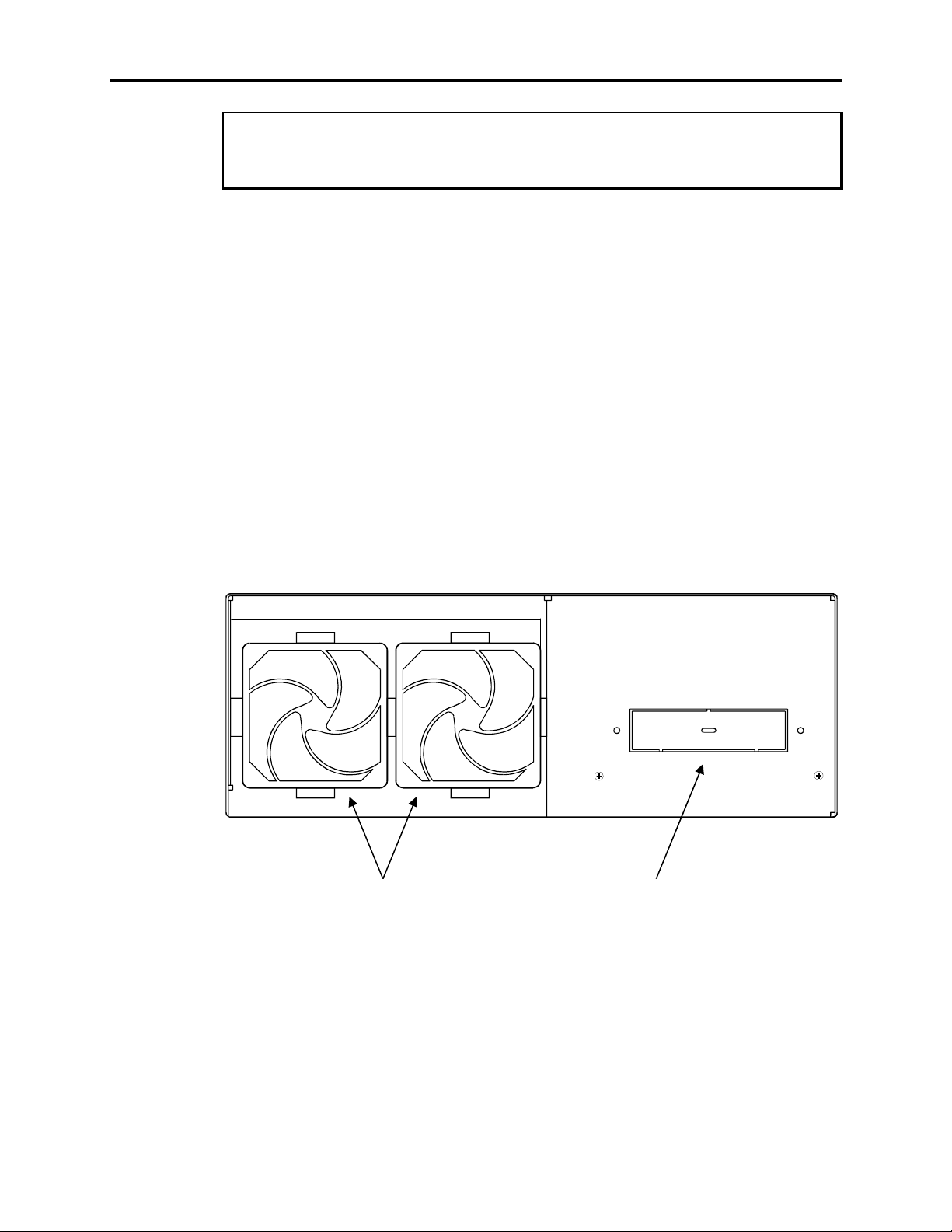
Figure Chapter 1 -1 illustrates the features on the front of the 9457 computer module.
Fan Intake
Filters
Figure Chapter 1 -1. 9457 Computer Module Front Components
Front Drive
Bay
1-4
Page 12
Chapter 1 – Introduction
Fan Intake Filters
These replaceable filters separate particulate contaminants
from the cooling air drawn into the 9457.
Front Drive Bay
This bay may hold a single 3.5" externally-accessible mass
storage device, such as a floppy drive or tape back-up unit.
To install a device in this bay, you must install the 9457-FFK
Front Floppy Kit.
Rear
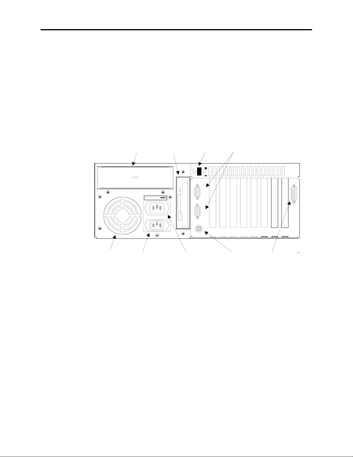
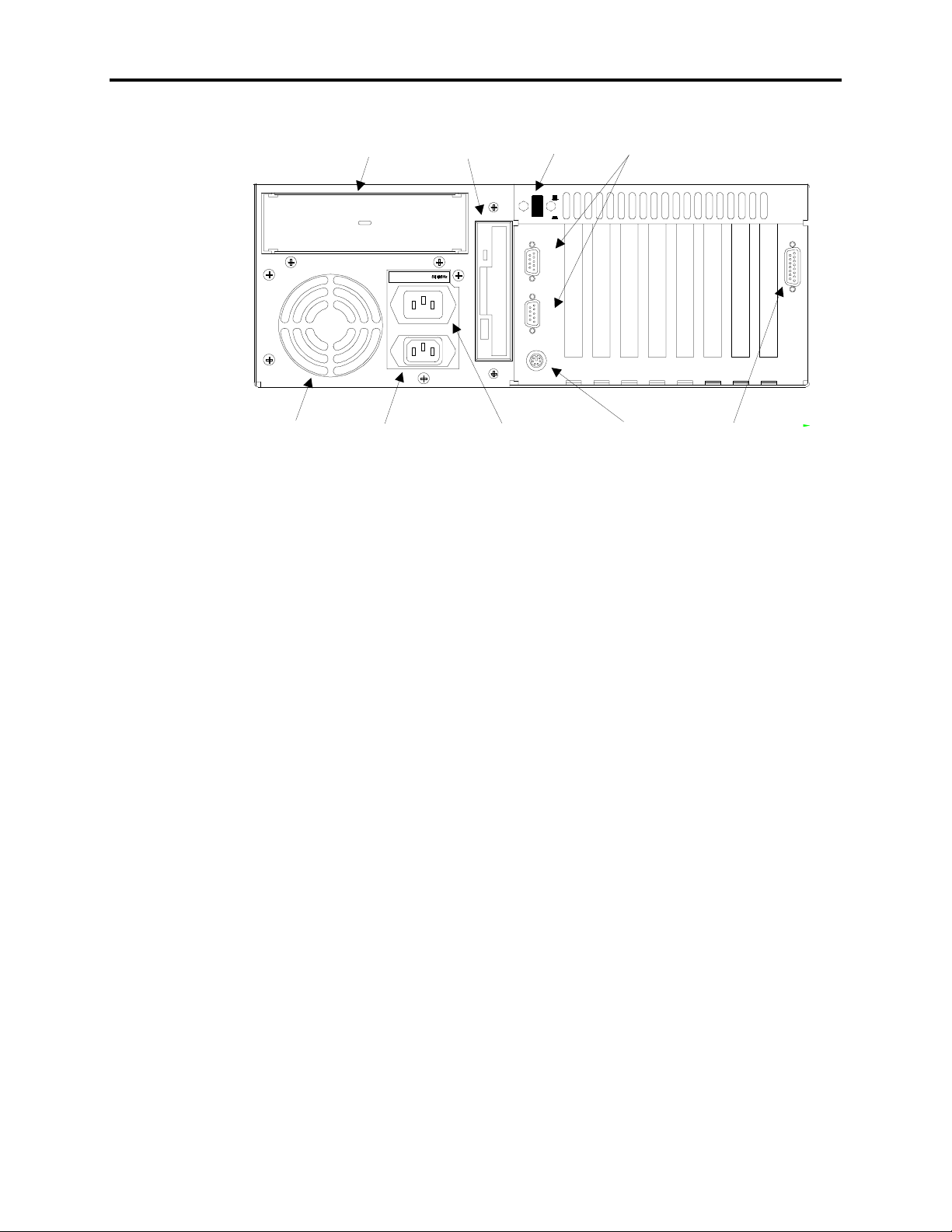
Figure Chapter 1 -2 illustrates the features on the rear of the 9457 computer module.
3.5"
5.25" Bay
(optional CD-ROM)
100-120V ~ 3A MAX .
200-240V ~ 3A MAX .
Floppy
Drive
ON/OFF
Switch
KEYBOARD
Serial
Ports
o
I
C
O
M
1
C
O
M
2
H
O
S
T
L
E
D
/
Cooling
Grille
Receptacle
Figure Chapter 1 -2. 9457 Computer Module Rear Components
ON/OFF Switch
Cooling Grille
Power Receptacle
Monitor Auxiliary
Outlet
Power
Monitor Auxiliary
Outlet
Keyboard
Port
Host/LED
Connector
This switch should be positioned to OFF (O) until the system
is properly configured and connected to a 115 VAC or
230 VAC power source.
Unobstructed airflow is essential to proper ventilation and
cooling of the 9457. Do not obstruct this outlet.
The plug and cord must be securely positioned before turning
power ON.
This switched outlet may only be used to power the 9457
monitor module or a monitor or other device that draws less
than 3.0 A peak current.
1-5
Page 13

9457 Industrial Computer
Serial Ports
Keyboard Port
The serial port connectors are a pair of male DB-9 connectors
located above the keyboard connector. As shipped, these are
configured as COM1 and COM2, in the manner labeled on
the back panel.
This six-pin mini-DIN connector allows a PS/2-compatible
keyboard to be directly connected to the 9457 computer
module.
Use of this port is not recommended. If an external keyboard
is desired, use the External Keyboard port or the Keyboard In
port on the Monitor Module.
Note
Do not connect a keyboard to the keyboard port on the back of the 9457 computer
module if the computer module is connected to the monitor module using the
Host/LED cable.
Only connect a keyboard to this port if the computer and monitor modules are
connected using the Host/LED cable.
Host/LED Connector
Connect the 15-pin Host/LED cable from the 9457 monitor
module to this socket.
not
Monitor Module
Front Panel
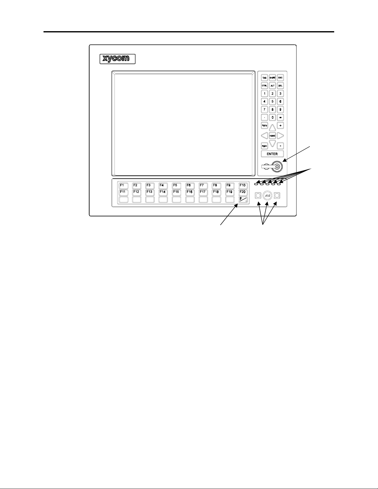
The 9457 monitor module is equipped with a NEMA 4/4X/12 sealed front panel. The
panel protects the system’s interior when the system is properly panel mounted. See
Chapter 3 for panel-mounting instructions. Figure Chapter 1 -3 illustrates the front panel
features of the 9457 monitor module.
1-6
Page 14
B
d
A
KLMN
()
U
C
#
VW X Y Z
*
D
EF
OP
BACK
SPACE
GHI
Q
RS
INS
PAUSE
SPACE
/
:\
J
T
A
Chapter 1 – Introduction
External Keyboar
Port
Status
LEDs
FAULT MAINT POWER DISK COM
Monitor
Function/
Alpha Keys
Data Entry Keypad
External Keyboard
Port
Function/Alpha
Toggle Key
Industrial
Mouse
Figure Chapter 1 -3. 9457 Monitor Module Front Panel
Protected from breakage by an impact-resistant shield, the 17"
monitor supports high-resolution SVGA color modes. If the
touch screen option is installed, the shield is replaced by a
safety glass-backed touch panel.
These 30 keys provide the user with an easy means of entering
text data, and easy access to familiar PC routines. These keys
are located directly below the monitor.
On models ordered without keypads, this panel contains only
the system status LEDs.
This 28-key numeric keypad includes 15 data entry keys; the
up, down, left, and right arrows; and numbers 0-9.
On models ordered without keypads, this panel is blank.
This six-pin mini-DIN connector allows you to connect a
PS/2-compatible keyboard to the 9457 monitor module. For
this feature to function, the Host/LED cable must be connected
between the port on the back of the 9457 monitor module and
the Host/LED port on the back of the 9457 computer module.
1-7
Page 15
9457 Industrial Computer
When not using a keyboard connected to the front keyboard port on the 9457 monitor
module,
keyboard port uncapped defeats the NEMA-compliant seal feature incorporated into
the design of the 9457 monitor module.
always
Caution
keep the keyboard port capped using the attached plug. Leaving the
Left Mouse Key
This key serves the same function as the left button on a conventional mouse.
Mouse Dome
This dome is used to move the mouse pointer around the screen.
Press the edge of the dome that corresponds to the direction in
which you wish to move the pointer.
Right Mouse Key
This key serves the same function as the right button on a conventional mouse.
Status LEDs
Indicate the state of the computer, as described in Chapter 4,
tem Status LEDs
.
Rear
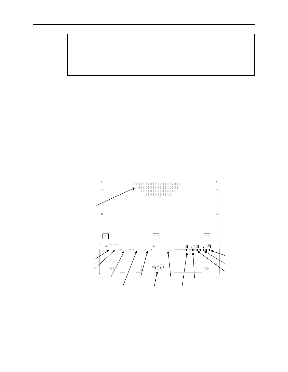
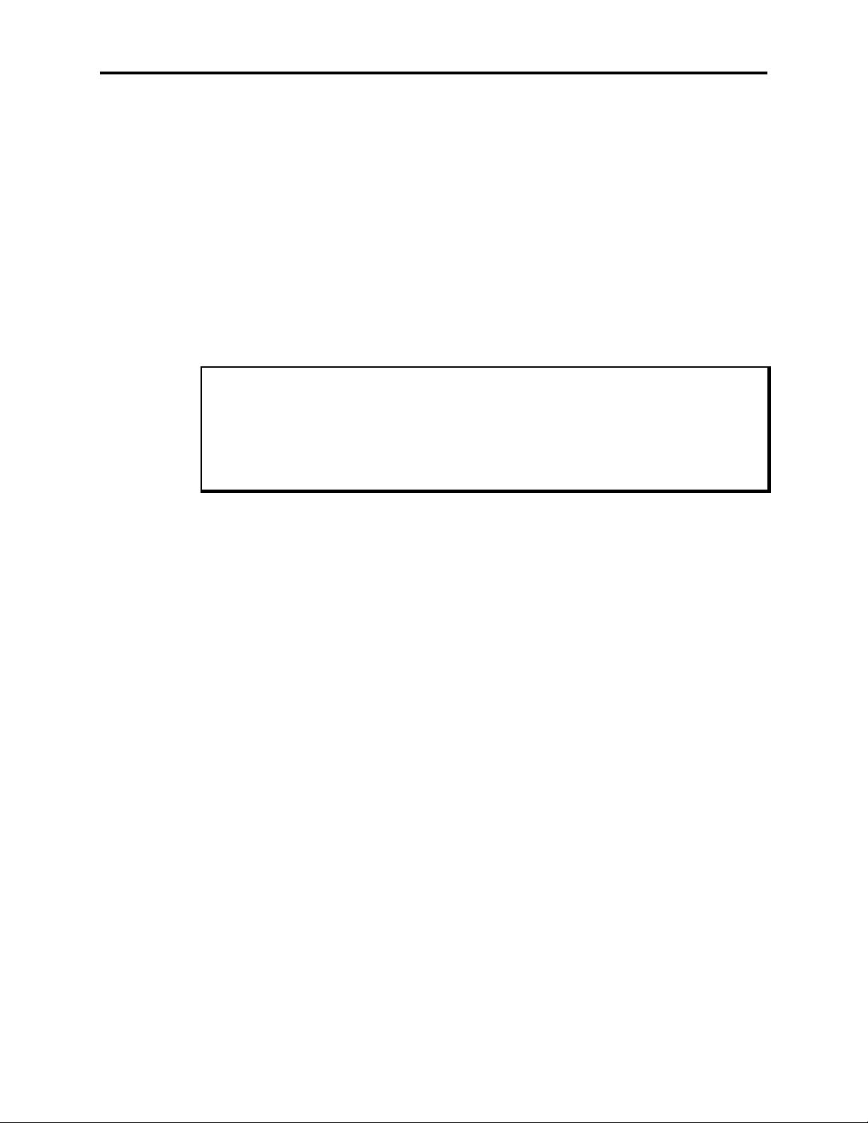
Figure Chapter 1 -4 illustrates the rear components of the 9457 monitor module.
Cooling
Grille
Sys-
1-8
Keyboard
In Port
Keyboard
Out Port
TOUCH
HOST/LED MOUSE VIDEO
SCREEN
Host/LED
Connector
Touch Screen
Port
Mouse
Port
Power
Receptacle
Video Input
Port
Contrast
Knob
Brightness
Knob
Figure Chapter 1 -4. 9457 Monitor Module Rear Components
On-Screen
Display
Button
Soak Test
Button
Degauss
Button
Page 16
Chapter 1 – Introduction
Cooling Grille
Unobstructed airflow is essential to proper ventilation and
cooling of the 9457. Do not obstruct this outlet.
Keyboard In Port
This port provides a location to connect a standard
PS/2-compatible keyboard to the back of the 9457 monitor
module.
Keyboard Out Port
This six-pin mini-DIN connector allows you to connect a
PS/2-compatible keyboard cable between the monitor module
and a computer module.
Use of this port is not recommended, since in normal operation, keyboard signals are transmitted through the Host/LED
connector.
Note
When connecting the monitor module to the computer module, use
Host/LED cable or a cable between the monitor module’s Keyboard Out port and the
computer module’s Keyboard port,
but not both
. Using both cables will cause the key-
board to operate improperly.
Host/LED Connector
Connect the 15-pin Host/LED cable from the 9457 computer
module to this socket. This connector provides the power,
keyboard, and LED signals to the monitor module’s front
panel.
either
the supplied
Touch Screen Port
Mouse Port
Power Receptacle
Video Input Port
If the 9457 monitor module comes equipped with a touch
screen, you must connect a cable between this connector and
either the COM1 or COM2 connector on the 9457 computer
module.
If the 9457 monitor module comes equipped with a built-in
mouse, you must connect a cable between this connector and
either the COM1 or COM2 connector on the 9457 computer
module.
The plug and cord must be securely positioned before turning
power ON.
This 15-pin high-density female connector is used to connect
the 9457 monitor module to the video output of the 9457
computer module.
1-9
Page 17

9457 Industrial Computer
Video Controls
The pinouts for connectors and ports are shown in Appendix B.
The video controls consist of two knobs and five buttons.
These are, from left to right:
Contrast knob – Turning this knob adjusts the contrast on
the display.
Brightness knob – Turning this knob adjusts the brightness
of images on the display.
Degauss button – Used to manually degauss the monitor.
Use of this control is described in Chapter 4.
Soak Test button – This button is not used during normal
operation.
On-Screen Display mode button – This button is used to
select On-Screen Display mode to adjust the vertical size,
horizontal position and vertical position of the image on the
display. This mode is described in the
Mode Options
section in Chapter 4.
On-Screen Display
Note
Quick Start-Up
This section gets your 9457 up and running without explaining the capabilities and
options of the system. The appendices provide technical specifications, diagrams, and
other information required for system operation.
Chapter 3 contains important safety information describing requirements for the safe
operation of this product. Xycom strongly recommends that you read Chapter 3 before mounting the 9457 in a panel, or otherwise placing it into regular service.
To prepare the system for use, perform the following steps.
Turn off the power to the unit and unplug the power cord before making any adjustments to the inside or outside of the computer.
1. Install any additional cards you wish to use in the computer module, then reassemble
the unit.
Note
Warning
1-10
Page 18

Chapter 1 – Introduction
2. Connect the video cable from the 15-pin video input connector on the monitor mod-
ule to the 15-pin video output connector on one of the processor board ORBs on the
computer module.
3. Connect the Host/LED 15-pin cable from the Host/LED connector on the monitor
module to the Host/LED connector on the computer module.
4. If you wish to use an external keyboard, connect it to the port on either the front or
rear of the monitor module.
Note
If you connect a keyboard to the rear keyboard connector on the computer module,
Do not connect the Host/LED cable between the monitor module and the computer
module. Doing so will cause improper keyboard operation.
5. If the monitor module is equipped with a touch screen, connect a nine-pin cable from
the touch screen port on the monitor module to the COM1 port on the computer
module.
Note
By default, the driver software for the touch screen is set to communicate with the
touch screen through serial port COM1. If you connect the touch screen to any other
serial port, you will need to set the driver software to use that port. Refer to the instructions accompanying the driver disk for more details.
6. If the monitor module is equipped with a mouse, connect a nine-pin cable from the
mouse port on the monitor module to the COM2 port on the computer module.
7. Attach any other optional equipment following the instructions in Chapter 3.
8. Connect the monitor module power cord from the power receptacle on the monitor to
the monitor auxiliary outlet on the computer module.
9. Connect the computer module power cord from the power receptacle to a properly
grounded 115/230 VAC, 50/60 Hz outlet. Attach the power cord to the lower power
receptacle.
10. Turn on power to the unit by pressing the On/Off switch in.
11. Set the contrast and brightness controls on the back panel of the monitor module to
the desired levels.
12. Install driver and application software via drive A:.
1-11
Page 19

9457 Industrial Computer
Regulatory Compliance
The Xycom 9457 Computer is UL and CUL recognized and has been investigated for
compliance with the following standards:
Agency Approvals
• UL UL 1950 (Information Technology Equipment)
• CUL CSA 22.2, #950 (Information Technology Equipment)
Regulatory Compliance
• EU “CE Marking” EMI EN 55022, Class A
• FCC 47 CFR, Part 15, Class A
• Industry Canada ICES-003, Class A
The manufacturing facility Xycom, Inc. maintains at Saline, Michigan is ISO 9001
Quality System certified, and is accredited by ANSI-RAB and the RvA.
Immunity EN 50082-2
Safety EN 60950
1-12
Page 20

Chapter 2 – Testing
Diagnostic tests are provided as a tool to verify the operation of the 9457 system hardware functions. If any of these tests fail, either you do not have the correct default setting
or there is a failure. Check the default settings and run the tests again. If there is a failure,
contact Xycom’s Product Repair Department.
Unexpected failures may occur if Xycom diagnostics are run with device drivers or
memory resident programs installed on the system. Remove these before running any
diagnostic tests.
Also, the diagnostic disk does not provide an option to test a CD-ROM drive.
Checking System Setup
Make sure the Setup Menu is configured properly (factory-set configuration). To enter
the Setup Menu, press
sary changes by following the on-screen directions. General instructions for navigating
through the Setup screens are described below:
F
2, and then press F2 to display the Main Menu. Make the neces-
Note
•
ÅÇÈÆ
lection.
•
ESC
5
F
•
6
F
•
9
F
•
fined by the system configuration and the values are set in the Setup Menu.
10
F
•
move the cursor left, up, down, and right. Press
exits the menu. You are prompted to save changes.
selects the previous or smaller value.
selects the next or higher value.
automatically configures the system with the default values. These values are de-
loads previous values.
Initiating the Tests
To test your system, you need the following equipment.
• Xycom System Test Disk—3.5-inch, DS/HD disk (bootable), part number 99290-001
• IBM PC/AT-compatible keyboard (Xycom P/N 91971-001 or equivalent)
• Centronics-compatible printer cable
ENTER
to validate your se-
2-1
Page 21
9457 Industrial Computer
• Parallel printer (Centronics-style interface)
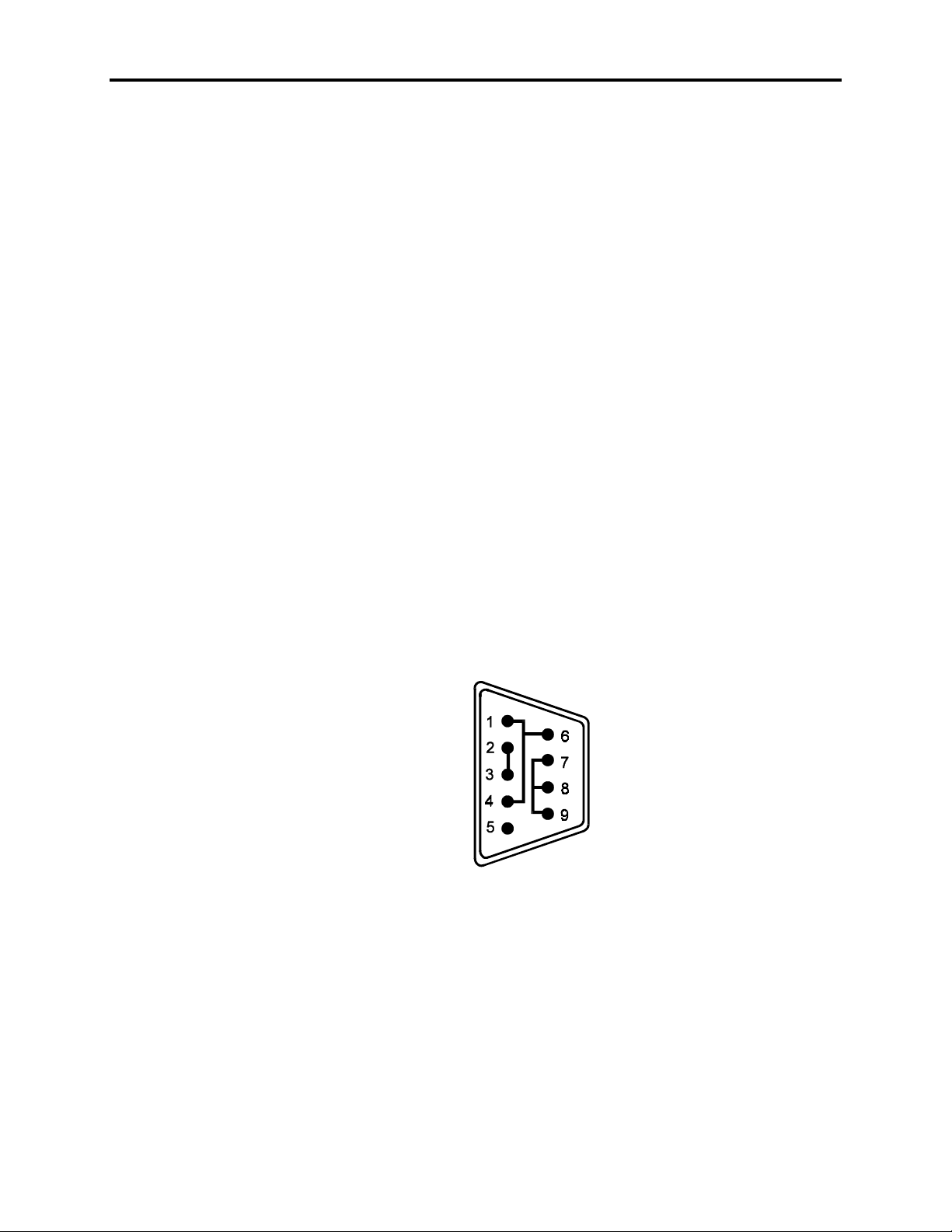
• Two serial loopback test connectors (refer to Figure 2-1 for pinouts)
• Scratch disk—formatted 3.5 -inch, DS/HD (1.44 Mbyte)
Preparing for the Tests
Perform the steps below before starting the system test:
1. Place the CPU board jumpers and switches to the factory-set positions. Refer to the
processor manual for jumper and switch settings. The numbers in parenthesis refer to
the pins onto which to install the jumper, (e.g. J1 (3-4) indicates the jumper is on
pins 3 and 4 of J1).
2. Plug the female end of the AC power cable into the rear of the computer module and
the male end into a properly grounded outlet.
3. Connect the video cable to the 15-pin connectors on the monitor module and on the
processor card in the computer module.
4. Connect the Host/LED 15-pin cable between the Host/LED ports on monitor and
computer modules.
5. Attach the monitor power cord from the monitor to the power receptacle on the back
of the computer module.
6. Connect the serial loopback connector(s) and the printer cable to the appropriate
connectors and connect a PC/AT keyboard to a keyboard connector on the monitor
module. Figure Chapter 2 -1 illustrates the wiring necessary for the loopback connection.
Running the Tests
To run the tests, insert the diagnostics disk into drive A. Turn on the computer and the
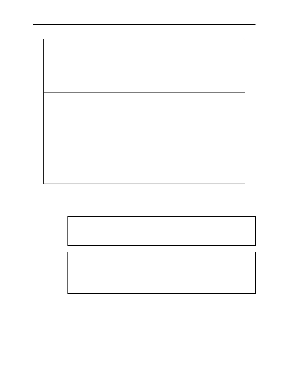
diagnostics program will boot up. Figure Chapter 2 -2 shows the Main Menu as it is displayed on the screen.
Figure Chapter 2 -1. Serial Loopback Connections
2-2
Page 22
Copyright 1990-1994, Xycom, Inc. All rights reserved.
Diagnostic Tests Sequence/Selection Menu (Rel. 1.0)
0) WILL pause on an error 4) Auto-select tests
1) SINGLE PASS test mode 5) Deselect all tests
2) Save setup to file 6) Quit and exit to DOS
3) Extract setup from a file 7) Return to Previous screen
A) RAM Test K) Video Interface Test
B) Video RAM Test L) Speaker Port Test
C) Extended RAM Test M) LPT1: Printer Port Test
D) Real Time Clock Test N) LPT2: Printer Port Test
E) COM1 Serial Port Test O) C: Hard Drive Interface Test
F) COM2 Serial Port Test P) D: Hard Drive Interface Test
G) COM3 Serial Port Test Q) A: Floppy Drive Interface Test
H) COM4 Serial Port Test R) B: Floppy Drive Interface Test
I) Math Coprocessor Test S) Keyboard, Keypad Tests
J) Video Adjustments Test
/
= Test Selected
Chapter 2 – Testing
[ENTER] = START TESTING
Use the letters to move the cursor and select/deselect, or use the arrow keys to move, then use the
[SPACE] key to select/deselect a test or function:
Figure Chapter 2 -2. Main Menu
You can select tests individually. However, we recommend that you use Auto-select (4)
which will select all tests appropriate to your configuration.
Note
Please read the files DIAG.TXT and CMOS.TXT on the diagnostics disk for detailed
information on these tests. Refer to the CMOS.TXT file for BIOS setup information.
Note
If the Solid State (Flash) drive option is used, avoid repeatedly running any hard drive
diagnostic utility on it. The Flash drive has a limited number of writes to each logical
sector over its life span. Repeated writes caused by a diagnostic utility will prematurely shorten the life of the drive.
2-3
Page 23
Chapter 3 – Installation
This chapter discusses how to install options into the 9457 and considerations to take
into account when mounting the monitor and computer modules.
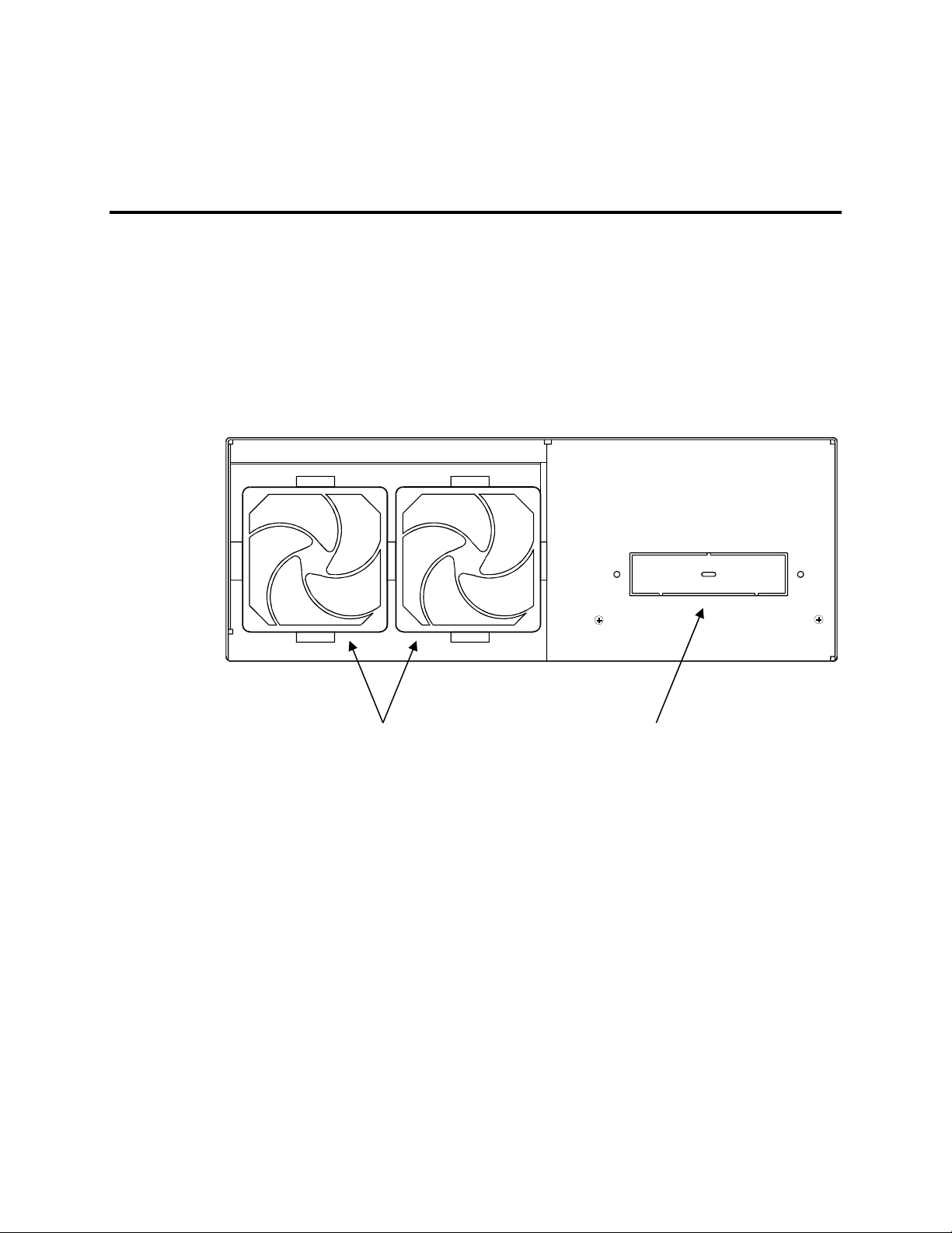
System Components
The figures on this and the next several pages show the internal and external components
on the front and rear of the modules to help you locate features relevant to installing
these modules.
Fan Intake
Filt ers (2)
Figure Chapter 3 -1. 9457 Computer Module Front Components
Front Drive
Bay
3-1
Page 24
9457 Industrial Computer
5.25" Bay
(optional CD-ROM)
100-120V ~ 3A MAX .
200-240V ~ 3A MAX .
3.5"
Floppy
Drive
ON/OFF
Switch
KEYBOARD
Serial
Ports
o
I
C
O
M
1
C
O
M
2
H
O
S
T
/
L
E
D
Cooling
Grille
Power
Receptacle
Monitor Auxiliary
Outlet
Figure Chapter 3 -2. 9457 Computer Module Rear Components
Keyboard
Port
Host/LED
Connector
3-2
Page 25
Chapter 3 – Installation
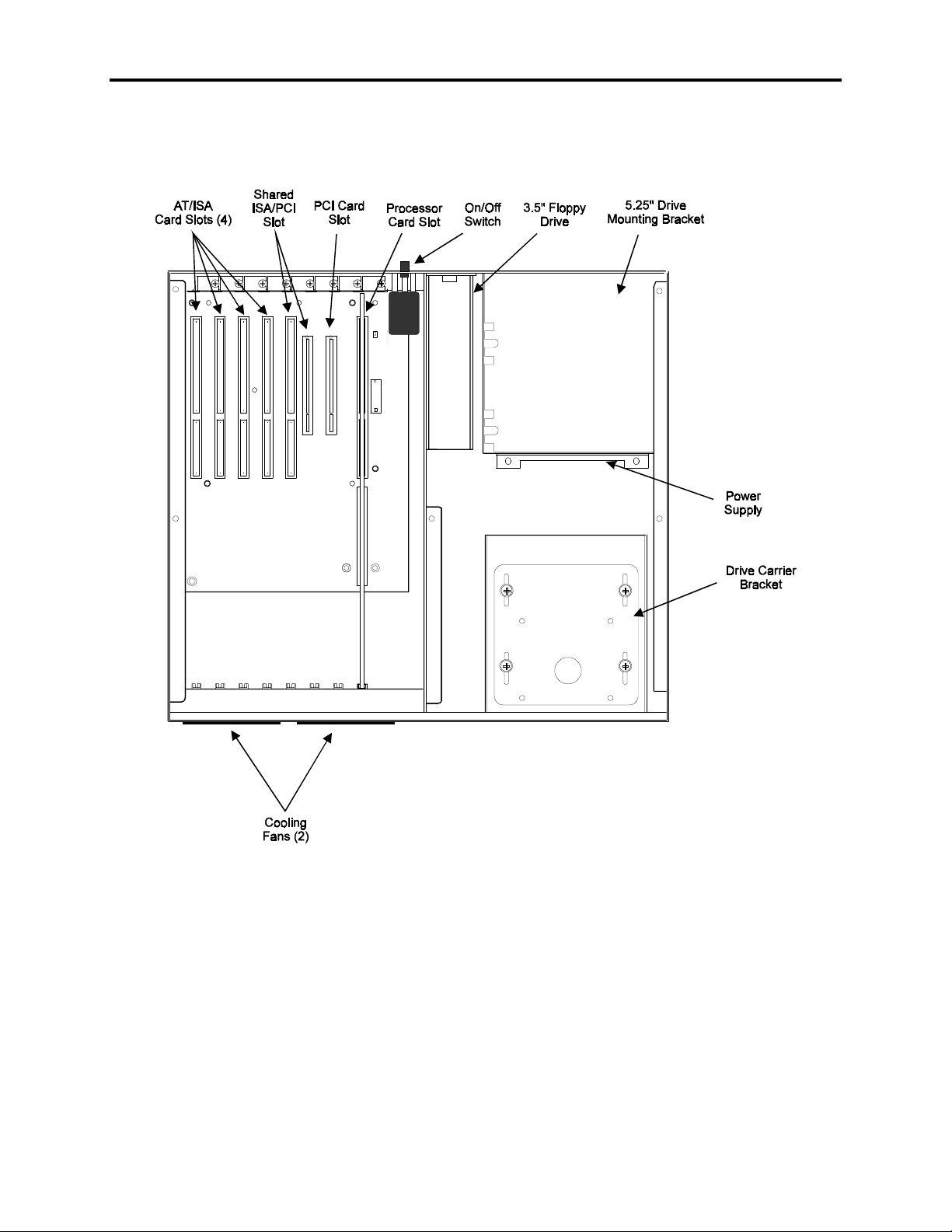
Figure Chapter 3 -3. Computer Module Internal Components
3-3
Page 26

9457 Industrial Computer
Preparing the System for Use
To prepare the system for use, perform the steps listed below. If you purchased any options, install them according to the instructions in the next two sections.
1. Make certain that the power switch on the computer module is turned OFF.
2. Connect the video cable between the 15-pin Video In connector on the back of the
monitor module and the video connector on the processor card in the computer module.
3. Connect the Host/LED 15-pin cable between the Host/LED ports on the monitor
module and the computer module.
4. Attach any other optional equipment following the instructions in
Options
5. Attach the monitor power cord from the monitor to the power receptacle on the back
of the computer module.
6. Attach the power cord from the power receptacle on the computer module to a properly grounded 115/230 VAC, 50/60 Hz outlet.
7. Turn on power to the 9457 by pressing in the On/Off switch on the back of the computer module.
8. Set the contrast and brightness controls on the back panel to the desired levels.
9. Install application software via drive A: located behind the access door on the front
panel.
, later in this chapter.
Installing Internal Hardware Options
Caution
The computer module must be turned off before installing internal hardware.
Internal hardware options may be installed through the top cover of the computer module. If the computer module is mounted to the monitor module, the computer module
must be removed from the monitor module, as described in
Module
, later in this chapter.
Installing External
Removing the Computer
Installation and Removal of the CPU Board
This section describes the steps required to install and remove the CPU board. Some
CPU boards may require additional steps, or specific configuration parameters. Consult
the manual that accompanied your CPU board to determine whether such additional steps
are necessary.
3-4
Page 27

Chapter 3 – Installation
Warning
Disconnect all external power supplies before you open and service any piece of
equipment. Also, always use static protection when handling CPU boards.
Caution
Verify the positions of all jumpers and switches on the CPU board before installation.
Check configurations with the lists and diagrams in the manual that accompanies the
CPU board.
Note
Before connecting a ribbon cable to latched connectors, make sure that the latches are
pulled down near the surface of the board. When the cable connection is made, the
latches snap up. When removing a cable connector, move the latches down near the
board. This nudges the connector up so you can remove it easily.
Installing the CPU Board
1. Disconnect all power supplies from both the monitor and computer modules.
2. If the computer module is mounted to the monitor module, remove the computer
module, as described in
3. Remove the five screws that secure the top cover to the computer module. Save the
screws in a location where you can locate them later.
4. Verify all jumper settings.
5. Hold cables FDD, HDD-I, COM1, COM2, LED and KEYBOARD toward the side of
the CPU module.
6. Place the CPU card into slot 0 in the passive backplane. Push the card down 3/4 of
the way.
7. Attach flat cables FDD, HDD-I, COM1, COM2, LED, and KEYBOARD to the respective connectors on the CPU board. Push down on the card evenly until it firmly
seats into the card edge connector.
8. Secure the ORB with one screw at the top.
9. Close the top cover and re-install and tighten the screws. If the computer module was
mounted to the monitor module, refer to
this chapter, for re-installation instructions.
10. Connect power sources and external cables previously disconnected.
Removing the Computer Module
Replacing the Computer Module
, later in this chapter.
, later in
The 9457 is now ready for operation.
3-5
Page 28

9457 Industrial Computer
Removing the CPU Board
1. Disconnect all power supplies from both the monitor and computer modules.
2. If the computer module is mounted to the monitor module, remove the computer
module, as described in
3. Remove and save the CPU board ORB screw.
4. Unseat the CPU board from the backplane. Pull the board upward just far enough to
unlatch and remove connectors, about 1" (2.5 cm).
5. Remove the cable connectors FDD, HDD-I, COM1, COM2, LED, and KEYBOARD.
6. Once the cables are disconnected, pull the CPU board out of the computer module.
Installing PC Boards
Check that the memory and I/O configuration of the board you want to install does not conflict with the CPU and I/O memory maps, as found in your CPU board manual.
1. Disconnect all power supplies from both the monitor and computer modules.
2. If the computer module is mounted to the monitor module, remove the computer
module, as described in
Removing the Computer Module
Removing The Computer Module
, later in this chapter.
, later in this chapter.
3. Remove the screws from the top cover and open the case.
4. If present, remove the blank ORB from the slot that the PC board will occupy. Save
the screw.
5. Slide the PC board into an open slot in the backplane. Push down on the board
evenly until it firmly seats into the card cage connectors.
Do not force the boards or apply uneven pressure.
6. Secure the board by replacing and tightening the screw that was removed in Step 4.
7. Replace the top cover and replace and tighten the screws that hold it in place. If the
computer module was mounted to the monitor module, refer to
puter Module
, later in this chapter, for re-installation instructions.
Installing the Front Floppy Kit
As shipped, the computer module contains a 3.5" floppy drive mounted for access from
the rear of the unit (see Figure Chapter 3 -2). If you wish to relocate the floppy drive to
the front of the computer module, you must install the 9457-FFK Front Floppy Kit.
Note
Replacing the Com-
3-6
This kit includes the following components:
Page 29

Chapter 3 – Installation
• Rear drive bay cover plate
• Floppy drive access door and mounting hardware for use in panel mounting installa-
tions.
To install the floppy drive on the front of the computer module,
1. Disconnect all power supplies from both the monitor and computer modules.
2. If the computer module is mounted to the monitor module, remove the computer
module, as described in
Removing the Computer Module
, later in this chapter.
3. Remove the five screws that secure the top cover to the case, and open the case.
4. Use a screwdriver to pry out the knockout panel in front of the drive bay. Remove
and discard the knockout panel.
Caution
To avoid injury, be sure to completely remove the knockout tabs from the module
chassis and dress the opening with a file to completely remove any burrs. Take care to
ensure that metal filings do not contaminate the interior of the 9457 case.
5. Locate the floppy drive, at the rear of the case, then disconnect its power and data
cables.
6. Remove the two screws on the module’s rear wall that hold the drive bracket to the
chassis, then slide the drive and bracket forward and up to remove it from the module.
7. Remove the four screws that hold the drive to the mounting bracket. Set the bracket
aside.
8. Remove the four screws that hold the front drive mounting plate to the front drive
mounting bracket, and remove the front drive mounting plate from the case.
9. Mount the floppy drive to the front drive mounting plate by installing the four screws
you removed from the drive mounting bracket in Step 7 through the front drive
mounting plate into the mounting holes on the bottom of the floppy drive.
3-7
Page 30
9457 Industrial Computer
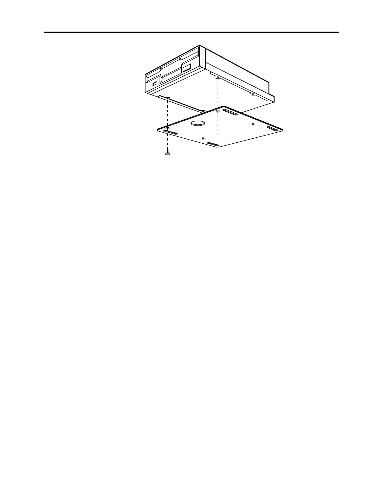
10. Install the assembled drive and mounting plate by placing the assembly back inside
the case so that the mounting slots in the mounting plate align with the screw holes
in the front drive mounting bracket.
Figure Chapter 3 -4. Mounting the Floppy Drive to the Front Drive Mounting Plate
11. Position the front drive mounting plate so that the front of the drive protrudes from
the front of the case as far as you wish. If you will be using the 9457-RFC Rack
Filler with Cutout, the face of the floppy drive must extend 0.5" (13 mm) from the
front of the computer module.
12. Tighten the four screws that hold the mounting plate in place.
13. Reconnect the power and data cables to the drive.
14. Remount the drive bracket and install the rear drive bay cover plate included in the
Front Floppy Kit. Install the cover plate from the inside of the case, securing it in
place between the drive bracket and the case, using the screws removed in Step 6.
15. Replace the top cover and re-install the screws that secure the top cover to the case.
16. Re-install the computer module under the monitor module, if necessary.
Installing the Floppy Drive Access Door
The floppy drive access door is provided for installations using the 9457-RFC Rack
Filler with Cutout, or panel mount installations that provide a cutout for the frontmounted floppy drive. Mount the floppy drive access door to the rack filler plate or the
panel, using the four mounting nuts, as shown in Figure Chapter 3 -5. Torque the nuts to
35 in/lb (3.95 Nm).
3-8
Page 31
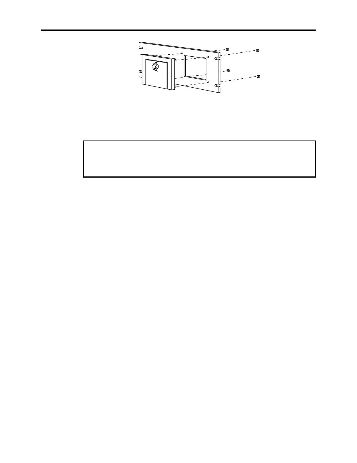
Figure Chapter 3 -5. Mounting the Front Floppy Drive Access Door to the 9457-RFC Rack Filler with Cut-
Installing a Device in the 5.25" Drive Bay
Caution
Use of controls adjustments or the performance of procedures other than those specified herein may result in hazardous radiation exposure.
The 5.25" drive bay located on the rear of the computer module may be used to hold an
externally-accessible 5.25" mass storage device. A CD-ROM drive will occupy this bay
if purchased as an option on this system.
Chapter 3 – Installation
out
To install a device in this bay,
1. Disconnect all power supplies from both the monitor and computer modules.
2. If the computer module is mounted to the monitor module, remove the computer
module, as described in
Removing the Computer Module
, later in this chapter.
3. Remove the screws from the top cover and open the case.
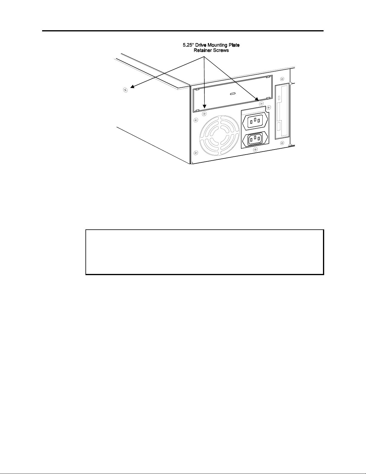
4. Remove the three screws that hold in the 5.25" drive mounting plate. Two are located immediately below the 5.25" drive bay on the rear of the module, and the other
is on the side.
3-9
Page 32
9457 Industrial Computer
z
H
.
0
X
6
/
A
0
M
5
A
3
~
V
0
.
2
1
X
-
0
A
0
M
1
A
3
~
V
0
4
2
-
0
0
2
Figure Chapter 3 -6. 5.25" Drive Mounting Plate Retainer Screw Locations
5. Remove the 5.25" drive mounting plate from its position on top of the power supply.
6. Use a screwdriver to pry out the 5.25" drive bay’s knockout panel out. Remove and
discard the knockout panel.
Caution
To avoid injury, be sure to completely remove the knockout tabs from the module
chassis and dress the opening with a file to completely remove any burrs. Take care to
ensure that metal filings do not contaminate the interior of the computer module case.
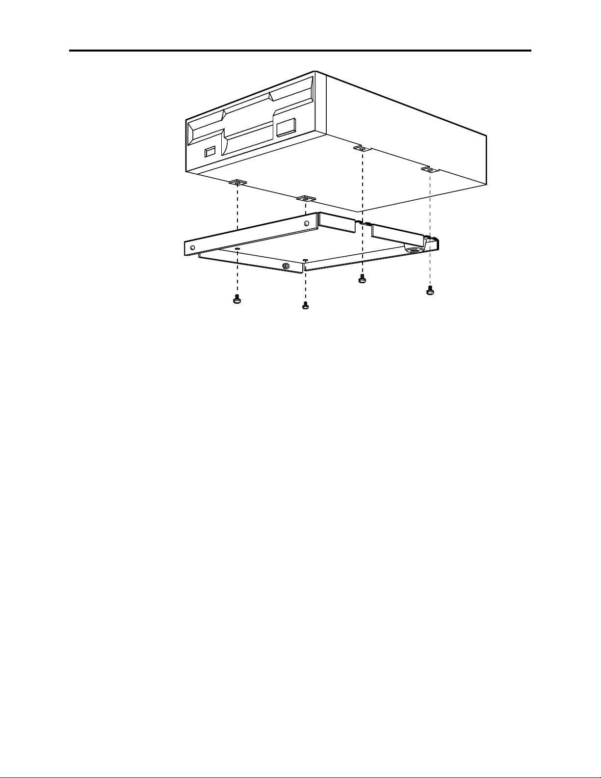
7. Mount the drive to the drive mounting plate by installing four screws through the
drive mounting plate into the bottom of the drive.
3-10
Page 33
Chapter 3 – Installation
Figure Chapter 3 -7. Mounting a 5.25" Device to the 5.25" Drive Mounting Plate
8. Place the assembled drive and mounting plate into the computer so that the drive fits
through the opening on the rear of the case, and the screw holes on the drive mounting plate align with the holes for the three screws removed in Step 4. Re-install the
screws.
9. Install any card and internal cabling required by the new drive. The computer module’s power supply provides extra power connectors which you may use, if needed.
10. Replace the top cover and re-install the screws that secure the top cover to the case.
11. Re-install the computer module under the monitor module, if necessary.
12. Install any driver software required by the new drive.
Installing External Hardware Options
This section explains how to install external hardware options available with the 9457.
Installing the Remote Mount Kit
The 9457-RMK remote mount kit provides the parts necessary to mount the computer
module up to six feet away from the monitor module. This kit contains the following
parts:
• Two remote mounting brackets
• 10 bracket mounting screws
• 72-inch (1.83 m) video cable
3-11
Page 34
9457 Industrial Computer
• 72-inch (1.83 m) monitor power cable
• Two 72-inch (1.83 m) serial cables, for the touch screen and built-in mouse
• 72-inch (1.83 m) Host/LED cable
The remote mounting brackets are designed to be used to mount the computer module to
a shelf or other flat surface, from above or below. They are used to replace the plasticcovered brackets used to mate the computer module to the monitor module.
The brackets may be installed on the module in either of two positions. When installed
along the bottom edge of the module, they allow the module to be mounted to the surface
on which it will sit. When installed in place of the plastic-covered slide brackets along
the top edges of the module, they may be used to hang the computer module on top of or
underneath a shelf or cabinet.
When remote-mounting the computer module, be certain to observe the precautions described in
1. Disconnect all power supplies and cables from both the monitor and computer modules.
2. If the computer module is mounted to the monitor module, remove the computer
module, as described in
General Installation and Mounting Considerations
Removing the Computer Module
, later in this chapter.
, earlier in this chapter.
3. Remove the two screws that hold each of the thumbscrew brackets to the top of the
computer module, then remove the brackets.
4. If you intend to use the remote mounting brackets to replace the plastic-covered slide
brackets along the top of the computer module, remove each of the five screws that
hold the plastic-covered slide bracket to the side of the computer module, then remove the bracket.
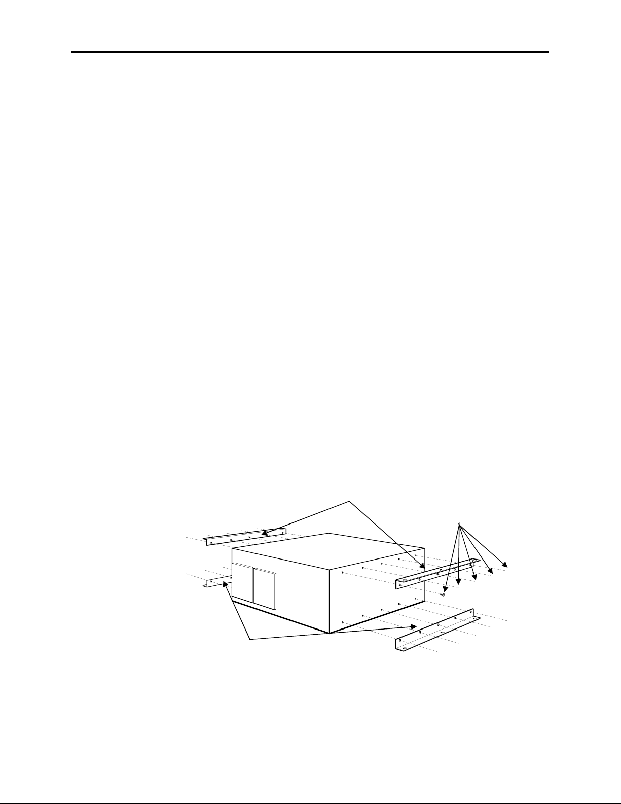
5. Position the bracket from the Remote Mount Kit so that its five screw holes align
with either the top or the bottom set of mounting holes on the computer module, then
mount it using the screws supplied with the Remote Mounting Kit.
Brackets mounted in upper
position (for hanging from a shelf)
Bracket Mounting
Screws (5 per bracket)
3-12
Brackets mounted in lower
(shelf-top mounting) position
Figure Chapter 3 -8. Installing Remote Mounting Brackets
Page 35

6. Turn the computer module around and repeat steps 4 and 5 to replace the bracket on
the other side of the computer module.
7. Once the remote mounting brackets are installed, you are ready to mount the computer module in a suitable location of your choosing. When re-installing the cables
disconnected in Step 1, use the longer cables included with the Remote Mount Kit.
When remote-mounting the computer module, be certain that the surface to which the
module is being mounted is capable of supporting the weight of the computer module,
and that the module is securely fastened in such a manner as to minimize shock and
vibration.
Installing Keyboard Cable Clamps
Two half-clamps are included to provide strain relief for the keyboard cables connected
to the rear of the monitor. To mount these clamps, follow the steps described below.
1. Turn off power to the monitor and your computer.
Chapter 3 – Installation
Note
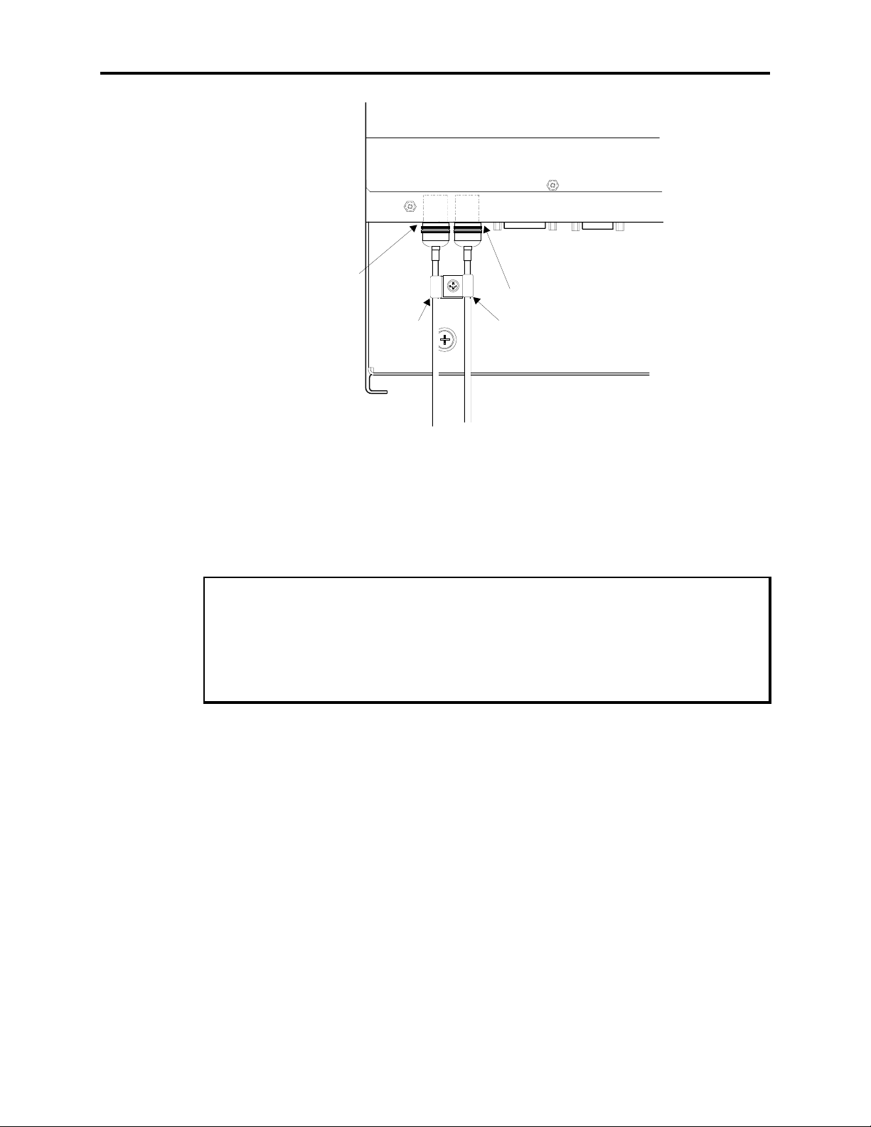
2. If there is a cable connected to the Keyboard In port, place the half-clamp over that
cable and align the half-clamp so that its hole is aligned with the hole immediately
beneath and between the Keyboard In and Keyboard Out ports.
3. If there is a cable connected to the Keyboard Out port, place the half-clamp over that
cable and align the half-clamp so that its hole is aligned with the hole immediately
beneath and between the Keyboard In and Keyboard Out ports.
If you have cables connected to both the Keyboard In and Keyboard Out ports, the
half-clamps should overlap, as shown in Figure Chapter 3 -9.
4. Fasten the clamp(s) using the #6-32 screw provided.
5. Restore power to the monitor and your computer.
3-13
Page 36
9457 Industrial Computer
Keyboar d
In Port
Half-Clamp
Figure Chapter 3 -9. Installing the Keyboard Cable Half-Clamp(s)
Installing Operating Systems
If you want to install a new operating system or re-install a current operating system, refer to the operating system’s manual for instructions.
Note
HOST/LED
Keyboard
Out Por t
Half-Clamp
TOUCH
SCREEN
If the Windows NT™ operating system was preloaded on your system, and you do
not have a CD-ROM drive installed, you may have to purchase and install an internal
CD-ROM driver or an external parallel port CD-ROM drive in order to re-install
Windows NT. This is because Windows NT only ships on CD-ROM.
Installing Drivers
This section describes how to install the drivers associated with the 9457.
Video Drivers
Video drivers are found on the disk included with the documentation kit. Refer to the
README file on this disk for information on installing the video drivers.
Mouse Drivers
The mouse driver software for the built-in industrial mouse will be installed on systems
using Windows 95 or Windows NT. If your system uses Windows NT, OS/2, or MS-
3-14
Page 37

Chapter 3 – Installation
DOS, you will have to install the mouse driver software. Refer to your mouse driver
manual for installation information.
Touch Screen Drivers
If you have purchased the 9457 with the optional touch screen, the touch screen driver
software will be installed on systems using Windows 95. If your system uses Windows
NT, OS/2, or MS-DOS, you will have to install the touch screen driver software. Refer to
your touch screen driver manual for installation information.
CD-ROM Drivers
If you ordered a CD-ROM drive as an option on your system, you will receive a CDROM driver disk. However, the required driver for the operating system you have selected has already been installed. If you change operating systems and need help loading
the required CD-ROM driver, contact Xycom technical support at 1-800-289-9266 x450.
Miscellaneous Drivers
Refer to your operating system and peripheral manuals for information on installing
drivers related to these items.
Note
If you had the Windows NT operating system preloaded on your system and do not
have a CD-ROM drive installed, you may have to purchase and install an internal CDROM drive or an external parallel port CD-ROM drive in order to install Windows
NT drivers. This is because Windows NT only ships on CD-ROM.
General Installation and Mounting Considerations
Once you have found a location for the 9457, install it in the enclosure according to the
manufacturer’s instructions. Consider the following points and precautions before placing the
9457 inside an enclosure:
• Select an enclosure that will allow access to the computer module for maintenance.
• Account for the module’s depth as well as cabling when choosing the depth of the
enclosure
• Mount the 9457 in an upright position.
• Install the unit to ensure that it does not cause a hazard from uneven mechanical
loading.
• Place the 9457 at a comfortable working level.
• Consider the locations of accessories such as AC power outlets and light sources
(interior lighting and windows) for installation and maintenance convenience.
3-15
Page 38

9457 Industrial Computer
• Prevent condensation by installing a thermostat-controlled heater or air conditioner,
if needed.
• Avoid obstructing the air flow to allow for maximum cooling.
• Place any fans or blowers close to the heat generating devices. If using a fan, make
sure that outside air is not brought inside the enclosure unless a fabric or other reliable filter is also used. This filtration prevents conductive particles or other harmful
contaminants from entering the enclosure.
• Do not select a location near equipment that generates excessive electromagnetic in-
terference (EMI) or radio frequency interface (RFI) (equipment such as high power
welding machines, induction heating equipment, and large motor starters).
• Place incoming power lines (such as isolation or constant voltage transformers, local
power disconnects, and surge suppressors) away from the 9457. The proper location
of incoming line devices keeps power wire runs as short as possible, and minimizes
electrical noise transmitted to the 9457.
• Make sure the location does not exceed the 9457’s temperature specifications.
• Avoid overloading the supply circuit. The 9457 is rated at 115/230 VAC at 6.3 Amps.
• Mount the monitor unit to allow for easy access to its rear components if you antici-
pate making frequent adjustments to the display.
The display may be affected by geomagnetic fields. Some typical effects of magnetic
fields are color impurity (blotchy colors), distorted screens, etc. In some cases, purity
problems may be correctable by turning off the unit for 30 minutes and reapplying
power. In other cases degaussing may be required. Contact Xycom’s Technical Support Department for further information at 1-800-289-9266, x 450.
System Power
It is a good idea to use isolation transformers on the incoming AC power line to the 9457. An
isolation transformer is especially desirable in cases in which heavy equipment is likely to introduce noise onto the AC line. The isolation transformer can also serve as a step-down transformer
to reduce the incoming line voltage to a desired level. The transformer should have a sufficient
power rating (units of volt-amperes) to supply the load adequately.
Proper grounding is essential to all safe electrical installations. Refer to the relevant national,
state/provincial and local electrical codes, which provide data such as the size and types of conductors, color codes and connections necessary for safe grounding of electrical components. The
code specifies that a grounding path must be permanent (no solder), continuous, and able to safely
conduct the ground-fault current in the system with minimal impedance. The following practices
should be observed:
• Separate ground wires from power wires at the point of entry to the enclosure. To
Note
minimize the ground wire length within the enclosure, locate the ground reference
point near the point of entry for the plant power supply.
3-16
Page 39

• All electrical racks or chassis and machine elements should be grounded to a central
ground bus, normally located near the point of entry for the plant power supply of
the enclosure. Paint and other nonconductive material should be scraped away from
the area where a chassis makes contact with the enclosure. In addition to the ground
connection made through the mounting bolt or stud, a one-inch metal braid or size #8
AWG wire can be used to connect between each chassis and the enclosure at the
mounting bolt or stud.
• The enclosure should be properly grounded to the ground bus. Make sure a good
electrical connection is made at the point of contact with the enclosure.
• The machine ground should be connected to the enclosure and to earth ground.
Excessive Heat
The 9457 is designed to withstand temperatures from 0º to 50º C (32º to 122º F) and is cooled
by two fans which draw a vertical column of air upward over the surface of the components.
To keep the temperature within this range, the cooling air at the base of the system must not
exceed 50º C. Proper spacing must also be allocated between internal components installed in
the enclosure.
When the air temperature is higher than 50º C in the enclosure, use of a fan or air conditioner
is required to maintain the operating temperature below the maximum rated limit.
Chapter 3 – Installation
Excessive Noise
Electrical noise can cause temporary malfunctions due to operating errors, which can result in
hazardous machine operation in certain applications. Noise may be present only at certain
times, may appear at widely-spread intervals, or in some cases may exist continuously.
Noise usually enters through input, output, and power supply lines and may be coupled into
lines electrostatically through the capacitance between these lines and the noise signal carrier
lines. This usually results from the presence of high voltage or long, closed-spaced conductors. When control lines are closely spaced with lines carrying large currents, the coupling of
magnetic fields can also occur. Use shielded cables to help minimize noise. Potential noise
generators include relays, solenoids, motors, and motor starters, especially when operated by
hand contacts like push buttons or selector switches. In accordance with National Electric
Code specifications, it is recommended that the high voltage and low voltage cabling be separated and dressed apart. In particular, the AC cables and switch wiring should not be in the
same conduit with PLC communication cables.
Excessive Line Voltage
The power supply of the 9457 is built to sustain line fluctuations within ranges from 90-131
VAC or 182-264 VAC and still allow the system to function within its operating margin. As
long as the incoming voltage is adequate, the power supply provides all the logic voltages
necessary to support the processor, memory, and I/O.
In cases in which the installation is subject to unusual AC line variations, a constant voltage
transformer can be used to prevent the system from shutting down too often. However, a first
3-17
Page 40
9457 Industrial Computer
step toward the solution of the line variations is to correct any possible feed problem in the
distribution system. If this measure does not solve the problem, a constant voltage transformer
must be used.
The constant voltage transformer stabilizes the input voltage to the 9457 by compensating for
voltage changes at the primary in order to maintain a steady voltage at the secondary. When
using a constant voltage transformer, check that the power rating is sufficient to supply the
9457.
Installing the System into a Panel
The 9457’s rugged design allows it to be installed in most industrial environments. The 9457
is generally placed in a NEMA 4/4X/12 enclosure to protect against contaminants such as
dust, moisture, etc. Metal enclosures also help minimize the effects of electromagnetic radiation that may be generated by nearby equipment.
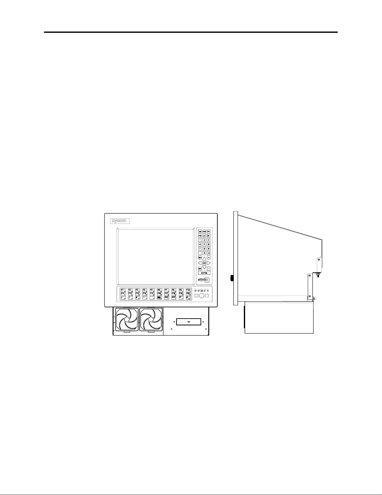
The 9457 is designed to be installed in one of two basic ways. The most common and most
compact configuration entails mounting the computer module directly beneath the monitor
module in a panel installation. This configuration uses 18-inch (457 mm) cables between the
computer module and the monitor module.
3-18
Figure Chapter 3 -10. 9457 Monitor And Computer Modules Mounted Together
In this configuration, the combined monitor and computer modules occupy a minimal
amount of space.
The second configuration permits mounting the monitor module up to six feet (1.8 m)
away from the computer module, using 72-inch (1.82 m) cables. The computer module
may be mounted in any position relative to the monitor module, so long as it is mounted
upright and is provided adequate ventilation. This requires installing the 9457-RMK
Remote Mount Kit, as described earlier in this chapter.
Page 41
)
(
)
1.105
(28.1)
(222.2)
Chapter 3 – Installation
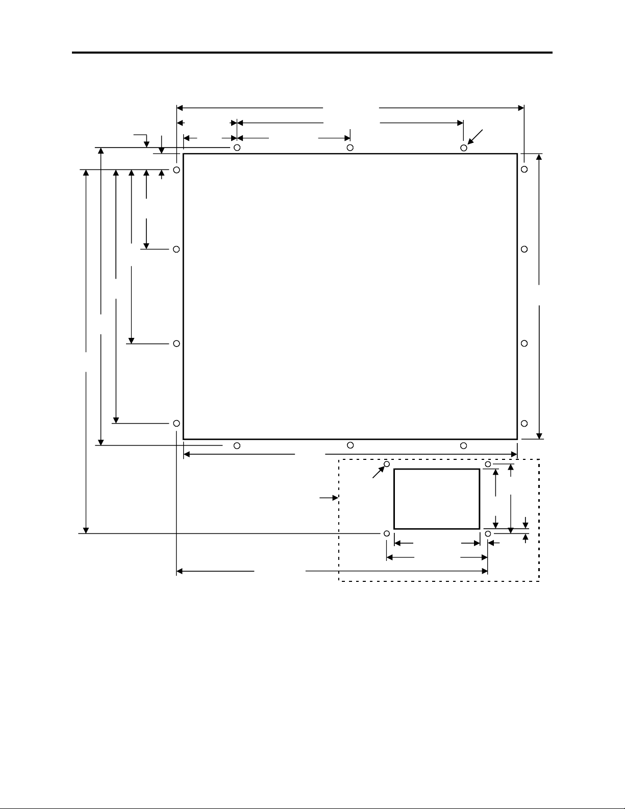
The 9457 monitor module fits into a panel cut-out that has the following dimensions:
465.1
18.312
12.00 (304.8)
8.75
4.00
(101.6)
.795
(20.2)
3.156 (80.2)
2.815
(71.5)
6.00 ( 152.4)
.25(6.35) dia.
14 places
18.26
(463.8)
14.96
(380.0)
12.75
(323.9)
Optional f ront
floppy door
16.47 (418.3)
17.63
(447.8)
cutout
.10 (2.54) dia.
4places
4.50 (114.3)
5.38 ( 136.7)
3.00
(76.2)
3.50
(88.9)
.44
(11.2)
.25
(6.35)
14.34
(364.2
Figure Chapter 3 -11. 9457 Monitor Module Cutout Dimensions
When panel mounting the 9457, if you intend to mount the computer module beneath the
monitor module, you must allow at least 6 inches (152.4 mm) additional clearance beneath the monitor module.
3-19
Page 42
9457 Industrial Computer
To mount the monitor module, follow the instructions below:
1. Locate a position for your 9457 that meets the unit’s operating specifications. Refer
to Appendix A and the previous sections in this chapter for these values.
2. Add the cutout (as shown in Figure Chapter 3 -11) to the enclosure. To provide a
NEMA 4/4X/12 seal, the unit must be mounted in an approved enclosure with a
14 gauge (.075"/1.9mm minimum thickness) steel or (.125"/3.2 mm minimum thickness) aluminum front face.
If you intend to install the front floppy door, cut and drill the panel to include the
cutout for this door, shown as optional in Figure Chapter 3 -11.
3. Make sure the area around the cutout is clean and free from metal burrs.
4. Implement the proper grounding techniques. Establish a ground path from the 9457
chassis to the enclosure chassis.
To make a proper ground, scrape paint off the inside of the enclosure panel around
mounting stud holes (in at least two places) at opposing ends of the unit. This insures
that a good electrical connection is made between the chassis and the grounded metal
panel.
Note
5. Install the monitor module into the cutout. Torque the 14 mounting nuts to 35 in/lbs
(3.95 Nm).
6. Re-attach the computer module.
7. If you have mounted the floppy drive for access from the front of the computer module, and have purchased the 9457-FFK Front Floppy Kit, mount the floppy drive access door provided with the kit to the panel. Do this in the manner shown in Figure
Chapter 3 -5. Torque the nuts provided with the door to 35 in/lb (3.95 Nm).
Mounting the Computer Module to the Monitor Module
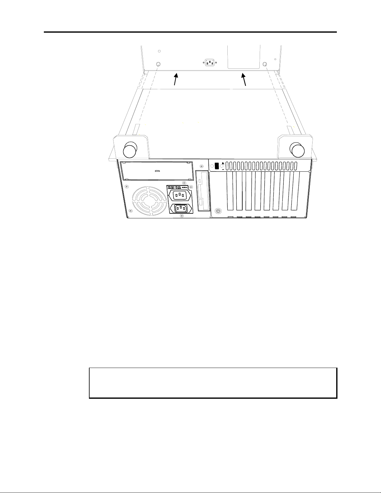
The 9457 computer module is designed so that it may be slide-mounted underneath and
hung from the monitor module, once the monitor module has been installed in a panel.
To mount the computer module to the monitor module, perform the steps described below.
1. Mount the monitor module in a panel, as described above.
2. Verify that the top panel of the computer module is securely in place.
3. Line up the flanges at the top side edges of the computer module with the tracks on
the lower side edges of the monitor module, as shown in Figure Chapter 3 -12, and
slide the monitor module onto the computer module.
4. Thread the two thumbscrews on the brackets on the back of the computer module
into the monitor module, then tighten them firmly.
3-20
Page 43
Chapter 3 – Installation
Figure Chapter 3 -12. Mounting the Computer Module to the Monitor Module
Removing the Computer Module
Follow the steps listed below to remove the computer module from the monitor module.
It is not necessary to remove the monitor module from its mounting to remove the computer module.
1. Disconnect all power supplies from both the monitor and computer modules.
2. Disconnect the video, power, Host/LED, printer, touch screen and mouse cables. If
you have connected an external keyboard to the computer module, disconnect that
too.
3. Loosen the two thumb screws that attach the computer module to the monitor module back panel.
4. Grasping the sides of the computer module, pull straight back. The computer module
should slide out easily.
Place a hand underneath the computer module to support its weight.
Note
5. Place the computer module on a flat, level surface.
3-21
Page 44
9457 Industrial Computer
Derating the Power Supply
On the average, the temperature within the 9457 is 7-10°C higher than that outside the
enclosure. When the ambient (exterior) temperature reaches 42°C, the system’s power
supply will begin to derate at a rate of 3.25 watts per increase of 1°C. The 9457 is rated
to work at temperatures up to 50°C. At 50°C, the power supply should be derated to
125 W of total power available for expansion cards with an AT5+ processor board installed. Refer to Table Chapter 3 -1 for more information.
Total current available for expansion cards after derating at 50°C ambient outside temperature (not to exceed 125 W):
Table Chapter 3 -1. Available Expansion Current
Voltage Available Current
+5 VDC 16.90 A
+12 VDC 7.00 A
-12 VDC 0.48 A
-5 VDC 0.50 A
3-22
Page 45
Chapter 4 – System Operation
Using the Keypads
Some configurations of the 9457 monitor module feature both a 30-key function/alpha
keypad and a 28-key numeric and cursor control keypad. When the Host/LED cable is
properly connected, these keypads may be used in the same fashion as you would use a
conventional keyboard when running applications on the 9457.
The monitor module contains circuitry that allows you to use its built-in keypads, even
when a keyboard is plugged into one of the keyboard ports on the monitor module.
Caution
Do not connect a keyboard to the keyboard port on the back of the 9457 computer
module if the computer module is connected to the monitor module using the
Host/LED cable. Doing so may cause the keyboard to function improperly.
The function keypad acts as both a function and an alphanumeric keypad. Initially, the
keypad acts as function keys F1 through F20, and the punctuation and special function
keys printed on the keys in white. To change the function keypad to an alphanumeric
keypad, press the F/A key. When the keypad is set to alphanumeric mode, the LED on
this key is lit. To toggle the keypad to act as function keys, press the F/A key again.
The 9457 allows you to reprogram the keypad. Refer to Chapter 5 for information on
how to do this.
Using the Built-in Mouse
Some configurations of the 9457 monitor module feature a built-in serial mouse, located
in the lower right corner of the front panel, beneath the system status LEDs. When the
proper serial cable is connected from the mouse port on the back of the monitor module
to a serial port on the computer module, the built-in mouse can be used in the same manner as you would use a conventional mouse when running applications on the 9457.
4-1
Page 46

9457 Industrial Computer
The built-in mouse consists of three basic parts:
Left Mouse Key
Mouse Dome
Right Mouse Key
System Status LEDs
The 9457 monitor module features five status LEDs on its front panel, which you can use
to monitor system operation. To use these LEDs, you must have installed the Host/LED
cable between the monitor module and the computer module.
The System Status LEDs are
Fault
Maint
Power
This key serves the same function as the left button on a conventional mouse.
This dome is used to move the mouse pointer around the screen.
Press the edge of the dome that corresponds to the direction in
which you wish to move the pointer.
This key serves the same function as the right button on a conventional mouse.
Lights when an error is detected during the Power On Self-Test, as
described below.
Lights when the computer module has been used for a sufficient
number of hours to require routine maintenance.
Lights when power is applied to the computer module.
Disk
Com
Lights when the computer module accesses the hard drive.
Lights when there is communication activity on one of the computer module’s serial ports, including communication between the
computer module and the built-in mouse or optional touch screen
on the monitor module.
During power-up, firmware on the processor board checks the hardware configuration
against the configuration information stored in the CMOS memory. If the Power On SelfTest (POST) is successful, the Maint and Fault LEDs will be extinguished. The Maint,
Fault and Power LEDs indicate the system’s status as follows:
Table Chapter 4 -1. System Status LEDs
Fault Maint Power Condition
Off Off Off No power
Off Off On System in reset prior to POST
Off On On Running POST
On Off On Failed POST
Off Off On Passed POST
4-2
Page 47

Adjusting the Monitor
As shipped, the monitor module supports display of a number of common video formats.
These formats correspond to those output by video circuitry on the AT5+ processor
board. Their parameters are described in Appendix A of this manual.
The settings on the monitor module are adjusted using the menu-driven On-Screen Display mode. This mode allows you to adjust the display area width, horizontal phase, display area height, and display area shape characteristics, as well as the input source, sync
polarity, and horizontal and vertical frequencies.
To adjust the monitor, follow these steps:
Chapter 4 – System Operation
1. Press the On-Screen Display mode button (
module. The On-Screen Display menu will appear on the screen, with five icons corresponding to the five display adjustment buttons located on the back panel of the
monitor module. These icons are arranged from left to right in the order that the
buttons would appear if you could see them through the face of the monitor. A button may serve different purposes on different menus, as indicated by the icons associated with that menu. The button closest to the center of the monitor module, the
Degauss button (
2. The menu features four options, as described below. Press the buttons corresponding
to the direction you wish to move the highlight bar across the menu.
3. When you have made the desired adjustments, press the Degauss button (
the new settings.
), uniformly acts as the Escape button on all menus.
On-Screen Display Mode Options
The four options available from the menu that appears when you select On-Screen Display mode are as follows:
Geometry
This option allows you to adjust display width, horizontal phase, height, vertical shift,
pincushioning, keystoning and bowing. These are adjusted using a series of icons and bar
graphs.
), located on the rear of the monitor
) to store
Horizontal Width
Horizontal Centering
Vertical Height
Press the buttons corresponding to the arrows pointing left
and right to adjust the width of the display area on the
screen.
Press the buttons corresponding to the arrows pointing left
and right to adjust the horizontal position of the display area
on the screen.
Press the buttons correspond to the arrows pointing up and
down to adjust the height of the display area on the screen.
4-3
Page 48

9457 Industrial Computer
Vertical Centering
Press the buttons corresponding to the arrows pointing up
and down to adjust the vertical position of the display area
on the screen.
The Geometry2 option displays a menu of four icons that corresponding to attributes of
the display area on the screen. These are
Bowing
Press the buttons corresponding to the minus (-) and plus (+)
signs to adjust the amount that the edges of the display area
bow to the left or right on the screen.
Keystoning
Press the buttons corresponding to the minus (-) and plus (+)
signs to adjust the amount that the display area on the screen
tapers from the top to the bottom.
Parallelogram
Press the buttons corresponding to the minus (-) and plus (+)
signs to adjust the amount that the corners at the left and
right edges of the screen are skewed from each other.
Pincushioning
Press the buttons corresponding to the minus (-) and plus (+)
signs to adjust the degree to which the display area bulges
both vertically and horizontally on the screen.
Color
This option allows you to adjust color temperature and the baseline color levels of the
monitor module.
Color Temperature
Press the buttons corresponding to the minus (-) and plus
(+) signs to select the temperature range setting you wish to
use or that you wish to adjust. Your choices are 93K, 65K,
or User.
Red Level
Press the buttons corresponding to the minus (-) and plus
(+) signs to adjust the baseline amount of red that is mixed
into the colors displayed on the screen.
Green Level
Press the buttons corresponding to the minus (-) and plus
(+) signs to adjust the baseline amount of green that is
mixed into the colors displayed on the screen.
Blue Level
Press the buttons corresponding to the minus (-) and plus
(+) signs to adjust the baseline amount of blue that is mixed
into the colors displayed on the screen.
4-4
Page 49

Chapter 4 – System Operation
Reset
This option restores the factory default settings. You will be prompted to confirm that
you wish to reset. Press the button corresponding to “Y” to confirm, or the button corresponding to “Esc” (the Degauss button) to cancel the reset operation.
Note
Selecting the Reset option erases all custom settings you have saved in the monitor.
Special
This option provides access to several voltage level settings. In normal operation, you
should not need to adjust these settings.
Caution
Do not adjust the settings on the Special menu, except under the instruction of a Xycom application engineer. Indiscriminately changing the values on this menu may result in damage to the monitor module or equipment connected to it.
Power Management Modes
The 9457 monitor module conserves energy by operating in the three modes listed below. It automatically switches between these modes based upon the presence of vertical
or horizontal sync signals.
Normal Mode
This is the normal operating mode the monitor enters at start-up. The monitor remains in
Normal mode so long as both vertical and horizontal sync signals are present.
Standby Mode
The screen is blanked immediately when the horizontal or vertical sync signal is removed
from the monitor for more than five seconds. From standby mode, the monitor will instantaneously return to Normal mode upon restoration of the horizontal and vertical sync
signals.
4-5
Page 50

9457 Industrial Computer
Suspend Mode
In this mode, the monitor consumes less than 30 Watts. The monitor enters Suspend
mode, shutting down its internal horizontal timers, after it has been in Standby mode for
five seconds. From Suspend mode, it may take up to three seconds for the monitor to return to Normal mode.
Degaussing the Monitor
Under normal operating conditions, the monitor should not require manual degaussing,
since it is automatically degaussed each time the monitor is powered up. However, if you
should wish to manually degauss the monitor, follow these steps:
1. Turn on the computer and operate both it and the monitor for at least 30 minutes.
2. Depress the Degauss button (
gauss itself automatically.
Once you have degaussed the monitor, you will be unable to degauss it again until you
have operated the monitor for 30 minutes.
), located on the rear panel. The monitor will de-
4-6
Page 51

Chapter 5 – Programmable Keypad Utility
Program
A Keypad Utility Program circuit is integrated into the front panel of the 9457. This lets
users redefine all keypad keys with new scan codes using utility software.
An external full-stroke PC/AT keyboard is used to access the utility. (You are unable to
redefine this keyboard.)
Note
The keypad switch arrays are disabled while the Programmable Keyboard Interface
Module (PKIM) utility is running.
Loading the Programmable Keypad Utility
You can run the PKIM utility from the disk or copy it onto your hard drive. To run the
utility from the disk, change the directory to the appropriate drive and type PKIM. To
load the utility onto your hard drive, create a subdirectory for the files, and copy all the
files on the disk into that subdirectory. Enter the subdirectory and type PKIM.
Using the Programmable Keypad Utility
The PKIM utility uses a menu bar and pull-down menu system. All menu bars are displayed across the top of the screen. “Xycom PKIM Utility” and the current menu title are
shown at the bottom of the screen (see Figure Chapter 5 -1).
A full-stroke keyboard is needed to enter keystrokes while recording a new key macro,
editing an existing macro, and entering utility commands. All keys on the keypads are
redefinable. While the utility is running, the keypads are disabled.
Dialog boxes appear for user prompts and to display error and user advice messages.
Two keys can be used to exit from the menus:
•
•
The keys specific to each menu are shown at the bottom of each screen.
moves to the previous menu or out of the utility from the Main Menu.
ESC
1 returns to the current menu headings in some of the menus where Exit can be
F
chosen to exit this menu.
5-1
Page 52

9457 Industrial Computer
Startup
This section describes the startup options for the utility.
PKIM [/r | /t] runs the full PKIM utility
/r equals reduced functionality. Some keyboard controllers will not allow the PKIM utility to have control. In this case, keycodes uploaded from the EEPROM cannot be translated correctly. Starting the utility with the /r switch removes the Upload option from the
Main Menu. In this mode, editing must start with macros read in from a file since they
cannot be read from EEPROM.
/t equals translate. Some systems initialize the keyboard to run in XT mode. In this case,
the scan codes read in from the keyboard when in Teach mode will not be correct unless
the utility is started with the /t switch.
Utility Batch Mode
Versions 2.2 and above of the utility include a mode for reprogramming keypads from a
batch file. This feature is useful if you wish to reprogram many units with customized
keypad macros without having to enter the full PKIM utility for each unit. Once the full
utility has been used to create and save keypad macros, the files containing these macros
can be included on a disk with the PKIM utility and then used to reprogram other units
from a batch file.
PKIM filename - runs the PKIM utility batch mode where filename is the file containing the new keypad macros. The filename extension must be included.
Example:
PKIM newdef32.pkm
In a batch file, this will reprogram the default values for the numeric keypad.
You may also specify multiple macro filenames in the PKIM line.
Example:
PKIM newdef32.pkm 20funcff.pkm
This will reprogram both the numeric and the function key keypads.
5-2
Page 53
Chapter 5 – Programmable Keypad Utility Program
Main Menu
The Main Menu provides six selections: Exit, Files, Macros, Upload,
Download, and Utilities. The Main Menu is shown in Figure Chapter 5 -1.
Exit Files Macros Upload Download Utilities
Xycom PKIM Utility: MAIN L-Arrow, R-Arrow, Enter
Figure Chapter 5 -1. Main Menu
Exit
Files Menu
Each of the Main Menu selections is described in separate sections below.
Exit closes open files and exits the utility.
exiting the other menus.
Files containing keypad macro sets (a macro for each key) may be saved on disk and
loaded into memory to view, edit, or download to the PKIM. Some of these files may be
included in the utility package for use in reconfiguring the keypads for different software
packages and as templates for defining completely new keypad macro sets.
When you choose Files, a pull-down menu is displayed that provides the following
choices: Open, Close, Save, Save As, Delete, and Exit.
can also be used for this purpose and for
ESC
Open
Opens a file that contains a macro set for one of the keypads and loads the contents into
memory. Any macro set in memory is overwritten. Once loaded, the macro set is available to edit, view, teach, and/or download to the PKIM.
Close
Clears the macro set from memory and closes the file from which they came.
5-3
Page 54
9457 Industrial Computer
Save
Copies the macro set from memory back into its original file. The original file contents
are overwritten.
Save As
Creates a new file under the specified name and copies the macro set from memory into
it. For example, to define different sets of codes, save each set under a different name
and download the one you wish to use.
Delete
Deletes a file.
Exit
Returns to the Main Menu.
Macros Menu
When you select Macros, a menu bar displays four choices: Exit, View, Teach,
and Edit.
You must have a macro file in memory before the Macros Menu is available. To load
a macro file, either Open a file or Upload a file.
Exit
Returns to the Main Menu.
View
Allows viewing the macro for the selected key without having to worry about an accidental change to the macro. When View is chosen, the Exit option and the state of the
click (clicks are not supported on the 9457) are displayed on the menu bar and a graphic
representation of the chosen keypad is shown. Select
to the Macros Menu.
To select a key to view, use the arrow keys to position the cursor on the desired key and
press
ENTER
Note
from the View Menu to return
EXIT
.
5-4
The macro is displayed as two lines—ASCII and code. The ASCII line displays each
keycode as the keys it represents on the full stroke keyboard. Special labels are used for
certain keys (e.g., Spc for space bar, UAr for up arrow, and bk for the break code prefix).
The code line is displayed in either Hex or decimal, as explained below. There is a one-
Page 55

Chapter 5 – Programmable Keypad Utility Program
to-one correspondence between the ASCII and code lines to help you interpret the code
line.
The menu bar displayed while viewing the macro offers two options: Exit and
Hex/Decimal.
Exit
Returns to View menu.
Hex/Decimal
Toggles between displaying the macro in hex or decimal format. Default is Hex. When
Hex is chosen, keycodes are displayed as they are in memory—hexadecimal value scan
codes. When Decimal is chosen, keycodes are displayed as the decimal equivalent of the
hex codes.
For example, the macro
would be displayed as 1C F0 1C 32 F0 32 21 F0 21 in hex,
abc
and 28 240 28 50 240 50 33 240 33 in decimal.
Teach
Allows you to record up to 105 key strokes in a macro. When Teach is selected, a
graphic representation of the keypad currently in memory is displayed. Menu bar choices
are Exit, ASCII/Hex/Decimal, and Click ON/OFF.
Exit
Returns to Macros menu.
ASCII/Hex/Decimal
Chooses the format to display the keystrokes as they are entered. Default is ASCII.
Click
Not supported on the 9457.
ON/OFF
To select a key to define, use the arrow keys to position the cursor on the desired key and
press
ENTER
. After a key is selected, the utility records every key stroke on the external
full stroke keyboard into a macro to be assigned to the chosen key. As the keys are entered they are displayed using the chosen format.
turn to the Teach Menu, so it is not a recordable key. However,
is used to stop recording and re-
ESC
can be included in a
ESC
macro by using the editor.
5-5
Page 56

9457 Industrial Computer
The changes made to the macros in the Teach Menu are not programmed until you
select Download.
Edit
Displays a graphic representation of the keypad in memory and a menu bar displaying
Exit and Click ON/OFF.
Exit
Returns to the Macros Menu.
Click
Not supported on the 9457.
ON/OFF
Note
To select a key to edit, use the arrow keys to position the cursor on the desired key and
press
ENTER
.
In edit mode, the macro is displayed as two lines. The top line (the edit line) displays the
macro in either hex or decimal format and is the line in which the actual editing takes
place. The bottom line (the ASCII line) displays the macro in ASCII format and is not
user configurable. This line helps keep track of which part of the macro you are editing,
and will be updated by the utility as editing takes place.
For example:
edit line-> 1275F075F0121CF01C1222F022F012 0
ASCII line-> sh 8 bk 8 bk sh a bk a sh X bk X bk sh EOM
The insert, delete, and cursor control keys are active for editing.
When a key is selected, the menu bar displays the following choices: Exit, Cut,
Copy, Paste, Codes, Hex/Decimal, and I/O (Insert/Overtype). The
macro for the chosen key is also displayed.
Cut
Deletes a sequence of scan codes from the macro. To select a section to cut:
1. Place the cursor on the first character to cut.
2. Press
1 and select
F
CUT
.
5-6
3. Press
. Cut should still be highlighted, but the cursor will appear on the Edit
ENTER
line. Move the cursor on the last character to cut and press
ENTER
.
Page 57

Chapter 5 – Programmable Keypad Utility Program
4. The last character of every macro is the end of the macro (EOM) and cannot be deleted.
Copy
Copies a sequence of scan codes from the macro into memory. To select the section to
copy:
1. Place the cursor on the first character to copy. Press
2. Press
. Copy should still be highlighted, but the cursor will appear on the Edit
ENTER
1 and select Copy.
F
line.
3. Move the cursor on the last character to copy and press
ENTER
.
The copied item does not appear on the screen until you select Paste.
Paste
Inserts a sequence of scan codes (which were saved in memory using Copy) into the
macro. To paste a sequence of scan codes that were previously copied, position the cursor where you want the text to appear and then press
ENTER
.
1. Select Paste and then press
F
Codes
Displays a table of keys and their scan codes in Hex. See Codes section in this chapter
for a complete code listing.
Hex/Decimal
Toggles between displaying the scan codes in Hex and Decimal formats.
Insert
Toggles between insert and overtype mode.
Upload Menu
Use the Upload Menu to choose which keypad macro information to load. Choices in
this menu are Function keypad, Numeric keypad, Keyboard, PKIM version, and Exit.
Function Keypad
Commands the PKIM to send its entire macro set for the function key keypad.
Numeric Keypad
Commands the PKIM to send its entire macro set for the numeric key keypad.
5-7
Page 58

9457 Industrial Computer
Keyboard
Commands the PKIM to send its entire macro set for the switch array keyboard. (The
9457 does not support the ability to reprogram switch array keyboards. You may choose
to upload a keyboard, but the keys will not be defined.)
PKIM Version
Commands the PKIM to send its firmware revision number.
Exit
Returns to the Main Menu.
Only one macro set may reside in memory at one time. Also, Upload is not available
if the utility is started with the /r switch
Note
A checksum will be calculated during transmission and an error message displays if an
error occurs.
Download Menu
Any macro set previously programmed is overwritten when you select Download.
Download sends the set of keypad macros to the PKIM. The macro set must reside in
memory before it can be downloaded. A checksum is calculated during transmission and
an error message displays if an error occurs.
As the macro is sent, PKIM programs its EEPROM with the new macros which become
the new key definitions for the selected keypad.
Utilities Menu
When Utilities is selected, a menu bar displays four choices: Func Lock ON, Func
Lock OFF, Clear EEPROM, and Exit.
Note
5-8
Page 59

Chapter 5 – Programmable Keypad Utility Program
Func Lock ON
Turns on the function key interlock feature. The function key interlock disables all function keys as long as one function key is pressed (only one function key can be activated
at one time).
Func Lock OFF
Turns off the function key interlock feature, allowing multiple function key presses.
Clear EEPROM
Erases the EEPROM memory. This clears the entire keypad macro set, the contrast setting, the backlight timeout setting, and the function key interlock setting. After using this
feature, the unit should be turned off and then on. This will initialize the EEPROM with
the default settings.
Exit
Returns to the Main Menu.
5-9
Page 60

9457 Industrial Computer
Codes
Special PKIM codes replace the standard IBM scan codes for 101-key keyboard enhanced keys in macros that use these keys. The special scan codes are listed in Table
Chapter 5 -1:
Table Chapter 5 -1. Special PKIM Scan Codes
Code Meaning
E2
E3
E4
E5
E6
E7
E8
E9
EA
EB
EC
ED
EE
Insert
Home
Page Up
Delete
End
Page Down
Up Arrow
Left Arrow
Right Arrow
Down Arrow
Forward Slash
Print Screens/Sys Rq
Pause/Break
Table 5-2 lists the default keypad keycodes produced by the PKIM utility.
5-10
Page 61

Chapter 5 – Programmable Keypad Utility Program
Table Chapter 5 -2. Default Keypad Keycodes
*
=
+
-
“
-
”
“
-
”
“
-
”
“
-
”
5-11
Page 62

9457 Industrial Computer
5-12
Page 63

Chapter 6 – Maintenance
Preventive Maintenance
The 9457 was designed to withstand the harsh environment of the factory floor. Routine
maintenance can help keep your 9457 in good operating condition. Preventive maintenance consists of several basic procedures and checks that will greatly reduce the
chances of system malfunction. Preventive maintenance should be scheduled along with
the regular equipment maintenance to minimize 9457 down time.
Some preventive measures are listed below.
• Clean or change the fan filters periodically to ensure that the air circulating in the
unit is clean. Filter maintenance should not be put off until the scheduled maintenance, but should be performed periodically, depending on the amount of dust in the
area.
• Remove dust and dirt from PC components. If dust builds up on heat sinks and cir-
cuitry, the resulting reduction in heat dissipation could cause the unit to malfunction.
If dust reaches the electronic boards, a short circuit could occur.
• Check the connections to I/O modules, especially in environments where shock
could loosen the connections. Check to see that all plugs, sockets, terminal strips,
and module connections are solid.
• Do not move noise-generating equipment too near the 9457.
• Stock spare parts to minimize down time resulting from part failure. The spare parts
stocked should be 10 percent of the number of each unit used. There should be one
spare CPU card each, regardless of the number of CPUs used. Each power supply
should have a back-up. In certain applications where immediate operation of a failed
system is required, an entire spare unit may need to be stocked. See the spare parts
list in Table Chapter 6 -5.
• When replacing a module, make sure it is the correct type. If the new module solves
the problem, but the failure re-occurs, check for inductive loads that may be generating voltage and current spikes that may require external suppression.
6-1
Page 64

9457 Industrial Computer
Care of the 9457 Cabinet
Never clean the 9457 while power is on. Disconnect the monitor power cord before
cleaning. Avoid spraying liquids into the ventilation slots.
Do not use screen cleaning products that are abrasive or are designed to leave a coating or residue, such as “anti-static screen coatings.” These products may damage the
anti-reflective treatment on the screen face.
Never use petroleum-based or abrasive cleaners.
To clean the exterior of the 9457, dampen a soft cloth with a mild cleaning solution, such
as dishwashing detergent. After cleaning, rinse the cloth thoroughly, wring dry, and then
wipe cleaned surfaces to remove any residual detergent.
Use a non-residue cleaner such as a mild window-cleaning solution to clean the monitor
screen. Take care not to scratch or mar the anti-reflective treatment on the screen.
Caution
Changing the Fan Filters
To change fan filters, remove the grilles and filters as illustrated in Figure Chapter 6 -1.
Clean or replace the filters and snap the grilles back into position.
Do not operate the 9457 without either of the fan filters. Dust build-up could cause
the unit to malfunction.
Caution
6-2
Page 65
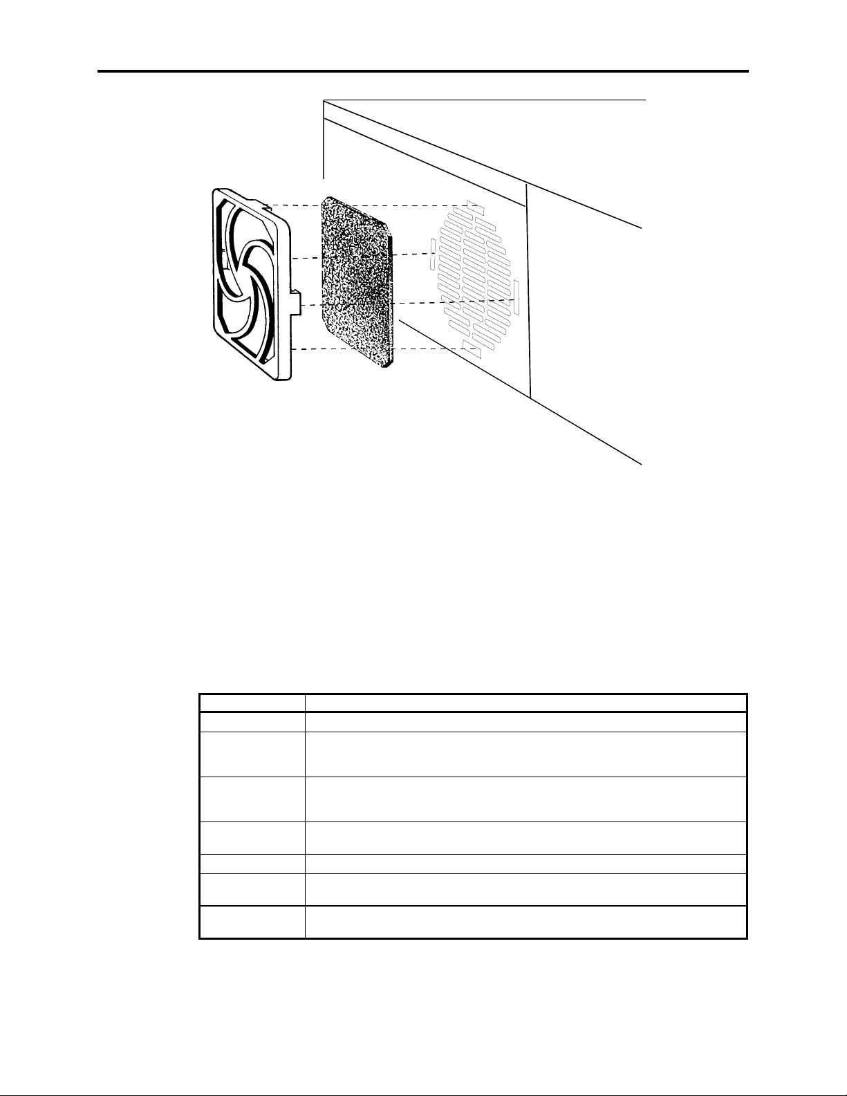
Chapter 6 – Maintenance
Figure Chapter 6 -1. Changing the Fan Filters
Chemical Compatibility
Certain combinations of chemical environments, temperature, and stress can adversely
affect parts made from thermoplastic resin. For this reason, material which may come in
contact with the 9457 unit should be carefully evaluated under end-use conditions for
compatibility. Also, follow the use and compatibility recommendations of the material
manufacturer. Table Chapter 6 -1 lists general chemical compatibility guidelines for the
9457.
Chemical Class Effects
Acids No effect under most common conditions of concentration and temperature.
Alcohols Generally compatible at low concentration and room temperature. Higher
Alkalis Generally compatible at low concentration and room temperature. Higher
Aliphatic
Hydrocarbons
Amines Surface crystallization and chemical attack. Avoid.
Aromatic
Hydrocarbons
Detergents and
Cleaners
concentrations and elevated temperatures result in etching and attack evidenced by
decomposition.
concentrations and elevated temperatures result in etching and attack evidenced by
decomposition.
Generally compatible
Partial solvents and severe stress cracking agents. Avoid.
Mild soap solutions are compatible. Strong alkaline materials should be avoided.
Table Chapter 6 -1. 9457 Chemical Compatibility
6-3
Page 66

9457 Industrial Computer
Chemical Class Effects
Esters Cause severe crystallization. Partial solvents. Avoid.
Greases and
Oils
Halogenated
Hydrocarbons
Ketones Causes severe crystallization and stress cracking. Partial solvents. Avoid.
Silicone Oil and
Greases
Pure petroleum types generally compatible. Many additives used with them are not
compatible.
Solvents. Avoid.
Generally compatible up to 85ºC (185º F). Some contain aromatic hydrocarbons which
should be avoided.
6-4
Page 67
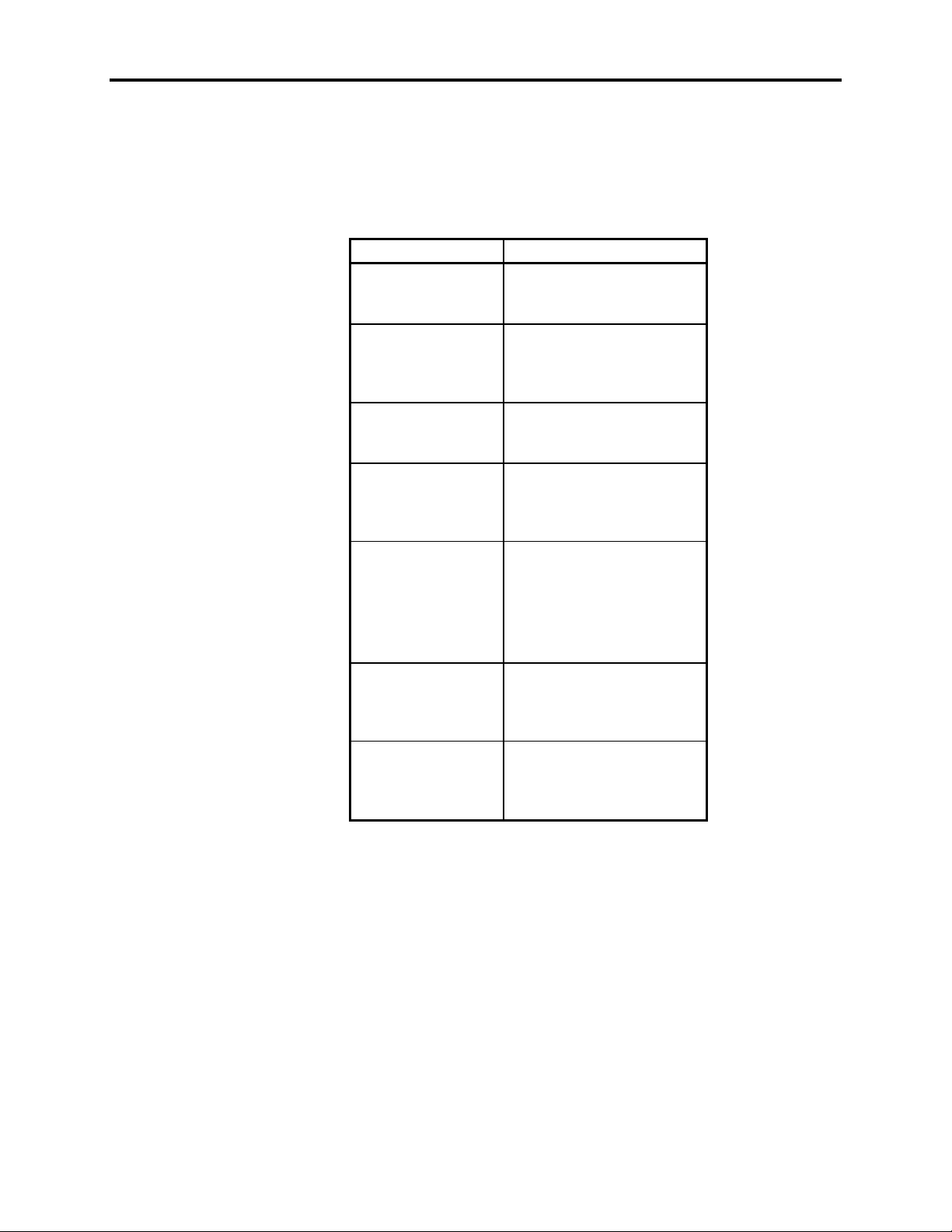
Compatible Lubricants
Table Chapter 6 -2 lists known compatible lubricants and the manufacturer’s names. If
you want to use a lubricant that is not listed, contact the appropriate manufacturer to determine if it is compatible.
Table Chapter 6 -2. 9457-Compatible Lubricants
Lubricants Manufacturer
DC® 230
Molykote® 33
Harmony® 68
Security® 68
Lubriplate®
Aero
Martemp® 2500 E.F. Houghton & Co.
Nyogel® 795A
Rheolube® 368
Rheolube® 723G
Rheolube® 788
Synthetic Oil® 181
SF® 1147
Versilube® F-50
Terrestic ® 77 Exxon
Dow Corning
Midland, MI 48640
(800) 248-2345
Gulf Oil
Petroleum Prod. Dept.
Pittsburgh, PA 15230
(412) 655-6247
Fisher Bros. Refinery
129 Lockwood Street
Newark, NJ 07105
303 W. Lehigh Ave.
Philadelphia, PA 19133
(215) 666-4000
Wm. J Nye
P.O. Box G-927
New Bedford, MA 02742
(617) 966-6721
GE
Silicone Products
Waterford, NY 12188
(518) 237-3330
P.O. Box 2180
Houston, TX 77092
(713) 680-5712
Chapter 6 – Maintenance
6-5
Page 68
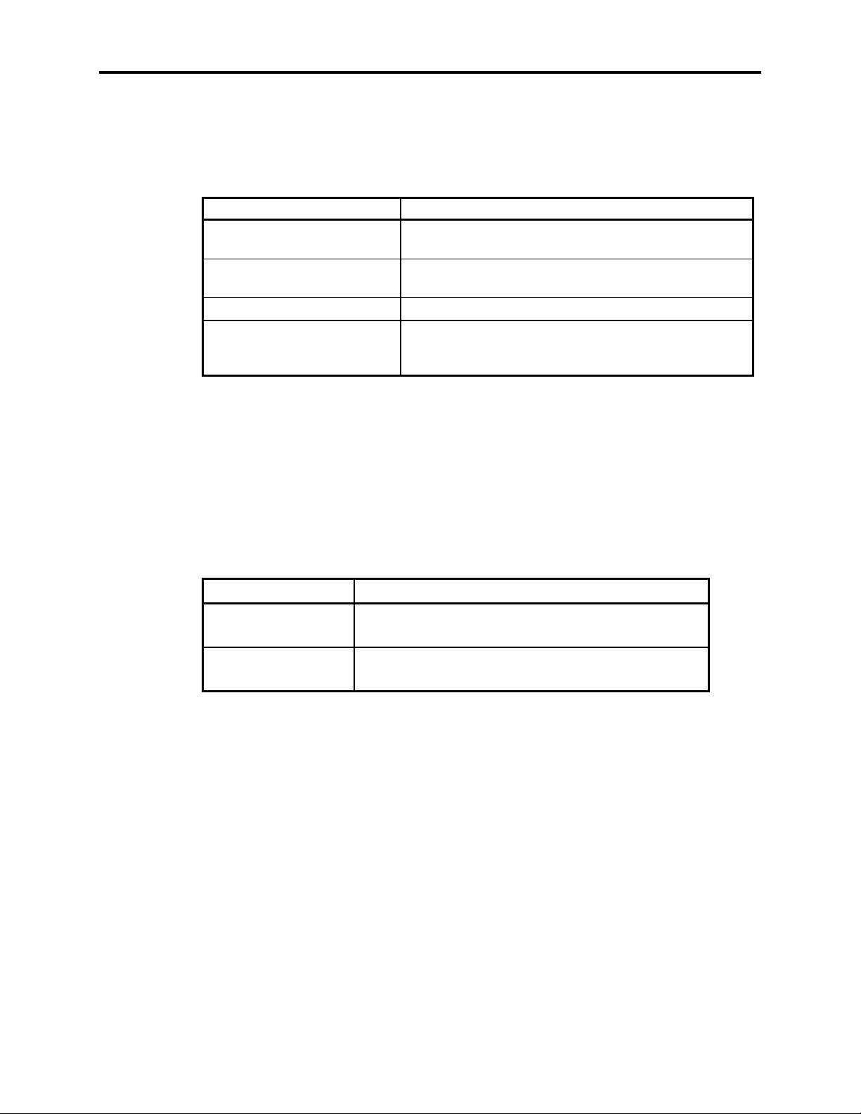
9457 Industrial Computer
Compatible Cleaning Agents
Table Chapter 6 -3 lists known compatible cleaning agents. If you want to use a cleaning
agent that is not listed, contact the appropriate manufacturer for compatibility.
Table Chapter 6 -3. 9457-Compatible Cleaning Agents
Type Agents
Aliphatics Hexane, Heptane, White Kerosene Mineral Spirits,
Alcohols Methyl, Isopropyl and Isobutyl, 1 + 3 Denatured
Halogenated Hydrocarbons Freons TF & TE
Detergents and Cleaners Mild Soap and Water Solution, VM&P Naphtha
The above aliphatics, alcohols, and halogenated hydrocarbons should be used only for
wiping or short-term immersion (less than 10 minutes). If parts are in complete immersion, care should be taken to remove all traces of solvent by forced-air drying or rinsing
in hot water.
Petroleum Ethers (65º C boiling point)
Alcohol
Fantastik®, Windex®, Joy®, Top Job®, Mr. Clean®,
Formula 409®
Non-compatible Cleaning Agents
The following cleaning agents are known to be detrimental to the 9457 unit.
Table Chapter 6 -4. 9457 Non-Compatible Cleaning Agents
Type Agents
Bases 25% Ammonium Hydroxide, 10% Potassium Hy-
droxide, Sodium Hydroxide
Organic Solvents Lacquer Thinner, Toluene, Methyl Cellosolve, Meth-
ylethylketone
6-6
Page 69
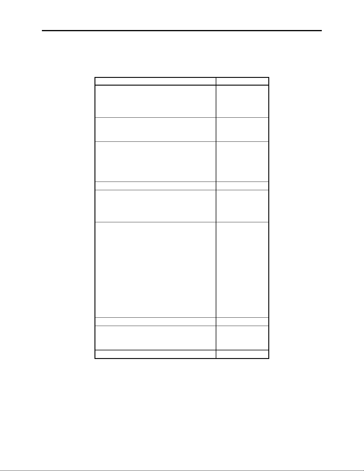
Spare Parts List
Use the part numbers in Table Chapter 6 -5 if you need to order parts for your 9457 unit:
Description Part Number
CPU
Hard Drive
Solid-State (Flash) Drive
Floppy Drive, 3.5", 1.44 Mbyte 109443-001
EDO DRAM for AT5+ CPUs
Host/LED Cable
Video Cable
Touch Screen/Mouse Cable
Monitor Power Cable
Remote Mount Kit 9457-RMK
19" Rack Filler panel
Front Floppy Kit 9457-FFK
Chapter 6 – Maintenance
Table Chapter 6 -5. 9457 Spare Parts
AT5+, 100 MHz, 0 Mbytes 101331-100
AT5+, 133 MHz, 0 Mbytes 101331-133
AT5+ Pentium, 200 MHz, 0 Mbytes 101331-200
850 Mbytes 109456-002
2.1 Gbytes 109456-004
10 Mbytes 109469-004
20 Mbytes 109469-001
40 Mbytes 109469-002
60 Mbytes 109469-003
1 Mbyte × 32 (4 Mbytes) 104273
2 Mbytes × 32 (8 Mbytes) 104258
4 Mbytes × 32 (16 Mbytes) 104302
24" 108085-001
72" 109859-001
18" 108114
72" 109861
18" 108098-001
72" 109874-001
18" 95536-001
72" 80318-001
Blank 9457-RFK
With Front Floppy Door Cutout 9457-RFC
6-7
Page 70

9457 Industrial Computer
Product Repair
Xycom’s Product Repair Department performs services to restore equipment to normal
operating condition and to implement authorized engineering changes which enhance
operating specifications. Products returned to Xycom will be tested using standard Xycom diagnostics. Contact the Product Repair Department for information on the turnaround time for the particular repair you require.
Preparing the Unit for Shipment
To ensure that the monitor is packed to minimize the chance of damage during shipment,
follow the steps described below before shipping.
1. Obtain an RMA number for your unit by calling your local Product Repair Department, or the Xycom Repair Center at 1-800-289-9266. Have the following information on hand when you call:
Your company’s name, and shipping and billing addresses
•
The type of service desired–product repair or product exchange
•
The product model number, part number, serial number, quantity, and warranty
•
status
A thorough description of the product failure and the circumstances that led up
•
to it
Purchase order or repair order number
•
2. To prepare the unit for shipment, make sure that all case panels are secured using all
screws.
3. To speed processing of your repair, attach a written description of the failure to the
unit.
4. Place the unit securely in its original packaging or an equivalent heavy-duty container.
5. Mark the RMA number on the outside of the shipping box, as well as on your purchase order.
6. Ship the unit to your local Xycom Repair Center.
6-8
Page 71
Appendix A – Specifications
Environmental Specifications
Table Appendix A -1. 9457 Environmental Specifications
Temperature
Operating
Non-operating
Humidity
Operating
Non-operating
Altitude
Operating
Non-operating
Shock*
Operating
Non-operating
Vibration*
Operating
Non-operating
0° to 50° C (32° to 122° F)
-40° to 60° C (-40° to 140° F)
20% to 80% RH, non-condensing
20% to 90% RH, non-condensing
Sea level to 10,000 ft. (3048 m)
Sea level to 40,000 ft. (12192 m)
15 g peak acceleration (11 msec duration)
20 g peak acceleration (11 msec duration)
5 to 2,000 Hz
.006" (.15mm) peak-to-peak displacement
1.0 g (maximum) acceleration
5 to 2,000 Hz
.015" (.38mm) peak-to-peak displacement
2.5 g (maximum) acceleration
*Note
The shock and vibration specifications require that the solid state disk drive be installed. Also, CD-ROM and standard hard disk drives should
be used in applica-
not
tions where high levels of shock and vibration are present.
If a CD-ROM drive is installed, the shock and vibration specifications of this unit are
limited to the shock and vibration specifications of the CD-ROM drive.
Note
Operating temperatures above 40° C (104° F) may adversely affect the purity of the
colors displayed on the monitor.
A-1
Page 72
9457 Industrial Computer
Hardware Specifications
Table Appendix A -2. 9457 Hardware Specifications
9457 Computer Module
Mechanical
Height
Width
Depth
Weight
Electrical 115/230 VAC, auto-switching, 6.3 A, 50/60 Hz, 200 watts
Passive Backplane 2 PCI and 5 PC/AT ISA slots (2 PCI, 4 ISA available to user)
Mounting Under monitor module, or remote mounting
5.9" (149.9 mm)
16.0" (406.4 mm)
15.6" (396.25 mm)
30.0 lbs. (66.3 kg)
125 watts available to backplane and drives
+5 VDC @ 16.9 A/+12 VDC @ 7.0 A
-5 VDC @ 0.5 A/ -12 VDC @ 0.48 A
Not to exceed 125 Watts, total.
9457 Monitor Module
Mechanical
Height
Width
Mounting Depth
Depth
Weight
Electrical 110-240 VAC, auto-sensing, 50/60 Hz
Mounting EIA standard panel mounting
15.72" (399.29 mm), “9U”
17.38" (441.45 mm), main body
19.0" (482.6 mm), across front panel
17.5" (444.5 mm)
18.5" (469.9 mm)
61.0 lbs. (134.81 kg)
A-2
Page 73

9457 Computer and Monitor Modules (Combined)
Mechanical
Height
Width
Mounting Depth
Depth
Weight
Electrical 115/230 VAC, auto-switching, 50/60 Hz
Mounting EIA standard panel mounting
Default Video Modes
The 9457 monitor module supports all display modes up to 1280 × 1024 at 60 Hz,
non-interlaced, including most common video formats using a horizontal scan rate from
15 to 64 KHz and a vertical scan rate from 45 to 125 Hz. In almost all cases, the monitor
will adjust to the incoming video signal automatically.
Appendix A – Specifications
19.92" (505.97 mm), behind mounting panel
17.38" (441.45 mm), main body
19.0" (482.6 mm), across front panel
17.5" (444.5 mm)
18.5" (469.9 mm), overall
91.0 lbs. (198.9 kg)
The most common formats are as follows:
Table Appendix A -3. 9457 Monitor Module Default Video Modes
HF VF
Resolution (KHz) (Hz) Interlacing
640 × 350 31.46 70.08 Non-Interlaced
640 × 400 31.46 70.08 Non-Interlaced
640 × 480 25.18 59.94 Non-Interlaced
800 × 600 48.08 72.19 Non-Interlaced
1024 × 768 60.02 75.03 Non-Interlaced
1280 × 1024 64.310 60.00 Non-Interlaced
For instructions on setting the monitor to support other modes, refer to
Monitor
, in Chapter 4 of this manual.
Adjusting the
A-3
Page 74
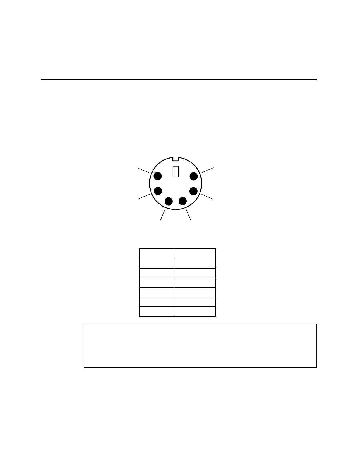
Appendix B – Pinouts
D
Keyboard Connectors
The 9457 has four standard PS/2-compatible keyboard connectors, one mounted on the
back panel of the computer module, one mounted on the front of the monitor module,
and two mounted on the back of the monitor module. For the specific locations, refer to
the figures in Chapter 1.
All four connectors are wired identically, as shown in Figure Appendix B -1.
NC
56
4
+5V
NC
Figure Appendix B -1. Keyboard Pinout Diagram
Table Appendix B -1. Keyboard Connector Pinout
Pin Signal
1DATA
2N/C
3GND
4+5 VDC
5CLK
6N/C
3
2
1
DATA
CLK
GN
Warning
Do not connect a keyboard to the keyboard port on the back of the 9457 computer
module if the computer module is connected to the monitor module using the
Host/LED cable. Doing so may cause the keyboard to function improperly.
You may connect a keyboard to the front or back keyboard port on the monitor module
when the Host/LED cable is connected between the monitor module and the computer
B-1
Page 75
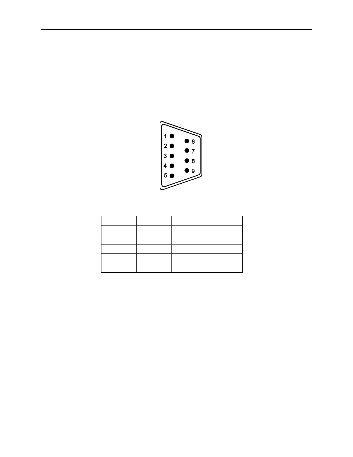
9457 Industrial Computer
module. Only connect a keyboard to the keyboard port on the computer module if the
computer and monitor modules are
Serial Ports
The 9457 uses standard nine-pin DB-9M (male) connectors to facilitate interface to
RS-232 compatible serial devices. These connectors are mounted on the rear panel of the
9457.
connected using the Host/LED cable.
not
Figure Appendix B -2. Serial Port Pinout Diagram
Table Appendix B -2. RS-232 (Serial Port) Connector Pinout
Pin Signal Pin Signal
1 DCD 6 DST
2RXD7RTS
3TXD8CTS
4DTR9RI
5GND
B-2
Page 76
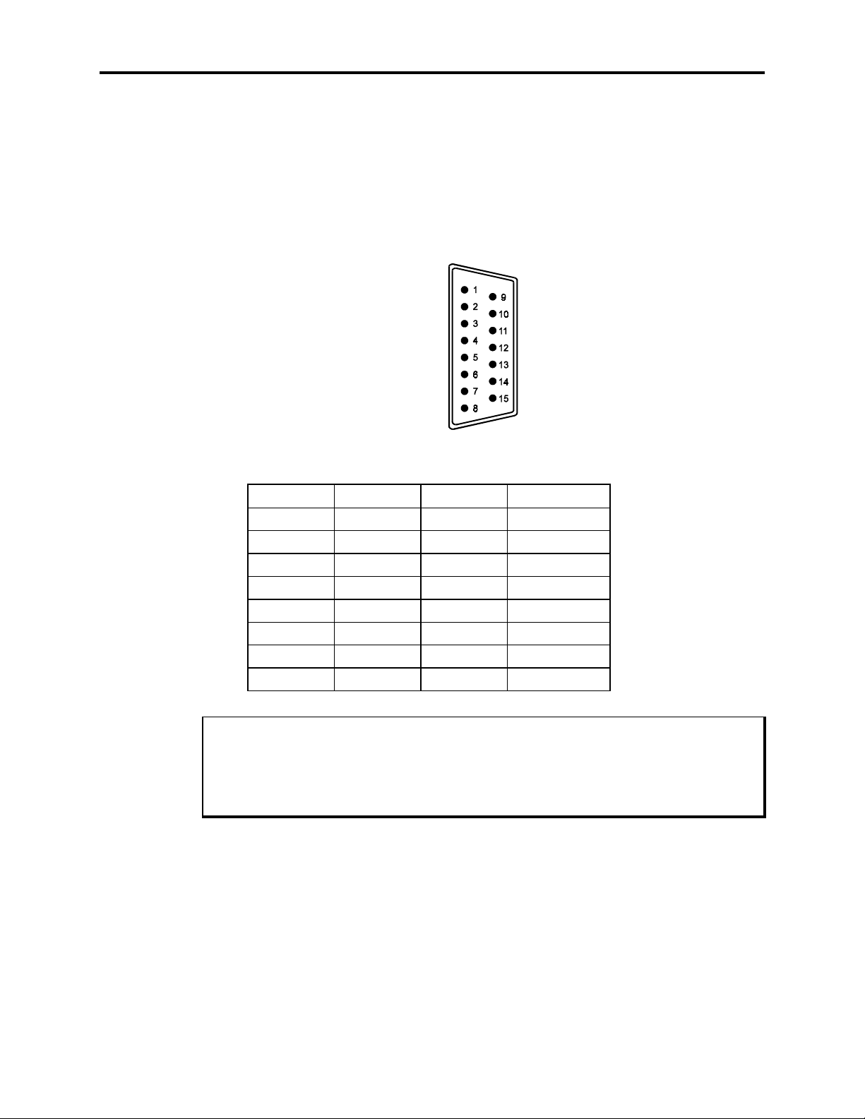
Host/LED Port
The monitor module may be connected to the computer module using a 15-pin cable
between the Host/LED connectors on both modules. This cable carries the keyboard signals to the computer module from the monitor module’s integrated keypads and any keyboard that is connected to the monitor module’s keyboard ports. This cable also carries
the signals used to light the system status LEDs on the front panel of the monitor module. This DB-15M (male) connector is mounted on the rear panel of the monitor module.
Appendix B – Pinouts
Figure Appendix B -3. Host/LED Port Pinout Diagram
Table Appendix B -3. Host/LED Port Connector Pinout (Monitor Module)
Pin Signal Pin Signal
1 +5 VDC 9 MAINT LED
2 +5 VDC 10 CLK
3 +5 VDC 11 FAULT LED
4 +5 VDC 12 COM LED
5 GND 13 DISK LED
6 GND 14 N/C
7 GND 15 DATA
8GND
Note
When connecting the monitor module to the computer module, use
Host/LED cable or a cable between the monitor module’s keyboard Out port and the
computer module’s Keyboard port (not included),
cause the keyboard to operate improperly.
but not both
either
the supplied
. Using both cables will
B-3
Page 77

9457 Industrial Computer
B-4
Page 78

Index
A
About this manual, 1-3
Adjusting the monitor, 4-3
Agency approvals, 1-12
Alpha keys, 1-7
B
Brightness knob, 1-10
C
CD-ROM drivers, installation, 3-16
CE marking, 1-12
Chemical compatibility, 6-3
cleaning agents
compatible, 6-5
non-compatible, 6-5
lubricants, compatible, 6-4
COM1, 1-6
COM2, 1-6
Computer module
carton, contents, 1-3
features, 1-1
front components, 1-4, 3-1
installing external hardware options, 3-11
installing internal components, 3-3
mounting to the monitor module, 3-21
rear components, 1-5, 3-2
removing from the monitor module, 3-22
Connectors
Host/LED, B-3
Keyboard, B-1
Serial, B-2
Contrast knob, 1-10
Cooling grille
computer module, 1-5
monitor module, 1-8
CPU board
installation, 3-5
removal, 3-6
CUL approval, 1-12
Degauss button, 1-10
Degaussing the monitor, 4-6
Derating the power supply, 3-23
diagnostic programs, 2-1
Download Menu, PKIM utility, 5-8
drivers
CD-ROM, 3-16
miscellaneous, 3-16
mouse, 3-15
touch screen, 3-15
video, 3-15
E
Environmental specifications, A-1
Excessive heat, 3-18
Excessive line voltage, 3-18
Excessive noise, 3-18
External keyboard port, 1-7
F
Fan intake filters, 1-5
cleaning, 6-1
replacing, 6-2
FCC compliance, 1-12
Files menu, PKIM utility, 5-3
Floppy drive
front access door, installing, 3-8
front bay, 1-5
front floppy kit, installing, 3-6
Front drive bay, 1-5
function keys, 1-7
G
Grounding, 3-17
D
data entry keypad, 1-7
Index-1
Page 79

9457 Industrial Computer
H
Hardware specifications, A-2
Heat, excessive, 3-18
Host/LED connector
computer module, 1-6
monitor module, 1-9
I
Installation, 3-1, 3-19
CD-ROM drivers, 3-16
device in the 5.25" drive bay, 3-9
external hardware options, 3-11
internal hardware options, 3-4
keyboard cable clamps, 3-13
miscellaneous drivers, 3-16
mouse drivers, 3-15
operating systems, 3-15
panel, 3-19
PC boards, 3-6
quick start-up, 1-10
Remote Mount Kit, 3-11
system mounting considerations, 3-16
touch screen drivers, 3-15
video drivers, 3-15
ISO 9001 certification, 1-12
K
Keyboard, 1-8
installing cable clamps, 3-12
ports, 1-5, 1-8, 1-9
Keypad Utility Program. See Programmable Keypad
Utility Program
Keypads
configurations, 1-2
data entry, 1-7
using, 4-1
L
LEDs, status, 1-8, 4-2
line voltage, excessive, 3-18
M
Macros Menu, PKIM utility, 5-4
Main Menu, 5-3
Maintenance, preventive, 6-1
Monitor auxiliary outlet, 1-5
Monitor module, 1-7
adjusting the monitor, 4-3
carton, contents, 1-3
degaussing the monitor, 4-6
Monitor module (continued)
features, 1-2
front panel components, 1-6
keypads, 1-2
rear components, 1-8
Mounting considerations, 3-16
Mouse, 1-8
installing drivers, 3-15
port, 1-9
using, 4-1
N
noise, excessive, 3-18
O
On/Off switch, 1-5
On-Screen Display mode
button, 1-10, 4-3
options, 4-3
operating systems, installation, 3-14
Optional items, 1-2
P
PC boards, installing, 3-6
Pinouts
Host/LED port, B-3
Keyboard connectors, B-1
Serial ports, B-2
PKIM utility. See Programmable Keypad Utility Program
(PKIM)
Ports
Host/LED, B-3
Keyboard, B-1
Serial, B-2
Power
available for expansion, 3-23
considerations, 3-16
excessive line voltage, 3-18
excessive noise, 3-18
grounding, 3-17
management, 4-5
receptacle, 1-5, 1-9
Power management modes, 4-5
Preparation
for testing, 2-2
for use, 3-4
unit for shipment, 6-7
Product overview, 1-1
Product repair, 6-7
Programmable Keypad Utility Program (PKIM), 5-1
Index-2
Page 80

Index
Q
Quick start-up, 1-10
R
Regulatory compliance, 1-12
Remote Mount Kit, 3-11
Removing the computer module, 3-22
Rep
air, 6-7
S
Serial loopback connections, 2-2
Serial ports, 1-6
Shock, A-1
Soak test button, 1-9
Spare parts list, 6-6
Specifications
Environmental, A-1
Hardware, A-2
Standard features, 1-1
Startup, PKIM utility, 5-2
Status LEDs, 1-8, 4-2
System Components, 1-4
System power, 3-17
system setup, checking, 2-1
T
Testing the 9457
checking system setup, 2-1
initiating the tests, 2-1
preparations for, 2-2
running the tests, 2-2
Touch screen
driver software, 1-11, 3-15
port, 1-9
U
UL approval, 1-12
Unit, preparing for shipment, 6-7
Unpacking the system, 1-3
Upload Menu, PKIM utility, 5-8
Utilities Menu, PKIM utility, 5-9
Utility Batch Mode, 5-2
V
Video controls, 1-10
brightness knob, 1-10
contrast knob, 1-10
degauss button, 1-10
On-Screen Display mode button, 1-10
soak test button, 1-10
Video drivers, installation, 3-15
Video input port, 1-9
Video modes, default, A-3
Index-3
 Loading...