


3500 3-Slot Manual
3510T/3510KP(T), 3512T/3512KP(T), 3535T/3535KPM(T) Flat-Panel Industrial PCs
2002 XYCOM AUTOMATION, INC. Printed in the United States of America


Revision Record
Revision Description Date
A Manual Released 5/99
B Updated Specifications 7/99
C Updated Bulb Replacement/CD-ROM Floppy addition 5/01
D Addition of 3535 Flat Panel Monitor PC 3/02
E Touchscreen Updates 7/02
Part Number 350003(E)
Trademark Information
Brand or product names are registered trademarks of their respective owners.
Windows is a registered trademark of Microsoft Corp. in the United States and other countries.
Copyright Information
This document is copyrighted by Xycom Automation Incorporated (Xycom Automation) and shall not be reproduced
or copied without expressed written authorization from Xycom Automation.
The information contained within this document is subject to change without notice. Xycom Automation does not
guarantee the accuracy of the information.
United States FCC Part 15, Subpart B, Class A EMI Compliance Statement:
NOTE: This equipment has been tested and found to comply with the limits for a Class A digital device, pursuant to
part 15 of the FCC Rules. These limits are designed to provide reasonable protection against harmful interference
when the equipment is operated in a commercial environment. This equipment generates, uses, and can radiate
radio frequency energy and, if not installed and used in accordance with the instruction manual, may cause harmful
interference to radio communications. Operation of this equipment in a residential area is likely to cause harmful
interference in which case the user will be required to correct the interference at his own expense.
For European Users - WARNING:
This is a Class A product. In a domestic environment this product may cause radio interference in which case the
user may be required to take adequate measures.
INSTALLATION: Electromagnetic Compatibility WARNING:
The connection of non-shielded equipment interface cables to this equipment will invalidate FCC EMI and European
Union EMC compliance and may result in electromagnetic interference and/or susceptibility levels which are in
violation of regulations applying to the legal operation of this device. It is the responsibility of the system integrator
and/or user to apply the following directions relating to installation and configuration:
All interface cables must include shielded cables. Braid/foil type shields are recommended. Communication cable
connectors must be metal, ideally zinc die-cast backshell types, and provide 360 degree protection about the
interface wires. The cable shield braid must be terminated directly to the metal connector shell, ground drain wires
alone are not adequate.
Protective measures for power and interface cables as described within this manual must be applied. Do not leave
cables connected to unused interfaces or disconnected at one end. Changes or modifications to this device not
expressly approved by the manufacturer could void the user’s authority to operate the equipment.
EMC compliance is, in part, a function of PCB design. Third party add-on AT/XT peripheral PCB assemblies installed
within this apparatus may void EMC compliance. FCC/CE compliant PCB assemblies should always be used where
possible. XYCOM AUTOMATION can accept no responsibility for the EMC performance of this apparatus after
system integrator/user installation of PCB assemblies not manufactured and/or expressly tested and approved for
compliance by XYCOM AUTOMATION. It is the responsibility of the system integrator/user to ensure that installation
and operation of such devices does not void EMC compliance.
3


Table of Contents
CHAPTER 1 - INTRODUCTION..............................................................................................................................9
P
RODUCT OVERVIEW..................................................................................................................................................9
Standard Features.................................................................................................................................................9
Optional Features (All Units)..............................................................................................................................11
U
NPACKING THE SYSTEM .........................................................................................................................................11
Q
UICK START-UP......................................................................................................................................................12
CHAPTER 2 - TESTING..........................................................................................................................................13
P
REPARING FOR THE TESTS ......................................................................................................................................13
R
UNNING THE TESTS ................................................................................................................................................15
CHAPTER 3 – INSTALLATION............................................................................................................................17
F
RONT PANEL...........................................................................................................................................................17
3510T/12T Front Panel.......................................................................................................................................17
3510KP/3512KP and 3510KPT/3512KPT Front Panel......................................................................................19
3535T Front Panel ..............................................................................................................................................21
3535KPM(T) Front Panel....................................................................................................................................22
I/O Panel 3510/1512 ...........................................................................................................................................23
I/O Panel 3535 ....................................................................................................................................................23
Back Panel...........................................................................................................................................................25
Power Panel ........................................................................................................................................................27
Preparing the System...........................................................................................................................................27
I
NSTALLING INTERNAL HARDWARE OPTIONS ...........................................................................................................28
DRAM and Additional DRAM Single In-line Memory Modules (SIMMs)...........................................................28
PC/AT and PCI Boards.......................................................................................................................................28
I
NSTALLING EXTERNAL HARDWARE OPTIONS ..........................................................................................................29
9000-EXF External Floppy Drive .......................................................................................................................29
9000-FFK External Front Floppy and Keyboard Access Kit..............................................................................29
9000-CDK External Front Access CD-ROM and Keyboard Kit.........................................................................31
C
USTOM LOGO .........................................................................................................................................................34
C
REATING CUSTOM KEYPAD INSERTS (FOR 3510/3512KP UNITS)...........................................................................35
R
EINSTALLING OPERATING SYSTEMS .......................................................................................................................39
MS-DOS
Windows
Windows
Windows NT
Windows
I
NSTALLING DRIVERS ...............................................................................................................................................41
reinstallation.....................................................................................................................................39
95 reinstallation................................................................................................................................40
98 reinstallation................................................................................................................................40
reinstallation...............................................................................................................................40
2000 reinstallation............................................................................................................................41
Ethernet Drivers..................................................................................................................................................41
Video Expansion..................................................................................................................................................42
Touchscreen Drivers............................................................................................................................................44
Miscellaneous Drivers.........................................................................................................................................44
U
SING A TOUCHSCREEN ........................................................................................................................................... 45
Calibrating the Touchscreen ...............................................................................................................................47
I
NSTALLING THE SYSTEM INTO A PANEL ...................................................................................................................48
Mounting Considerations....................................................................................................................................48
S
YSTEM POWER........................................................................................................................................................49
E
XCESSIVE HEAT......................................................................................................................................................49
E
LECTRICAL NOISE...................................................................................................................................................49
L
INE VOLTAGE VARIATION.......................................................................................................................................51
C
REATING A POWER CABLE......................................................................................................................................51
AC Power Cable..................................................................................................................................................51
DC Power Cable..................................................................................................................................................52
5

3500 Flat Panel Industrial PCs
OUNTING THE UNIT ...............................................................................................................................................53
M
System Cutout Dimensions .................................................................................................................................. 54
P
OWER SUPPLY ............................................................................................................................... .........................56
H
AZARDOUS LOCATIONS INSTALLATIONS ................................................................................................................ 57
S
AFETY AGENCY APPROVAL ....................................................................................................................................57
Definitions ...........................................................................................................................................................59
Class I Locations.................................................................................................................................................59
Class II Locations................................................................................................................................................59
Division 1 Locations............................................................................................................................................59
Division 2 Locations............................................................................................................................................60
Hazardous Locations Group Ratings..................................................................................................................60
E
NCLOSURES ............................................................................................................................................................60
P
OWER SWITCH ........................................................................................................................................................61
C
ABLE CONNECTIONS...............................................................................................................................................61
Communication Cable Interface..........................................................................................................................61
O
PERATION AND MAINTENANCE ..............................................................................................................................62
CHAPTER 4 - KEYPAD UTILITY FOR 3510KP/3512KPM...............................................................................63
L
OADING THE KEYPAD UTILITY................................................................................................................................63
U
SING THE KEYPAD UTILITY....................................................................................................................................63
CHAPTER 5 - KEYPAD UTILITY FOR THE 3535 KPM...................................................................................7 3
CHAPTER 6 - MAINTENANCE.............................................................................................................................81
P
REVENTIVE MAINTENANCE ....................................................................................................................................81
M
AINTENANCE .........................................................................................................................................................82
Fuse Replacement................................................................................................................................................82
Fan Filter Replacement.......................................................................................................................................82
C
HEMICAL COMPATIBILITY.......................................................................................................................................83
Compatible Lubricants........................................................................................................................................84
Compatible Cleaning Agents...............................................................................................................................85
Non-compatible Cleaning Agents........................................................................................................................86
3510/3512/3510KP/3512KP/3535KPM/3535T S
P
RODUCT REPAIR PROGRAM/RETURNING A UNIT TO XYCOM AUTOMATION............................................................87
PARE PARTS LIST ........................................................................86
APPENDIX A – TECHNICAL SPECIFICATIONS..............................................................................................89
H
ARDWARE SPECIFICATIONS ....................................................................................................................................89
APPENDIX B - BLOCK DIAGRAM .....................................................................................................................91
APPENDIX C - PINOUTS.......................................................................................................................................93
KEYBOARD PORT CONNECTORS...............................................................................................................................93
A
UX PORT CONNECTOR............................................................................................................................................93
D
UAL USB CONNECTOR (USB1).............................................................................................................................94
P
ARALLEL PORT CONNECTOR (LPT1)......................................................................................................................94
S
ERIAL PORT CONNECTORS......................................................................................................................................94
COM1......................................................................................................................................................................95
COM2......................................................................................................................................................................95
VGA C
E
ONNECTOR....................................................................................................................................................96
XTERNAL FLOPPY CONNECTOR ..............................................................................................................................96
APPENDIX D – REPLACING FLAT PANEL DISPLAY BULBS.......................................................................97
3510 U
NITS ..............................................................................................................................................................97
Mitsubishi TFT Flat panel Display (model #AA104VB02)..................................................................................97
3512
AND 3512 KP UNITS........................................................................................................................................99
6

Table of Contents
Mitsubishi TFT Flat panel Display (Model #AA121SK12) .................................................................................99
I
NDEX.....................................................................................................................................................................103
7


Chapter 1 - Introduction
Product Overview
The 3500 series Flat-Panel Industrial Computers combine an Intel Celeron or
Pentium III processor with a flat-panel display to offer a powerful, compact
package for the factory floor and other harsh environments. The PC features an open
architecture to meet a wide variety of applications that require both a powerful PC
and a durable industrial enclosure.
The 3500 systems include:
• A three-slot ISA/PCI backplane which accommodates ¾ length expansion cards
• Flat panel displays
• 3510 – 10.4” – 640x480 VGA (TFT)
• 3512 – 12.1” – 800x600 SVGA (TFT)
Chapter One - Introduction
• 3535 – 15” – 1024x768 XGA (TFT)
• Touchscreen versions 3510T/3512T/3535T
• Keypad version (3510KP/3512KP/3535KPM)
• Keypad and touchscreen units (3510KPT/3512KPT/3535KPMT)
• Hard disk drive facilities
The front panel of the unit is sealed to NEMA 4/4X/12 and IP65 standards, and is
protected by an impact-resistant shield.
The system’s modular design allows easy access to expansion boards, switches,
power supply, flat-panel display, and disk drives.
Standard Features
The 3500 3-slot series ships standard with the following:
• Intel Celeron or Pentium III processor
• Up to 512 MB DRAM
• 10 GB hard drive
• 2 Serial ports
• 1 RS-232 or RS-485 port
• 1 Dedicated RS-232
• Reprogrammable keypad or analog resistive touchscreen, or both for operator input
• Two USB ports
9

3500 Flat Panel Industrial PCs
• IP65 standard
• UL listed for hazardous locations: Class I, Division 2
• Power supply
• MS-DOS operating system
• Flash BIOS
• 5.75” mounting depth (6.5” with external floppy option, 7.16” with external CD-
ROM/floppy drive option)
• External floppy connector
• Flat-panel display
• 10.4” TFT (640x480) (3510)
• 12.1” TFT (800x600) (3512)
• Three AT bus ¾ length expansion slots
• One ISA slots
• One PCI slot
• One ISA/PCI slot
• IR Port (IrDA, HPSIR, AND ASKIR compatible)
• Rear PS/2 keyboard port and mouse port (also front PS/2 keyboard port on 3510KP
and 3512KP)
• Keypads (3510KP/3512KP)
• 32 relegendable function keys (64 with the F/A function)
• Keypad (3535KPM)
• 74-position keypad and industrial mouse (touchscreen option)
• 40 relegendable keys (80 with F/A key)
• Status LEDs
• Power
• Disk
• Com
• Input
• External floppy and CD-ROM option, side access
• MS-DOS
Windows 95, Windows 98, Windows NT or Windows 2000
• Front panel sealed to meet NEMA 4/4X/12 and IP65 specifications when panel
mounted
• Status LEDs
10

• Power
• Disk
• Com
• Input
Optional Features (All Units)
Following are optional available features:
• Faster processor speeds
• Touchscreen-resistive technology with less than 1.5% linearity error
• Preinstalled Windows 95, Windows 98, Windows 2000 or Windows NT
• 9000-EXF, hot installable external floppy drive
• 9000-RF1 19-inch Rack Mount Adapter Plate (3510, 3512)
• 9000-FFK, NEMA 4 Front Floppy Kit
Chapter One - Introduction
• 9000-RFC 19-inch Floppy Door Plate
• 2005-RMA 19 inch Rack Mount Adapter Plate (3510KP, 3512KP)
• 9000-CDK, NEMA 4 front Access CD-ROM and keyboard kit
Unpacking the System
When you remove the system from its box, verify that you have the parts listed
below. Save the box and inner wrapping in the event you need to reship the unit.
• 3510T/3512T/3535T or Keypad version
• Documentation kit, which includes:
• Power connector
• Diagnostic software diskette
• 14 10-32 hex nuts (2 spares)
• Clip-on Ferrite for mouse cables
• Cable clamp and screw (for strain relief of power cord)
• 3510/3512/3535 manual
• CPU manual (CD-ROM)
• Utility diskettes
If you ordered the system with a touchscreen installed, you will also receive a
touchscreen driver diskette and a documentation CD that includes the manual.
11

3500 Flat Panel Industrial PCs
Quick Start-up
This section gives you the steps to get the system up and running without explaining
the capabilities and options.
Turn off power to the unit and disconnect the power cord before making any
adjustments to the inside or outside of the computer.
To prepare the system for use, perform the following steps.
1. Attach optional keyboard to the keyboard port.
2. Attach other optional equipment following the instructions in Chapter 3.
3. Attach the power cord from the power receptacle to a properly grounded 115/230
VAC, 50-60 Hz outlet, or 24 VDC outlet, whichever applies. (See Chapter 3,
Creating a Power Cable.)
4. Turn on the power to the unit. The system will boot up into the operating system.
Warning
5. Install application software via the external floppy, the network, or the IR port.
12

Chapter 2 - Testing
On units with MS-DOS, Xycom Automation provides diagnostic tests to verify the
operation of the system hardware functions. If any of these tests fail, either you do
not have the correct default setting or there is a failure. Check the default settings
and run the tests again. If another failure occurs, contact Xycom Automation’s
Product Repair & Customization Department (see Chapter 5).
Remove device drivers and memory resident programs (TSRs) that are installed on the
system before running Xycom diagnostics. If this step is not completed unexpected
failures may occur.
Make sure the BIOS setup menus are configured properly (factory-set configuration).
To enter the BIOS setup menus:
• Press
• Make the necessary changes by following directions on the screen.
• Press ESC
• Press ENTER twice to save the settings and exit.
Refer to the CPU manual for more information on the Setup Menu.
F2 after the POST RAM test has completed.
.
Chapter Two - Testing
Note
Preparing for the Tests
To test your system, you need the following equipment:
• Floppy disk drive
• IBM PC/AT or PS/2-compatible
• Xycom System Test Disk 3.5 inch, DS/DD disk (bootable), Xycom part number
99290-001
• Centronics-compatible printer cable
• Parallel printer (Centronics-style interface)
• Two serial loopback test connectors (refer to Figure 2- 1 for pinouts)
• Formatted 3.5-inch, DS/HD (1.44 Mbyte) disk
13

3500 Flat Panel Industrial PCs
Perform the following steps before starting the system tests:
1. Place the CPU board jumpers and switches to the factory set positions. Refer to
the CPU manual for these settings.
2. Plug the female end of the AC power cable into the side of the unit and the male
end into a properly grounded outlet.
3. Connect the serial loopback connector(s) and the printer cable to the appropriate
connectors, and connect a PC/AT or PS/2 keyboard. Figure 2-1, Serial Loopback
Connections, illustrates the wiring necessary for the loopback connection.
4. Default the CMOS setup to the factory settings.
14
Figure 2- 1. Serial Loopback Connections

Running the Tests
To run the test, insert the diagnostics disk into drive A. Turn on the computer (the
diagnostics program will boot-up). Figure 2- 2 shows the Main Menu.
Chapter Two - Testing
Copyright 1990-1998, Xycom, Inc. All rights reserved.
Diagnostic Tests Sequence/Selection Menu (Rel. xx)
1. WILL pause on error
2. SINGLE PASS test mode
3. Save setup to file
4. Extract setup from a file
A) RAM Test
B) Video RAM Test
C) Extended RAM Test
D) Real Time Clock Test
E) COM1 Serial Port Test
F) COM2 Serial Port Test
G) COM3 Serial Port Test
H) COM4 Serial Port Test
I) Math Coprocessor Test
J) Video Adjustments Test
[ENTER]=START TESTING
Use the letters to move the cursor and select/deselect, or use the arrow keys to move,
then use the [SPACE] key to select/deselect a test or function.
Figure 2- 2. Main Menu
5. Auto-select tests
6. Deselect all tests
7. Quit and exit to DOS
8. Return to previous screen
K) Video Interface Test
L) Speaker Port Test
M) LPT1: Printer Port Test
N) LPT2: Printer Port Test
O) C: Hard Drive Interface Test
P) D: Hard Drive Interface Test
Q) A: Floppy Drive Interface Test
R) B: Floppy Drive Interface Test
S) Keyboard, Keypad Tests
≡ = Test Selected
Note
Please read the DIAG.TXT file on the diagnostics disk for detailed information about
the tests.
Note
Avoid repeated running of any hard disk diagnostic utility if you use the Solid State
(Flash) drive option. The Flash drive has a limited number of writes to each logical
sector. Repeated writes from a diagnostic utility will prematurely shorten the life of the
drive.
15


Chapter 3 – Installation
This chapter illustrates the installation of, and the options for, the 3500. The figures
on the next several pages show the internal and external components on the front and
back panels of the unit to help you locate features relevant to installation.
Front Panel
The 3500 series has a NEMA 4/4X/12 and IP65 sealed front panel. The panel
protects the system’s interior when the system is properly panel mounted.
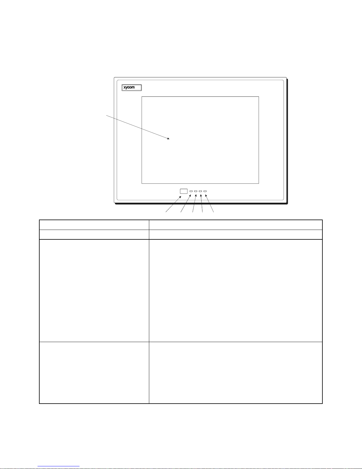
3510T/12T Front Panel
Chapter Three - Installation
Figure 3-1. 3510T/3512T Front Panel
17

3500 Flat Panel Industrial PCs
Feature Description
Display The 3510 has a 10.4-inch TFT Active Matrix Color LCD flat panel. Impact-
resistant shield protects the display from breakage. The 3512 has a 12.1”
TFT Active Matrix Color LCD flat panel. An impact-resistant shield
protects the display from breakage. If a touchscreen is factory installed, it
is backed by heat-annealed safety glass replacing the impact-resistant
shield.
Diagnostic LEDs Following is a description of the LEDs and what it means when they're lit:
Power Lit when the system has power
Disk Lit when the computer is accessing the disk drive
COM Lit when there is communication activity on one of the serial
ports, including communication between the computer module
and the touchscreen (if on COM2) or a serial mouse.
Input Lit when the unit has a touchscreen (LED gets brighter when a
touch input is detected) or a key is pressed
During power-up, firmware on the processor board checks the hardware
configuration against the configuration stored in the CMOS memory.
IR (Infrared) The IR port transceiver is located behind this window. The IR port is IrDA
and ASKIR compliant. Connect the unit to any IrDA compatible device.
Load special software (not included) to use this feature. The infrared (IR)
link is designed to operate at a distance of 0 to 1 meter. Enable the
interface through the BIOS setup menu. Note: When the IR port is
chosen in the system BIOS, COM2 is not available.
Keyboard Port Access
(Optional front access)
The 3510/3512 supports one PS/2 keyboard. Front access options are
available with the use of the 9000-FKA Front floppy/keyboard access kit
(not shown). The access is a PS/2 stacked mini-din located on the side of
the unit. Warning: To maintain safe conditions, do not use an external
keyboard and/or mouse port when the unit is operating in a hazardous
environment.
Floppy Disk Drive (Optional) The 3510/3512 has front access options available. (Refer to the External
Floppy Option section within this chapter.)
18

Chapter Three - Installation
3510KP/3512KP and 3510KPT/3512KPT Front Panel
The 3510KP and 3512KP have NEMA/4/4X/12 sealed front panels. The panel
protects the system’s interior when the system is properly panel mounted. Figure 3-2
illustrates the front panel with keypad.
Figure 3-2. 3510KP/12KP Front Panel
Feature Description
Display The 3510KP/3512KP has a 10.4-inch (640 x 420) TFT flat panel
display or a 12.1-inch SVGA (800 x 600) TFT flat panel display.
Diagnostic LEDs The 3510KP/3512KP features status LEDs on the front panel,
which allows monitoring of the system operation. Following is a
description of the LEDs and what it means when they're lit:
Power Lit when the system has power
Disk Lit when the computer is accessing the disk drive
COM Lit when there is communication activity on one of
the serial ports, including communication between
the computer module and the touchscreen (if on
COM2) or a serial mouse.
Input Lit when the unit has a touchscreen; the LED gets
brighter when a touch input is detected or a key is
pressed.
F/A key Indicates the keypads are in alpha mode
Function and User-Defined Keys These 32 relegendable function keys (64 using the F/A keys)
provide easy access to familiar routines. (F/A keys can be used
for alpha and symbol entry). See the Customizing Keypad
Inserts section in this chapter for details on customizing your
keypad inserts.
Numeric/Cursor Control Keypad Use the data entry keypad to enter data and move the cursor.
19

3500 Flat Panel Industrial PCs
Feature Description
PF10 Key (Keypad Configuration Key) This key reconfigures your keypad.
Keyboard Port (3510KP/3512KP)
(front access)
The 3510KP/3512KP provides both front and rear accessible
PS/2 keyboard connectors. The front accessible connector is
located on the lower right side of the front panel. The rear
accessible connector is located on the side of the unit.
Note: Only one keyboard port on the 3510/3512KP can be used
at a time.
Note: The installation of the touchscreen driver determines
whether a second pointing device will function correctly. If using
a mouse with a touchscreen, please review the Touchscreen
Driver Installation instructions.
20
3535T Front Panel
TOUCH
SCREEN
(OPT IONAL )
IR PORT
Chapter Three - Installation
POWER DISK COM INPUT
IR PORT POWER DISK
COM
INPUT
Feature Description
Display The 3535T has a 15-inch (1024 x 768) XGA flat panel display.
Diagnostics LED The 3535T features four status LEDs on the front panel, which
you can use to monitor system operation.
Power There is power to the 3535.
Disk The computer module is accessing the disk drive.
COM There is communication activity on one of the
computer module’s serial ports, including
communication between the computer module and the
touchscreen (if on COM2) or a serial device.
Input The unit has a touchscreen and the LED gets brighter
when touch input is detected.
During power-up, firmware on the processor board checks the
hardware configuration against the configuration stored in the
CMOS memory.
IR (Infrared) The IR port transceiver is loc ated behind this window. The
3535 IR port is IrDA, and ASK-IR compliant. You can connec t
the 3535 to any IrDA compatible device, if you load special
software (not included). The infr ar ed (IR) link oper ates at a
distance of 0 to 1 meter and is capable of 115 Kbaud transfer
rates. Enable the interface through the BIOS setup menus.
Note: When the IR port is chosen, COM2 is not available.
Correspondingly, if COM2 is in use by the touchscreen the IR is not
operational.
21

3500 Flat Panel Industrial PCs
3535KPM(T) Front Panel
Flat Panel Display
Programmable
Fun cti on K eys
Configuration
Key
Keyboar d Input
Funct ion Keys
IR DA PORT
Industrial Mouse
Programmable
Funct i on Keys
F/A Key
Windows Keys
Numeric Keypad
Cursor Control
System
Status LED
(Power)
System
Statu s LE D
(Input)
COM
DISK
Feature Description
Display The 3535KPM(T) TFT flat panel impact-resistant shield protects the display from
breakage. If a touchscreen is factory installed, the touchscreen is backed by heatannealed safety glass replacing the impact-resistant shield.
System Status LEDs The 3535 features four status LEDs on the front panel, which you can use to
monitor system operation.
Power There is power to the 3535.
Disk The computer module is accessing the disk drive.
COM There is communication activity on one of the computer module’s serial
ports, including communication between the computer module and the
touchscreen (if on COM2) or a serial device.
Input The unit has a touchscreen and the LED gets brighter when touch input
is detected.
During power-up, firmware on the processor board checks the hardware
configuration against the configuration stored in the CMOS memory.
IR (Infrared) The IR port transceiver is loc ated behind this window. The 3535 IR por t is Ir DA,
and ASK-IR compliant. You can connect the 3515 to any IrDA compatible
device, if you load special software (not included). T he inf r ared ( IR) link
operates at a distance of 0 to 1 m eter and is c apable of 115 Kbaud trans f er
rates. Enable the interface through the BIOS setup menus.
port is chosen, COM2 is not available. Correspondingly, if COM2 is in use by the
touchscreen the IR is not operational.
Note: When the IR
22

I/O Panel 3510/1512
(3)
)
EXPANSION SLOTS (3)
LID
ETHERNET
PORT
LID
REMOVAL
SCREW (2)
MOUNTING
STUD (12)
COM 2
RS-232
COM 1
RS-485
Chapter Three - Installation
MOUSE
VIDEO
FRONT PANEL
I/O Panel 3535
EXPANSION SLOTS
LID
ETHERNET
PORT
LID
REMOVAL
SCREW (2)
MOUNTING
STUD (12)
PARALLEL RS-232
KEYBD
Figure 3-3. System I/O 3510/1512Panel
COM 2
RS-232
COM 1
RS-485
MOUSE
USB PORT (2 )
VIDEO
FRONT PANEL
PARALLEL
RS-232
KEYBD
Figure 3-4 System 3535 I/O Panel
USB PORT (2
23

3500 Flat Panel Industrial PCs
Feature Description
Parallel Port The parallel printer port (LPT1) is a DB-25 pin female connector. This port provides a
standard PC compatible printer interface. An external push-button reset option is
available. Consult the CPU board manual for the jumper that controls this option.
COM Ports COM1 is RS-232/485 compatible. RS/232 is connected to the lower nine-pin stacked
DB connector. The top part of this stack is the RS/485 version of the same port. Since
these connectors are attached to the same port, only one can be used at a time. COM2
is the male 25-pin DB connector. COM2 is dedicated to the IR port, the touchscreen
controller, or the 25-pin connector. Only one option can be used at a time.
Note: If you ordered Windows NT
, the driver is on disk and a copy of the driver file is
on the hard drive. This operating system only supports COM2. Therefore, the
touchscreen will be on COM2, and COM2 will not be available for other use.
Keyboard Port The keyboard port is a PS/2 stacked mini-din so a PC/AT keyboard can be attached at
either the front or side of the unit. The keyboard port on the side of the unit is the lower
connector. Do not use when in the presence of a hazardous environment. Note: You
cannot use both keyboard ports on the 3535 at the same time.
Mouse Port The mouse port is a PS/2 stacked mini-din that allows you to attach a mouse at the
side of the unit. If you receive a unit with a touchscreen, this port may be covered with
a label stating that the port is not functional as shipped. This is dependent upon the
operating system installed.
Note: If the unit has a touchscreen and MS-DOS, Windows
3.x or Windows 95, the
touchscreen is configured for the mouse port, making the mouse port unavailable.
Reconfigure the touchscreen for use on COM2 to make mouse port functional.
Warning: To maintain a safe condition, do not use an external keyboard and/or
mouse port when the unit is operating in a hazardous environment.
Video Port The video port is a 15-pin D-sub VGA connector at the side of the unit. This connector
supports any standard VGA connection. The video port is shipped disabled. This port is
active if an LCD flat panel is not connected. A jumper can be used to switch between
the VGA port and the LCD flat panel. To use both a video display on the video port and
the flat panel display, you must enable “Simultaneous Video” on the Advanced Menu in
the BIOS setup. Refer to the CPU manual for details.
USB Universal Serial Bus (not available with AHIP4+ CPU)
Ethernet Port
This port provides a 10BASE-T/100BASE-TX autosensing Ethernet connection.
(optional)
24

Back Panel
A
Chapter Three - Installation
Figure 3-4. System Back Panel with Optional Removable Floppy Drive
OPTIONAL
FLOPPY
DRIVE
MOUNTING
STUD (12)
FRONT PANEL
BACK PANEL
SCREWS
SCREWS
FRONT PANEL
TTAC HMENT SCREWS
LID SCREWS
LID
FAN
FILTER
BACK PANEL
LID REMOVAL
Figure 3-5. System Back Panel with Optional Pre-installed Non-removable Floppy Drive
25

3500 Flat Panel Industrial PCs
CD-ROM/Floppy Drive Covers
Mounting Screw
Figure 3-6. System Back Panel with Optional Pre-installed Non-removable CD-ROM/Floppy Drive
CD-ROM/Floppy Drive
Mounting Screws ( 4)
Back Panel
Feature Description
Fasteners There are two protruding screws (lid removal screws) along the
top of the back panel. Loosen these screws to remove the lid.
There are four screws located across the top and bottom of the
back panel. Loosen these screws (using a Phillip-head
screwdriver) to remove the front panel.
Note: If your system has a touchscreen, disconnect the
touchscreen cable from the CPU board before removing the back
of the system from the front bezel.
Optional External Removable Floppy
Disk Drive
Optional Non-removable Floppy Disk
Drive
Optional Non-removable CDROM/Floppy Drive
You can install the optional 9000-EXF external floppy disk drive
to the back of the 3500.
You can order the 3500 with an optional non-removable floppy
disk drive on the back of the 3500.
You can order the 3500 with an optional CD-ROM/Floppy disk
drive mounted on the rear of the system.
26

Chapter Three - Installation
Power Panel
Figure 3-7. Bottom Panel with Power Connector and External Floppy Connector
Feature Description
Power Connector This is a three-pin connector. Refer to the special hazardous
location installation instructions later in this chapter.
External Floppy Drive Connector This is a 26-pin connector.
Product ID Label The product ID label is located on the bottom panel
Fan and Filter The filter can be replaced or removed for cleaning. See Chapter 5
for details on the fan filter assembly.
Preparing the System
Read this chapter first, comply with all the safety requirements, and then mount the
unit according to the following instructions.
1. Locate a position that meets the required specifications.
2. Create a panel cutout. The dimensions are given in this chapter.
3. Install optional equipment following the instructions in Installing Internal
Hardware Options and Installing External Hardware Options in this chapter.
4. Create a power cable. Refer to the Creating a Power Cable section in this
chapter.
5. Mount the system and properly secure the unit into the panel. See Installing the
System section in this chapter.
6. Attach one end of the power cord to the power receptacle and the other end to a
properly grounded 115/230 VAC, 50-60 Hz outlet or a 24 VDC outlet,
whichever applies (refer to the Hazardous Location Installations section later in
this chapter).
7. Turn on power to the system. The system will boot up to the operating system
installed.
8. Install the application software via a floppy drive.
27

3500 Flat Panel Industrial PCs
If a touchscreen is factory installed, along with MS-DOS, the mouse port is
unavailable. The unit will arrive with a sticker placed over the port. If you would like
to reconfigure the touchscreen to use the COM2 port, follow the instructions in the
Using a Touchscreen section in this chapter.
Installing Internal Hardware Options
Caution
Turn off the unit before installing internal hardware.
Warning
Installation of expansion boards may void safety and/or EMC compliance.
Remove the lid to install internal hardware options.
DRAM and Additional DRAM Single In-line Memory Modules
(SIMMs)
You can order the 3500 system CPU factory-configured for many configurations of
DRAM. You can reconfigure the DRAM capacity by changing the DRAM SIMMs
on your board. For more information refer to the CPU manual.
PC/AT and PCI Boards
1. Check that the memory and I/O configuration of the board you want to install
does not conflict with the CPU and I/O memory maps in your CPU board
manual.
2. Remove the lid.
3. Remove the ORB screw in the desired track.
4. Slide the PC/AT expansion board into a corresponding rail.
5. Push the board into the backplane connectors.
Do not force the boards or apply uneven pressure.
6. Secure the board by installing the screw through the hole in the board’s metal
ORB and into the top of the track.
Note
7. Replace the lid.
28

Installing External Hardware Options
This section explains how to install the external hardware options available with the
system.
Note
When using the external floppy drive, do NOT attach the drive with a diskette installed.
You may corrupt the disk.
9000-EXF External Floppy Drive
The external floppy (9000-EXF) can be mounted on the back of the unit. There are
four screw holes on the back of the unit for the floppy mounting. A fifth screw hole
is on the back for the cable clamp screw. See the Figures 3.4 and 3.7 of the back
panel and the bottom panel.
Front mounting options are also available.
Chapter Three - Installation
Note
Make sure the floppy drive cable will reach the external floppy connector on the system
before making the cutout.
9000-FFK External Front Floppy and Keyboard Access Kit
If you want to relocate the floppy drive to the front of the computer module, you
must install the 9000-FFK (Front Floppy Keyboard Access Kit), which includes a
front access keyboard port. The floppy drive access door is provided for installations
using the 9000-RFC Rack Filler Plate with Cutout, or panel mount installations that
provide a cutout for the front mounted floppy drive.
29

3500 Flat Panel Industrial PCs
Mount the floppy drive access door to the rack filler plate or the panel, using the four
mounting nuts, as shown in Figure 3.9. Torque the nuts to 35 in/lb. (3.95 NM).
Figure 3-8. Front Mounted Floppy Cutout Dimensions
The following figure shows an overhead view of the Front Floppy Kit (9000FFK)
with the floppy drive mounted.
30
Figure 3-9. 9000FFK - Front Mounting Option

Chapter Three - Installation
Figure 3-10. Floppy Drive - Front Mounting Option (top view)
9000-CDK External Front Access CD-ROM and Keyboard Kit
The 9000-CDK is a front access CD-ROM. This option (purchased separately)
connects to the parallel and keyboard ports on the 3500. The 9000-CDK assembly
functions as a parallel port CD-ROM while providing an additional parallel port for
printer use. The 9000-CDK includes a separate power supply that must be connected
for the CD-ROM to work. The supplied driver also needs to be installed on the 3500
unit for the CD-ROM to function. The 9000-EXF can be mounted in the 9000-CDK
(purchased separately) if front access floppy is desired. Refer to Figure 3-13 for
cutout dimensions.
31

3500 Flat Panel Industrial PCs
.26 (6.604)
4.20 (106.68)
DOOR KNOB
6.83 (173.482)
.180 DIA - .000 THRU
(6 PLACES)
CUTOUT
3.675 (93.345)
(2 PLACES)
7.350 (186.69)
(2 PLACES)
Figure 3-13. 9000-CDK - Cutout
4.800 (121.92)
(3 PLACES)
INCHES (mm)
9000-EXF
5.6 (142.24)
CD-ROM DRIVE
FRONT PANEL
Figure 3-14. 9000-CDK – Front Mounting Option (side view)
INCHES (mm)
32

3 (76.2)
2 (50.8)
9000-EXF
FLOPPY DRIVE MOUNT
10.2 (259.08)
FLOPPY DRIVE
MOUNTING SCREWS (4)
PANEL
MOUNTING STUD (6)
Chapter Three - Installation
DOOR KNOB
8.15 (207.01)
CD-ROM FRONT PANEL
INCHES (mm)
Figure 3-15. 9000-CDK Front Mounting Option – Top View
33

3500 Flat Panel Industrial PCs
e
Custom Logo
You have the option to place a custom label on the unit. Refer to Figure 3-13 for the
dimensions and recommended requirements for a customized label. Once a
customized label is procured, place the new label over the “Xycom Automation”
label (inside the recessed area).
0.55 (13.97)
0.06 (1.52)
(4 Places)
Your Logo On
Entire Surfac
2.05 (52.07)
NOTE: All dimensions are in inches (mm)
RECOMMENDED MATERIA L : 0.007 (0.176) thick
polyester with 3M #468 adhesive on far side
Figure 3-16. Logo Label Dimensions
34
Chapter Three - Installation
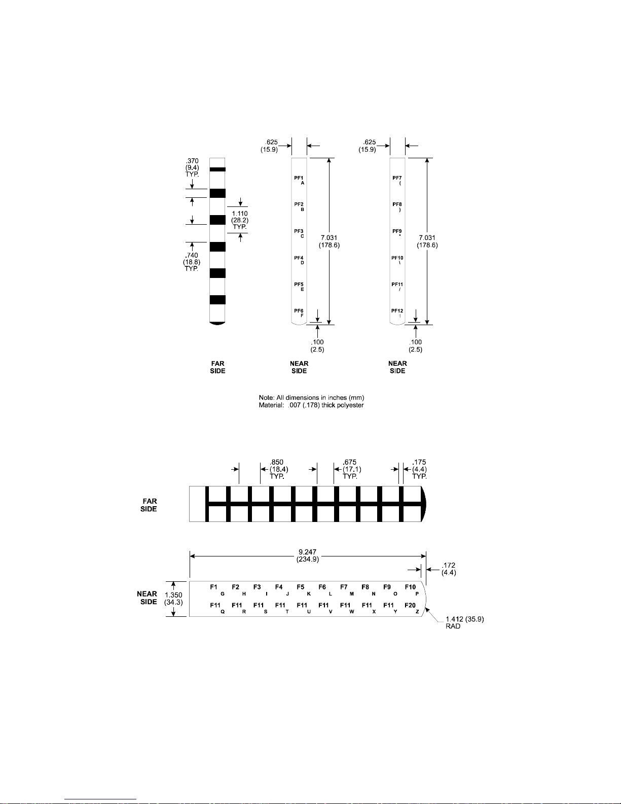
Creating Custom Keypad Inserts (for 3510/3512KP Units)
You can customize your keypad with keypad inserts. Refer to Figures 3-14, 3-15, and
3-16 for insert dimensions and installation.
Figure 3-17. 3510KP/3512KP Keypad Inserts with Dimensions (PF1 – PF12)
Figure 3-18. 3510KP/3512KP Insert with Dimensions (F1 - F20)
35

3500 Flat Panel Industrial PCs
Figure 3-19. 3510KP/3512KP Keypad Insert Position
Creating Custom Keypad Inserts (3535)
You can customize your keypad with keypad inserts. Refer to Figure 3-15 and Figure
3-16 for insert dimensions and installation.
36

Chapter Three - Installation
Figure 3-15. Keypad Inserts with Dimensions (PF1 - PF20)
37

3500 Flat Panel Industrial PCs
Figure 3-16. Keypad Insert with Dimensions (F1 - F20)
Figure 3-15 provides information on positioning keypad inserts.
38

Chapter Three - Installation
Figure 3-17. Keypad Insert Position
Reinstalling Operating Systems
The 3500 CPU ships with MS-DOS pre-installed. Optionally available, are
Microsoft Windows 95, Windows 98, Windows NT, and Windows 2000
operating systems. If you want to install a different operating system, refer to that
operating system’s manual for directions.
MS-DOS reinstallation
If you need to reinstall MS-DOS, refer to the Xycom Automation Workstation
Recovery Media Software Installation Instructions for Microsoft
(shipped with systems pre-installed with MS-DOS). This document is devoted to the
reinstallation of your MS-DOS operating system and drivers utilizing the Recovery
Media provided with your Xycom Automation industrial computer.
NOTE: This procedure assumes that the computer hard disk drive has been completely
corrupted or replaced.
WARNING: This procedure will destroy data that may exist on the hard disk drive.
DOS 6.22
39

3500 Flat Panel Industrial PCs
Windows 95 reinstallation
If you need to reinstall the Windows 95 operating system, refer to the Xycom
Automation Workstation Recovery Media Software Installation Instructions for
Microsoft
This document is devoted to the reinstallation of your Microsoft Windows 95
operating system and drivers utilizing the Recovery Media provided with your
Xycom Automation industrial computer.
NOTE: This procedure assumes that the computer hard disk drive has been completely
corrupted or replaced.
WARNING: This procedure will destroy data that may exist on the hard disk drive.
Windows 95 (shipped with systems preinstalled with Windows 95).
Windows 98 reinstallation
If you need to reinstall Windows 98 refer to the Xycom Automation Workstaion
Recovery Media Software Installation Instructions for Microsoft
(shipped with systems preinstalled with Windows 98). This document is devoted to
the reinstallation of your Windows Workstation operating system and drivers
utilizing the Recovery Media provided with your Xycom Automation industrial
computer.
Windows 98
NOTE: This procedure assumes that the computer hard disk drive has been completely
corrupted or replaced.
WARNING: This procedure will destroy data that may exist on the hard disk drive.
Windows NT reinstallation
If you need to reinstall Windows NT refer to the Recovery for Xycom Automation
Windows NT
This document is devoted to the reinstallation of your Windows NT Workstation
4.0 operating system and drivers utilizing the Recovery Media provided with your
Xycom Automation industrial computer.
NOTE: This procedure assumes that the computer hard disk drive has been completely
corrupted or replaced.
WARNING: This procedure will destroy data that may exist on the hard disk drive.
Note: If you need to reinstall the Windows NT or Windows 95 operating system, you
must have an internal CD-ROM drive or an external parallel port CD-ROM drive.
Windows NT ships only on a CD-ROM disk.
Workstation (shipped with systems preinstalled with Windows NT).
If you want to install a new operating system or re-install a current operating system,
refer to the operating system’s manual for directions.
40

Windows 2000 reinstallation
If you need to reinstall Windows 2000 refer to the Xycom Automation Workstation
Recovery Media Software Installation Instructions for Microsoft
(shipped with systems preinstalled with Windows2000). This document is devoted
to the reinstallation of your Windows2000 Workstation operating system and
drivers utilizing the Recovery Media provided with your Xycom Automation
industrial computer.
NOTE: This procedure assumes that the computer hard disk drive has been completely
corrupted or replaced.
WARNING: This procedure will destroy data that may exist on the hard disk drive.
Installing Drivers
This section describes how to install the drivers associated with the system.
Chapter Three - Installation
Windows 2000
Ethernet Drivers
If Windows 95 or Windows NT 4.0 is pre-installed on your system and you
ordered the Ethernet card option, Ethernet drivers are installed on your hard drive in
the C:\netdrv directory.
If you want to use Ethernet capabilities with Windows 95, your system must have
BIOS revision level 1.1 or higher. If the AHIP4+ board is installed, your system must
have BIOS revision level 1.7 or higher.
If MS-DOS is installed on your system, the Ethernet drivers are supplied on your
hard drive in the C:\netdrv directory, but they are not installed.
To install the MS-DOS Ethernet drivers,
1. At the C: prompt, type “cd netdrv”.
2. Once the C:\netdrv path is specified, type “install”.
3. Follow the on-screen instructions to complete installation.
Note
Note
If you install Windows NT 4.0 or Windows 95 on your system, the Ethernet drivers
that are provided do not work with the Ethernet controller installed. You must use the
drivers provided by Xycom Automation. These drivers can be found on the Ethernet
Drivers disk that ships with your system.
Consult the Info directory on the drivers disk for additional installation information.
41

3500 Flat Panel Industrial PCs
Video Drivers
Video drivers and the expansion utilities are on the diskette included with the
documentation kit as well as on the hard drive.
For the AHIP6+ system, the video drivers are in the following directories:
C:\VGA\C&T554\WIN95
C:\VGA\C&T554\WINNT
C:\VGA\C&T\DOS\UTILITIES
For the AHIP4+ system, the video drivers are in the following directories:
C:\VGA\C&T550\WIN95
C:\VGA\C&T550\WINNT
C:\VGA\C&T\DOS\UTILITIES
Video Expansion
This section deals with the hardware expansion capability of the video controller
chip in DOS applications.
Note
It is not necessary to read this section if you are a Windows or OS/2 user and do not
plan to run DOS applications, and have not modified the default expansion mode in
the BIOS setup,
Unlike a CRT, a flat panel display has a fixed horizontal and vertical resolution.
There are many DOS video modes whose resolution is less than that of a flat panel
display. In order to more efficiently make use of the flat panel display’s active area,
it is necessary to employ an expansion technique which stretches the lower
resolution information to fill the higher resolution of the display. For example, DOS
defaults to VGA video mode 3+. This is an 80 column, 25-row text only screen
whose effective resolution is 640 dots x 400 scan lines. Because of this, the 800 x
600 display of the system will be partially filled by the 640 x 400 resolution of this
particular mode. By enabling the expansion function, these lower resolutions will
better utilize the display by stretching the information in an attempt to fill the
display. Operating systems such as Microsoft Windows 95, and Windows NT use
display drivers to handle the different flat panel displays. Here expansion is not
necessary since there is a specific driver for each resolution display.
Expansion does not add any resolution to the existing information; it simply stretches
the information to better fit the display. Text and graphic screens can look somewhat
grainy from the process of expansion. If the effect of expansion is undesirable, it can
be turned off either in the BIOS setup, or by executing an included utility program.
See the table below for the three utility programs included to allow expansion to be
turned on, turned off, and set back to the BIOS default state and what effect they
have on the display.
42
Video Expansion Options

Chapter Three - Installation
Utility Mode Panel Type/Size
12.1” TFT
EXP_ON.EXE Text Vert/Hor
Expansion On Graphics Vert/Hor
EXP_DEF.EXE Text Vert/Hor
Expansion Default Graphics Off
EXP_OFF.EXE Text Vert/Hor*
Expansion Off Graphics Off
Definitions:
Vert - Vertical only expansion is invoked
Vert/Hor - Vertical and Horizont al expansion is invoked
Expansion Default - The video BIOS default on power up
* Text expansion cannot be turned off
With an 800 x 600 display, the stretching algorithm does not completely fill the
display horizontally or vertically. A greater vertical text expansion can be achieved
by changing to VGA mode 3* (see Note below). This is also an 80 column, 25 row
text mode but with an effective resolution of 640 x 350. The 350 lines stretch better
to fill the 768-line display than does the default DOS mode 3+.
Note
The utility diskette includes a program titled MOD3_350.EXE, to allow switching to
the VGA mode 3*. Another utility program, MOD3_400.EXE, is provided to put the
mode back to the DOS default of 3+.
Windows may come up with a blank screen when using Windows 3.X with
expansion turned on either through the BIOS setup or the EXP_ON.EXE utility. The
two options (second option being the best) for this situation are listed below:
• Option 1 – Pressing the
display, letting you know that pressing
CTRL-ALT-DEL keys simultaneously. A blue screen will
CTRL-ALT-DEL again will reboot the
system or pressing any key will return you to Windows. At this point, press any
key and the normal Windows screen should appear.
• Option 2 – Turn off the expansion, set the BIOS default in the BIOS setup menus
using the appropriate utility as shown in the Video Expansion Options table.
Note
For further assistance, call Xycom Automation technical support at 1-800-289-9266.
43

3500 Flat Panel Industrial PCs
Touchscreen Drivers
If you have a touchscreen factory installed, you will also receive at no charge: MSDOS, and Windows 95 touchscreen drivers on diskette. Touchscreen drivers for
Windows NT (9460-DRVNT) and OS/2 (9460-DRVOS/2) must be purchased
separately.
The Windows 95 touchscreen driver is available in a COM2 and a mouse port
version. Windows NT touchscreen driver is only available in a version for COM2
If you order Windows NT pre-loaded on a system, the Windows NT touchscreen
drivers are provided.
You must install the corresponding touchscreen driver software if you change the
operating system. Refer to the touchscreen manual for instructions.
Note
If you ordered Windows 95 and a touchscreen on your system, the touchscreen driver
has been installed. If you ordered Windows NT, the driver is on diskette and a copy
of the driver file is on the hard drive. Windows NT only supports COM2. Therefore,
the touchscreen will be on the COM2 port and COM2 will not be available for other
use.
Miscellaneous Drivers
Refer to your operating system and peripheral manuals for information on installing
drivers related to these items.
If you had Windows NT preloaded on your system, you may have to purchase and
install an external parallel port CD-ROM drive, or order your system with CD-ROM
drive to install Windows NT drivers. The Windows NT operating system only ships
on CD-ROM.
Note
Note
44

Using a Touchscreen
Xycom Automation’s touchscreen complies with environmental specifications and
maintains a NEMA 4 seal when panel mounted. It remains operational even after 30
million touches. The touchscreen Monitor Mouse driver emulates a Microsoft
mouse.
Depending upon the date of purchase, the Xycom Automation unit will have one of
two possible touchscreen controllers:
• The Microtouch Controller P/N 114084
• The Xycom Controller P/N 140554
These controllers function similarly. However, the following sections require
attention to the type of controller installed.
Microtouch Controller
If MS-DOS, or Windows 95 is installed on your
system, the touchscreen is configured for the mouse port
and the mouse port is unavailable.
Chapter Three - Installation
Note
If Windows NT is installed on your system, the
touchscreen is set up on COM2 and the COM2 port is
unavailable for other use.
To reconfigure the touchscreen to use the COM2 port, perform the
following steps:
1. Disconnect the power.
2. Remove the lid.
Figure 3-17A. Touchscreen Controller Card
3. Remove the touchscreen controller card (Figure 3-
45

3500 Flat Panel Industrial PCs
A
B
CO
Xycom Controller
To reconfigure the touchscreen to use the COM2 port, perform the
following steps:
17A).
4. Reconfigure Jumpers J1-J5. Position A = COM2.
Position B = PS/2 mouse.
5. Reinstall the touchscreen controller card.
6. Reboot the computer.
7. Using the touchscreen manual do the following:
• Load the touchscreen drivers.
• Reconfigure the touchscreen driver for COM2.
• Recalibrate the touchscreen.
8. Replace the lid.
1. Disconnect the power.
2. Remove the lid.
J1
J2
J3
J4
JUMPERS
J5
J7
J8
J9
2
1
TOUCH SCREEN
NTROL CONN.
Figure 3-17B. Touchscreen Controller Card
3. Remove the touchscreen controller card (Figure 3-
17B).
4. Reconfigure Jumpers J1-J9. Position A = COM2.
Position B = PS/2 mouse.
40
39
46
5. Reinstall the touchscreen controller card.
6. Reboot the computer.
7. Using the touchscreen manual, do the following:

• Uninstall the UPDD touch driver.
• Locate the Touch-Base Serial Mode driver on
the Xycom Documentation CD
• Follow the instructions in the readme.txt file for
the installation of the UPDD driver in serial
mode.
8. Replace the lid.
Calibrating the Touchscreen
Depending upon the date of purchase, the Xycom Automation unit will have one of
two possible touchscreen controllers:
• The Microtouch Controller P/N 114084
• The Xycom Controller P/N 140554
Chapter Three - Installation
These controllers function similarly. However, the following sections require
attention to the type of controller installed.
Microtouch Controller
If you need to recalibrate the touchscreen, refer to the
sections in the touchscreen manual that explain
calibrating the touchscreen and using the diagnostic
utility.
Note
The touchscreen and controller are a matched pair
calibrated at the factory.
Xycom Controller
If you need to recalibrate the touchscreen, run the
Pointer Devices Control Panel applet. Select Help for
details about calibrating. For best results, use the 25
point calibration setting with Start In At set to 0.
You need to calibrate the touchscreen if
• The cursor does not follow the movement of your finger or pen
• You adjust the size of the video image or change the video mode
47

3500 Flat Panel Industrial PCs
Installing the System into a Panel
The system’s rugged design allows it to be installed in most industrial environments.
The system is generally placed in a NEMA 4/4X/12 enclosure to protect against
contaminants such as dust, moisture, etc. Metal enclosures also help minimize the
effects of electromagnetic radiation that nearby equipment can generate.
Mounting Considerations
Once you have established a location for the 3500, install it in the enclosure
according to the instructions that follow:
• Select a NEMA rated enclosure and place the unit to allow easy access to the system
ports.
• Account for the unit’s depth when choosing the depth of the enclosure.
• Provide a NEMA 4 seal by mounting the unit in an approved enclosure that has a 14
gauge (0.075"/1.9mm thick) steel or (0.125"/3.2mm thick) aluminum front face.
• Mount the unit in an upright position.
• Place the unit at a comfortable working level.
• Consider locations of accessories such as AC power outlets and lighting (interior
lighting and windows) for installation and maintenance convenience.
• Prevent condensation by installing a thermostat-controlled heater or air conditioner.
• To allow for maximum cooling, avoid obstructing the airflow.
• Place any fans or blowers close to the heat generating devices. If using a fan, make
sure that outside air is not brought inside the enclosure unless a fabric or other
reliable filter is used. This filtration prevents conductive particles or other harmful
contaminants from entering the enclosure.
• Do not select a location near equipment that generates excessive electromagnetic
interference (EMI) or radio frequency interface (RFI) (equipment such as high power
welding machines, induction heating equipment and large motor starters).
• Place incoming power line devices (such as isolation or constant voltage
transformers, local power disconnects, and surge suppressers) away from the system.
The proper location of incoming line devices keep power wire runs as short as
possible and minimizes electrical noise transmitted to the unit.
• Make sure the location does not exceed the unit’s shock, vibration, and temperature
specifications.
• Install in the rack or panel in such a way as to ensure that it does not cause a hazard
from uneven mechanical loading.
• Incorporate a readily accessible disconnect device in the fixed wiring on permanently
connected equipment.
• Avoid circuit overloading of the supply circuit.
48

System Power
Using isolation transformers on the incoming AC power line to the system is always
a good practice. An isolation transformer is especially desirable in cases in which
heavy equipment is likely to introduce noise onto the AC line. The isolation
transformer can also serve as a step-down transformer to reduce the incoming line
voltage to a desired level. The transformer should have a sufficient power rating
(units of volt-amperes) to supply the load adequately.
Proper grounding is essential to all safe electrical installations. Refer to the relevant
Federal, State/Provincial, and local electric codes which provides data such as the
size and types of conductors, color codes and connections necessary for safe
grounding of electrical components. The code specifies that a grounding path must
be permanent (no solder), continuous, and able to safely conduct the ground-fault
current in the system with minimal impedance (minimum wire required is 18 Awg, 1
mm).
Observe the following practices:
• Separate ground wires (P.E. or Protective Earth) from power wires at the point of
entry to the enclosure. To minimize the ground wire length within the enclosure,
locate the ground reference point near the point of entry for the plant power supply.
Chapter Three - Installation
• All electrical racks or chassis and machine elements should be Earth Grounded in
installations where high levels of electrical noise can be expected. The rack/chassis
should be grounded with a ground rod or attached to nearby Earth structure such as a
steel support beam. Each different apparatus should be connected to a single Earth
Ground point in a “star” configuration with low impedance cable. Scrape away paint
and other nonconductive material from the area where a chassis makes contact with
the enclosure. In addition to the ground connection made through the mounting bolt
or stud, use a one-inch metal braid or size #8 AWG wire to connect between each
chassis and the enclosure at the mounting bolt or stud.
Excessive Heat
The units withstand temperatures from 0º to 50ºC. The systems are cooled by
convection, in which a vertical column of air is drawn in an upward direction over
the surface of its components. To keep the temperature in range, the cooling air at
the base of the system must not exceed 50°C. Allocate proper spacing between
internal components installed in the enclosure.
When the air temperature is higher than the specified maximum in the enclosure, use
a fan or air conditioner to lower the temperature.
Electrical Noise
Electrical noise is seldom responsible for damaging components, unless extremely
high energy or high voltage levels are present. However, noise can cause temporary
malfunctions that can result in hazardous machine operation in certain applications.
Noise may be present only at certain times, may appear as widely spread intervals, or
in some cases may exist continuously.
Noise commonly enters through input, output, and power supply lines and may also
be coupled through the capacitance between these lines and noise signal carrier lines.
49

3500 Flat Panel Industrial PCs
This usually results from the presence of high voltage or long, close-spaced
conductors. When control lines are closely spaced with lines carrying large currents,
the coupling of magnetic fields can also occur. Use shielded cables to help minimize
noise. Potential noise generators include switching components relays, solenoids,
motors, and motor starters.
Refer to the relevant Federal, State/Provincial, and local electric codes which
provides data such as the size and types of conductors, color codes and connections
necessary for safe grounding of electrical components. It is recommended that the
high voltage and low voltage cabling be separated and dressed apart. In particular,
the AC cables and switch wiring should not be in the same conduit with all
communication cables.
50

Line Voltage Variation
The unit’s power supply is built to operate with output voltage ranges of 90-132
VAC and 180-264 VAC or 20-36 VDC, whichever applies, and still allow the system
to function within its operating margin. As long as the incoming voltage is adequate,
the power supply provides all the logic voltages necessary to support the processor,
memory, and I/O.
In cases in which the installation is subject to unusual AC line variations, use a
constant voltage transformer to prevent the system from shutting down too often.
However, a first step toward the solution of the line variations is to correct any
possible feed problem in the distribution system. If this correction does not solve the
problem, use a constant voltage transformer.
The constant voltage transformer stabilizes the input voltage to the 3510/3512 by
compensating for voltage changes at the primary in order to maintain a steady
voltage at the secondary. When using a constant voltage transformer, check that the
power rating is sufficient to supply the unit.
Creating a Power Cable
Chapter Three - Installation
This section describes how to create both an AC and DC power cable.
AC Power Cable
You must create an AC power cable to supply power to units with AC power
supplies. You will need the following materials:
• A three-position power connector (supplied).
• A braid/foil shielded power cable, terminated at power source end, with three 18 (1.0
mm), 16 (1.3 mm), or 14 (1.6 mm) AWG solid or stranded copper wire, rated 80º C
or better.
Perform the following steps to create the cable:
1. Cut the wire cable to the desired length.
2. Strip 0.25-inch (6 mm) of insulation from the end of the conductor wire. No bare
wire should be exposed when the cable is connected to the workstation.
3. Tin the wire ends with solder if using stranded wire. This will keep the wire
from fraying.
Warning
When inserting the wire ends of the power cable into the block plug, be sure there is no
exposed wire. Trim the wire ends of the cable or cut a new cable if necessary.
4. Insert the three wire ends of the power cable into the three holes of the block
plug. Insert the Protective Earth GND ground, L1, and L2/N wires into the
corresponding holes, as shown in Figure 3-8. Be sure that no bare wires are
exposed.
51

3500 Flat Panel Industrial PCs
5. Tighten the three screws above the wires to hold them firmly in place.
Never tighten the three screws of the block plug when the cable is connected to a power
source. The screws are conductive and have full contact with the cable wire.
6. Use a cable clamp and #6-32 screw (provided) to secure and provide strain relief
to the power cable. When installing the power cable to the unit, use the securing
screws on each side of the plug. This strain relief is mandatory for hazardous
locations compliance.
Figure 3-21. AC Power Connector
Warning
Warning
Completely loosen the two securing screws on the plug when disconnecting the power
cord from the unit.
DC Power Cable
You must create a DC power cable to supply power to units with DC power supplies.
You will need the following materials:
• A three-position power connector (supplied)
• A braid/foil shielded power cable with three 18 (1.0 mm), 16 (1.3 mm), or 14 (1.6
mm) AWG solid or stranded copper wire, rated 80º C or better.
Perform the following steps to create the DC power cable:
1. Cut the wire cable to the desired length.
2. Strip 0.25-inch (6 mm) of insulation from the end of the conductor wire. No bare
wire should be exposed when the cable is connected to the workstation.
3. Tin the wire ends with solder if using stranded wire. This will stop fraying.
Warning
When inserting the wire ends of the power cable into the block plug, be sure there is no
exposed wire. Trim the wire ends of the cable or cut a new cable if necessary.
52

Chapter Three - Installation
4. Insert the three wire ends of the power cable into the three holes of the block
plug. Insert the Protective Earth GND ground, + (positive), and - (return) wires
into the corresponding holes, as shown in Figure 3.19. Be sure that no bare wires
are exposed.
Figure 3-22. DC Power Connector
5. Tighten the three screws above the wires to hold them firmly in place.
Never tighten the three screws of the block plug when the cable is connected to a power
source. The screws are conductive and have full contact with the cable wire.
6. Use a plastic cable clamp and #6-32 screw (provided) to secure and strain-relief
the cable. When installing the power cable to the unit, use the securing screws on
each side of the plug.
Completely loosen the two securing screws on the plug when disconnecting the power
cord from the unit
Installation is complete once the power and other optional interface cables are installed.
Mounting the Unit
Once the conditions in the preceding sections have been met, follow the instructions
below to mount the unit:
1. Locate a position for your system that meets the specifications required (see
previous sections and Appendix A).
Warning
Warning
2. Cut the hole according to the cutout dimensions in Figure 3.20 or Figure 3.21.
3. Make sure the area around the cutout is clean and free from metal burrs.
4. Install the unit.
53

3500 Flat Panel Industrial PCs
61.6
5. Attach the power cable making sure that the system’s enclosure is grounded
through the power cable.
6. Implement the proper grounding techniques. Establish a ground path from the
unit chassis to the enclosure chassis. A 6-32 threaded ground point hole is
provided on the bottom panel of the unit.
7. Tighten the 12-#10 nuts to 25 lbs-inch (2.8 Newton-meters) (28Kgf cm).
System Cutout Dimensions
3510(T)/3512(T)
6.150 [156.21]
2.150 [54.61]
.315 [8.00]
12.300 [312.42]
10.150 [257.81]
2]
10.300 [2
11.670 [2 96.42 ]
5.150 [1 3 0.81]
1.315 [33.40]
1.650 [41.91]
8.650 [219.71]
9.630 [244.60]
ø.250 [ø6.35]
Figure 3-23. 3510/3512 System Cutout Dimensions (inches [mm])
54

0
.350 [8.89]
Chapter Three - Installation
3510KP/3512KP, 3510KPT/3512KPT
15.800 [401.32]
14.150 [359.41]
7.900 [200.66]
1.650 [41.91 ]
5.775 [146.69]
[293.37]
10.400 [264.16]
11.55
3.85 7 [97.97]
.457 [11.61]
8.085 [205.36]
12.085 [306.96]
13.170 [334.52]
.800 [20.32]
1.150 [29.21]
10.850 [ 275.59]
15.100 [383.54]
ø.250 [ø6.35]
Figure 3-24. 3510KP/3512KP System Cutout Dimensions (inches [mm])
3535KPM and 3535T
18.3 12 [4 65 .12]
14.457 [367.21]
9.157 [232.59]
17.400 [441.96]
5.085 [129.16]
.685 [ 1 7.40]
1.085 [27.56]
12.370 [314.20]
Figure 3-25. 3535KP System Cutout Dimensions (inches [mm])
ø.250 [ø6.35]
55

3500 Flat Panel Industrial PCs
Power Supply
The power supply provides 80 watts of output throughout the system’s temperature
range. The expansion power is limited as shown in the following table.
Voltage Available Current
+5 VDC 6.17A +3.3 9A
+12 VDC 1.88A +5 6A
-12 VDC 0.71A +12 1.5A
a
Total expansion power not to exceed 46 watts
b
Total expansion power not to exceed 48 watts
Available Expansion Current
AHIP4+ (5x86 processors) aAHIP-370
(Celeron and Pentium II/III processors)
-12 .45A
b
56

Hazardous Locations Installations
Xycom Automation designed the systems to meet the requirements of Class I,
Division 2 Hazardous Locations applications. Division 2 locations are those
locations that are normally non-hazardous, but could become hazardous due to
accidents that may expose the area to flammable vapors, gases or combustible dusts.
These systems have been designed as non-incendiary devices. They are not
intrinsically safe and should never be operated within a Division 1 (normally
hazardous) location when installed as described here. Nor should any peripheral
interface device attached to these systems be located within Division 1 locations
unless approved and/or certified diode barriers are placed in series with each
individual signal and DC power line. Any such installations are beyond the bounds
of Xycom design intent. Xycom Automation accepts no responsibility for
installations of this equipment or any devices attached to this equipment in Division
1 locations.
It is the customer's responsibility, when adding additional cards, that they meet
operating conditions for Class I, Division 2 hazardous locations.
Chapter Three - Installation
Note
It is the responsibility of the customer to ensure that the product is properly rated for
the location. If the intended location does not presently have a Class, Division, and
Group rating, then users should consult the appropriate authorities having
jurisdiction in order to determine the correct rating for that Hazardous Location.
In accordance with Federal, State/Provincial, and Local regulations, all hazardous
locations installations should be inspected by the appropriate authority having
jurisdiction prior to use. Only technically qualified personnel should install, service,
and inspect these systems.
Safety A gency A pprov al
The Xycom Automation systems have the following approvals:
• Underwriters Laboratories Inc., UL 1604 Standard for Safety. Electrical equipment
for use in Class I and Class II, Division 2, and Class III hazardous (classified)
locations.
• Underwriters Laboratories Inc., UL 1950, Information Technology Equipment. (UL
recognized, File E181675)
• Canadian Standard Association, Specification C22.2 No. 213-M1987. Non-
incendiary electrical equipment for use in Class I, Division 2 hazardous locations.
• Canadian Standards Association, Specification C22.2 No. 950, Information
Technology Equipment. (CUL recognized, File E181675).
• EN60950, Information Technology equipment
57

3500 Flat Panel Industrial PCs
•
Suitable for use in Class I, Division 2 Groups A, B, C, and D, and Class II, Division 2,
Groups F and G hazardous locations or non-hazardous locations only.
Substitution of components may impair suitability for Class I, Class II, Division 2.
La substitution de composants peut rendre ce materiel inacceptable pour les
emplamements de classe I, II, Division 2.
Do not disconnect equipment unless the power has been switched off or the area is
known to be non-hazardous.
Warning
Warning - Explosion Hazard
Advertissment Risque D’ Explosion
Warning - Explosion Hazard
Advertissment Risque D’ Explosion
Avant de deconnecter l’equipment, coupler le courant ou s’assurer que l’emplacement
est designe non dangereux.
Advertissment Risque D’ Explosion
Dans les situations hasardees, couper la courant avant de remplacer ou de cabler les
modules.
Warning - Explosion Hazard
When in hazardous locations, turn off power before replacing or wiring modules.
Warning
In order to maintain a safe condition, do not use an external keyboard or mouse when
the unit is operating in a hazardous environment.
58

Definitions
The following Class and Division explanations are derived from Article 500
(Sections 5 and 6) of the United States National Fire Protection Agency National
Electric Code (NFPA 70, 1990). They are not complete and are included here only
for a general description for those not familiar with generic hazardous locations'
requirements.
Persons responsible for the installation of this equipment in Hazardous Locations are
responsible for ensuring that all relevant codes and regulations related to location
rating, enclosure, and wiring are met.
Class I Locations
Class I locations are those in which flammable gases or vapors are or may be present
in the air in quantities sufficient to produce explosive or ignitable mixtures.
Class II Locations
Class II locations are those that are, or may become, hazardous because of the
presence of combustible dust.
Chapter Three - Installation
Division 1 Locations
A Division 1 location is one in which flammable or ignitable gasses, vapors, or
combustible dusts and particles can exist due the following conditions:
• Normal operating conditions.
• Because of repair, maintenance conditions, leakage, or where mechanical failure or
abnormal operation of machinery or equipment might release or cause explosive or
ignitable mixtures to be released or produced.
• Combustible dusts of an electrically conductive nature may be present in hazardous
quantities.
Note
Xycom Automation systems are not suitable for installation within Division 1
locations.
Note
Electrical equipment cannot be installed in Division 1 locations unless they are
intrinsically safe, installed inside approved explosion-proof enclosures, or installed
inside approved purged and pressurized enclosures.
59

3500 Flat Panel Industrial PCs
Division 2 Locations
Division 2 locations are listed below:
• Class I volatile flammable liquids or flammable gasses are handled, processed, or
used, but confined within closed containers or closed systems from which they can
escape only in cases of accidental rupture or breakdown of such enclosures or
systems, or in case of abnormal operation of equipment.
• Ignitable concentrations of Class I vapors or gasses are normally prevented by
positive mechanical ventilation, but which may become hazardous due to mechanical
failure of those ventilation systems.
• Location is adjacent to a Division 1 location.
• Class II combustible dust is not normally in the air in quantities sufficient to produce
explosive or ignitable mixtures. Dust accumulations are normally insufficient to
interfere with normal operation of electrical equipment or other apparatus.
Combustible dust may be in suspension in the air as a result of the following:
malfunctioning of handling or processing equipment; combustible dust
accumulations on, or in the vicinity of electrical equipment; may be ignitable by
abnormal operation or failure of electrical equipment.
Hazardous Locations Group Ratings
All electrical equipment that is approved for use in hazardous locations must include
a group rating. Various flammable and combustible substances are divided into these
groups as a function of their individual maximum experimental safe gap (MESG),
explosion pressure, and ignition temperature.
Component temperatures and the potential for spark based upon voltage, current, and
circuit characteristics, within electrical equipment, will determine what the
equipment group rating will be. A device approved for installation within Class I,
Group A locations may also be used in Groups B, C, or D.
Approved Class I equipment may not be suitable for Class II installations. Class I
includes Groups A, B, C, and D. Class II includes Groups F, and G.
Enclosures
The systems are designed for installation within a clean and dry enclosure for both
ordinary and hazardous locations. The front panel meets the requirements of UL and
CSA Type 4, 4X, and 12 enclosures. The enclosure used for Class I hazardous
locations should have a minimum rating of Type 12 (NEMA 12, IP 5X). However,
Type 4 (IP 6X) enclosures are strongly recommended.
Note
60
Warning

The optional floppy disk/keyboard port access door must be closed and latched at all
times in order to maintain a proper seal against the intrusion of water and dust.
Panel flatness and rigidity are important if a proper panel seal is to be maintained. If
non-metal type enclosures, such as plastic or fiberglass, are to be used, install a rigid
metal stiffener behind the front panel. Failure to do so may result in an inadequate
panel seal due to flexure of the front panel material between the stud mounts.
Tighten the nuts on the mounting studs to 25-inch pounds.
The requirements for enclosure fittings, conduit, and wiring vary according to the
specific rating of the location and the type of flammable or combustible material
involved. Those requirements are beyond the scope of this document and it is the
responsibility of the customer to ensure that their installation is compliant with codes
and regulations that apply to their specific location. Reference NFPA 70, Article 500
for specific regulations in the United States.
Power Switch
The 3500 systems do not have a power switch. The amount of input power required
by these systems classifies the power switch as an incendiary device because the
voltage and current across the make/break device are capable of creating a spark.
Chapter Three - Installation
Hazardous locations' regulations require that a power switch rated for ordinary
locations may be used if it is located in an area specified as non-hazardous.
However, limits in cable length between the workstation and the power switch may
apply. Otherwise the switch must be compliant with Class I, Division 1 requirements
(intrinsically safe). These switches are built in a manner that prevents the possibility
of a spark when contacts are made or broken.
Use suitable UL listed and/or CSA Certified Class I, Division 1 switches in
hazardous locations. These switches are available from a wide number of sources. It
is the responsibility of the customer to ensure that the power switch selected for their
installation has the correct hazardous locations rating for the location in which it is
installed.
Cable Connections
Division 2 hazardous location regulations require that all cable connections be
provided with adequate strain relief and positive interlock. Never connect or
disconnect a cable while power is applied at either end of the cable.
Communication Cable Interface
All communication cables should include a chassis ground shield. This shield should
include both copper braid and aluminum foil. The D-sub style connector housing
should be a metal conductive type (e.g., molded zinc) and the ground shield braid
should be well terminated directly to the connector housing. Do not use a shield
drain wire.
The outer diameter of the cable must be suited to the inner diameter of the cable
connector strain relief in order to ensure that a reliable degree of strain relief is
maintained. Always secure the D-Sub connectors to the workstation mating
connectors via the two screws located on both sides.
61

3500 Flat Panel Industrial PCs
Never connect or disconnect the communication cables while power is applied at either
end of the cable. This may result in an incendiary spark. Permanent damage to the
workstation communication components may occur.
Operation and Maintenance
The systems have been designed for compliance with relevant spark ignition tests.
However, please note that the workstation front panel contrast adjustment tactile
switches and keyboard connector are the only make/break components intended to be
exercised by the operator in the course of normal operation.
In order to maintain a safe condition, never use an external keyboard or mouse when
the unit is operating in the presence of a hazardous environment.
Warning
Warning
With respect to Hazardous Location installations, always observe the following rules:
1. Always install the workstations within an enclosure suitable for the specific
application. General purpose enclosures may be acceptable for Class I
applications but are never acceptable for Class II applications. Type 4 (IP 65)
enclosures are recommended even when not required by regulations.
2. If present, keep enclosure doors or openings closed at all times, to avoid the
accumulation of foreign matter inside the workstation.
3. Never subject the unit to any installation or service procedures unless power is
known to be removed and the area is known to be non-hazardous. This includes
the installation or removal of power cables, communication cables, or removal of
the rear cover of the unit.
4. Only technically qualified service personnel should perform all installation and
service. These workstations are designed to require no service in the course of
normal operation by an operator.
62

Chapter Four – Keypad Utility
Chapter 4 - Keypad Utility for 3510KP/3512KPM
A Keypad Utility lets the user redefine all keypad keys with new scan codes using
utility software.
Note
The keypad switch arrays are disabled while the utility is running .
Loading the Keypad Utility
Note
You need MS-DOS® 3.2 or higher to run the utility. It will NOT work if you are
running Windows® 95 or Windows NT®. However, the utility will run under
Windows® 95 in DOS mode.
You can run this utility from the disk or copy it onto your hard drive. To run from
disk, change the directory to the appropriate drive and type. To load the utility onto
your hard drive, create a subdirectory, and copy all the files on the disk into that
subdirectory. Enter the subdirectory and type.
Using the Keypad Utility
The utility uses a menu bar and pull-down menu system. All menu bars are displayed
across the top of the screen. “Utility” and the current menu titles are shown at the
bottom of the screen (see figure 4-1).
You need a full-stroke keyboard to enter keystrokes while recording a new key
macro, editing an existing macro, and entering utility commands. All keys on the
keypads are redefinable. While the utility is running, the keypads are disabled.
Dialog boxes appear for user prompts and to display error and user advice messages.
Two keys can be used to exit from the menus:
• ESC moves to the previous menu or out of the utility from the Main Menu.
• F1 returns to the current menu headings in some of the menus where Exit can
be chosen to exit this menu.
Keys specific to each menu are shown at the bottom of each screen.
63

3500 Flat Panel Industrial PCs
Startup
Type KPUTIL to run the full Keypad utility.
Utility Batch Mode
A mode is also available for reprogramming keypads from a batch file. This feature
is useful if you wish to reprogram many units with customized keypad macros
without having to enter the full utility for each unit. Once the full utility has been
used to create and save keypad macros, the files containing these macros can be
included on a disk with the utility and then used to reprogram other units from a
batch file.
The command filename runs the utility batch mode. Filename is the file containing
the new keypad macros. You must include the filename extension. For example, the
batch file def3512.pkm will reprogram the keypad with def
ault values.
Main Menu
The Main Menu is shown illustrated. Each menu option is described in the next few paragraphs.
Exit Files Macros Upload Download Utilities
Xycom Automation KP Utility: MAIN L-Arrow, R-Arrow, Enter
Figure 4-1. Main Menu
Exit
Exit closes open files and exits the utility. ESC can also be used for this purpose and
for exiting the other menus.
64

Files Menu
Open
Close
Chapter Four – Keypad Utility
Files containing keypad macro sets (a macro for each key) may be saved on disk and
loaded into memory to view, edit, teach, or download to the keyboard controller.
Some of these files may be included in the utility package for use in reconfiguring
the keypads for different software packages and as templates for defining completely
new keypad macro sets.
When you choose Files, a pull-down menu is displayed that provides the following
choices: Open, Close, Save, Save As, Delete, and Exit.
Opens a file that contains a macro set for the keypad and loads the contents into
memory. Any macro set in memory is overwritten. Once loaded, the macro set is
available to edit, view, teach, and/or download to the keyboard controller.
Clears the macro set from memory and closes the file from which they came.
Save
Copies the macro set from memory back into its original file. The original file
contents are overwritten.
Save As
Creates a new file under the specified name and copies the macro set from memory
into it. For example, to define different sets of codes, save each set under a different
name and download the one you wish to use.
Delete
Deletes a file.
Exit
Returns to the Main Menu.
Macros Keypad Type Menu
When you select Macros, a pull down menu displays and provides the following
choices: Function Keys, Alpha Keys, and Exit. Once function or alpha
is selected the menu displays the following choices once the Macros menu is chosen:
Exit, View, Teach, and Edit.
65

3500 Flat Panel Industrial PCs
You must have a macro file in memory before the Macros Menu is available. To load a
macro file, either Open a file or Upload macros.
Function Keys
Selects the function keys on the keypad to either view, edit, or teach.
Alpha Keys
Selects the alpha keys on the keypad to either view, edit, or teach.
Exit
Returns to the main menu.
Macros Edit Menu
Note
Exit
View
Returns to the Main Menu.
Lets you view, but not edit, the macro for the selected key. When View is chosen,
the Exit option is displayed on the menu bar and a graphic representation of the
chosen keypad is shown. Select Exit from the View Menu to return to the Macros
Menu. To select a key to view, use the arrow keys to position the cursor on the
desired key and press
The ASCII line displays each keycode as the keys it represents on the full stroke
keyboard. Special labels are used for certain keys (e.g., Spc for space bar, UAr for up
arrow, and bk for the break code prefix). The code line is displayed in either Hex or
decimal, as explained below. There is a one-to-one correspondence between the
ASCII and code lines to help interpret the code line.
While viewing the macro, the menu bar displays two options: Exit and Hex/Decimal.
Exit returns to the View Menu, while Hex/Decimal toggles between displaying the
macro in hex or decimal format. Default is Hex. When Hex is chosen, the keycodes
are displayed as hexadecimal value scan codes. When Decimal is chosen, the
keycodes are displayed as the decimal equivalent of the hex codes.
For example, the macro abc would be displayed as 1C F0 1C 32 F0 32 21 F0 21 in
hex, and 28 240 28 50 240 50 33 240 33 in decimal.
ENTER. The macro is displayed as two lines—ASCII and code.
66

Teach
Edit
Chapter Four – Keypad Utility
Allows you to record up to 105 keystrokes in a macro. When selected, a graphic
representation of the keypad currently in memory displays. Menu bar choices are
Exit, ASCII/Hex/Decimal, and Click ON/OFF. Exit returns to the Macros menu.
ASCII/Hex/Decimal chooses the format to display the keystrokes as they are
entered. Default is ASCII. Click is not supported.
To select a key to define, use the arrow keys to position the cursor on the desired key
and press
ENTER. After a key is selected, the utility records every key stroke on the
external full-stroke keyboard in a macro assigned to the chosen key. As the keys are
entered they are displayed using the chosen format.
to the Teach Menu, so it is not a recordable key. However,
ESC stops recording and returns
ESC can be included in a
macro by using the editor. Changes made to the macros in the Teach Menu are not
programmed until you select Download.
Displays a graphic representation of the keypad in memory and a menu bar
displaying Exit, Click, and ON/OFF. Exit returns to the Macros menu. Click is not
supported. To select a key to edit, use the arrow keys to position the cursor on the
desired key and press
ENTER.
Cut
In edit mode, the macro is displayed as two lines. The top line (the edit line) displays
the macro in either hex or decimal format and is the line in which the actual editing
takes place. The bottom line (the ASCII line) displays the macro in ASCII format
and is not user configurable. This line helps keep track of which part of the macro
you are editing, and will be updated by the utility as editing takes place. For
example,
edit line 1275F075
F0 12 1C F0 1C
12 22 F0 22 F0
12 0
ASCII line sh 8 bk 8
bk sh a bk a
sh X bk X bk
sh EOM
The insert, delete, and cursor control keys are active for editing.
When a key is selected from the Edit Macro option, the menu bar displays the
following choices: Exit, Cut, Copy, Paste, Codes, Hex/Decimal,
and I/O (Insert/Overtype). The macro for the chosen key is also displayed.
Deletes a sequence of scan codes from the macro. To select a section to cut:
1. Place the cursor on the first character to cut.
2. Press
3. Press
F1 and select CUT.
ENTER. Cut should still be highlighted, but the cursor will appear on the
Edit line. Move the cursor on the last character to cut and press
ENTER.
67

3500 Flat Panel Industrial PCs
4. The last character of every macro is the end of the macro (EOM) and cannot be
deleted.
Copy
Copies a sequence of scan codes from the macro into memory. To select the section
to copy:
1. Place the cursor on the first character to copy. Press
2. Press
3. Move the cursor on the last character to copy and press
The copied item does not appear on the screen until you select Paste.
Paste
Insert a sequence of scan codes (which were saved in memory using Copy) into the
macro. To paste a sequence of scan codes that were previously copied, position the
cursor where you want the text to appear and then press
press
Codes
Displays a table of keys and their scan codes in Hex. See the Codes section later in
this chapter for a complete code listing.
Hex/Decimal
Toggles between displaying the scan codes in Hex and Decimal formats.
F1 and select Copy.
ENTER. Copy should still be highlighted, but the cursor will appear on the
Edit line.
ENTER.
F1. Select Paste and then
ENTER.
Insert
Toggles between insert and overtype mode.
Upload Menu
Use the Upload Menu to choose which data to load. Choices in this menu are:
Combo keypad, Version, and Exit.
Combo Keypad
Commands the keyboard controller to send its entire macro set for the keypad.
Version
Commands the keyboard controller to send its firmware revision number.
68

Exit
Returns to the Main Menu.
A checksum will be calculated during transmission and an error message displays if
an error occurs.
Download Menu
Any macro set previously programmed is overwritten when you select Download.
Chapter Four – Keypad Utility
Note
Only one macro set may reside in memory at one time.
Note
Download sends the set of keypad macros to the keyboard controller. The macro set
must reside in memory before it can be downloaded. A checksum is calculated
during transmission and an error message displays if an error occurs.
As the macro is sent, keyboard controller programs its EEPROM with the new
macros which become the new key definitions for the keypad.
Utilities Menu
When Utilities is selected, a menu bar displays four choices: Func Lock ON,
Func Lock OFF, Clear EEPROM, and Exit.
Func Lock ON
Not available on the 3510KP/3512KP.
Func Lock OFF
Not available on the 3510KP/3512KP.
Clear EEPROM
Erases the EEPROM memory. This clears the entire keypad macro set. After using
this feature, the unit should be turned off and then on. This will initialize the
EEPROM with the default settings.
69

3500 Flat Panel Industrial PCs
Exit
Returns to the Main Menu.
Codes
Special keyboard controller codes replace the standard IBM scan codes for 101-key
keyboard enhanced keys in macros that use these keys. The special scan codes are
listed in the table below:
Special Scan Codes
Code Meaning
E2
E3
E4
E5
E6
E7
E8
E9
EA
EB
EC
ED
EE
Insert
Home
Page Up
Delete
End
Page Down
Up Arrow
Left Arrow
Right Arrow
Down Arrow
Forward Slash
Print Screens/Sys Rq
Pause/Break
The following table lists the default keypad keycodes the utility produces.
70

Default Keypad Keycodes
Chapter Four – Keypad Utility
3512KP
Description of
key
PF1 / A F21 14 05 F0 05 F0 14 A 1C F0 1C
PF2 / B F22 14 06 F0 06 F0 14 B 32 F0 32
PF3 / C F23 14 04 F0 04 F0 14 C 21 F0 21
PF4 / D F24 14 0C F0 0C F0 14 D 23 F0 23
PF5 / E F25 14 03 F0 03 F0 14 E 24 F0 24
PF6 / F F26 14 0B F0 0B F0 14 F 2B F0 2B
F1 / G F1 05 F0 05 G 34 F0 34
F2 / H F2 06 F0 06 H 33 F0 33
F3 / I F3 04 F0 04 I 43 F0 43
F4 / J F4 0C F0 0C J 3B F0 3B
F5 / K F5 03 F0 03 K 42 F0 42
F6 / L F6 0B F0 0B L 4B F0 4B
F7 / M F7 83 F0 83 M 3A F0 3A
F8 / N F8 0A F0 0A N 31 F0 31
F9 / O F9 01 F0 01 O 44 F0 44
F10 / P F10 09 F0 09 P 4D F0 4D
F11 / Q F11 12 05 F0 05 F0 12 Q 15 F0 15
F12 / R F12 12 06 F0 06 F0 12 R 2D F0 2D
F13 / S F13 12 04 F0 04 F0 12 S 1B F0 1B
F14 / T F14 12 0C F0 0C F0 12 T 2C F0 2C
F15 / U F15 12 03 F0 03 F0 12 U 3C F0 3C
F16 / V F16 12 0B F0 0B F0 12 V 2A F0 2A
F17 / W F17 12 83 F0 83 F0 12 W 1D F0 1D
F18 / X F18 12 0A F0 0A F0 12 X 22 F0 22
F19 / Y F19 12 01 F0 01 F0 12 Y 35 F0 35
F20 / Z F20 12 09 F0 09 F0 12 Z 1A F0 1A
PF7 / ( F31 11 05 F0 05 F0 11 ( 12 46 F0 12 F0 46
PF8 / ) F32 11 06 F0 06 F0 11 ) 12 45 F0 12 F0 45
PF9 / * F33 11 04 F0 04 F0 11 * 12 3E F0 12 F0 3E
PF10 / \ F34 11 0C F0 0C F0 11 \ 5D F0 5D
PF11 / / F35 11 03 F0 03 F0 11 / 4A F0 4A
PF12 / : F36 11 0B F0 0B F0 11 : 12 4C F0 12 F0 4C
CTRL CTRL 14 F0 14 CTRL 14 F0 14
SHIFT SHIFT 12 F0 12 SHIFT 12 F0 12
INS INS 70 F0 70 INS 70 F 0 70
ALT ALT 11 F0 11 ALT 11 F0 11
TAB TAB 0D F0 0D TAB 0D F0 0D
DEL DEL 71 F0 71 DE L 71 F0 71
F/A
SPACE SPACE 29 F0 29 SPACE 29 F0 29
+ + 79 F0 79 + 79 F0 79
1 1 16 F0 16 1 16 F0 16
2 2 1E F0 1E 2 1E F0 1E
3 3 26 F0 26 3 26 F0 26
4 4 25 F0 25 4 25 F0 25
5 5 2E F0 2E 5 2E F0 2E
6 6 46 F0 46 6 46 F0 46
7 7 25 F0 25 7 25 F0 25
8 8 3E F0 3E 8 3E F0 3E
F/A key led OFF ( Function Mode ) F/A key led ON ( Alpha Mode )
Keyboard
Equivalent
Make
Codes
Break Codes Keyboard
Equivalent
Make
Codes
Break
Codes
71

3500 Flat Panel Industrial PCs
3512KP
Description of
key
9 9 46 F0 46 9 46 F0 46
. . 49 F0 49 . 49 F0 49
0 0 45 F0 45 0 45 F0 45
- - 7B F0 7B - 7B F0 7B
BACKSPACE BACK SPACE 66 F0 66 BACK SPACE 66 F0 66
up arr up arr E0 12
PREV PgUp E0 12 E07DE0 F0 7D
left arr left arr E0 12 E06BE0 F0 6B
][ HOME E0 12 E06CE0 F0 6C
right arr ri ght arr E0 12 E074E0 F0 74
ESC ESC 76 F0 76 ESC 76 F0 76
down arr down arr E0 12 E072E0 F0 72
NEXT PgDn E0 12 E07AE0 F0 7A
ENTER ENTER 5A F0 5A ENTER 5A F0 5A
F/A key led OFF ( Function Mode ) F/A key led ON ( Alpha Mode )
Keyboard
Equivalent
Make
Codes
E0 75
Break Codes Keyboard
Equivalent
E0 F0 75
E0 F0 12
E0 F0 12
E0 F0 12
E0 F0 12
E0 F0 12
E0 F0 12
E0 F0 12
Contrast Up E0 12
PgUp E0 12 E07DE0 F0 7D
Contrast Down E0 12 E06BE0 F0 6B
HOME E0 12 E06CE0 F0 6C
Contrast Up E0 12 E074E0 F0 74
Contrast Down E0 12 E072E0 F0 72
PgDn E0 12 E07AE0 F0 7A
Make
Codes
E0 75
Break
Codes
E0 F0 75
E0 F0 12
E0 F0 12
E0 F0 12
E0 F0 12
E0 F0 12
E0 F0 12
E0 F0 12
NOTE: F11-F20 = SHIFT F1-F10
F21-F26 = CTRL F1-F6
F31-F36 = ALT F1-F6
Note
If you make any changes to your keypad and want to set it back to the default settings,
open the file titled DEF9462.PKM from the File/Open menu and then download it
from the download menu. Do not save any changes to the default files.
72

Chapter Five – Keypad Utility for 3535
Chapter 5 - Keypad Utility for the 3535 KPM
The 3535KPM Keypad Utility lets users redefine all keypad keys with new scan
codes using utility software. Use an external full-stroke PC/AT keyboard to access
the utility (you cannot redefine the keyboard).
Note
The keypad switch arrays are disabled while the k ey pad utility is running.
Loading the Keypad Utility
Note
You need MS-DOS 3.2 or higher to run the keypad utility. It will not work if you are
running Windows 95 or Windows NT. However, the keypad utility will run under
Windows 95 in DOS mode.
You can run this utility directly from the disk or copy it onto your hard drive. To run
the keypad utility from the disk, change the directory to the appropriate drive and
type
kputil. To load the utility onto your hard drive, create a subdirectory for the files,
and copy all the files on the disk into that subdirectory. Enter the subdirectory and
type kputil.
Using the Keypad Utility
The keypad utility uses a menu bar and pull-down menu system. All menu bars are
displayed across the top of the screen. “Xycom Automation KP Utility” and the
current menu titles are shown at the bottom of the screen (see Figure 4-1).
A full-stroke keyboard is needed to enter keystrokes while recording a new key
macro, editing an existing macro, and entering utility commands. You can redefine
all keys on the keypads. While the utility is running, the keypads are disabled.
Dialog boxes appear for user prompts and to display error and user advice messages.
Two keys allow you to exit the menus:
• ESC
• F1 returns to the current menu headings in some of the menus where Exit can be
moves to the previous menu or out of the utility from the Main Menu.
chosen to exit this menu.
Keys specific to each menu are shown at the bottom of each screen.
73

3500 Series Flat Panel Industrial PC
Startup
Type kputil to run the full keypad utility.
Utility Batch Mode
You can also use a batch file to reprogram keypads. This feature is useful if you wish
to reprogram many units with customized keypad macros without having to enter the
full keypad utility for each unit. Once the full utility has been used to create and save
keypad macros, the files containing these macros can be included on a disk with the
keypad utility and then used to reprogram other units from a batch file.
The command keypad filename runs the keypad utility batch mode.
“Filename” is the file containing the new keypad macros. The filename extension
must be included.
Main Menu
Figure 4-1 illustrates the Main Menu.
Exit Files Macros Upload Download Utilities
Xycom Automation KP Utility: MAIN L-Arrow, R-Arrow, Enter
Figure 4-1. Main Menu
Exit
Exit closes open files and exits the utility. ESC can also be used for this purpose and
for exiting the other menus.
74

Files Menu
Chapter Five – Keypad Utility for 3535
You can save files containing keypad macro sets (a macro for each key) on disk, and
then loaded them into memory to view, edit, teach, or download to the keyboard
controller. Some of these files may be included in the utility package for use in
reconfiguring the keypads for different software packages, and as templates for
defining completely new keypad macro sets.
When you choose File, a pull-down menu will display the following choices:
Open, Close, Save, Save As, Delete, and Exit. The following table describes the
menu commands.
Command Description
Open Opens a file that contains a macro set for the keypad and loads the
contents into memory. Any macro set in memory is overwritten. Once
loaded, the macro set is available to edit, view, teach, or download to the
keyboard controller.
Close Clears the macro set from memory and closes the file from which they
came.
Save Copies the macro set from memory back into its original file. The original
file contents are overwritten.
Save As Creates a new file under the specified name and copies the macro set
from memory into it. For example, to define different sets of codes, save
each set under a different name and download the one you wish to use.
Delete Deletes a file.
Exit Returns to the Main Menu.
NOTE: The 3535KPM uses 3515KP files.
Macros Keypad Type Menu
When you select Macros, a pull down menu displays and provides the following
choices: Function Keys, Alpha Keys, and Exit. Also, another pull down menu
displays the following choices once the Macros menu is chosen: Exit, View, Teach,
and Edit.
You must have a macro file in memory before the Macros Menu is available. To load a
macro file, open a file or upload macros.
Command Description
Function Keys Selects the function keys on the keypad to either view, edit, or teach.
Alpha Keys Selects the alpha keys on the keypad to either view, edit, or teach.
Exit Returns to the main menu.
Note
75

3500 Series Flat Panel Industrial PC
Macros Edit Menu
Command Description
Exit Returns to the Main Menu.
View Allows you to view, but not edit, the macro for the selected key. When View is chosen,
the Exit option is displayed on the menu bar and a graphic representation of the
chosen keypad is shown. Select Exit from the View Menu to return to the Macros
Menu. To select a key to view, use the arrow keys to position the cursor on the desired
key and press
line displays each keycode as the keys it represents on the full-stroke keyboard.
Special labels are used for certain keys (e.g., Spc for space bar, UAr for up arrow, and
bk for the break code prefix). The code line is displayed in either Hex or decimal.
There is a one-to-one correspondence between the ASCII and code lines.
While viewing the macro, the menu bar displays two options: Exit and Hex/Decimal.
Exit returns to the View Menu, while Hex/Decimal toggles between displaying the
macro in hex or decimal format. When Hex is chosen, the keycodes are displayed as
hexadecimal value scan codes. When Decimal is chosen, the keycodes are displayed
as the decimal equivalent of the hex codes.
For example, the macro abc would be displayed as 1C F0 1C 32 F0 32 21 F0 21 in
hex, and 28 240 28 50 240 50 33 240 33 in decimal.
Teach Allows you to record up to 105 keystrokes in a macro. When selected, a graphic
representation of the keypad currently in memory displays. Menu bar choices are Exit,
ASCII/Hex/Decimal, and Click ON/OFF. Exit returns to the Macros menu.
ASCII/Hex/Decimal specifies the format to display the keystrokes as they are entered.
Default is ASCII. Click is not supported.
To select a key to define, use the arrow keys to position the cursor on the desired key
and press
external full-stroke keyboard in a macro assigned to the chosen key. As the keys are
entered, they are displayed using the chosen format.
to the Teach Menu, so you cannot record the
in a macro by using the editor. Changes made to the macros in the Teach Menu are
not programmed until you select Download.
ENTER. The macro is displayed as two lines: ASCII and code. The ASCII
ENTER. After you select a key, the utility records every keystroke on the
ESC stops recording and returns
ESC key. However, ESC can be included
Command Description
Edit Displays a graphic representation of the keypad in memory and a menu bar displaying
Exit, Click, and ON/OFF. Exit returns to the Macros menu. Click is not supported. To
select a key to edit, use the arrow keys to position the cursor on the desired key and
ENTER.
press
In edit mode, the macro is displayed as two lines. The top line (the edit line) displays
the macro in either hex or decimal format and is the line in which the editing takes
place. The bottom line displays the macro in ASCII format; it is not user configurable.
This line keeps track of which part of the macro you are editing, and is updated by the
utility as editing takes place.
The insert, delete, and cursor control keys are active for editing. When a key is
selected from the Edit Macro option, the menu bar displays the following choices: Exit,
Cut, Copy, Paste, Codes, Hex/Decimal, and I/O (Insert/Overtype). The macro for the
chosen key is also displayed.
Cut deletes a sequence of scan codes from the macro. To select a section to cut:
1. Place the cursor on the first character to cut.
76

Chapter Five – Keypad Utility for 3535
Upload Menu
2. Press
3. Press
F1 and select CUT.
ENTER. Cut should still be highlighted, but the cursor will appear on the Edit
line. Move the cursor on the last character to cut and press
ENTER.
The last character of every macro is the end of the macro (EOM) and cannot be
deleted.
Copy copies a sequence of scan codes from the macro into memory. To select the
section to copy:
1. Place the cursor on the first character to copy. Press F1 and select Copy.
2. Press
ENTER. Copy should still be highlighted, but the cursor will appear on the
Edit line.
3. Move the cursor on the last character to copy and press
The copied item does not appear on the screen until you select
ENTER.
Paste.
Paste inserts a sequence of scan codes (which were saved in memory using Copy)
into the macro. To paste a sequence of scan codes that were previously copied,
position the cursor where you want the text to appear and then press
and then press
ENTER. Codes displays a table of keys and their scan codes in Hex.
F1. Select Paste
See the Codes section in this chapter for a complete code listing. Hex/Decimal toggles
between displaying the scan codes in Hex and Decimal formats. Insert toggles
between insert and overtype mode.
Use the Upload Menu to choose which data to load. Choices in this menu are:
Combo Keypad, Keypad Version, and Exit.
Command Description
Combo Keypad Commands the keyboard controller to send its entire macro set for the keypad.
Keypad Version Commands the keyboard controller to send its firmware revision number.
Exit Returns to the Main Menu.
Note
Only one macro set may reside in memory at one time.
A checksum will be calculated during transmission. If an error occurs, an error
message will display.
77

3500 Series Flat Panel Industrial PC
Download Menu
When you select Download, any macro set previously programmed is overwritten.
Download sends the set of keypad macros to the keyboard controller. The macro set
must reside in memory before it can be downloaded. A checksum is calculated
during transmission and an error message displays if an error occurs.
As the macro is sent, the keyboard controller programs its non-volatile memory with
the new macros that become the new key definitions for the keypad. After
programming the system will reboot.
Utilities Menu
When Utilities is selected, a menu bar displays four choices: Func Lock ON, Func
Lock OFF, Clear EEPROM, and Exit.
Note
Command Description
Func Lock ON Locked
Func Lock OFF Unlocked
Factory Default Reprograms the keypad macros to the factory default settings. After
completion, the system will reboot.
Exit Returns to the Main Menu.
Keypad Scan Codes
The utility’s default keypad keycodes are listed in the following table.
Default Keypad Keycodes
3535KPM F/A Key LED Off (Function Mode) F/A Key LED On (Alpha Mode)
Description
of Key
PF1 / A F21 14 05 F0 05 F0 14 A 1C F0 1C
PF2 / B F22 14 06 F0 06 F0 14 B 32 F0 32
PF3 / C F23 14 04 F0 04 F0 14 C 21 F0 21
PF4 / D F24 14 0C F0 0C F0 14 D 23 F 0 23
PF5 / E F25 14 03 F0 03 F0 14 E 24 F0 24
PF6 / F F26 14 0B F0 0B F0 14 F 2B F0 2B
PF7 / G F27 14 83 F0 83 F0 14 G 34 F0 34
PF8 / H F28 14 0A F0 0A F0 14 H 33 F0 33
PF9 / I F29 14 01 F0 01 F0 14 I 43 F0 43
PF10 / J F30 14 09 F0 09 F0 14 J 3B F0 3B
Keyboard
Equivalent
Make
Codes
Break Codes Keyboard
Equivalent
Make
Codes
Break Codes
78

Chapter Five – Keypad Utility for 3535
3535KPM F/A Key LED Off (Function Mode) F/A Key LED On (Alpha Mode)
F1 / K F1 05 F0 05 K 42 F0 42
F2 / L F2 06 F0 06 L 4B F0 4B
F3 / M F3 04 F0 04 M 3A F0 3A
F4 / N F4 0C F0 0C N 31 F0 31
F5 / O F5 03 F0 03 O 44 F0 44
F6 / P F6 0B F0 0B P 4D F0 4D
F7 / Q F7 83 F0 83 Q 15 F0 15
F8 / R F8 0A F0 0A R 2D F0 2D
F9 / S F9 01 F0 01 S 1B F0 1B
F10 / T F10 09 F0 09 T 2C F0 2C
F11 / U F11 12 05 F0 05 F0 12 U 3C F0 3C
F12 / V F12 12 06 F0 06 F0 12 V 2A F0 2A
F13 / W F13 12 04 F0 04 F0 12 W 1D F0 1D
F14 / X F14 12 0C F0 0C F0 12 X 22 F0 22
F15 / Y F15 12 03 F0 03 F0 12 Y 35 F0 35
F16 / Z F16 12 0B F0 0B F0 12 Z 1A F0 1A
F17 / : F17 12 83 F0 83 F0 12 : 12 4C F0 12 F0 4C
F18 / / F18 12 0A F0 0A F0 12 / 4A F0 4A
F19 / \ F19 12 01 F0 01 F0 12 \ 5D F0 5D
F20 / * F20 12 09 F0 09 F0 12 * 12 3E F0 12 F0 3E
PF11 / ( F31 11 05 F0 05 F0 11 ( 12 46 F0 12 F0 46
PF12 / ) F32 11 06 F0 06 F0 11 ) 12 45 F0 12 F0 45
PF13 / ? F33 11 04 F0 04 F0 11 ? 12 4A F0 12 F0 4A
PF14 / ^ F34 11 0C F0 0C F0 11 ^ 12 36 F0 12 F0 36
PF15 / % F35 11 03 F0 03 F0 11 % 12 2E F0 12 F0 2E
PF16 / $ F36 11 0B F0 0B F0 11 $ 12 25 F0 12 F0 25
PF17 / @ F37 11 83 F0 83 F0 11 @ 12 1E F0 12 F0 1E
PF18 / < F38 11 0A F0 0A F0 11 < 12 41 F0 12 F0 41
PF19 / > F39 11 01 F0 01 F0 11 > 12 49 F0 12 F0 49
PF20 / ~ F40 11 09 F0 09 F0 11 ~ 12 0E F0 12 F0 0E
CTRL CTRL 14 F0 14 CTRL 14 F0 14
SHIFT SHIFT 12 F0 12 S HI F T 12 F0 12
ESC ESC 76 F0 76 ESC 76 F0 76
ALT ALT 11 F0 11 ALT 11 F0 11
TAB TAB 0D F0 0D TAB 0D F0 0D
DEL DEL E0 12 E0 71 E0 F0 71 E0 F0 12 DE L E0 12 E0 71 E0 F0 71 E0 F0 12
F/A
SPACE SPACE 29 F0 29 SPACE 29 F0 29
BACK
SPACE
1 1 16 F0 16 1 16 F0 16
2 2 1E F0 1E 2 1E F0 1E
3 3 26 F0 26 3 26 F0 26
4 4 25 F0 25 4 25 F0 25
BACK
SPACE
66 F0 66 BACK
SPACE
66 F0 66
79

3500 Series Flat Panel Industrial PC
3535KPM F/A Key LED Off (Function Mode) F/A Key LED On (Alpha Mode)
5 5 2E F0 2E 5 2E F0 2E
6 6 36 F0 36 6 36 F0 36
7 7 3D F0 3D 7 3D F0 3D
8 8 3E F0 3E 8 3E F0 3E
9 9 46 F0 46 9 46 F0 46
. . 49 F0 49 . 49 F0 49
0 0 45 F0 45 0 45 F0 45
= = 55 F0 55 = 55 F0 55
PgUp PgUp E0 12 E0 7D E0 F0 7D E0 F0 12 PgUp E0 12 E0 7D E0 F0 7D E0 F0 12
up arr up arr E0 12 E0 75 E0 F0 75 E0 F0 12 up arr E0 12 E0 75 E0 F0 75 E0 F0 12
+ + 79 F0 79 + 79 F0 79
left arr left arr E0 12 E0 6B E0 F0 6B E0 F0 12 left arr E0 12 E0 6B E0 F0 6B E 0 F0 12
HOME HOME E0 12 E0 6C E0 F0 6C E0 F0 12 HOME E0 12 E0 6C E0 F0 6C E0 F0 12
right arr right arr E0 12 E0 74 E0 F0 74 E0 F0 12 right arr E0 12 E0 74 E0 F0 74 E0 F0 12
PgDn PgDn E0 12 E0 7A E0 F0 7A E0 F0 12 PgDn E0 12 E0 7A E0 F0 7A E0 F0 12
down arr down arr E0 12 E0 72 E0 F0 72 E0 F0 12 down arr E0 12 E0 72 E0 F0 72 E0 F0 12
- - 7B F0 7B - 7B F0 7B
ENTER ENTER 5A F0 5A ENTER 5A F0 5A
END END E0 12 E0 69 E0 F0 69 E0 F0 12 END E0 12 E0 69 E0 F0 69 E0 F0 12
Left Start Mouse click
(windows
start menu)
Explorer Mouse click
(windows
pop-up
menu)
E0 12 E0 1F E0 F0 1F E0 F0 12 E0 12 E0 1F E0 F0 1F E0 F0 12
E0 12 E0 2F E0 F0 2F E0 F0 12 E0 12 E0 2F E0 F0 2F E0 F0 12
NOTES:
• F11-F20 = SHIFT F1-F10
• PF1-PF10 = CTRL F1-F10
• PF11-PF20 = ALT F1-F10
• END, LEFT START, and EXPLORE keys are only available for 3515KPM units.
Note
If you make any changes to your keypad and want to set it back to the default settings,
open the pkm file for your unit from the File/Open menu and then download it from the
download menu. Do not save any changes to the default files.
80

Chapter 6 - Maintenance
The 3500 is designed to withstand the harsh environment of the factory floor.
Routine maintenance can help keep your system in good operating condition.
Preventive maintenance consists of several basic procedures that will greatly reduce
the chance of system malfunction. Schedule preventive maintenance along with the
regular equipment maintenance to minimize down time.
Preventive Maintenance
Here are some preventive measures you can take:
• Clean the monitor screen using a non-residue cleaner such as a mild window
cleaning solution or CRT screen cleaner. Take care not to scratch the screen face.
• Clean or change the fan filter periodically to ensure that the air circulating in the
unit is clean. Wash the filter with warm water and dish soap, and let it air dry. Do not
scrub the filter, and do not re-install it into the unit until it is completely dry.
Chapter Six - Maintenance
• Base your maintenance schedule on the type of environment the system is in (i.e., if
the area is dusty, you should schedule maintenance more often than if it is a dry,
clean area). Check the filter often to determine if it needs to be changed ahead of
schedule.
• Remove dust and dirt from PC components. If dust builds up on heat sinks and
circuitry, an obstruction of heat dissipation could cause the unit to malfunction. If
dust reaches the electronic boards, a short circuit could occur.
• Check the connections to I/O modules, especially in environments where shock could
loosen the connections. Check to see that all plugs, sockets, terminal strips, and
module connections are solid.
• Remove unnecessary articles, such as drawings or manuals, from the unit. They can
obstruct air flow and create hot spots, which causes the system to malfunction.
• Do not place noise-generating equipment near the 3510/3512.
• Stock spare parts to minimize down time resulting from part failure. Spare parts
stocked should be 10 percent of the number of each unit used. Main CPU cards
should have one spare each. Each power supply should have a back up. In
applications where immediate operation of a failed system is required, you may need
to stock an entire spare computer module. Refer to the Spare Parts List in this
chapter.
• Replace the module with the correct type. If the new module solves the problem but
the failure reoccurs, check for inductive loads that may be generating voltage and
current spikes and may require external suppression.
81

3500 Series Flat Panel Industrial PC
Xycom Recommended Hard Drive Preventative Maintenance
Xycom Automation has recognized that hard drive failures may begin to increase an
average of four to five years into the life of most computers used in industrial
applications. Therefore, it is our recommendation as a preventative maintenance measure
that all hard drives used in these types of applications be replaced before the four to five
year time period to avoid any down time related to hard drive failure.
The purpose of this message is to merely bring this to our customer’s attention, to offer
alternative solutions, and to provide all of our customers with the excellent service they
deserve.
Any questions regarding this issue may be directed to our support center at
support@xycom.com.
Please note Xycom recommends frequent back ups of your hard drive, especially before beginning
any preventative maintenance procedures.
Maintenance
This section describes the maintenance you can perform on the 3500.
Fuse Replacement
The 3500 has no accessible fuse. Return the unit to for fuse replacement.
Fan Filter Replacement
To change the fan filter, remove the grill and filter as illustrated in Figure 5-1 or
replace the filter and snap the assembly back into position.
82
Figure 5-1. Fan Assembly

Do not operate the 3500 without a fan filter. Dust build-up could cause the unit to
malfunction.
Chemical Compatibility
Certain combinations of chemical environments, temperature, and stress can
adversely affect parts made from thermoplastic resin. For this reason material which
may come in contact with the 3500 unit should be carefully evaluated under end-use
conditions for compatibility. You should also follow the use and compatibility
recommendations of the material manufacturer. The following table lists general
chemical compatibility guidelines.
Chapter Six - Maintenance
Caution
83

3500 Series Flat Panel Industrial PC
3510/3512 Chemical Compatibility
Chemical
Class
Acids No effect under most common conditions of concentration and
Alcohols Generally compatible at low concentration and room temperature.
Alkalis Generally compatible at low concentration and room temperature.
Aliphatic
Hydrocarbons
Amines Surface crystallization and chemical attack. Avoid.
Aromatic
Hydrocarbons
Detergents
and Cleaners
Esters Causes severe crystallization. Partial solvents. Avoid.
Greases and
Oils
Halogenated
Hydrocarbons
Ketones Causes severe crystallization and stress cracking. Partial solvents.
Silicone Oil
and Greases
Effects
temperature.
Higher concentrations and elevated temperatures result in etching
and attack evidenced by decomposition.
Higher concentrations and elevated temperatures result in etching
and attack evidenced by decomposition.
Generally compatible
Partial solvents and severe stress cracking agents. Avoid.
Mild soap solutions are compatible. Strong alkaline materials should
be avoided.
Pure petroleum types generally compatible. Many additives used with
them are not compatible.
Solvents. Avoid.
Avoid.
Generally compatible up to 85ºC (185º F). Some contain aromatic
hydrocarbons which should be avoided.
84
Compatible Lubricants
The following table lists known compatible lubricants and the manufacturer’s names.
If you want to use a lubricant that is not listed below, contact the appropriate
manufacturer for compatibility.
Lubricants Manufacturer
DC® 230
Molykote® 33
Harmony® 68
Security® 68
Lubriplate®
Aero
3500 Compatible Lubricants
Dow Corning
Midland, MI 48640
(800) 248-2345
Gulf Oil
Petroleum Prod. Dept.
Pittsburgh, PA 15230
(412) 655-6247
Fisher Bros. Refinery
129 Lockwood Street
Newark, NJ 07105

Martemp® 2500 E.F. Houghton & Co.
303 W. Lehigh Ave.
Philadelphia, PA 19133
(215) 666-4000
Nyogel® 795A
Rheolube® 368
Rheolube® 723G
Rheolube® 788
Synthetic Oil® 181
SF® 1147
Versilube® F-50
Terrestic ® 77 Exxon
Wm. J Nye
P.O. Box G-927
New Bedford, MA 02742
(617) 966-6721
GE
Silicone Products
Waterford, NY 12188
(518) 237-3330
P.O. Box 2180
Houston, TX 77092
(713) 680-5712
Chapter Six - Maintenance
Compatible Cleaning Agents
The following table lists known compatible cleaning agents. If you want to use a
cleaning agent that is not listed below, contact the appropriate manufacturer for
compatibility.
3510/3512/3510KP/3512KP Compatible Cleaning Agents
Type Agents
Aliphatics Hexane, Heptane, White Kerosene Mineral Spirits,
Petroleum Ethers (65º C boiling point).
Alcohols Methyl, Isopropyl and Isobutyl, 1 + 3 Denatured
Alcohol.
Halogenated Hydrocarbons Freons TF & TE
Detergents and Cleaners Mild Soap and Water Solution, VM&P Naphtha
Fantastik®, Windex®, Joy®, Top Job®, Mr. Clean®,
Formula 409®.
The above aliphatic, alcohol, and halogenated hydrocarbon agents should be used
only for wiping or short-term immersion (less than 10 minutes). If parts are in
complete immersion, care should be taken to remove last traces of solvent by forcedair drying or rinsing in hot water.
85

3500 Series Flat Panel Industrial PC
Non-compatible Cleaning Agents
The following cleaning agents are known to be detrimental to the unit.
3500 Non-Compatible Cleaning Agents
Type Agents
Bases 25% Ammonium Hydroxide, 10% Potassium
Hydroxide, Sodium Hydroxide
Organic Solvents Lacquer Thinner, Toluene, Methyl Cellosolve,
Methylethylketone
3510/3512/3510KP/3512KP/3535KPM/3535T Spare Parts List
3510/3512/3510KP/3512KP Spare Parts List
DESCRIPTION PART NUMBER 3510 PART NUMBER 3512 PART NUMBER 3535
FRONT PANEL
ASSEMBLY
Touch Screen
TFT
KPa (3510/3512)
KPM (3535)
Non-touch
TFT
KP (3510/3512)
KPM (3535)
DRIVES
Hard Drive
CPU ASSEMBLY
Celeron 433 MHz
Pentium III 600 MHz
Pentium III 700 MHz
DRAM
16Mx32 (64 Mbytes)
32Mx32 (128 Mbytes)
117334-101 119045-101
132274-001 132290-001
132566-001
117334-001 119045-001
140334-001 142046
132579-001
109456-004 109456-004 109456-005
Call Xycom Call Xycom Call Xycom
Call Xycom Call Xycom Call Xycom
Call Xycom Call Xycom Call Xycom
132455-001 132455-001 13788-001
133813-001 133813-001 139799-001
RACK FILLER
PLATE
9000-RFI
19” Rack Filler Plate
116771-001 116771-001 110843-001
86

Chapter Six - Maintenance
DESCRIPTION PART NUMBER 3510 PART NUMBER 3512 PART NUMBER 3535
FLOPPY DOOR
PLATE
9000-RFC
19” Floppy Door Plate
FILTER MEDIA
110843-001 110843-001 110843-001
Filter Media
MEDIA RETAINER
Media Retainer
INPUT POWER
CONNECTOR
Input Power
Connector
9000 ACCESSORIES
9000-EXF External
Floppy Kit
9000-FFK
9000-CDK
a
Panel assembly includes T/S controller
110383 110383 110383
110650 110650 110650
99711-001 99711-001 139807-001
116074-001 116074-001 116074-001
116061-001 Call Xycom 11606-001
Call Xycom
Product Repair Program/Returning a Unit to Xycom
Automation
Xycom Automation’s Product Repair & Customization Department (PR&C) restores
equipment to normal operating condition and implements engineering changes that
enhance operating specifications. Xycom Automation tests products returned to
Xycom with the standard Xycom test diagnostics.
Follow the steps below to prepare the unit for shipment:
1. Obtain an RMA number for your unit by calling your nearest Xycom
Automation Repair Department or Xycom Automation, Inc. at 1-800-289-9266
or 734-429-4971.
2. Please have the following information:
• Company name, shipping and billing address
• Type of service desired: product repair or product exchange
• Product model number, part number, quantity, serial number(s), and
warranty status
• Failure mode and failure systems
• Purchase order number or repair order number
3. Make sure the front panel assembly is properly attached to the unit.
87

3500 Series Flat Panel Industrial PC
4. Attach failure information to the unit to speed processing.
5. Place the unit securely in its original packaging or an equivalent heavy-duty box.
6. Mark the RMA number on your purchase order and on the outside of the box.
7. Send the unit to the address given when you receive your RMA number.
Many technical support issues or problems can be resolved through our Web site at
www.xycom.com. Some of the items that you can find there are:
• Distributor Locator and the Online Support Database
.
• In the Support Center you will find Hardware & Software Driver Downloads,
IPC Application Notes, and Knowledge Database.
• In the Product Center you will find Data Sheets and Manuals for download.
88

Appendix A – Technical Specifications
Appendix A – Technical Specifications
Hardware Specifications
Characteristic 3510/3512KP 3535KPM
Mechanical
Height
Width
Depth
Weight
11.0” Front Panel, 12.25” (KP units)
13.0” Front Panel, 16.50” (KP units)
6.5” overall
5.65” behind front panel
1.00” front panel protrusion
7.4” overall with back-mounted external
floppy
16 lbs, 18 lbs with external floppy
14.2”
19”
9.75” (9.00”)
42 lbs
Electrical
AC
DC
Power Supply 80 Watts 80 Watts
Passive Backplane One ISA slot
Available Power
Mounting Panel mount or 19” rack with optional filler
Flat Panel 10.4” TFT active color display
Agency Approvals UL 1950
Regulatory
Compliance
115/230 VAC - 50-60 Hz - 3.0/1.5 A
20-36 VDC - 24 V nominal - 10 A max
One PCI slot
One PCI or PCI bus ¾ length expansion
slot
ab
With AHIP-370 CPU board
+3.3 V, 9 A
+5 V, 6A
+12 V, 1.5A
-12 V, 0.71A
CAUTION: Total expansion power not to
exceed 48 watts.
plate
12.1” TFT active color display
UL 1604
CUL C22.2, No. 950
CUL C22.2, No. 213
FCC: 47 CFR. Part 15, Class A
CE:
115/230 VAC - 50-60 Hz - 3.0/1.5 A
autosensing
One ISA slot
One PCI slot
One PCI or PCI bus ¾ length expansion
slot
With AHIP-370 CPU board
+3.3 V, 9 A
+5 V, 6A
+12 V, 1.5A
-12 V, 0.71A
CAUTION: Total expansion power not to
exceed 48 watts.
Panel mount or 19” rack mount
15” TFT XGA color display (1024 x768)
UL 1950
UL 1604
CUL C22.2, No. 950
CUL C22.2, No. 213
FCC 47 CFR. Part 15, Class A
CE:
89

3500 Series Flat Panel Industrial PC
Characteristic 3510/3512KP 3535KPM
EMI EN55022
IMMUNITY EN50082-2:
SAFETY EN60950
Temperature
Operating: 0° to 50° C (32° to 122° F) TFT
Non-operating: -20° to 60° C (-4° to 140°
F)
Humidity Operating: 20% to 80% RH
noncondensing
Non-oprating: 20% to 80% RH
noncondensing
Altitude Operating: Sea level to 10,000 ft (3048m)
Non-operating: Sea level to 40,000 ft
(12192 m)
Vibration
a
5 to 2000 Hz
Operating: 0.006” (0.15mm) peak-to-peak
displacement 1.0 max accleration
Non-operating: 0.015” (0.38mm) peak-to-
peak displacement 2.5 max. acceleration
Shock
a
Operating: 15g peak acceleration, 11
msec duration
Non-operating: 30g peak acceleration, 11
msec duration
EMI EN55022: 1994 Class A
IMMUNITY EN50082-2:1995
SAFETY EN60950
Operating: 0° to 50° C (32° to 122° F)
Non-operating: 20° to 60° C (-4° to 140°
F)
Operating: 20% to 80% RH
noncondensing
Non-oprating: 20% to 80% RH
noncondensing
Operating: Sea level to 10,000 ft (3048m)
Non-operating: Sea level to 40,000 ft
(12192 m)
5 to 2000 Hz
Operating: 0.006” (0.15mm) peak-to-
peak displacement 1.0 max accleration
Non-operating: 0.015” (0.38mm) peak-to-
peak displacement 2.5 max. acceleration
Operating: 15g peak acceleration, 11
msec duration
Non-operating: 30g peak acceleration, 11
msec duration
a
These values are with solid state hard drives and not rotating media drives.
b
Total expansion power not to exceed 100 watts
90

Appendix B - Block Diagram
Appendix B – Block Diagram
Figure B- 1. 3500 3-slot System Block Diagram
91


Appendix C - Pinouts
This appendix provides the pinouts for the keyboard, AUX, LPT1, COM1, COM2,
USB1, and VGA connectors. (NC indicates no connection.)
Keyboard Port Connectors
This connector is a standard PS/2-compatible connector.
Pin Signal
1A KB_DATA
2A NC
3A GND
4A 5VFUSE
5A KB_CLK
6A NC
Appendix C - Pinouts
Aux Port Connector
This PS/2 mini-DIN connector allows you to attach a serial device.
You cannot use the AUX port when the touchscreen controller is using it.
Pin Signal
1B AUX_DATA
2B NC
3B GND
4B 5VFUSE
5B AUX_CLK
6B NC
Note
93

3500 Series Flat Panel Industrial PC
Dual USB Connector (USB1)
This connector is only available on units with AHIP6+ boards.
Pin Number Description Pin Number Description
1A 5VFUSE 1B 5VFUSE
2A USBP0- 2B USBP13A USBP0+ 3B USBP1+
4A GND 4B GND
Parallel Port Connector (LPT1)
This is a 25-pin DB connector.
Pin Signal Pin Signal
1A STROBE 14A AUTOFEED
2A PD(0) 15A PERROR
3A PD(1) 16A INIT
4A PD(2) 17A SELIN
5A PD(3) 18A GND
6A PD(4) 19A GND
7A PD(5) 20A GND
8A PD(6) 21A GND
9A PD(7) 22A GND
10A PACK 23A GND
11A PBUSY 24A GND
12A PE 25A GND
13A SELECT
Serial Port Connectors
Serial ports RS-232 and RS-485 are supported on the AHIP4+ and the AHIP6+ boards.
Only one connector can be used at a time. All termination is done outside the unit.
94

COM1
.
Appendix C - Pinouts
RS-232 RS-485
Pin Signal Pin Signal
1A DCD1 1B TXD2A RXD1 2B TXD+
3A TXD1 3B TXD TERM 4A DTR1 4B TXD TERM +
5A GND 5B GND
6A DSR1 6B RXD7A RTS1 7B RXD+
8A CTS1 8B RXD TERM +
9A RI1 9B RXD TERM -
Technical Note
COM2
For TXD termination, connect a 150Ω, ½ watt resistor from pin 3B to pin 4B, with pin
1B connected to pin 3B and pin 2B connected to pin 4B.
For RXD termination, connect a 150Ω, ½ watt resistor from pin 8B to pin 9B, with pin
6B connected to pin 9B and pin 7B connected to pin 8B.
RS-232
Pin Signal Pin Signal
1B ORB_GND 14B NC
2B TXD2 15B NC
3B RXD2 16B NC
4B RTS2 17B NC
5B CTS2 18B NC
6B DSR2 19B NC
7B GND 20B DTR2
8B DCD2 21B NC
9B NC 22B RI2
10B NC 23B NC
11B PB_RESET 24B NC
12B NC 25B NC
13B NC
95

3500 Series Flat Panel Industrial PC
The COM2 port can be used (only one at a time) for the touchscreen controller, IrDA
interface, or RS-232 connector. The BIOS setup determines whether COM2 is used for
either the connector or the IrDA interface. Jumpers on the touchscreen controller select
the COM2 port or the AUX port.
VGA Connector
The VGA connector is a 15-pin connector.
Pin Signal Pin Signal
1 RED 8 ORB_GND
2 GREEN 9 Fused VCC
3 BLUE 10 ORB_GND
4NC 11 NC
5 ORB_GND 12 DDCDAT
6 ORB_GND 13 HSYNC
7 ORB_GND 14 VSYNC
Caution
15 DDCCLK
External Floppy Connector
This connector is only available if the unit is ordered without the internal floppy
(since the floppy interface supports only one floppy option).
Pin Signal Pin Signal
1 +5V 14 FSTEP
2 IDX 15 NC
3FDS1 16FWD
4 +5V 17 GND
5NC 18FWE
6 DCHG 19 GND
7NC 20FTK0
8NC 21GND
9GND 22FWP
10 MO1 23 GND
11 NC 24 FRDD
12 FDIRC 25 GND
13 NC 26 FHS
96

Appendix D – Replacing Flat Panel Display Bulbs
Appendix D – Replacing Flat p anel Display Bulbs
This appendix describes how to replace the bulbs in your flat panel display. We
recommend you send the flat panel display to Xycom Automation for bulb
replacement. However, if you would like to replace the bulbs on site, refer to the
following instructions.
Note
Refer to the label on the back of your unit to determine the flat panel display model. If
you are unsure which instructions to use, call Xycom Automation Customer Support at
800-289-9266.
3510 Units
Mitsubishi TFT Flat panel Display (model #AA104VB02)
1. Turn off the power source.
2. Using a small Phillips-head screwdriver, loosen the two protruding captive
screws at the top back of the unit and remove the lid.
3. If a touch screen or keypad is installed, disconnect the cable(s) at the top of the
system board.
4. Set the unit with the front panel down and loosen the four captive screws holding
the front panel to the display adapter plate.
5. While securely holding the front panel, flip the unit over.
6. Lift off the front panel and set it aside.
7. Unscrew the four screws that attach the flat panel display to the standoffs.
8. Disconnect the bulb connectors from the inverter.
9. Gently lift the left side of the flat panel display, and disconnect the data interface
connector
10. Locate the bulb assembly on the left, outside edge of the flat panel display.
11. Referring to Figure D-1 insert a flat-bladed screwdriver between the bulb and the
clip to release the bulb.
12. Slide the bulb assembly out.
97

3500 Series Flat Panel Industrial PC
BULB ASSEMBLY
RELEASE CLIP
BULB ASSEMBLY
(PARTIALLY RETRACTED)
DISPLAY
ASSEMBLY
BULB ASSEMBLY
(PARTIALLY RETRACTED)
BULB ASSEMBLY
RELEASE CLIP
Figure D- 1. Model #AA104VB02 Bulb Assembly
13. Slide the new assembly into the opening from which the old assembly was
removed.
Note
Xycom Automation recommends replacing both bulbs at the same time.
14. Reverse steps 1 through 9 to reassemble the unit.
98

3512 and 3512 KP Units
Mitsubishi TFT Flat panel Display (Model #AA121SK12)
1. Turn off the power source.
2. Using a small Phillips-head screwdriver, loosen the two protruding captive
screws at the top back of the unit, and remove the lid.
3. If a touch screen or keypad is installed, disconnect the cable(s) at the top of the
system board.
4. Set the unit with the front panel down and loosen the four captive screws holding
the front panel to the display adapter plate.
5. While securely holding the front panel, flip the unit over.
6. Lift off the front panel, and set it aside.
7. Unscrew the four screws that attach the flat panel display to the standoffs.
Appendix D – Replacing Flat Panel Display Bulbs
8. Disconnect the bulb connector from the inverter card.
9. Gently lift the left side of the flat panel display, and disconnect the data interface
connector.
10. Turn the display face up on a protective surface.
99

3500 Series Flat Panel Industrial PC
BULB CONNECTOR
BULB ASSE M BLY
(INSIDE)
DISPLAY MOUNTING
SCREW LOCATIONS
FLAT PANEL DISPLAY
(FRONT VIEW)
BEZEL
DISPLAY MOUNTING
SCREWS LOCATIONS
Figure D-2. Model #AA121SK12 Bulb Assembly – Front View
11. Referring to Figure D-3, insert a flat-bladed screwdriver between the bulb and
the clip and slide the bulb assembly out.
100
 Loading...