

Page 1

3115T R3
15” Thin Line Industrial Flat
Panel PC
2004 XYCOM AUTOMATION, INC. Printed in the United States of America
Page 2

Revision Record
Revision Description Date
A Manual Released 4/02
B Panel Cutout Dimensions Revised 8/03
C Motherboard Updates 8/03
D Updated to R3 4/04
E Added TIR caution 6/04
Part Number 141876 (E)
Trademark Information
Brand or product names are registered trademarks of their respective owners. Windows is a registered trademark of
Microsoft Corp. in the United States and other countries.
Copyright Information
This document is copyrighted by Xycom Automation Incorporated (Xycom Automation) and shall not be reproduced
or copied without expressed written authorization from Xycom Automation.
The information contained within this document is subject to change without notice. Xycom Automation does not
guarantee the accuracy of the information.
United States FCC Part 15, Subpart B, Class A EMI Compliance Statement:
NOTE: This equipment has been tested and found to comply with the limits for a Class A digital device, pursuant to
part 15 of the FCC Rules. These limits are designed to provide reasonable protection against harmful interference
when the equipment is operated in a commercial environment. This equipment generates, uses, and can radiate
radio frequency energy and, if not installed and used in accordance with the instruction manual, may cause harmful
interference to radio communications. Operation of this equipment in a residential area is likely to cause harmful
interference in which case the user will be required to correct the interference at his or her own expense.
For European Users - WARNING:
This is a Class A product. In a domestic environment this product may cause radio interference in which case the
user may be required to take adequate measures.
INSTALLATION: Electromagnetic Compatibility WARNING:
The connection of non-shielded equipment interface cables to this equipment will invalidate FCC EMI and European
Union EMC compliance and may result in electromagnetic interference and/or susceptibility levels which are in
violation of regulations applying to the legal operation of this device. It is the responsibility of the system integrator
and/or user to apply the following directions relating to installation and configuration:
All interface cables must include shielded cables. Braid/foil type shields are recommended. Communication cable
connectors must be metal, ideally zinc die-cast backshell types, and provide 360-degree protection about the
interface wires. The cable shield braid must be terminated directly to the metal connector shell, ground drain wires
alone are not adequate.
Protective measures for power and interface cables as described within this manual must be applied. Do not leave
cables connected to unused interfaces or disconnected at one end. Changes or modifications to this device not
expressly approved by the manufacturer could void the user’s authority to operate the equipment.
EMC compliance is, in part, a function of PCB design. Third party add-on AT/XT peripheral PCB assemblies installed
within this apparatus may void EMC compliance. FCC/CE compliant PCB assemblies should always be used where
possible. XYCOM AUTOMATION can accept no responsibility for the EMC performance of this apparatus after
system integrator/user installation of PCB assemblies not manufactured and/or expressly tested and approved for
compliance by XYCOM AUTOMATION. It is the responsibility of the system integrator/user to ensure that installation
and operation of such devices does not void EMC compliance.
ii 141876(E)
Page 3

Table of Contents
CHAPTER 1 – PRODUCT INFORMATION.................................................................................................................1
G
ENERAL INFORMATION
Standard Features ...............................................................................................................................................1
Disk Drive Bays....................................................................................................................................................1
Dynapro® Touch Screen ......................................................................................................................................2
Power Supply.......................................................................................................................................................2
E
NVIRONMENTAL AND COMPLIANCE SPECIFICATIONS
M
ECHANICAL DIMENSIONS
CHAPTER 2 — INSTALLATION.................................................................................................................................6
S
YSTEM SETUP
Back Panel...........................................................................................................................................................6
I/O Panel ..............................................................................................................................................................7
Front and Side Panels .........................................................................................................................................8
M
OUNTING OPTIONS
Panel Mounting ..................................................................................................................................................11
Wall Mounting ....................................................................................................................................................12
Arm Mounting.....................................................................................................................................................14
CHAPTER 3 – POS-370 CONTROL BOARD AND AWARD BIOS SETUP..............................................................15
POS-370N M
Product Overview...............................................................................................................................................15
Specifications.....................................................................................................................................................15
POS-370N CPU Board Layout...........................................................................................................................17
Jumper Settings .................................................................................................................................................18
U
SER MODE
Starting Setup ....................................................................................................................................................32
Using Setup .......................................................................................................................................................33
Getting Help .......................................................................................................................................................33
Main Menu .........................................................................................................................................................34
S
TANDARD
IDE Adapters......................................................................................................................................................37
Virus Warning ....................................................................................................................................................40
CPU Internal Cache/External Cache .................................................................................................................40
CPU L2 Cache ECC Checking...........................................................................................................................40
Processor Number Feature................................................................................................................................40
Quick Power On Self Test..................................................................................................................................40
Advanced Chipset Features...............................................................................................................................43
Integrated Peripherals........................................................................................................................................47
SIS 630 OnChip IDE Device ..............................................................................................................................47
SIS 630 OnChip PCI Device ..............................................................................................................................48
P
OWER MANAGEMENT SETUP
PM Wake Up Events..........................................................................................................................................52
PC Health Status ...............................................................................................................................................55
Frequency/Voltage Control ................................................................................................................................56
Supervisor/User Password Setting ....................................................................................................................57
Exit Selecting .....................................................................................................................................................58
CHAPTER 4 – MAINTENANCE ................................................................................................................................59
G
ENERAL PREVENTIVE MAINTENANCE
Fuse Replacement.............................................................................................................................................59
R
ECOMMENDED HARD DRIVE PREVENTIVE MAINTENANCE
P
RODUCT REPAIR PROGRAM
CHAPTER 5 – TROUBLESHOOTING.......................................................................................................................61
D
IAGNOSTIC TESTING
...........................................................................................................................................................6
ULTIMEDIA
OSD F
CMOS S
...............................................................................................................................................1
......................................................................................................4
............................................................................................................................................5
..................................................................................................................................................11
POS C
ONTROL BOARD
EATURE
......................................................................................................................................31
ETUP
.........................................................................................................................................36
....................................................................................................................................50
.........................................................................................................................59
/ R
ETURNING A UNIT TO XYCOM AUTOMATION
................................................................................................................................................61
.........................................................................................................15
.............................................................................................59
................................................................................60
iii 141876(E)
Page 4

3115T Thin Line Industrial Flat Panel PC Table of Contents
R
EINSTALLING OPERATING SYSTEMS
MS-DOS
Windows
Windows
Windows NT
Windows XP® Reinstallation ..............................................................................................................................66
I
NSTALLING DRIVERS
Video Drivers .....................................................................................................................................................66
Video Expansion ................................................................................................................................................66
Touch Screen Drivers ........................................................................................................................................67
APPENDIX A – WATCHDOG TIMER........................................................................................................................69
Reinstallation ....................................................................................................................................64
98 Reinstallation...............................................................................................................................64
2000 Reinstallation...........................................................................................................................65
Reinstallation ..............................................................................................................................65
.................................................................................................................................................66
..........................................................................................................................64
APPENDIX B – POWER ON SELF TEST MESSAGES............................................................................................71
POST Messages................................................................................................................................................71
POST Beep........................................................................................................................................................71
Error Messages..................................................................................................................................................71
APPENDIX C – DMA, IRQ AND 1ST MB MEMORY ..................................................................................................75
DMA Channel Assignments ...............................................................................................................................75
IRQ Mapping Chart ............................................................................................................................................75
1st MB Memory Address Map.............................................................................................................................76
I/O Addresses ....................................................................................................................................................76
APPENDIX D – HOW TO UPGRADE A NEW BIOS .................................................................................................77
BIOS Update Procedure ....................................................................................................................................77
Recovering Your Old BIOS ................................................................................................................................78
INDEX........................................................................................................................................................................79
iv 141876(E)
Page 5

Chapter 1 – Product Information
General Information
The 3115T R3 15" LCD TFT Panel PC, takes advantage of a modern flat-panel
display, POS-370N CPU board, drive spaces and a power supply for minimum size.
It is an IBM PC/AT® compatible computer specially designed to meet the
applications for industrial environments.
Standard Features
The 3115T R3 comes standard with the following features:
••••
POS-370N CPU board equipped with a high performance socket 370 Celeron® or
Pentium® III CPU (up to 1.26 GHz) with 100 MHz front system bus and 256 KB
cache
••••
10/100Mbps Ethernet
••••
LCD/CRT interface
••••
15” flat panel TFT XGA (1024 x 768) LCD
••••
100-240 VAC, 50-60 Hz power supply
••••
Dynapro® analog resistive touch screen
••••
Internal 20GB hard disk drive
••••
1.44 MB floppy disk drive
••••
Slim line CD-ROM drive
Disk Drive Bays
The 3115T R3 supports the following disk drive bays:
••••
one 2.5" HDD
••••
one slim FDD
••••
one slim CD-ROM
1 141876(E)
Page 6
3115T R3 Thin Line Industrial Flat Panel PC Chapter 1 – Product Information
LCD Display
The 3115T R3 has user mode on screen display (OSD) adjustment controls. Table
1–1 identifies other important features of the 3115T R3 LCD display.
Table 1–1. 3115T LCD Display Specifications
Display Model NEC
Display Type 15” TFT color
Resolution 1024x768
Maximum colors 24 bits
Brightness 200 cd/m
LCD MTBF 50,000 hrs
Backlight MTBF 25,000 hrs
Supply Voltage 3.3V
2
Dynapro® Touch Screen
Table 1–2 identifies important specifications of the 3115T R3 Dynapro Touch
Screen.
Table 1–2. 3115T Dynapro® Touch Screen Specifications
Touch Screen Model Description
Screen Type Eight wire analog resistive touch screen
Resolution Continuous
Light Transmission Typical value 75%
Surface Hardness 4H (Test condition: ASTM D3363-92A)
Support Driver Supports DOS and Windows
Power Supply
Voltage Rated Load Maximum Output
+5V
+12V
–12V
150 W maximum continuous load
95/98/NT/2000/XP PROFESSIONAL
Table 1–3. Power Supply Voltage Ratings
Input Voltage 100 to 240 VAC
10A
2.5A
0.1A
0.3A
16A
6A
2 141876(E)
Page 7

3115T R3 Thin Line Industrial Flat Panel PC Chapter 1 – Product Information
POS-370N CPU Board
The POS-370N socket 370 Celeron or Pentium III Processor Multimedia POS
Control SBC provides the following features:
••••
CPU: Celeron or Pentium III (up to 1.26 GHz) Processor
••••
RAM: 2x DIMM sockets up to 1GB SDRAM.
••••
Bus: PCI bus expansion to support.
••••
Chipset: SIS630ST, support 66/100/133 MHz CPU/DRAM clock
••••
LCD/CRT Controller: On chip SIS3003D
••••
10/100Mbps Ethernet Controller: Intel 82559 standard Dual Auto-sensing
interface to 10MBps or 100MBps networks
••••
RJ45 connector for 10BASE-T and 100BASE-TX
••••
Full duplex capability, full software driver support.
••••
On CHIP AC97 support SIS 7018
••••
Four high speed Serial ports: three RS-232C, one RS-232C or RS-422/485 Port
••••
Parallel Ports: Two SPP/EPP/ECP Parallel Ports
••••
Enhanced IDE Interface: (DMA 66) 40-pin Header for 3.5” HDD
••••
PCI Bus Expansion to support PCI bus signal
••••
IrDA port: Support First Infrared (FIR) and Amplitude Shift Keyed IR (ASKIR)
interface.
••••
Five USB ports: Support dual USB ports for future expansion.
••••
Watchdog timer: Can be set by 1 min. (minimal) or above period.
••••
Keyboard connector
••••
Mouse: PS/2 Mouse Port on-board.
••••
Power Consumption: +5V/6.5A
3 141876(E)
Page 8

3115T R3 Thin Line Industrial Flat Panel PC Chapter 1 – Product Information
Environmental and Compliance Specifications
Table 1–4. Environmental and Compliance Specifications
Temperature
Operating
Non-operating
Humidity
Operating
Non-operating
Shock1
Operating
Non-operating
Vibration (5-2000 Hz)1
Operating
Non-operating
Altitude2
Operating
Non-operating
Agency Approvals UL 60950 (Recognized)
Regulatory Compliance FCC 47 CFR, Part 15, Class A
1
These values are with solid state hard drives and not rotating media drives.
2
Consistent with internal component specifications.
0˚C to 50˚C (32˚F to 122˚F)
-20˚C to 60˚C (-4˚F to 140˚F)
20% to 80% RH, non-condensing
20% to 80% RH, non-condensing
15g peak acceleration, 11 msec duration
30g peak acceleration, 11 msec duration
0.006” peak to peak displacement
1.0g maximum acceleration
0.015” peak to peak displacement
2.5g maximum acceleration
Sea level to 10,000 ft. (3,000 m)
Sea level to 40,000 ft. (12,000 m)
cUL CSA C22.2, No. 950 (Recognized)
CE
EMI EN55022, Class A
Immunity EN61000-6-2
Safety EN60950
Harmonics EN61000-3-2, Class A
Flicker EN61000-3-3
4 141876(E)
Page 9
3115T R3 Thin Line Industrial Flat Panel PC Chapter 1 – Product Information
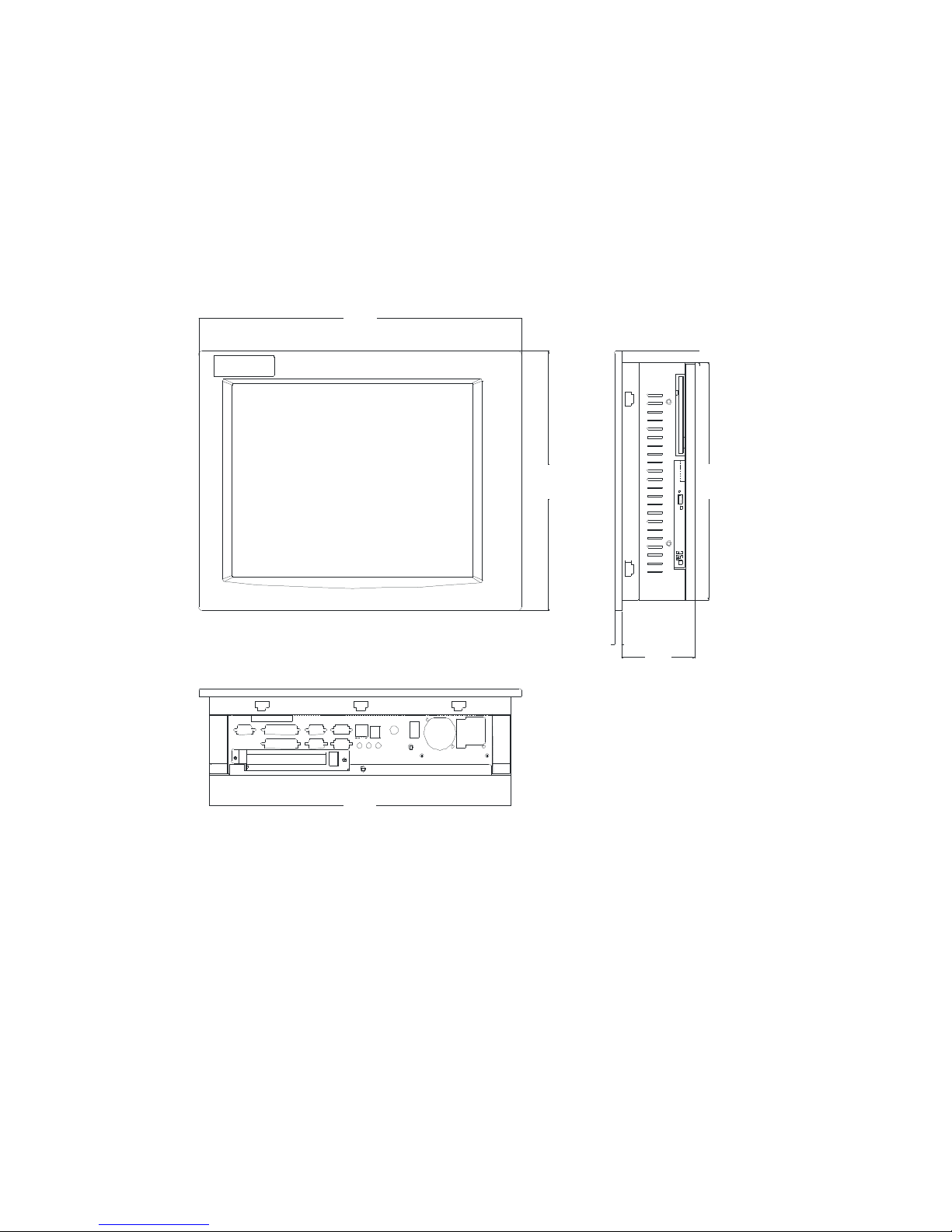
Mechanical Dimensions
Front Panel: 16.14” (410 mm) x 12.16” (309 mm) x 0.354” (9 mm) (WxHxD)
Cabinet: 15.1” (383.6 mm) x 11.13” (282.6 mm) x 3.68” (93.4 mm) (WxHxD)
Note: All dimensions in inches (mm
Figure 1–1. Unit Dimensions
5 141876(E)
)
Page 10
3115T Thin Line Industrial Flat Panel PC Chapter 2 – Installation
Chapter 2 — Installation
System Setup
The 3115T R3 Industrial Flat Panel PC is provided as a complete configured system
for your operation. The following sections of this chapter will help with installation
and maintenance.
Back Panel
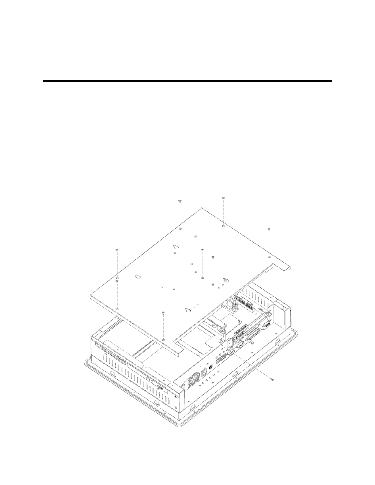
The diagram below shows the back panel of the 3115T R3. For maintenance,
installation or upgrade, first remove the back cover by unfastening seven screws as
shown in the diagram below.
Figure 2–1. System Back Panel
6 141876(E)
Page 11
3115T Thin Line Industrial Flat Panel PC Chapter 2 – Installation
Caution
Before any installation or un-installation, please take precautions
to prevent damage to the components due to static electricity.
I/O Panel
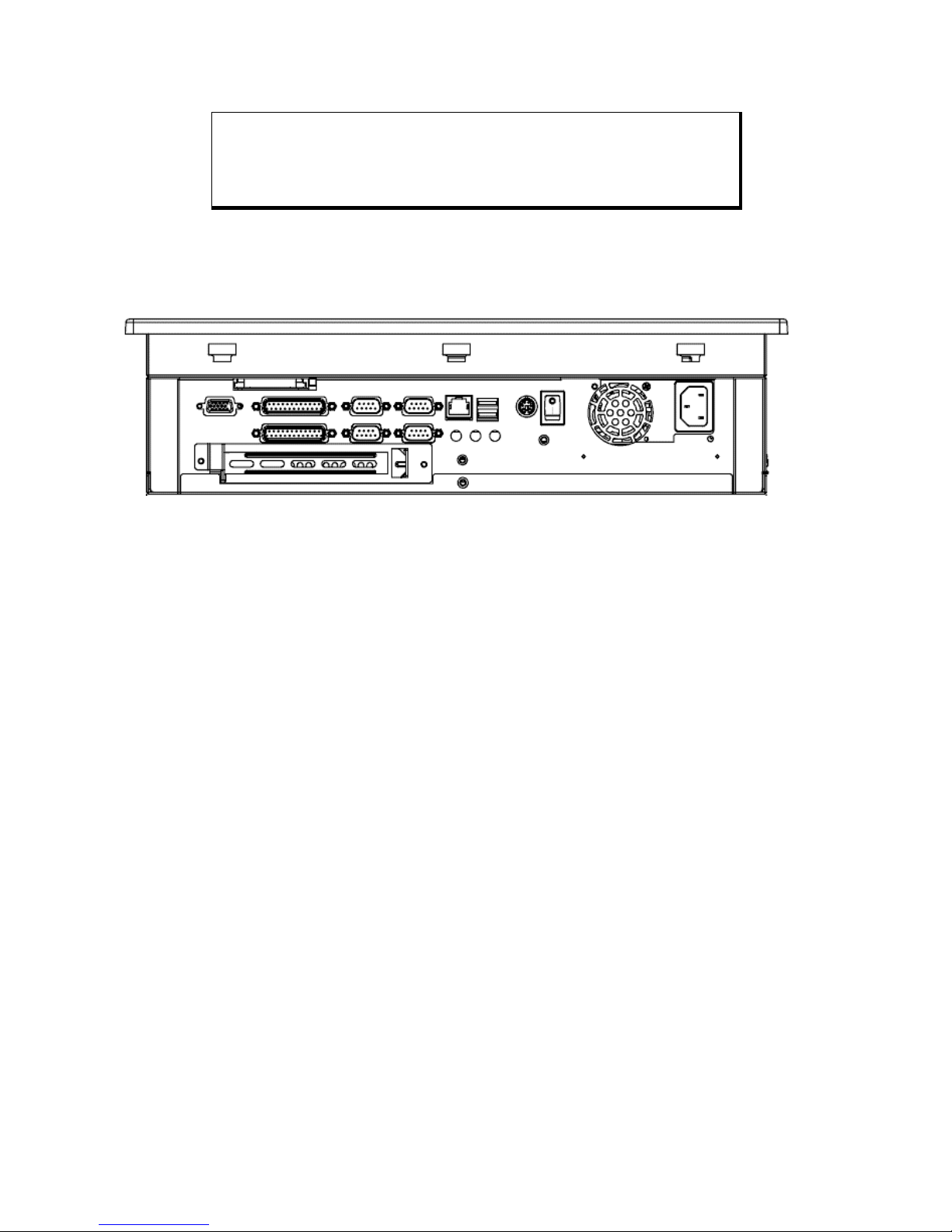
The figure below shows the I/O panel of the 3115T R3.
Figure 2–2. I/O Panel
7 141876(E)
Page 12
3115T Thin Line Industrial Flat Panel PC Chapter 2 – Installation
Front and Side Panels
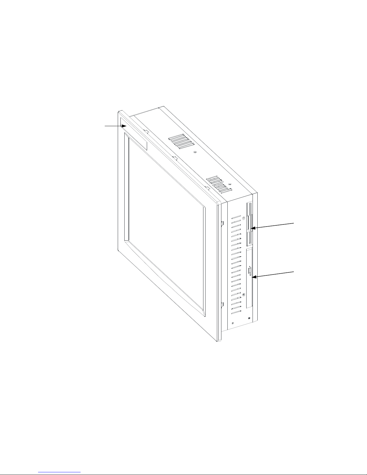
One Floppy Disk Drive and CD-ROM are accessible from the side of the chassis.
Logo
Figure 2–3. Front and Side Panel Views
Floppy Disk
Drive
CD-ROM
Drive
8 141876(E)
Page 13
3115T Thin Line Industrial Flat Panel PC Chapter 2 – Installation
Hard Disk Drive Installation/Removal
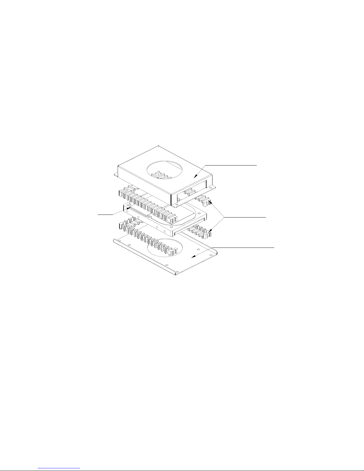
The following instructions tell how to install the hard disk drive (HDD):
1. Fasten the HDD to the HDD bracket.
2. Slide the HDD bracket into place, engaging the tabs. See figure 2–4.
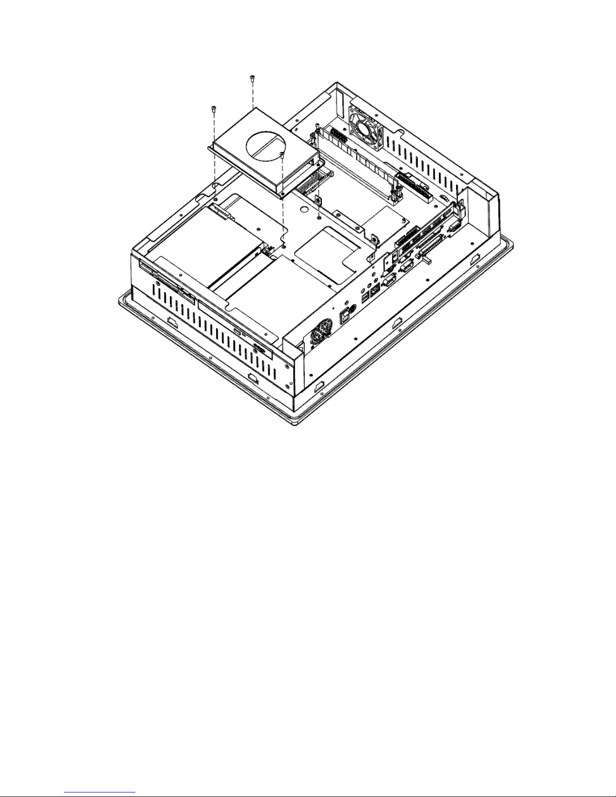
3. Fasten the HDD bracket to the cabinet using two screws. See figure 2–5.
HDD BRACKET TOP
HDD
MOUNT STRIPS
HDD BRACKET BOTTOM
Figure 2–4. HDD and HDD Bracket
9 141876(E)
Page 14
3115T Thin Line Industrial Flat Panel PC Chapter 2 – Installation
Figure 2–5. Installing HDD
10 141876(E)
Page 15
3115T Thin Line Industrial Flat Panel PC Chapter 2 – Installation
Mounting Options
The 3115T R3 can be mounted to a panel, to the wall, or to an arm. The following
sections describe each mounting option for the 3115T R3.
Panel Mounting
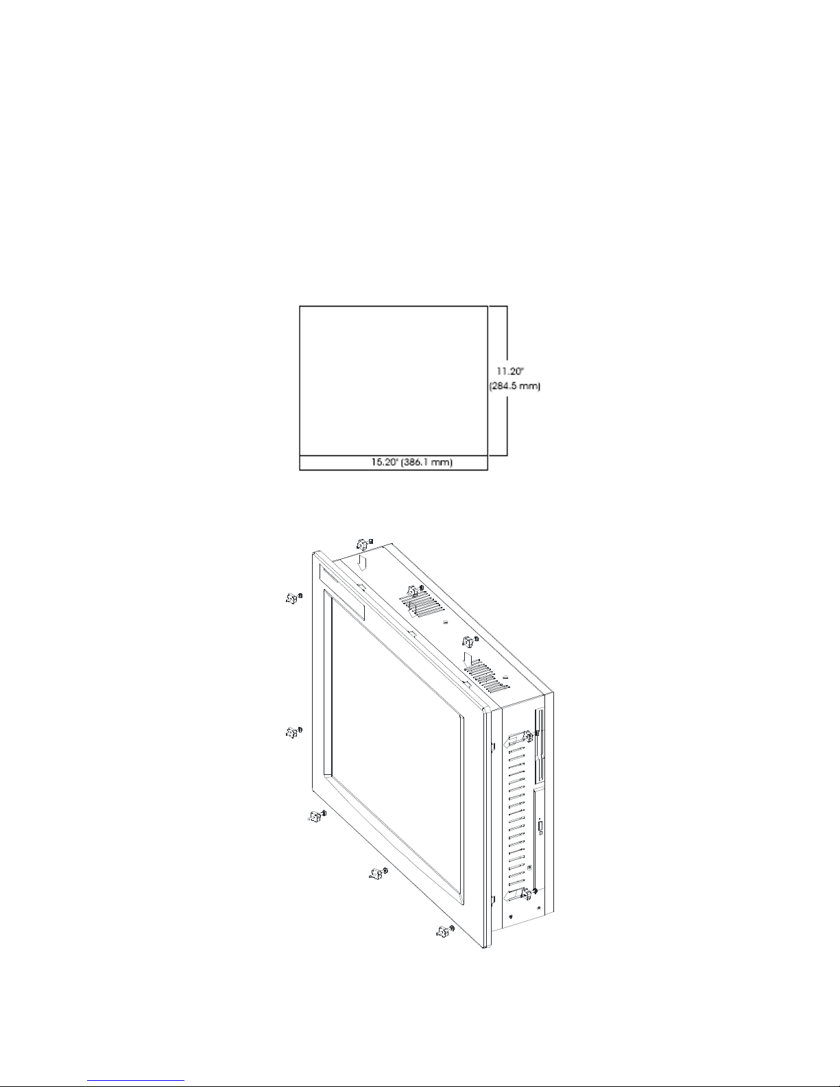
The 3115T R3 is designed for panel mounting. Before mounting the 3115T R3 to the
panel, check the cut out dimensions as shown in figure 2–6. Then, mount it to the
panel using ten supporters, as shown in the figure 2–7 below.
All dimensions in inches (mm)
Figure 2–6. Panel Cutout Dimensions
Figure 2–7. Panel Mounting
11 141876(E)
Page 16
3115T Thin Line Industrial Flat Panel PC Chapter 2 – Installation
Wall Mounting
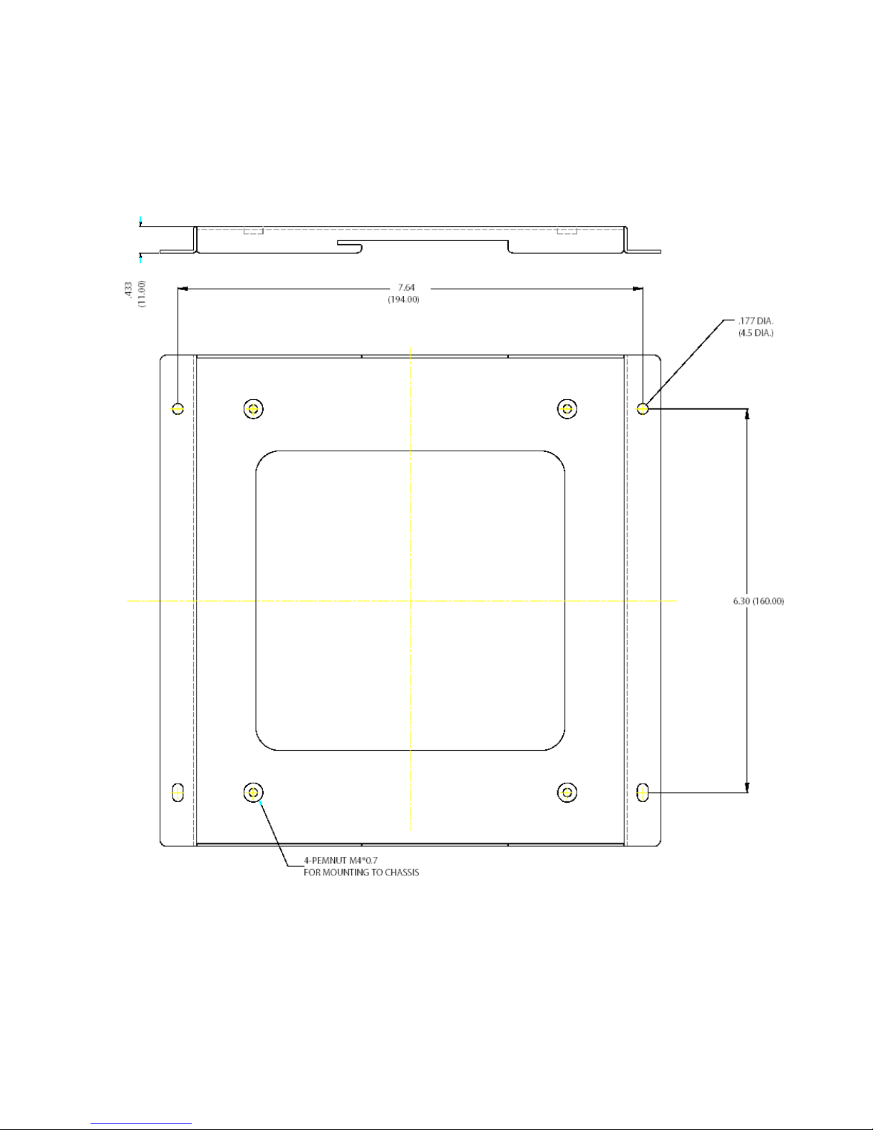
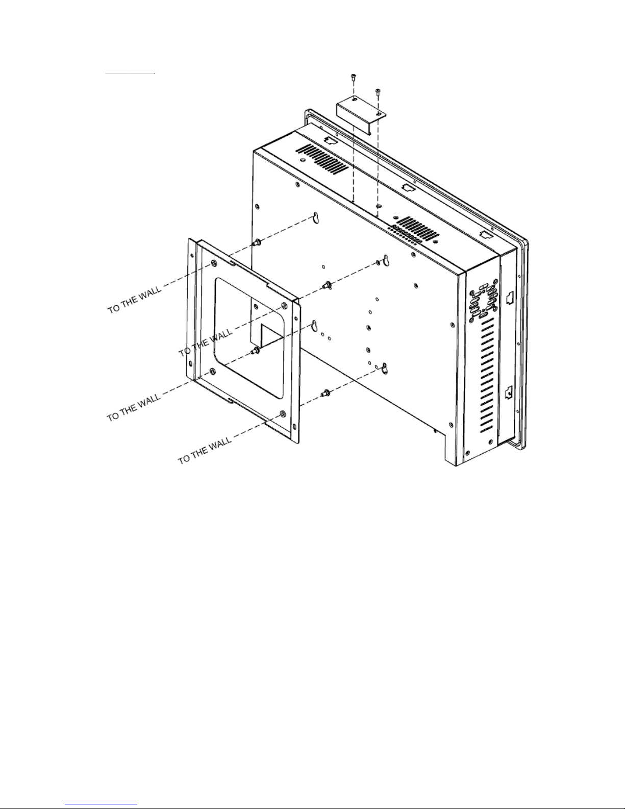
The 3115T R3 is suitable for wall mount using the included brackets and hardware.
See figure 2–8 for wall mounting dimensions. See figure 2–9 for a wall-mounting
diagram.
All dimensions are in inches (mm).
Figure 2–8. Wall Mount Dimensions
12 141876(E)
Page 17
3115T Thin Line Industrial Flat Panel PC Chapter 2 – Installation
Figure 2–9. Wall Mounting
13 141876(E)
Page 18
3115T Thin Line Industrial Flat Panel PC Chapter 2 – Installation
Arm Mounting
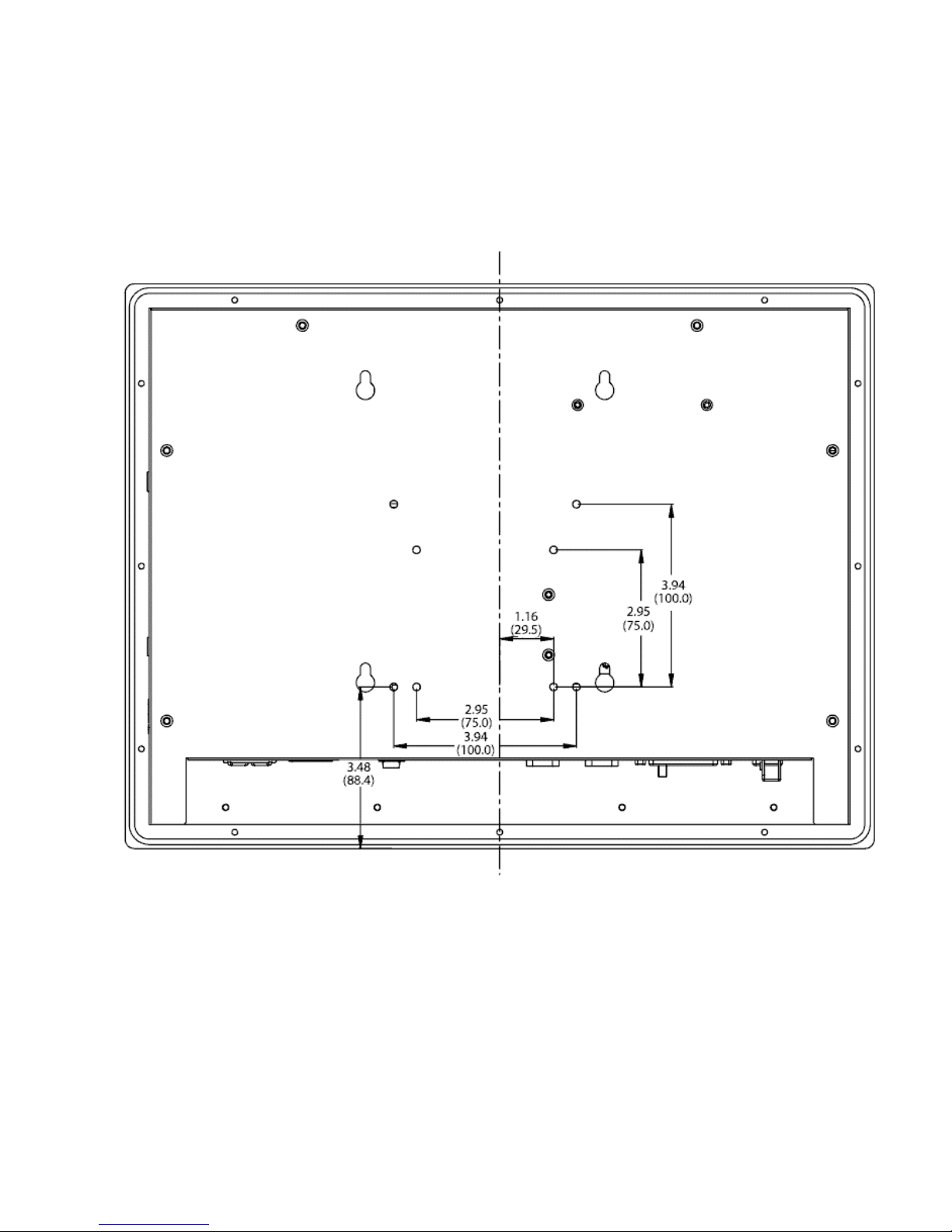
The 3115T R3 also accommodates 75/100 mm interface pads for arm mounting.
Figure 2–10 gives the dimensions for arm mounting.
All dimensions in inches (mm)
Figure 2–10. Arm Mounting Dimensions
14 141876(E)
Page 19

Chapter 3 – POS-370 Control Board and Award
BIOS Setup
POS-370N Multimedia POS Control Board
Product Overview
The 3115T R3 is equipped with a POS-370N Socket 370 Pentium III® (FC-PGA)
with Multimedia and a 10/100Mbps Ethernet embedded board. It is equipped with a
high-performance Celeron 1.2 GHz or Pentium III (FC-PGA) 1.26 GHz processor
and advanced high performance multi-mode I/O.
This board has a built-in IDE Interface CompactFlashDisk™ Flash Disk for
embedded application. The CompactFlashDisk™ Flash Disk is 100% compatible as
a hard disk drive, allowing users to run any DOS command without need of extra
software utility programs.
Two advanced high-performance LPC super I/O chips, the ITE (IT8705F) and NS
(NS87366), are used in the POS-370N board. The on-chip UARTs are compatible
with the NS16C550. The parallel port and FDD interface are compatible with IBM
PC/AT architecture.
POS-370N uses the advanced SIS, SIS630ST Chipset, which is 100% PCI
compatible chipset with PCI 2.1 standard. In addition, this board provides two 168pin sockets for its on-board DRAM. The DIMM module is a 3.3V SDRAM and
accommodates up to 512MB for each module.
Specifications
• CPU: Supports Celeron or Pentium III (FC-PGA) processor. Supports 133MHz FSB.
• Expansion Bus: PCI bus, expansion to support PCI bus signal
• DMA channels: 7
• Interrupt levels: 15
• Chipset: SIS630ST 66/100/133MHz CPU/DRAM Clock
• RAM: Two 168-pin DIMM sockets support SDRAM RAM module, up to 1GB.
• AGP VGA Controller: On chip SIS300 3D (Share memory up to 64MB RAM)
• 10/100Mbps Ethernet Controller: Intel 82559, Auto-sensing interface to 10Mbps,
100Mbps Network (RJ 45)
15 141876(E)
Page 20

3115T Thin Line Industrial Flat Panel PC Chapter 3 – POS-370 Control Board and BIOS Setup
• Ultra DMA/66 (Enhanced PCI IDE Interface): The Ultra DMA/66 IDE can handle
data transfer up to 66MB/second and is compatible with existing ATA-2 IDE
specifications.
• Three 16C550 RS-232C Ports (one used by the touch screen)
• One RS-232 or RS-422/485 Port (RS-485 features auto-direction control--no extra
direction control is needed).
• Two EPP/ECP parallel ports, one floppy port (three ports total external to the 3115T)
• Floppy disk drive
• Four high-speed Serial ports: NS16C550 compatible UARTs (three ports total
external to the 3115T, one used for the touch screen).
• Bi-directional parallel port
• IrDA port: Support First Infrared (FIR) and Amplitude Shift. Keyed IR(ASKIR)
interface internal to the 3115T.
• Two USB 1.1 ports
• Watchdog timer: Can be set to 1 minute (minimal) or above period. Reset is
generated when CPU does not periodically trigger the timer. Your program uses hex
440 to control the watchdog and generate a system reset.
• CompactFlash Disk™: The Flash Disk provides 100% compatibility with IDE hard
disk.
• Sound Blaster compatible audio chipset
• Wake-Up Function: Supports Wake-On-Lan and Wake-On-Ring.
• Mouse & Keyboard Connector: PS/2 Mouse Port Expansion Keyboard. (Requires Y-
adapter for both, external to the 3115T).
• Operating Humidity: 5 ~ 95 %, non-condensing
.
16 141876(E)
Page 21
3115T Thin Line Industrial Flat Panel PC Chapter 3 – POS-370 Control Board and BIOS Setup
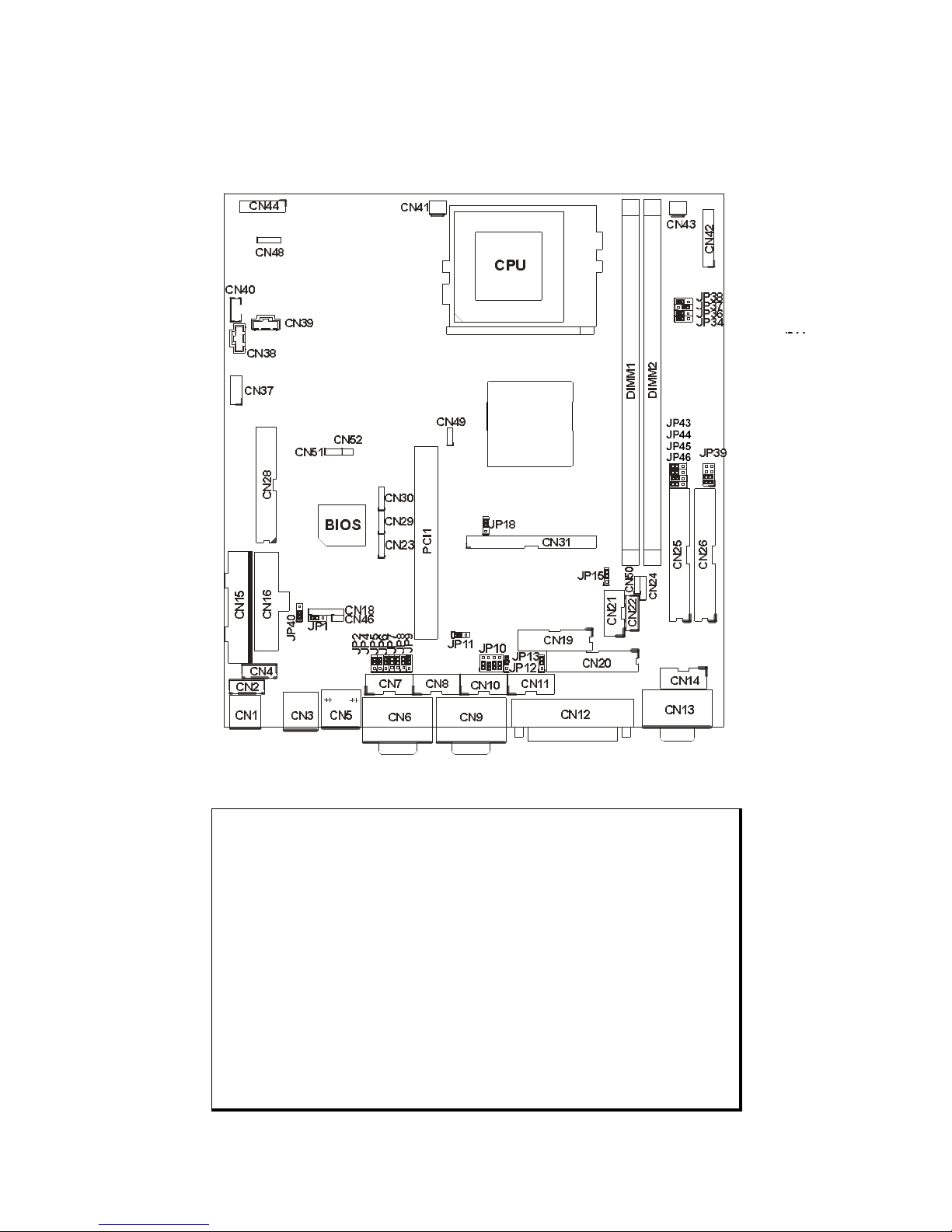
POS-370N CPU Board Layout
SIS630ST
Figure 3–1. POS-370N Board Layout
Caution
Some components on POS-370N are very sensitive to static discharges.
To protect it from unintended damage, be sure to follow these
precautions:
1. Ground yourself to remove any static charge before touching your
POS-370N. You can do it by using a grounded wrist strap at all times
or by frequently touching any conducting materials that is connected to
the ground.
2. Handle your POS-370N by its edges. Don’t touch IC chips, leads or
circuitry if not necessary.
3. Do not plug any connector or jumper while the power is on.
4. Do not put your POS-370N unprotected on a flat surface, as the board
has components on both sides.
17 141876(E)
Page 22

3115T Thin Line Industrial Flat Panel PC Chapter 3 – POS-370 Control Board and BIOS Setup
Jumper Settings
Setting the CPU of POS-370N
JP34,36,37,38: CPU & DRAM FREQUENCY SETTING (H/W)
Table 3–1. Settings for JP 34, 36, 37, and 38
CPU/DRAM JP34 JP36 JP37 JP38
66/66 2-3 2-3 2-3 1-2
100/100 1-2 1-2 2-3 1-2
133/133 1-2 1-2 1-2 2-3
JP39: CPU MULTIPLIER SETTING (AUTO)
Normally the CPU from Intel has fixed multipliers. In this case POS-370N will
automatically follow the CPU’s fixed multiplier settings no matter the JP39 jumper
setting.
Table 3–2. Settings for JP39
Ratio 1-2 3-4 5-6 7-8
3.0 x ON OFF OFF OFF
3.5 x ON OFF ON OFF
4.0 x OFF ON OFF OFF
4.5 x OFF ON ON OFF
5.0 x ON ON OFF OFF
5.5x ON ON ON OFF
6.0x OFF OFF OFF ON
6.5x OFF OFF ON ON
7x ON OFF OFF ON
7.5x OFF OFF ON ON
8x OFF ON OFF ON
CompactFlashDisk™ Flash Disk Setting
The CompactFlashDisk™ is 100% compatible to IDE hard disk. It is easy and
reliable “plug and play” technology. The CompactFlashDisk™ is available from
8MB to 128MB.
JP12: CompactFlashDisk™ IDE Master & Slave Setting
Pin No. Description
Open Slave
Short Master
18 141876(E)
Page 23
3115T Thin Line Industrial Flat Panel PC Chapter 3 – POS-370 Control Board and BIOS Setup
Clear CMOS Setup
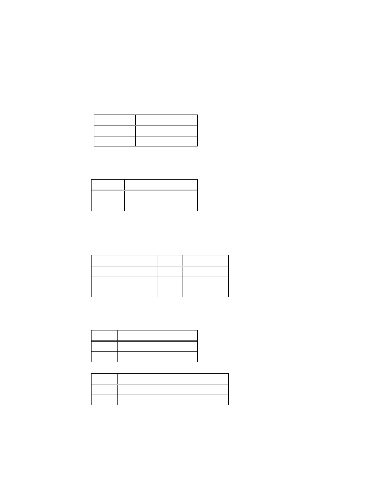
If you forget the CMOS password, you can clear or reset it by closing the JP18. After
JP18 (1-2) is closed, turn on the power for about 3 seconds then turn it off and open
the JP18 (1-2). After reboot, enter BIOS (DEL) and select “Load Optimized
Defaults”. Then select “Save and Exit”. Now the password has been cleared from
your CMOS.
JP18: Clear CMOS Setup
Pin No. Description
2-3 Normal Operation
1-2 Clear CMOS Setup
LCD Panel Power Setup
JP15: LCD Power Setting
JP15 Description
2-3 +3.3V
1-2* +5V
* Set to +5V is NOT standard
COM2 RS-232/422/485 Selection
JP10, JP11: COM2 Mode Selection
JP10 JP11 Description
1-2,4-5,7-8,10-11 1-2 RS232
2-3,5-6,8-9,11-12 2-3 RS422
2-3,5-6,8-9,11-12 2-3 RS485
COM Port RI and Voltage Selection
JP2, JP4: Set pin 9 of COM1 as signal RI or voltage source
JP2 Description
2-3 COM1 RI Pin Use RI
1-2 COM1 RI Pin Use Voltage
JP4 Description
2-3 COM1 RI Pin Use Voltage +12V
1-2 COM1 RI Pin Use Voltage +5V
* If JP2 Uses (2-3) Don’t care JP4
19 141876(E)
Page 24
3115T Thin Line Industrial Flat Panel PC Chapter 3 – POS-370 Control Board and BIOS Setup
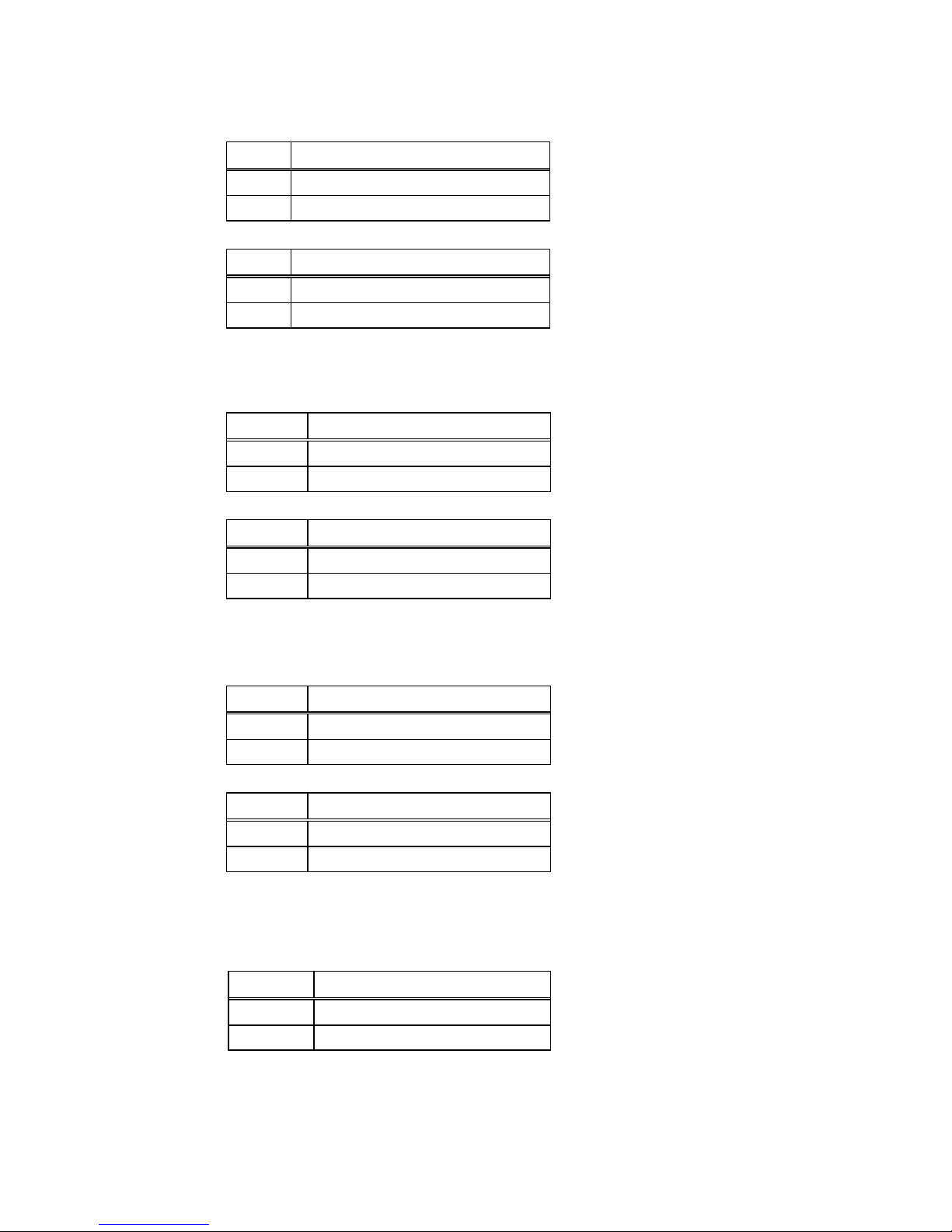
JP7, JP6: Set pin 9 of COM2 as signal RI or voltage source
JP7 Description
2-3 COM2 RI Pin Use RI
1-2 COM2 RI Pin Use Voltage
JP6 Description
2-3 COM2 RI Pin Use Voltage +12V
1-2 COM2 RI Pin Use Voltage +5V
* If JP7 Uses (2-3) Don’t care JP6
JP13, JP5: Set pin 9 of COM3 as signal RI or voltage source
JP13 Description
2-3 COM3 RI Pin Use RI
1-2 COM3RI Pin Use Voltage
JP5 Description
2-3 COM3 RI Pin Use Voltage +12V
1-2 COM3RI Pin Use Voltage +5V
* If JP13 Uses (2-3) Don’t care JP5
JP9,JP8: Set pin 9 of COM4 as signal RI or voltage source
JP9 Description
2-3 COM4 RI Pin Use RI
1-2 COM4RI Pin Use Voltage
JP8 Description
2-3 COM4 RI Pin Use Voltage +12V
1-2 COM4RI Pin Use Voltage +5V
* If JP9 Uses (2-3) Don’t care JP8
IR Power Selection
JP1: Select the operating voltage for IR (infrared)
JP1 Descripiton
1-2 VCC
2-3 5V Standby
20 141876(E)
Page 25

3115T Thin Line Industrial Flat Panel PC Chapter 3 – POS-370 Control Board and BIOS Setup
USB Power Selection
JP40: Select the operating voltage for USB
JP40 Description
1-2 VCC
2-3 5V Standby
Parallel Port
This port is usually connected to a printer. The POS-370N includes an on-board
parallel port, accessed through a 25-pin D-type female connector CN12 and 26-pin
flat-cable connector CN20.
LPT1: Parallel Port Connector (CN12)
Table 3–3. LPT1 Pinout
Pin No. Description Pin No. Description
1 STROBE# 2 DATA 0
3 DATA 1 4 DATA 2
5 DATA 3 6 DATA 4
7 DATA 5 8 DATA 6
9 DATA 7 10 ACKNOWLEDGE
11 BUSY 12 PAPER EMPTY
13 PRINTER SELECT 14 AUTO FORM FEED #
15 ERROR# 16 INITIALIZE
17 PRINTER SELECT LN# 18 GND
19 GND 20 GND
21 GND 22 GND
23 GND 24 GND
25 GND
21 141876(E)
Page 26
3115T Thin Line Industrial Flat Panel PC Chapter 3 – POS-370 Control Board and BIOS Setup
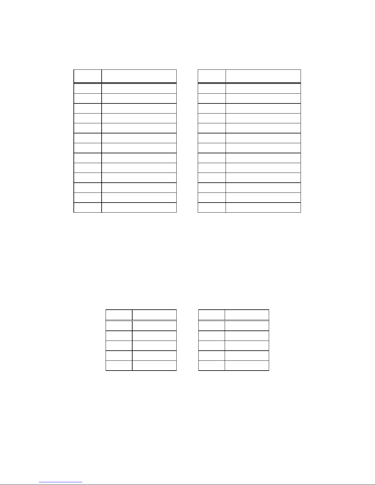
LPT2: Parallel Port Connector (CN20)
Table 3–4. LPT2 Pinout
Pin No. Description Pin No. Description
1 STROBE# 14 GND
2 AUTO FORM FEED # 15 DATA 6
3 DATA 0 16 GND
4 ERROR# 17 DATA 7
5 DATA 1 18 GND
6 INITIALIZE 19 ACKNOWLEDGE
7 DATA 2 20 GND
8 PRINTER SELECT LN# 21 BUSY
9 DATA 3 22 GND
10 GND 23 PAPER EMPTY
11 DATA 4 24 GND
12 GND 25 PRINTER SELECT
13 DATA 5 26 NC
Serial Ports
The POS-370N offers four high-speed NS16C550 compatible UARTs with
Read/Receive 16 byte FIFO serial ports (COM1/COM2/COM3/COM4).
COM1: Serial Port 2x5 pin header Connector (CN7)
Table 3–5. COM1 Pinout (CN7)
Pin No. Description Pin No. Description
1 DCD 6 CTX
2 DSR 7 DTR
3 RXD 8 RI
4 RTS 9 GND
5 TXD 10 NC
22 141876(E)
Page 27

3115T Thin Line Industrial Flat Panel PC Chapter 3 – POS-370 Control Board and BIOS Setup
COM1: Serial Port DB-9 Male Connector (CN6)
Table 3–6. COM1 Pinout (CN6)
Pin No. Description
1 DATA CARRIER DETECT (DCD)
2 RECEIVE DATA (RXD)
3 TRANSMIT DATA (TXD)
4 DATA TERMINAL READY (DTR)
5 GROUND (GND)
6 DATA SET READY (DSR)
7 REQUEST TO SEND (RTS)
8 CLEAR TO SEND (CTS)
9 RING INDICATOR (RI)
COM2: Serial Port 2x5 pin header Connector (CN10)
* COM2 supports three modes: RS232, RS422, RS485 (For 2x5 pin header Connector).
Table 3–7. COM2 Pinout (CN10)
Pin No. RS232 Mode RS422 Mode RS485 Mode
1 DCD TXD- RTX2 DSR RX- NC
3 RXD TXD+ RTX+
4 RTS RX+ NC
5 TXD NC NC
6 CTX NC NC
7 DTR NC NC
8 RI Voltage Voltage
9 GND NC NC
10 NC NC NC
23 141876(E)
Page 28
3115T Thin Line Industrial Flat Panel PC Chapter 3 – POS-370 Control Board and BIOS Setup
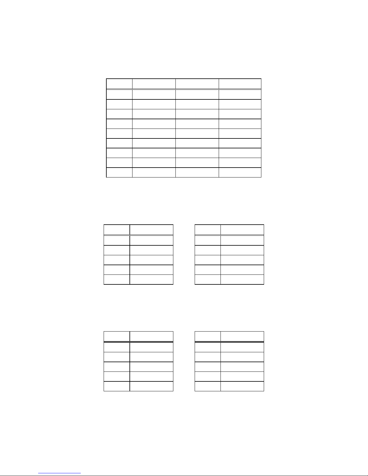
COM2: Serial Port DB-9 Male Connector (CN9)
* COM2 supports three modes: RS232, RS422, RS485 (For DB-9 Connector).
Table 3–8. COM2 Pinout (CN9)
Pin No. RS232 Mode RS422 Mode RS485 Mode
1 DCD TXD- RTX2 RXD TXD+ RTX+
3 TXD NC NC
4 DTR NC NC
5 GND NC NC
6 DSR RX- NC
7 RTS RX+ NC
8 CTX NC NC
9 RI Voltage Voltage
COM3: Serial Port 2x5 pin header Connector (CN11)
Table 3–9. COM3 Pinout (CN11)
Pin No. Description Pin No. Description
1 DCD 6 CTX
2 DSR 7 DTR
3 RXD 8 RI
4 RTS 9 GND
5 TXD 10 NC
COM4: Serial Port 2x5 pin header Connector (CN8)
Table 3–10. COM4 Pinout (CN8)
Pin No. Description Pin No. Description
1 DCD 6 CTX
2 DSR 7 DTR
3 RXD 8 RI
4 RTS 9 GND
5 TXD 10 NC
24 141876(E)
Page 29
3115T Thin Line Industrial Flat Panel PC Chapter 3 – POS-370 Control Board and BIOS Setup
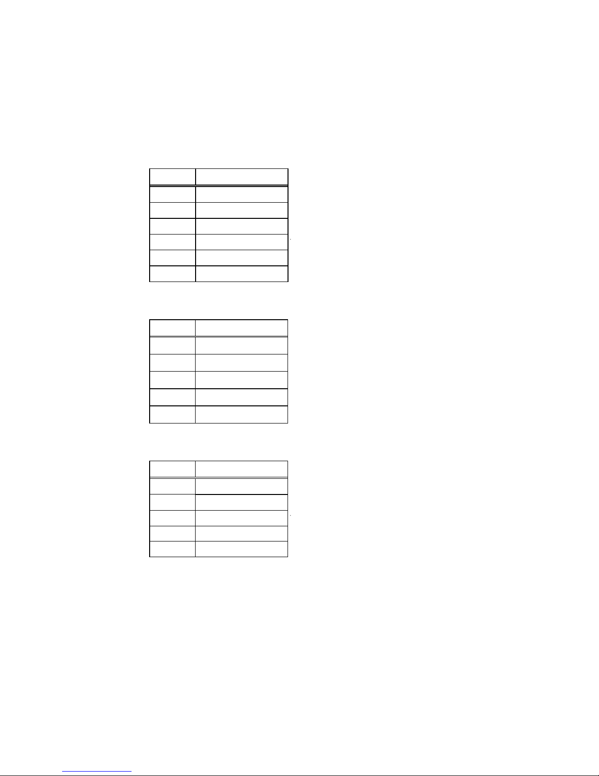
Keyboard/Mouse Connector
The POS-370N provides one external keyboard and mouse connector. A Y-adapter is
required to use both.
CN1: Extended Keyboard & PS/2 Mouse 6-pin Mini Din Connector
Pin No. Description
1 KB DATA
2 MS DATA
3 GND
4 VCC
5 KB CLOCK
6 MS CLOCK
CN4: 5-pin Header Keyboard Connector
Pin No. Description
1 KB CLOCK
2 KB DATA
3 N/C
4 GND
5 +5V
CN2: PS/2 Mouse 5-pin Header Connector
Pin No. Description
1 MS DATA
2 N/C
3 GND
4 +5V
5 MS CLOCK
25 141876(E)
Page 30
3115T Thin Line Industrial Flat Panel PC Chapter 3 – POS-370 Control Board and BIOS Setup
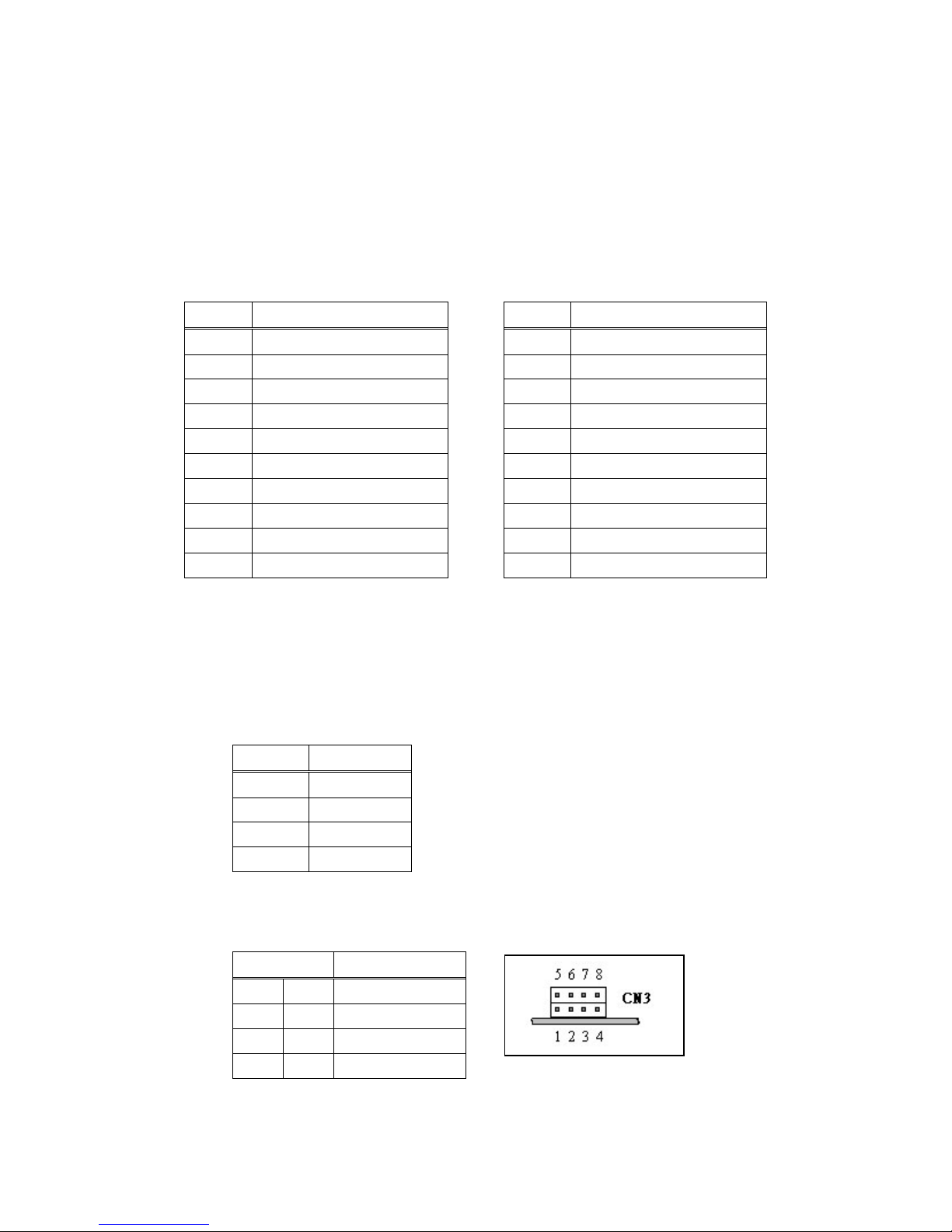
External Switches and Indicators
There are several external switches and indicators for monitoring and controlling
your CPU board. All the functions are in the CN42 connector.
CN42: Multi Panel
Table 3–11. External Switches and Indicators (CN42)
Pin No. Description Pin No. Description
1 SPEAKER 11 POWER-VCC
2 ACPI LED 12 N/C
3 N/C 13 GND
4 +5V 14 KEYLOCK
5 RESET SW 15 GND
6 GND 16 GND
7 IDE LED - 17 N/C
8 IDE LED+ 18 ATX POWER CONTROL
9 ATX POWER BUTTON 19 ATX 5VSB
10 GND 20 ATX 5VSB
USB Port Connector
The POS-370N has five built-in USB ports for the future new I/O bus expansion.
CN23, 29, 30: Pin Header USB Connector
Pin No. Description
1 VCC
2 USBD03 USBD0+
4 GND
CN3: 2 External USB Connectors
Pin No. Description
1 5 VCC
2 6 USBD03 7 USBD0+
4 8 GND
26 141876(E)
Page 31
3115T Thin Line Industrial Flat Panel PC Chapter 3 – POS-370 Control Board and BIOS Setup
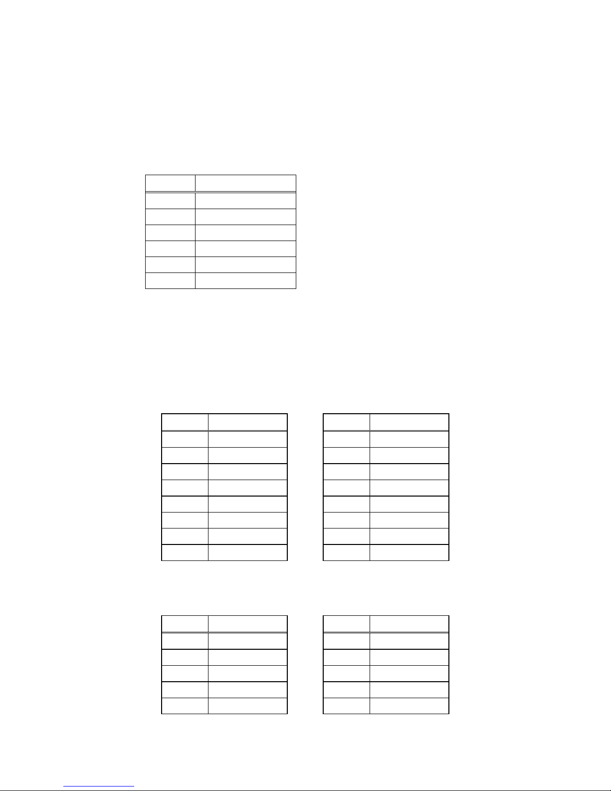
IrDA Infrared Interface Port
POS-370N built-in IrDA port supports Serial Infrared (SIR) or Amplitude Shift
Keyed IR (ASKIR) interface. If you want to use the IrDA port, you have to configure
the FIR or ASKIR model in the BIOS’s Peripheral Setup’s COM2. The normal RS232 COM2 will be disabled.
CN18: IrDA Connector
Pin No. Description
1 VCC
2 CIR-TX
3 IR-RX
4 GND
5 IR-TX
6 CIR-RX
* Pin 2, 6 Support CIR
VGA Connector
The built-in 10-pin VGA connector can be connected directly to your monochrome
CRT monitor as well as high-resolution color CRT monitor.
CN13: 15-pin Female VGA Connector
Table 3–12. VGA Connector Pinout (CN13)
Pin No. Description Pin No. Description
1 RED 9 VCC
2 GREEN 10 GND
3 BLUE 11 NC
4 NC 12 DDC DAT
5 GND 13 HSYNC
6 GND 14 VSYNC
7 GND 15 DDC CLK
8 GND
CN14: 10-pin Connector
Table 3–13. VGA Connector Pinout (CN14)
Pin No. Description Pin No. Description
1 RED 6 GND
2 SMCLK 7 H-SYNC
3 GREEN 8 GND
4 SMDATA 9 V-SYNC
5 BLUE 10 GND
27 141876(E)
Page 32
3115T Thin Line Industrial Flat Panel PC Chapter 3 – POS-370 Control Board and BIOS Setup
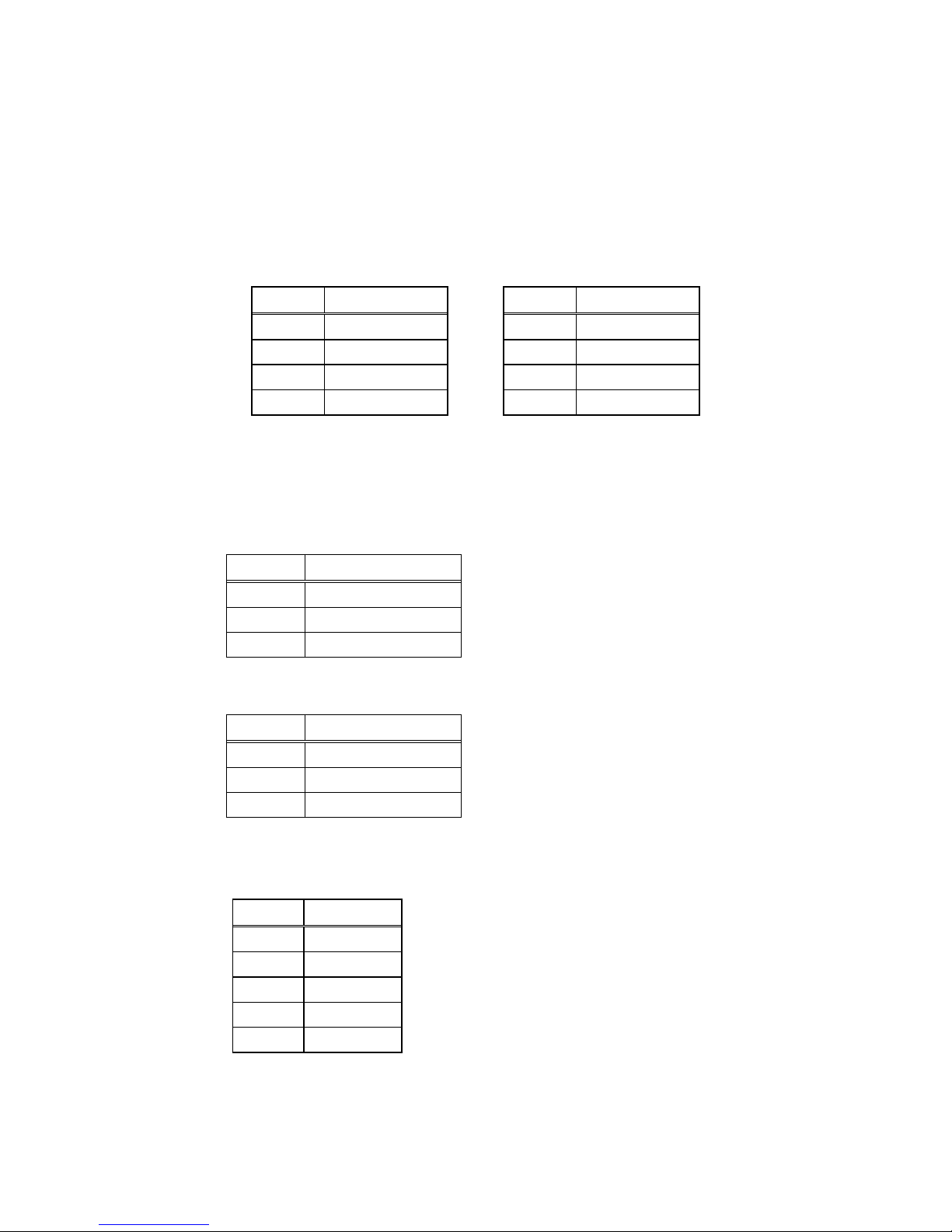
LAN RJ45 Connector
POS-370N is equipped with an Intel 82559 10/100Mbps Ethernet Controller. You
can connect it to your LAN through RJ45 LAN connector. The pin assignments are
as follows.
CN5: LAN 1 RJ45 Connector
Table 3–14. LAN RJ45 Connector (CN5)
Pin No. Description Pin No. Description
1 TX+ 5 N/C
2 TX- 6 RX3 RX+ 7 N/C
4 N/C 8 N/C
Fan Connector
The POS-370N provides one CPU cooling fan connector and one-system fan
connectors. These connectors can supply 12V/500mA to the cooling fan.
CN41: CPU Fan Connector
Pin No. Description
1 Fan Sensor
2 +12V
3 GND
CN43: System Fan Connector
Pin No. Description
1 Fan Sensor
2 +12V
3 GND
LCD Backlight Connector
CN22: LCD Backlight Connector
Pin No. Description
1 NC
2 ENABKL
3 GND
4 +12V
5 GND
28 141876(E)
Page 33
3115T Thin Line Industrial Flat Panel PC Chapter 3 – POS-370 Control Board and BIOS Setup
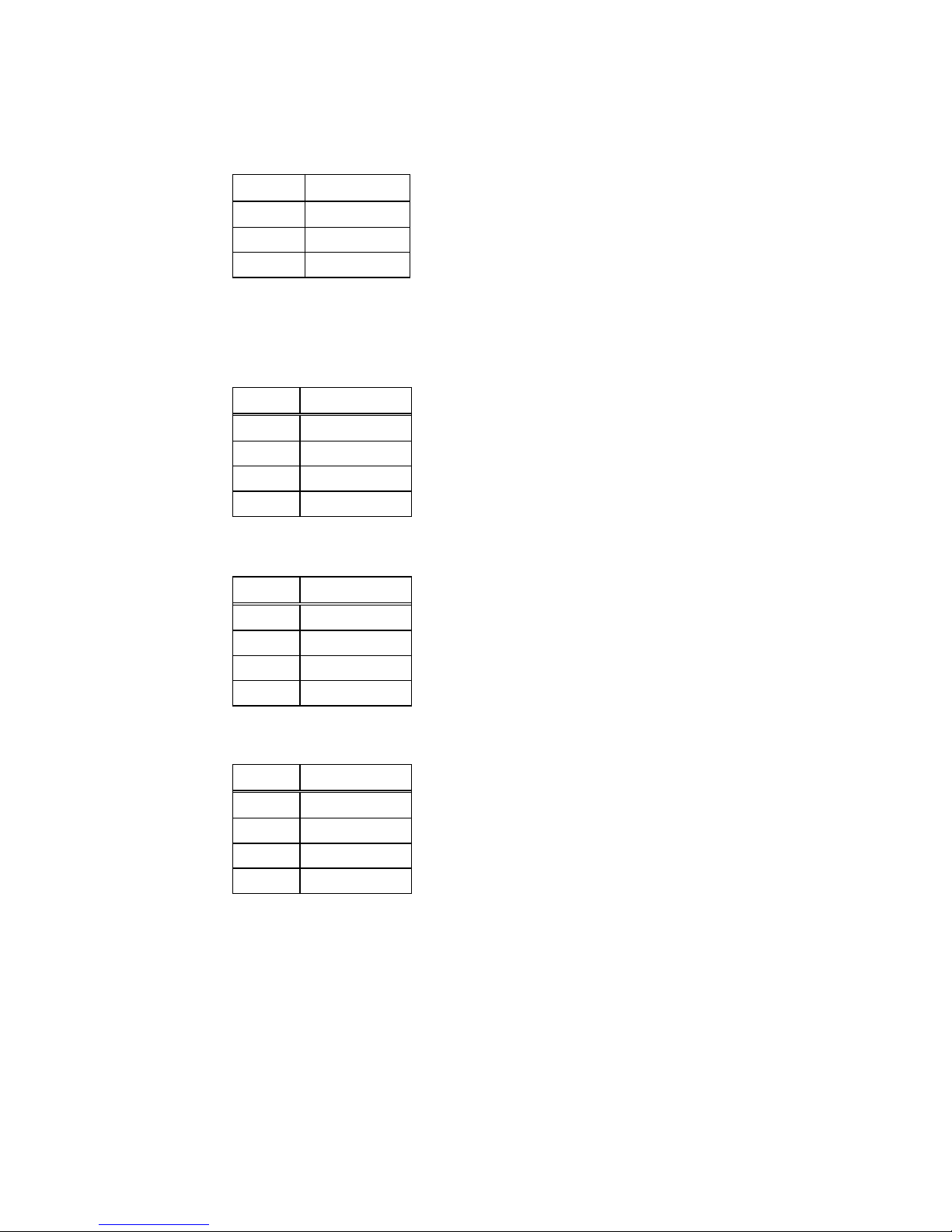
Home Networking Connector (Optional)
CN49: Home Networking Connector
Pin No. Description
1 HRXP
2 GND
3 HRXN
* Need Transformer Board
Audio Line IN
CN40: Audio CD IN (2.0mm)
Pin No. Description
1 CD IN_R
2 GND
3 CD IN_L
4 GND
CN38: Audio Video IN (2.54mm)
Pin No. Description
1 CD IN_R
2 GND
3 GND
4 CD IN_L
CN39: Audio AUX IN (2.54mm)
Pin No. Description
1 CD IN_R
2 GND
3 GND
4 CD IN_L
29 141876(E)
Page 34
3115T Thin Line Industrial Flat Panel PC Chapter 3 – POS-370 Control Board and BIOS Setup
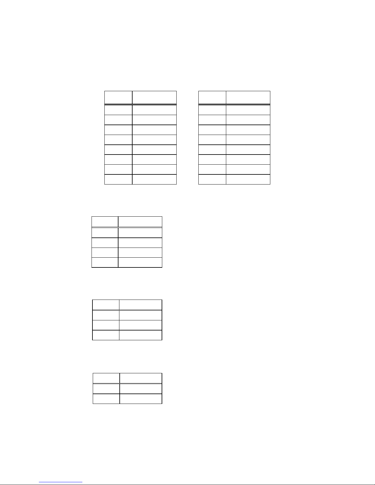
Audio Panel
CN44: Audio Panel
Table 3–15. Audio Panel Pinout (CN44)
Pin No. Description Pin No. Description
1 Line Out R 9 Line In R
2 GND 10 Line In L
3 Line Out L 11 GND
4 GND 12 GND
5 Line Out R 13 SPK Out R
6 Line Out L 14 SPK Out L
7 GND 15 MIC In
8 GND 16 GND
Audio SPK Output Connector
CN48: Audio SPK Output Connector
Pin No. Description
1 SPK-R
2 GND
3 GND
4 SPK-L
Chassis Intrusion Detection Connector
CN51: Chassis Intrusion Detection Input Connector
Pin No. Description
1 Pull_High
2 CHAS_IN
3 GND
* Need Pin 1 and Pin 2 short Active
CN52: Chassis Intrusion Detection Output Connector
Pin No. Description
1 CHAS_OUT
2 5VSB
* Normal Pin 1 High
* Active Pin 1 Always Low (If JP41 Pin 2 short to Pin 1)
30 141876(E)
Page 35

3115T Thin Line Industrial Flat Panel PC Chapter 3 – POS-370 Control Board and BIOS Setup
User Mode OSD Feature
The 3115T R3 has user mode on screen display (OSD) adjustment controls. The
following table describes each function of the OSD controls.
Table 3–16. User Mode OSD Feature
Feature Description
Auto-Adjustment This feature will automatically adjust the H/V position, frequency,
phase, and black level.
Auto Phase This feature will automatically adjust the sampling.
Brightness This function will adjust the offset value of ADC. Setting this value too
high or too low will decrease the quality of images.
Contrast This option is used to adjust the contrast level on the screen and will
adjust the gain value of ADC. Adjusting this value too high or too low
will decrease the quality of images.
DOS/GFX This option is used to select the VGA input signal in either text or
graphic mode. (This option is only available on resolutions of
720/640x400 or 720/640x350). Standard IBM modes 350 and 400
have the same Hsync. and Vsync. Values. The display control circuit
cannot differentiate between the Hsync. And Vsync. values
automatically, so the user should adjust them manually to match the
proper VGA mode .
H. Position This option is used to adjust horizontal display position of image.
V. Position This option is used to adjust vertical display position of image.
Language This option is used to select the language used on the OSD display.
The display control circuit can support 2 languages on the OSD
display. English is the default language.
Revert This option is used to reset the original parameters to the factory’s
OSD data area of the system EEPROM (24c16) device. When the
user over-adjusts the OSD data and sees no improvement in the
quality, then the user can select this feature and the display control
circuit will reload default BIOS setting and re-initialize the system.
Save This option is used to save the parameters into the EEPROM
(24c16) system’s user OSD adjustment data area and close the
OSD. Whenever the user adjusts any parameters, this option will
save the changed data on to the EEPROM (24c16) so that the MPU
will use the stored data to initialize the display control circuit system
on future re-boots.
Main Menu Each level of the OSD has an item named Main Menu, which allows
the user to exit the current level and return to the main menu.
Exit Press the EXIT key to exit the OSD menu when you are finished.
31 141876(E)
Page 36

3115T Thin Line Industrial Flat Panel PC Chapter 3 – POS-370 Control Board and BIOS Setup
Award BIOS Setup
This section describes the Award Setup program built into the ROM BIOS. The
setup program allows users to modify the basic system configuration. This special
information is then stored in battery-backed RAM so that it retains the Setup
information when the power is turned off.
Starting Setup
The Award BIOS is immediately activated when you first power on the computer.
The BIOS reads the system information contained in the CMOS and begins the
process of checking out the system and configuring it. When it finishes, the BIOS
will seek an operating system on one of the disks and then launch and turn control
over to the operating system.
While the BIOS is in control, the Setup program can be activated in one of two ways:
1. By pressing <Del> immediately after switching the system on, or
2. By pressing the <Del> key when the following message appears briefly at the
bottom of the screen during the POST (Power On Self Test).
Press DEL to enter SETUP.
If the message disappears before you respond and you still wish to enter Setup,
restart the system to try again by turning it OFF then ON or pressing the "RESET"
button on the system case. You may also restart by simultaneously pressing <Ctrl>,
<Alt>, and <Delete> keys. If you do not press the keys at the correct time and the
system does not boot, an error message will be displayed and you will again be asked
to...
PRESS F1 TO CONTINUE, DEL TO ENTER SETUP
32 141876(E)
Page 37

3115T Thin Line Industrial Flat Panel PC Chapter 3 – POS-370 Control Board and BIOS Setup
Using Setup
In general, you use the arrow keys to highlight items, press Enter to select, use the
PgUp and PgDn keys to change entries, press F1 for help and press Esc to quit. The
following table provides more detail about how to navigate in the Setup program
using the keyboard.
Table 3–17. Using Setup
Up arrow Move to previous item
Down arrow Move to next item
Left arrow Move to the item in the left hand
Right arrow Move to the item in the right hand
Esc key Main Menu -- Quit and not save changes into CMOS
Status Page Setup Menu and Option Page Setup
Menu -- Exit current page and return to Main Menu
PgUp key Increase the numeric value or make changes
PgDn key Decrease the numeric value or make changes
+ key Increase the numeric value or make changes
- key Decrease the numeric value or make changes
F1 key General help, only for Status Page Setup Menu and
Option Page Setup Menu
F4 key Reserved
F5 key Restore the previous CMOS value from CMOS, only
for Option Page Setup Menu
F6 key Load the default CMOS value from BIOS default
table, only for Option Page Setup Menu
F7 key Load the optimized default CMOS value
F8 key Reserved
F9 key Reserved
F10 key Save all the CMOS changes, only for Main Menu
Getting Help
Press F1 to pop up a small help window that describes the appropriate keys to use
and the possible selections for the highlighted item. To exit the Help Window press
Esc or the F1 key again.
If, after making and saving system changes with Setup, you discover that your
computer no longer is able to boot, the Award BIOS supports an override to the
CMOS settings, which resets your system to its defaults.
The best advice is to only alter settings that you thoroughly understand. To this end,
we strongly recommend that you avoid making any changes to the chipset defaults.
These defaults have been carefully chosen by both Award and your systems
manufacturer to provide the absolute maximum performance and reliability. Even a
33 141876(E)
Page 38

3115T Thin Line Industrial Flat Panel PC Chapter 3 – POS-370 Control Board and BIOS Setup
seemingly small change to the chipset setup has the potential for causing you to use
the override.
Main Menu
Once you enter the AwardBIOS™ CMOS Setup Utility, the Main Menu will appear
on the screen. The Main Menu allows you to select from several setup functions and
two exit choices. Use the arrow keys to select among the items and press Enter to
accept and enter the sub-menu.
Standard CMOS Feature
Advanced BIOS Feature
Advanced Chipset Feature
Integrated Peripherals
PnP/PCI Configurations
PC Health Status
Esc: Quit
↑ ↓ ← →: Select Item
F10: Save & Exit Setup
Time, Date, Hard Disk Type….
Figure 3–2. CMOS Setup Utility
Frequency/Voltage Control
Load Fail-Safe Defaults
Load Optimized Defaults
Set Password
Save & Exit Setup
Exit Without Saving
Note: A brief description of each highlighted selection appears at the bottom of the
screen.
The main menu includes the main setup categories listed in table 3–18. Note that
some systems may not include all entries.
34 141876(E)
Page 39

3115T Thin Line Industrial Flat Panel PC Chapter 3 – POS-370 Control Board and BIOS Setup
Main Menu Selections
Table 3–18. Main Menu Selections
Item Options Description
Date MM DD YYYY Set the system date.
Time HH: MM: SS Set the system time
IDE
Primary Master
IDE
Primary Slave
IDE
Secondary Master
IDE
Secondary Master
Drive A
Drive B
LCD&CRT Both Select LCD & CRT Display
Panel Hardware Setting
Halt On All Errors
Base Memory N/A Displays the amount of
Extended Memory N/A Displays the amount of extended
Total Memory N/A Displays the total memory
Options are in its sub menu
(described in Table 3)
Options are in its sub menu
(described in Table 3)
Options are in its sub menu
(described in Table 3)
Options are in its sub menu
(described in Table 3)
None
360K, 5.25 in
1.2M, 5.25 in
720K, 3.5 in
1.44M, 3.5 in
2.88M, 3.5 in
800x600 TFT1
800x600 TFT2
1024x768 18bit TFT1
1024x768 18bit TFT2
1024x768 18bit TFT3
1024x768 18bit TFT4
1024x768 24bit TFT
No Errors
All, but Keyboard
All, but Diskette
All, but Disk/Key
Press Enter to enter the sub
menu of detailed options
Press Enter to enter the sub
menu of detailed options
Press Enter to enter the sub
menu of detailed options
Press Enter to enter the sub
menu of detailed options
Select the type of floppy disk
drive installed in your system
Select Panel Type. Every type is
predefined with a special timing.
You may try each setting
according to your LCD. However,
not every kind of LCD will be
supported.
Select the situation in which you
want the BIOS to stop the POST
process and notify you
conventional memory detected
during boot up
memory detected during boot up
available in the system
35 141876(E)
Page 40

3115T Thin Line Industrial Flat Panel PC Chapter 3 – POS-370 Control Board and BIOS Setup
None
None
safe defaults
F10:Save
Standard CMOS Setup
The items in Standard CMOS Setup Menu are divided into 10 categories. Each
category includes no, one or more than one setup items. Use the arrow keys to
highlight the item and then use the PgUp or PgDn keys to select the value you want
in each item.
Standard CMOS Features
Date: Mon, Feb 8 1999
Time: 16:19:20
IDE Primary Master 2557 MB
IDE Primary Slave
IDE Secondary Master None
IDE Secondary Slave
Drive A 1.44M, 3.5 in.
Drive B None
LCD&CRT Both
Panel Hardware Setting
Halt On All Errors
Based Memory 640K
Extended Memory 64512K
Item Help
Menu Level
Change the day, month, year
and century
Total Memory 65536K
↑↓ ← → Move F1:General Help
Enter: Select F5: Previous Values
+/-/PU/PD: Value F6: Fail ESC: Exit F7:Optimized Defaults
Figure 3–3. Standard CMOS Features
36 141876(E)
Page 41

3115T Thin Line Industrial Flat Panel PC Chapter 3 – POS-370 Control Board and BIOS Setup
IDE Adapters
The IDE adapters control the hard disk drive. Use the legend keys to navigate
through this menu and exit to the main menu. Use Table 3–19 to configure the hard
disk.
IDE Primary Master
IDE HDD Auto-Detection Press Enter
IDE Primary Master Auto 2557 MB
Access Mode Auto
Capacity xxx MB
Cylinder 4956
Head 16
Precomp 0
Landing Zone 4955
Sector 63
↑↓ ← → Move F1:General Help
Enter: Select F5:Previous Values
+/-/PU/PD: Value F6:Fail-safe defaults
ESC: Exit F7:Optimized Defaults
F10:Save
Figure 3–4. CMOS Setup Utility
Menu Level
To auto-detect the HDD’s
size, head... on this
channel
Item Help
37 141876(E)
Page 42

3115T Thin Line Industrial Flat Panel PC Chapter 3 – POS-370 Control Board and BIOS Setup
Table 3–19. Hard Disk selections
Item Options Description
IDE HDD Auto-detection Press Enter Press Enter to auto-detect the HDD on
this channel. If detection is successful, it
fills the remaining fields on this menu.
IDE Primary Master None
Auto
Manual
Selecting ‘manual’ lets you set the
remaining fields on this screen. Selects
the type of fixed disk. "User Type" will let
you select the number of cylinders,
heads, etc. Note: PRECOMP=65535
means NONE!
Capacity Auto Display your disk
drive size
Disk drive capacity (Approximated). Note
that this size is usually slightly greater
than the size of a formatted disk given by
a disk checking program.
Access Mode Normal
LBA
Choose the access mode for this hard
disk
Large
Auto
The following options are selectable only if the ‘IDE Primary Master’ item is set to ‘Manual’
Cylinder Min = 0
Max = 65535
Head Min = 0
Set the number of cylinders for this hard
disk.
Set the number of read/write heads
Max = 255
Precomp Min = 0
Max = 65535
Landing zone Min = 0
**** Warning: Setting a value of 65535
means no hard disk
****
Max = 65535
Sector Min = 0
Number of sectors per track
Max = 255
38 141876(E)
Page 43
3115T Thin Line Industrial Flat Panel PC Chapter 3 – POS-370 Control Board and BIOS Setup
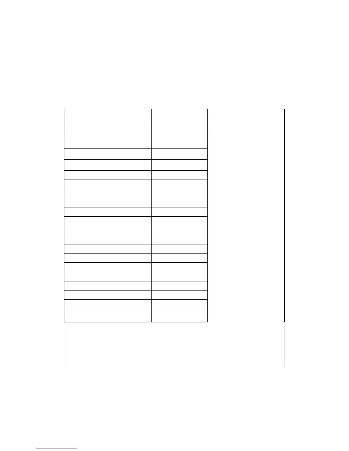
Advanced BIOS Features
This section allows you to configure your system for basic operation. You have the
opportunity to select the system’s default speed, boot-up sequence, keyboard
operation, shadowing and security.
Advanced BIOS Features
Virus Warning Enabled
CPU Internal Cache Enabled
External Cache Enabled
CPU L2 Cache ECC Checking Enabled
Processor Number Feature Enabled
Quick Power On Self Test Disabled
First Boot device Floppy
Second Boot device HDD-0
Third Boot device Floppy
Boot other device Disabled
Onboard LAN Boot ROM Disabled
Swap Floppy Drive Disabled
Boot Up Floppy Seek Disabled
Boot Up NumLock Status Off
Gate A20 Option Normal
Typematic Rate Setting Disabled
Typematic Rate (Chars/Sec) 6
Typematic Delay (Msec) 250
Security Option Setup
OS Select For DRAM > 64MB Non-OS2
Report NO FDD For Win 95 No
Item Help
Menu Level
Allows you to choose the
VIRUS warning feature for
IDE Hard Disk boot sector
protection. If this function is
enabled and someone
attempt to write data into this
area, BIOS will show a
warning message on screen
and alarm beep
Video BIOS Shadow Enabled
↑↓ ← → Move F1:General Help
Enter: Select F5:Previous Values
+/-/PU/PD: Value F6:Fail-safe defaults
ESC: Exit F7:Optimized Defaults
F10:Save
Figure 3–5. CMOS Setup Utility
39 141876(E)
Page 44
3115T Thin Line Industrial Flat Panel PC Chapter 3 – POS-370 Control Board and BIOS Setup
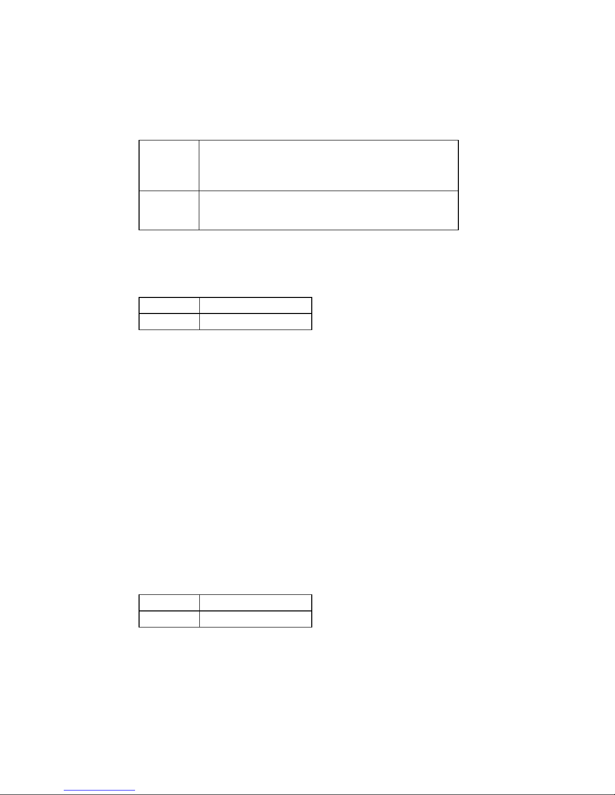
Virus Warning
This allows you to choose the VIRUS Warning feature for IDE Hard Disk boot
sector protection. If this function is enabled and someone attempts to write data into
this area, the BIOS will show a warning message on screen and the alarm will beep.
Enabled Activates automatically when the system boots up
causing a warning message to appear when anything
attempts to access the boot sector or hard disk partition
table.
Disabled No warning message will appear when anything
attempts to access the boot sector or hard disk partition
table.
CPU Internal Cache/External Cache
These two categories speed up memory access. However, it depends on CPU/chipset
design.
Enabled Enable cache
Disabled Disable cache
CPU L2 Cache ECC Checking
This item allows you to enable/disable CPU L2 Cache ECC checking.
The choice: Enabled, Disabled.
Processor Number Feature
Some of the new generations of socket-370N processors are installed with a unique
processor number. This number may be used for verification in Internet transactions
and e-commerce. If you prefer not to use or distribute the unique processor number,
use this item to suppress the processor number.
The choice: Enable, Disable.
Quick Power On Self Test
This category speeds up Power On Self Test (POST) after you power up the
computer. If it is set to Enable, BIOS will shorten or skip some check items during
POST. If set to Enable, the BIOS will skip memory check.
Enabled Enable quick POST
Disabled Normal POST
First/Second/Third/Other Boot Device
The BIOS attempts to load the operating system from the devices in the sequence
selected of these items.
The choices: Floppy, LS/ZIP, HDD, SCSI, CDROM, Disabled
40 141876(E)
Page 45

3115T Thin Line Industrial Flat Panel PC Chapter 3 – POS-370 Control Board and BIOS Setup
Note
If “other” boot option is enabled, the unit will boot from the
CompactFlash (if the CF card has boot files loaded).
Swap Floppy Drive
If the system has two floppy drives, you can swap the logical drive name
assignments.
The choice: Enabled/Disabled.
Boot Up Floppy Seek
Seeks disk drives during boot up. Disabling speeds boot up.
The choice: Enabled/Disabled.
Boot Up NumLock Status
Select power on state for NumLock.
The choice: Enabled/Disabled.
Gate A20 Option
Select if chipset or keyboard controller should control GateA20.
Normal A pin in the keyboard controller controls
GateA20
Fast Lets chipset control GateA20
Typematic Rate Setting
Keystrokes repeat at a rate determined by the keyboard controller. When enabled, the
typematic rate and typematic delay can be selected.
The choice: Enabled/Disabled.
Typematic Rate (Chars/Sec)
The Typematic rate sets the number of times a second keystroke is repeated when the
key is held down.
The choice: 6, 8, 10, 12, 15, 20, 24, 30.
Typematic Delay (Msec)
The Typematic delay sets the delay time after the key is held down before it begins
to repeat the keystroke.
The choice: 250, 500, 750, 1000.
41 141876(E)
Page 46
3115T Thin Line Industrial Flat Panel PC Chapter 3 – POS-370 Control Board and BIOS Setup
Security Option
Select whether the password is required every time the system boots or only when
you enter setup.
System The system will not boot and access to Setup will be
denied if the correct password is not entered at the prompt.
Setup The system will boot, but access to Setup will be denied if
the correct password is not entered at the prompt.
Note
To disable security, select PASSWORD SETTING at Main Menu and then you
will be asked to enter password. Do not type anything and just press Enter, it
will disable security. Once the security is disabled, the system will boot and you
can enter
Setup freely.
OS Select For DRAM > 64MB
Select the operating system that is running with greater than 64MB of RAM on the
system.
The choice: Non-OS2, OS2.
Report No FDD For Win 95
Whether report no FDD for Win 95 or do report FDD for Win 95.
The choice: Yes, No.
Video BIOS Shadow
This item allows the video BIOS to be copied to system memory for faster
performance.
The choice: Enable, Disable.
42 141876(E)
Page 47

3115T Thin Line Industrial Flat Panel PC Chapter 3 – POS-370 Control Board and BIOS Setup
Advanced Chipset Features
Advanced Chipset Features
Advanced DRAM Control 1 Press Enter
Advanced DRAM Control 2 Press Enter
System BIOS Cacheable Disabled
Video BIOS Cacheable Disabled
Memory Hole At 15M-16M Enabled
AGP Aperture Size 64MB
Graphic Window WR Combin Enabled
Concurrent function (MEM) Enabled
Concurrent function (PCI) Enabled
CPU Pipeline Control Enabled
PCI Delay Transaction Enabled
Menu Level
Item Help
Power-supply Type AT
Memory Parity Check Enabled
↑↓ ← → Move F1:General Help
Enter: Select F5:Previous Values
+/-/PU/PD: Value F6:Fail-safe defaults
ESC: Exit F7:Optimized Defaults
F10:Save
Figure 3–6. CMOS Setup Utility
This section allows you to configure the system based on the specific features of the
installed chipset. This chipset manages bus speeds and access to system memory
resources, such as DRAM and the external cache. It also coordinates
communications between the conventional ISA bus and the PCI bus. It must be stated
that these items should never need to be altered. The default settings have been
chosen because they provide the best operating conditions for your system.
Advanced DRAM Control 1/2 Settings
The first chipset settings deal with CPU access to dynamic random access memory
(DRAM). The default timings have been carefully chosen and should only be altered
if data is being lost. Such a scenario might well occur if your system had mixed
speed DRAM chips installed so that greater delays may be required to preserve the
integrity of the data held in the slower memory chips.
43 141876(E)
Page 48

3115T Thin Line Industrial Flat Panel PC Chapter 3 – POS-370 Control Board and BIOS Setup
Table 3–20. Advanced DRAM Control ½ Settings
Setting Description
Auto Configuration This item will automatically configure the chipset timing. Select ‘Manual’
to enter a specific timing value.
The choice: Manual, Auto, 100MHZ, 133MHZ.
SDRAM RAS Active Time This item defines SDRAM ACT to PRE command period.
The choice: 6T, 7T, 5T, 4T.
SDRAM RAS Pre-charge Time This item defines SDRAM PRE to ACT command period.
The choice: 3T, 2T, 4T, Reserved.
RAS to CAS Delay This item defines SDRAM ACT to Read/Write command period.
The choice: 3T, 2T, 4T, Reserved.
DRAM Background Command This item is lead-off time control for DRAM background command.
When 'Delay 1T' is selected, background commands are issued one
clock after the memory address (MA) command has been issued. When
'Normal' is selected, background commands and MA are issued at the
same time.
The choice: Delay 1T, Normal.
LD-Off DRAM RD/WR Cycles The item is lead-off time control for DRAM Read/Write Cycles. When
'Delay 1T' is selected, the memory read/write command is issued one
clock pulse after the memory address (MA) is issued. When 'Normal' is
selected, the read/write command and MA are issued at the same time.
The choice: Delay 1T, Normal.
Write Recovery Time This item defines the Data-in to PRE command period.
The choice: 1T, 2T
VCM REF To ACT/REF Delay This item defines VCM REF to REF/ACT command period. The
choice: 10T, 9T.
VCM ACCT To ACT/REF Delay This item defines VCM ACT to ACT/REF command period.
The choice: 10T, 9T, 8T, Reserved.
Early CKE Delay 1T Cntrl When this item is enabled, CKE is driven out from flip-flop. It is used
when system operates under low frequency and CKE delay adjustment
method defined in the 'Early CKE Delay Adjust' setting, which cannot
meet the setup time and hold time requirements.
The choice: Normal, Delay 1T.
Early CKE Delay Adjust This item controls the timing for CKE. Various delay options are
provided to ensure that CKE can meet the SDRAM setup time and hold
time specification when CKE is driven out.
The choice: 1ns, 2ns, 3ns, 4ns, 5ns, 6ns, 7ns, 8ns.
Mem Command Output Time This item is to control the timing to drive memory command onto
memory bus.
The choice: Normal, Delay 1T.
SDRAM/VCM CAS Latency When synchronous DRAM is installed, the number of clock cycles of
CAS latency depends on the DRAM timing.
The choice: 2, 3, SPD
SDRCLK Control This item controls the phase of SDRCLK that lags behind SDCLK.
The choice: Enabled, Disabled.
44 141876(E)
Page 49
3115T Thin Line Industrial Flat Panel PC Chapter 3 – POS-370 Control Board and BIOS Setup
Setting Description
SDWCLK Control CS#/CKE This item controls the phase of SDWCLK used for chip set select
signals pin that lags ahead SDCLK.
The choice: Enabled, Disabled.
SDWCLK Control MA/SRAS This item controls the phase of SDWCLK used for MA/ SRAS signals
that lags ahead SDCLK.
The choice: +5.0ns~-2.5ns (Default 0.0ns)
SDWCLK Control DQM/MD This item controls the phase of SDWCLK used for DQM/MD signals that
lags ahead SDCLK. The choice: +5.0ns~-2.5ns (Default 0.0ns)
EGMRCLK Control This item controls the phase of EGMRCLK that lags behind SDCLK.
The choice: -1.0ns~+6.5ns (Default 0.0ns)
EGMWCLK Control This item controls the phase of EGMWCLK that lags ahead SDCLK.
The choice: +5.0ns~-2.5ns (Default 0.0ns)
System BIOS Cacheable
Selecting ‘Enabled’ allows caching of the system BIOS ROM at F0000h-FFFFFh,
resulting in better system performance. However, if any program writes to this
memory area, a system error may result.
The choice: Enabled, Disabled.
Video RAM Cacheable
Selecting ‘Enabled’ allows caching of the video RAM, resulting in better system
performance. However, if any program writes to this memory area, a system error
may result.
The choice: Enabled, Disabled.
Memory Hole at 15M-16M
You can reserve this area of system memory for ISA adapter ROM. When this area is
reserved, it cannot be cached. The user information of peripherals that need to use
this area of system memory usually discusses their memory requirements.
The choice: Enabled, Disabled.
AGP Aperture Size
This item allows you to select the size of Accelerated Graphics Port (AGP) aperture.
The aperture is a portion of the PCI memory address range dedicated for graphics
memory address space. Host cycles that hit the aperture range are forwarded to the
AGP without any translation.
The choice: 4M, 8M, 16M, 32M, 64M, 128M, 256M.
45 141876(E)
Page 50

3115T Thin Line Industrial Flat Panel PC Chapter 3 – POS-370 Control Board and BIOS Setup
Graphic Window WR Combin
Use this item to enable or disable CPU support for WR Combin.
The choice: Enable, Disable
Concurrent Function (MEM)
This item allows you to set the CPU & PCI Masters Concurrently Access Memory
Function. Selecting ‘Enabled’ allows CPU access memory cycles and PCI masters
access memory cycles to be concurrently issued onto host bus and PCI bus,
respectively. The memory access cycles will be rearranged by SIS630 to write to
memory sequentially.
The choice: Enabled, Disabled
Concurrent Function (PCI)
This item allows you to set the CPU & PCI Masters Concurrently Access PCI Bus
Function. Selecting ‘Enabled’ allows CPU access PCI bus cycle and PCI masters
access memory cycles to be concurrently issued onto host bus and PCI bus,
respectively.
The choice: Enabled, Disabled.
CPU Pipeline Control
When this item is enabled, only one pending cycle is allowed at one time.
When this item is disabled, there might be more than two pending cycles at one time
depends on the CPU behavior.
The choice: Enabled, Disabled.
PCI Delay Transaction
If the chipset has an embedded 32-bit write buffer to support delay transaction
cycles, you can enable this item to provide compliance with PCI Ver.2.1
specifications. We recommend that you leave this item at the default value.
The choice: Enable, Disable.
Power-Supply Type
This item controls the power-supply type to AT or ATX.
The choice: AT, ATX.
Memory Parity Check
Enabled this item to test the boot-up memory.
The choice: Enabled, Disabled.
46 141876(E)
Page 51

3115T Thin Line Industrial Flat Panel PC Chapter 3 – POS-370 Control Board and BIOS Setup
Integrated Peripherals
Integrated Peripherals
SIS 630 OnChip IDE Device Press Enter
SIS 630 OnChip PCI Device Press Enter
Super I/O Device Press Enter
USB Controller Enabled
USB Keyboard Support Enabled
Init Display First PCI Slot
IDE HDD Block Mode Enabled
System Share Memory 8MB
↑↓←→ Move Enter: Select +/-/PU/PD: Value F10: Save ESC: Exit F1: General Help
F5: Previous Values F6:Fail-safe defaults F7:Optimized Defaults
Figure 3–7. CMOS Setup Utility
Item Help
__________________________
_________
Menu Level
If your IDE hard drive supports
block mode select Enabled for
automatic detection of the
optimal number of block
read/write per sector the drive
can support
SIS 630 OnChip IDE Device
Internal PCI/IDE
This chipset contains an internal PCI IDE interface with support for two IDE
channels.
The choice: Primary, Secondary, Both.
IDE Primary Master/Slave PIO
The four IDE PIO (Programmed Input/Output) fields let you set a PIO mode (0-4) for
each of the four IDE devices that the onboard IDE interface supports. Modes 0
through 4 provide successively increased performance. In ‘Auto’ mode, the system
automatically determines the best mode for each device.
The choice: Auto, Mode 0, Mode 1, Mode 2, Mode 3, and Mode 4.
Primary Master/Slave UltraDMA
UDMA (Ultra DMA) is a DMA data transfer protocol that utilizes ATA commands
and the ATA bus to allow DMA commands to transfer data at a maximum burst rate
of 33 MB/s. When you select Auto in the four IDE UDMA fields (for each of up to
four IDE devices that the internal PCI IDE interface supports), the system
automatically determines the optimal data transfer rate for each IDE device.
The choice: Auto, Disabled.
47 141876(E)
Page 52

3115T Thin Line Industrial Flat Panel PC Chapter 3 – POS-370 Control Board and BIOS Setup
IDE Burst Mode
Selecting ‘Enabled’ reduces latency between each drive read/write cycle, but may
cause instability in IDE subsystems that cannot support such fast performance. If you
are getting disk drive errors, try setting this value to ‘Disabled’. This field does not
appear when the Internal PCI/IDE field, above, is ‘Disabled’.
The choice: Enabled, Disabled.
SIS 630 OnChip PCI Device
SIS-7018 AC97 AUDIO
Select ‘Enabled’ to support AC97 Audio.
The choice: Enabled, Disabled.
Onboard FDC Controller
Select ‘Enabled’ if your system has a floppy disk controller (FDC) installed on the
system board and you wish to use it. If you install and-in FDC or the system has no
floppy drive, select ‘Disabled’ in this field.
The choice: Enabled, Disabled.
Onboard Serial Port 1/ Port 2/Port 3/Port 4
Select an address and corresponding interrupt for the first and second serial ports.
The choice: 3F8/IRQ4, 2E8/IRQ3, 3E8/IRQ4, 2F8/IRQ3, Disabled, Auto.
UART Mode Select
This item allows you to select UART mode.
The choice: Enabled, Disabled.
UR3 Duplex Mode
This item allows you to select the IR half/full duplex function.
The choice: Half, Full.
Onboard Parallel Port 1/Port 2
This item allows you to determine access onboard parallel port controller with which
I/O address.
The choice: 3BC/IRQ7, 378/IRQ7, 278/IRQ5, Disabled.
48 141876(E)
Page 53

3115T Thin Line Industrial Flat Panel PC Chapter 3 – POS-370 Control Board and BIOS Setup
Parallel Port Mode
Select an operating mode for the onboard parallel (printer) port. Select ‘Normal’,
‘Compatible’, or ‘SPP’ unless you are certain your hardware and software both
support one of the other available modes.
The choice: SPP, EPP, ECP, ECP+EPP.
ECP Mode Use DMA
Select a DMA channel for the parallel port for use during ECP mode.
The choice: 3, 1.
USB Controller
Select ‘Enabled’ if your system contains a Universal Serial Bus (USB) controller and
you have USB peripherals.
Choices are: Enabled, Disabled.
USB Keyboard Support
Select ‘Enabled’ if your system contains a Universal Serial Bus (USB) controller and
you have a USB keyboard.
Choices are: Enabled, Disabled.
IDE HDD Block Mode
Block mode is also called block transfer, multiple commands, or multiple sector
read/write. If your IDE hard drive supports block mode (most new drives do), select
‘Enabled’ for automatic detection of the optimal number of block read/writes per
sector the drive can support.
The choice: Enabled, Disabled.
Init Display First
This item allows you to decide to active which bus first (PCI Slot or AGP first).
The choice: PCI Slot, AGP.
System Share Memory Size
This item defines the System Share Memory Size for video.
The choice:2MB, 4MB, 16MB, 32MB, 64MB, 2+2MB, 4+4MB,
8+8MB,16+16MB,32+32MB.
49 141876(E)
Page 54

3115T Thin Line Industrial Flat Panel PC Chapter 3 – POS-370 Control Board and BIOS Setup
Power Management Setup
The Power Management Setup allows you to configure you system to most
effectively save energy while operating in a manner consistent with your own style
of computer use.
Power Management Setup
ACPI function Enabled
Item Help
ACPI Suspend Type S3 (STR)
Video Off Option Susp,Stby -> Off
Video Off Method V/H SYNC_Blank
Switch Function Break/Wake
Hot Key Function As Power Off
HDD Off After Disable
Power Button Override Instant Off
KB Power On Password Disable
PM Wake Up Events Press Enter
Power Up by Alarm Press Enter
↑↓←→Move Enter: Select +/-/PU/PD: Value F10:Save ESC: Exit F1:General Help
F5: Previous Values F6:Fail-safe defaults F7:Optimized Defaults
Figure 3–8. CMOS Setup Utility
____________________________
_______
Menu Level
ACPI Function
This item allows you to enable/disable the Advanced Configuration and Power
Management (ACPI).
The choice: Enabled, Disabled.
ACPI Suspend Type
This item allows you to S1 (Power ON Suspend)/S3 (Suspend To RAM) the
Advanced Configuration and Power Management (ACPI).
The choice: S1 (POS), S3 (STR).
50 141876(E)
Page 55
3115T Thin Line Industrial Flat Panel PC Chapter 3 – POS-370 Control Board and BIOS Setup
Video Off Option
When enabled, this feature allows the VGA adapter to operate in a power saving
mode.
Always on Monitor will remain on during power saving modes.
SuspendOff Monitor blanked when the systems enters the Suspend
mode.
Susp.Stby Off Monitor blanked when the system enters either Suspend or
Standby modes
All Modes Monitor blanked when the system enters any power saving
mode.
Video Off Method
This determines the manner in which the monitor is blanked.
V/H
SYNC+Blank
Blank Screen This option only writes blanks to the video buffer.
DPMS Select this option if your monitor supports the Display Power
This selection will cause the system to turn off the vertical and horizontal
synchronization ports and write blanks to the video buffer.
Management Signaling (DPMS) standard of the Video Electronics
Standards to select video power management values.
Switch Function
You can choose whether or not to permit your system to enter complete Suspend
mode. Suspend mode offers greater power savings, with a correspondingly longer
awakening period..
The choice: Break/Wake, Disabled.
Hot Key Function As
Select ‘Enabled’ if your system has a hot key for soft power off.
The choice: Enabled, Disabled.
HDD Off After
By default, this item is disabled, meaning that no matter the mode the rest of the
system, the hard drive will remain ready. Otherwise, you have a range of choices
from 1 to 15 minutes or ‘Suspend’. This means that you can elect to have your hard
disk drive be turned off after a selected number of minutes or when the rest of the
system goes into a Suspend mode.
Power Button Over Ride
You could press the power button for more than four seconds forces the system to
enter the Soft-Off state when the system has “hung.”
The choice: Soft-Off, Delay 4 Sec.
51 141876(E)
Page 56

3115T Thin Line Industrial Flat Panel PC Chapter 3 – POS-370 Control Board and BIOS Setup
PM Wake Up Events
IRQ [3-7,9-15], NMI
The following is a list of IRQ’s, Interrupt ReQuests, which can be exempted much as
the COM ports and LPT ports above can. When an I/O device wants to gain the
attention of the operating system, it signals this by causing an IRQ to occur. When
the operating system is ready to respond to the request, it interrupts itself and
performs the service.
As above, the choices are On and Off.
When set to ‘On’, activity will neither prevent the system from going into a power
management mode nor awaken it.
IRQ [ 3-7, 9-15], NMI
IRQ 8 Break Suspend: You can ‘Enable’ or ‘Disable’ monitoring of IRQ8 (the Real
Time Clock) so it does not awaken the system from Suspend mode.
Ring/PCIPME Power Up Control
When you select ‘Enabled’, a signal from ring/PCIPME returns the system to Full
On state.
The choice: Enabled, Disabled.
KB Power On Password
This item can be used to prompt the used for a password when the system power is
resumed by keyboard action.
The choice: Disable, Enable.
Power Up by Alarm
When you select ‘Enabled’, the following fields appear. They let you set the alarm
that returns the system to Full On state.
Date (of Month) Alarm lets you select a day from 1 to 31. Time Alarm lets you select
a time for the alarm in hours, minutes, and seconds.
The choice: Enabled, Disabled.
52 141876(E)
Page 57

3115T Thin Line Industrial Flat Panel PC Chapter 3 – POS-370 Control Board and BIOS Setup
PnP/PCI Configuration Setup
This section describes configuring the PCI bus system. PCI, or Personal Computer
Interconnect, is a system that allows I/O devices to operate at speeds nearing the
speed of the CPU itself uses when communicating with its own special components.
This section covers some very technical items and it is strongly recommended that
only experienced users should make any changes to the default settings.
PnP/PCI Configurations
Item Help
Reset Configuration Data Disabled
Resources Controlled By Auto (ESCD)
IRQ Resources Press Enter
PCI/VGA Palette Snoop Disabled
↑↓←→Move Enter: Select +/-/PU/PD: Value F10:Save ESC: Exit F1:General Help
F5: Previous Values F6: Fail-safe defaults F7:Optimized Defaults
Figure 3–9. CMOS Setup Utility
------------------------Menu Level
Default is Disabled. Select
Enabled to reset Extended
System Configuration Data
(ESCD) when you exit
Setup if you have installed a
new add-on and the system
reconfiguration has caused
such a serious conflict that
the OS cannot boot
Reset Configuration Data
Normally, you leave this field Disabled. Select Enabled to reset Extended System
Configuration Data (ESCD) when you exit Setup if you have installed a new add-on
and the system reconfiguration has caused such a serious conflict that the operating
system cannot boot.
The choice: Enabled, Disabled.
Resource controlled by
The Award Plug and Play BIOS has the capacity to automatically configure all of the
boot and Plug and Play compatible devices. However, this capability means
absolutely nothing unless you are using a Plug and Play operating system such as
Windows95. If you set this field to “manual” choose specific resources by going
into each of the sub menu that follows this field (a sub menu is preceded by a “”).
The choice: Auto (ESCD), Manual.
53 141876(E)
Page 58

3115T Thin Line Industrial Flat Panel PC Chapter 3 – POS-370 Control Board and BIOS Setup
IRQ Resources
When resources are controlled manually, assign each system interrupt a type,
depending on the type of device using the interrupt.
IRQ3/4/5/7/9/10/11/12/14/15 assigned to
This item allows you to determine the IRQ assigned to the ISA bus and is not
available to any PCI slot. Legacy ISA for devices compliant with the original PC AT
bus specification, PCI/ISA PnP for devices compliant with the Plug and Play
standard whether designed for PCI or ISA bus architecture.
The choice: Legacy ISA and PCI/ISA PnP.
PCI/VGA Palette Snoop
Leave this field set to ‘Disabled’.
Choices are Enabled, Disabled.
54 141876(E)
Page 59

3115T Thin Line Industrial Flat Panel PC Chapter 3 – POS-370 Control Board and BIOS Setup
PC Health Status
This section helps you to get more information about your system including CPU
temperature, FAN speed and voltages. It is recommended that you contact with your
motherboard supplier to get proper value about your setting of the CPU temperature.
PC Health Status
Voltage 0 1.65V
Item Help
Voltage 1 2.49V
Voltage 2 3.37V
Voltage 3 4.97V
Voltage 4 11.96V
Voltage 5 3.29V
Voltage 6 -11.45V
Voltage 7 4.65V
Voltage Battery 2.91V
Temperature1 - 55
Temperature2 40
Temperature3 79
FAN 1 Speed 4153 RPM
FAN 2 Speed 0 RPM
↑↓←→ Move Enter: Select +/-/PU/PD: Value F10: Save ESC: Exit F1:General
Help
F5: Previous Values F6: Fail-safe defaults F7:Optimized Defaults
-------------------------
Menu Level
Figure 3–10. CMOS Setup Utility
Voltage 0/1/2/3/4/5/
The chipset reserves 6 inputs for monitoring working voltages from various sources
in the system. These voltages may include CPU voltage, power pins of the ATX
power (+/-12V, +/-5V, 3.3V...) and others.
Temperature 1/2
The chipset reserves two inputs for monitoring temperatures that are typically the
CPU and system temperatures.
Fan 1/2 Speed
The chipset reserves two inputs for monitoring FAN speeds in the system. Usually,
one FAN is applied to cool down the CPU and the other one is applied by different
purpose.
55 141876(E)
Page 60

3115T Thin Line Industrial Flat Panel PC Chapter 3 – POS-370 Control Board and BIOS Setup
Frequency/Voltage Control
Frequency/Voltage Control
Auto Detect DIMM/PCI Clk Disabled
Item Help
Spread Spectrum Disabled
CPU HOST/SDRAM/PCI Clock Default
CPU Clock Ratio By H/W
↑↓←→ Move Enter: Select +/-/PU/PD: Value F10:Save ESC: Exit F1:General Help
F5:Previous Values F6:Fail-safe defaults F7:Optimized Defaults
Figure 3–11. CMOS Setup Utility
-------------------------
Menu Level
Auto Detect DIMM/PCI CLK
This item allows you to enable/disable auto detect DIMM/PCI Clock.
The choice: Enabled, Disabled.
Spread Spectrum
This item allows you to enable/disable the spread spectrum modulate.
The choice: Enabled, Disabled.
CPU Host/DRAM/PCI Clock
This item allows you to select CPU/PCI frequency.
The choice: Default, 66/66/33MHz, 133/133/33MHz, 100/100/33MHz.
CPU Clock Ratio
This item allows you to select CPU clock ratio.
The choice: By H/W 3, 3.5, 4, 4.5, 5, 5.5, 6, 6.5, 7, 7.5, 8.
56 141876(E)
Page 61

3115T Thin Line Industrial Flat Panel PC Chapter 3 – POS-370 Control Board and BIOS Setup
Defaults Menu
Selecting “Defaults” from the main menu shows you two options, which are
described below.
Load Fail-Safe Defaults
When you press Enter on this item you get a confirmation dialog box with a message
similar to:
Load Fail-Safe Defaults (Y/N) ? N
Pressing ‘Y’ loads the BIOS default values for the most stable, minimal-performance
system operations.
Load Optimized Defaults
When you press Enter on this item you get a confirmation dialog box with a message
similar to:
Load Optimized Defaults (Y/N) ? N
Pressing ‘Y’ loads the default values that are factory settings for optimal
performance system operations.
Supervisor/User Password Setting
You can set either a supervisor or user password or both. The differences between
these three settings are explained below:
SUPERVISOR PASSWORD: Allows a user to enter and change the options of the
setup menus.
USER PASSWORD: User can enter but does not have the right to change the
options of the setup menus. When you select this function, you will be prompted
to create a password.
ENTER PASSWORD: Type the password, up to eight characters in length, and
press Enter. The password typed now will clear any previously entered password
from CMOS memory. You will be asked to confirm the password. Type the
password again and press Enter. You may also press Esc to abort the selection
and not enter a password.
To disable a password, just press Enter when you are prompted to enter the
password. A message will confirm the password will be disabled. Once the
password is disabled, the system will boot and you can enter Setup freely.
PASSWORD DISABLED: When a password has been enabled, it will be required
every time you enter Setup. This prevents an unauthorized person from changing
your system configuration.
When a password is enabled, you may require the BIOS to request a password
every time your system is rebooted. This would prevent unauthorized use of your
computer.
57 141876(E)
Page 62

3115T Thin Line Industrial Flat Panel PC Chapter 3 – POS-370 Control Board and BIOS Setup
You determine when the password is required within the BIOS Features Setup
Menu under Security Option. If the security option is set to password will be
required both at boot and at entry to Setup. If the security option is set to
Setup, prompting only occurs when trying to enter Setup.
Exit Selecting
Save & Exit Setup
Pressing Enter on this item asks for confirmation:
Save to CMOS and EXIT (Y/N)? Y
Pressing ‘Y’ stores the selections made in the menus in CMOS – a special section of
memory that stays on after you turn your system off. The next time you boot your
computer, the BIOS configures your system according to the Setup selections stored
in CMOS. After saving the values the system is restarted again.
Exit Without Saving
Pressing Enter on this item asks for confirmation:
Quit without saving (Y/N)? Y
This allows you to exit Setup without storing in CMOS any change. The previous
selections remain in effect. This exits the Setup utility and restarts your computer.
58 141876(E)
Page 63

Chapter 4 – Maintenance
The 3115T R3 is designed to withstand the harsh environment of the factory floor.
Routine maintenance can help keep your system in good operating condition.
Preventive maintenance consists of several basic procedures that will greatly
reduce the chance of system malfunction. Schedule preventive maintenance along
with the regular equipment maintenance to minimize down time.
General Preventive Maintenance
Here are some preventive measures you can take:
••••
Clean the monitor screen using a non-residue cleaner such as a mild window
cleaning solution or CRT screen cleaner. Take care not to scratch the screen
face.
••••
Remove dust and dirt from PC components. If dust builds up on heat sinks and
circuitry, an obstruction of heat dissipation could cause the unit to malfunction.
If dust reaches the electronic boards, a short circuit could occur.
••••
Check the connections to I/O modules, especially in environments where
vibration could loosen the connections. Check to see that all plugs, sockets,
terminal strips, and module connections are solid.
••••
Remove unnecessary articles, such as drawings or manuals, from the unit. They
can obstruct airflow and create hot spots, which cause the system to malfunction.
••••
Do not place noise-generating equipment near the 3115T R3 unit.
Fuse Replacement
The 3115T R3 unit has no accessible fuse. Return the unit to the factory for fuse
replacement.
Recommended Hard Drive Preventive Maintenance
Xycom Automation has recognized that hard drive failures may begin to increase an
average of four to five years into the life of most computers used in industrial
applications. Therefore, it is our recommendation as a preventive maintenance
measure that all hard drives used in these types of applications be replaced before the
four to five year time period to avoid any down time related to hard drive failure.
The purpose of this message is to merely bring this to our customer’s attention, to
offer alternative solutions, and to provide all of our customers with the excellent
service they deserve.
Any questions regarding this issue may be directed to our support center at
Please note: Xycom recommends frequent backups of your hard drive, especially before beginning
preventive maintenance procedures.
59 141876(E)
Page 64

3115T R3 Thin Line Industrial Flat Panel PC Chapter 4 – Maintenance
Product Repair Program / Returning a Unit to Xycom Automation
Xycom Automation’s Product Repair & Customization Department (PR&C) restores
equipment to normal operating condition and implements engineering changes that
enhance operating specifications. Xycom Automation tests products returned to
Xycom with the standard Xycom test diagnostics.
Note
Before sending the unit in for repair, back up the hard drive in
case Xycom needs to restore the hard drive to the factory default
O/S load.
Follow the steps below to prepare the unit for shipment:
1. Obtain an RMA number for your unit by calling your nearest Xycom
Automation Repair Department or Xycom Automation, Inc. at 734-429-4971 or
1-800-AT-XYCOM.
2. Please have the following information:
••••
Company name, shipping and billing address
••••
Type of service desired: product repair or product exchange
••••
Product model number, part number, quantity, serial number(s), and
warranty status
••••
Failure mode and failure systems
••••
Purchase order number or repair order number
3. Make sure the front panel assembly is properly attached to the unit.
4. Attach failure information to the unit to speed processing.
5. Place the unit securely in its original packaging or an equivalent heavy-duty box.
6. Mark the RMA number on your purchase order and on the outside of the box.
7. Send the unit to the address given when you receive your RMA number.
60 141876(E)
Page 65

Chapter 5 – Troubleshooting
Diagnostic Testing
If you suspect that you are having hardware problems with your 3115T R3, you can
use the Xycom diagnostic utility to check out the PC’s various ports and subsystems.
The diagnostic utility is on the Documentation and Support Library CD that was
included with the your unit.
The first step is to create a diagnostic diskette. The following steps can be done on
any computer with a CD-ROM drive:
1. Create a DOS-bootable diskette
2. Create a temporary folder on the computer hard drive
3. There is a self-extracting zip file on the Documentation and Support Library CD
located in:
DRIVERS\Computer Diagnostics 99290-001\DOS\xydiag
Run that program and extract the files to the temporary folder you just created.
4. Copy the extracted files onto the DOS-bootable diskette.
When you have created the diskette, insert it into the 3115T R3 unit’s floppy drive
and re-boot the unit. The menu in Figure 5–2, Main Menu, will appear following
boot-up. Additional information on the tests is included in the .txt files on the
diskette.
Perform the following steps before starting the system tests:
1. Place the CPU board jumpers and switches to the factory set positions.
2. Plug the female end of the AC power cable into the side of the unit and the male
end into a properly grounded outlet.
3. Connect the serial loopback connector(s) and the printer cable to the appropriate
connectors, and connect a PC/AT or PS/2 keyboard. Figure 5–1, Serial Loopback
Connections, illustrates the wiring necessary for the loopback connection.
4. Default the CMOS setup to the factory settings.
61 141876(E)
Page 66
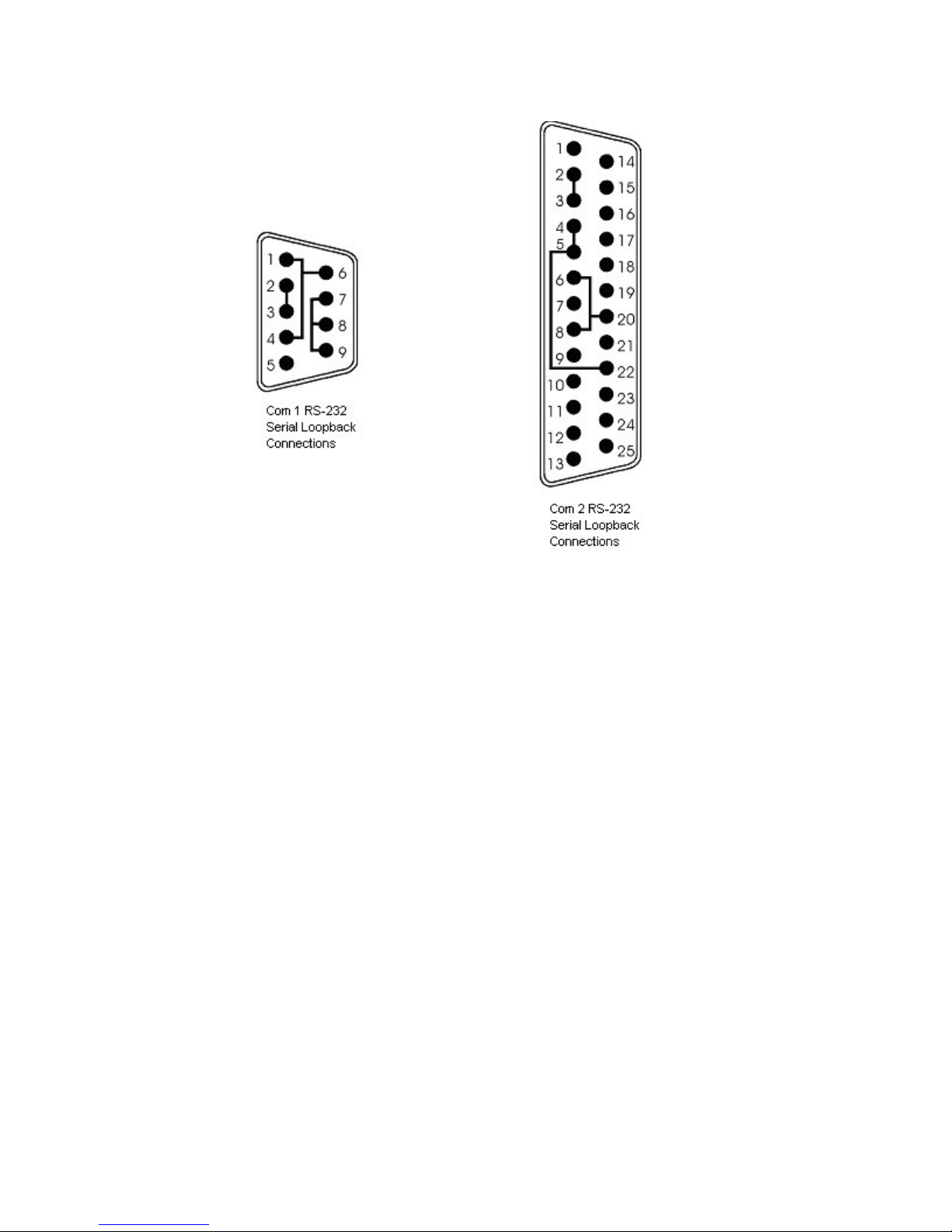
3115T R3 Thin Line Industrial Flat Panel PC Chapter 5 – Troubleshooting
Figure 5–1. Serial Loopback Connections
62 141876(E)
Page 67
3115T R3 Thin Line Industrial Flat Panel PC Chapter 5 – Troubleshooting
Running the Tests
To run the test, insert the diagnostics disk into drive A. Turn on the computer (the
diagnostics program will boot-up). Figure 5–2 shows the Main Menu.
Copyright 2002, Xycom, Inc. All rights reserved.
Diagnostic Tests Sequence/Selection Menu (Rel. xx)
1. WILL pause on error
2. SINGLE PASS test mode
3. Save setup to file
4. Extract setup from a file
5. Auto-select tests
6. Deselect all tests
7. Quit and exit to DOS
8. Return to previous screen
A) RAM Test
B) Video RAM Test
C) Extended RAM Test
D) Real Time Clock Test
E) COM1 Serial Port Test
F) COM2 Serial Port Test
G) COM3 Serial Port Test
H) COM4 Serial Port Test
I) Math Coprocessor Test
J) Video Adjustments Test
[ENTER]=START TESTING
Use the letters to move the cursor and select/deselect, or use the arrow
keys to move, then use the [SPACE] key to select/deselect a test or
function.
Figure 5–2. Main Menu
K) Video Interface Test
L) Speaker Port Test
M) LPT1: Printer Port Test
N) LPT2: Printer Port Test
O) C: Hard Drive Interface Test
P) D: Hard Drive Interface Test
Q) A: Floppy Drive Interface Test
R) B: Floppy Drive Interface Test
S) Keyboard, Keypad Tests
≡ = Test Selected
Note
Please read the DIAG.TXT file on the diagnostics disk for detailed information
about the tests.
Avoid repeated running of any hard disk diagnostic utility if you use the Solid
State (Flash) drive option. The Flash drive has a limited number of writes to
each logical sector. Repeated writes from a diagnostic utility will prematurely
shorten the life of the drive.
Note
63 141876(E)
Page 68

3115T R3 Thin Line Industrial Flat Panel PC Chapter 5 – Troubleshooting
Reinstalling Operating Systems
The 3115T R3 CPU ships with MS-DOS preinstalled. Optionally available, are
Windows 98, Windows 2000, Windows NT, and Windows XP Professional
operating systems. If you want to install a different operating system, refer to that
operating system’s manual for directions.
Note
If you need to reinstall the Windows 98, Windows 2000, Windows NT, or
Windows XP Professional operating system, you must have an internal CDROM drive or an external parallel port CD-ROM drive. Windows NT and
Windows XP ship only on CD-ROM.
MS-DOS Reinstallation
If you need to reinstall MS-DOS, refer to the Xycom Automation Workstation
Recovery Media Software Installation Instructions for Microsoft DOS 6.22 (shipped
with systems preinstalled with MS-DOS). This document is devoted to the
reinstallation of your MS-DOS operating system and drivers utilizing the Recovery
Media provided with your Xycom Automation industrial computer.
Note
This procedure assumes that the computer hard disk drive has
been completely corrupted or replaced.
Warning
This procedure will destroy data that may exist on the hard disk
drive.
Windows 98 Reinstallation
If you need to reinstall the Windows 98 operating system, refer to the Xycom
Automation Workstation Recovery Media Software Installation Instructions for
Microsoft Windows 98 (shipped with systems preinstalled with Windows 98). This
document is devoted to the reinstallation of your Microsoft Windows 98 operating
system and drivers utilizing the Recovery Media provided with your Xycom
Automation industrial computer.
Note
This procedure assumes that the computer hard disk drive has
been completely corrupted or replaced.
64 141876(E)
Page 69

3115T R3 Thin Line Industrial Flat Panel PC Chapter 5 – Troubleshooting
Warning
This procedure will destroy data that may exist on the hard disk
drive.
Windows 2000 Reinstallation
If you need to reinstall the Windows 2000 operating system, refer to the Xycom
Recovery for Xycom Automation Windows 2000 Workstation (shipped with systems
preinstalled with Windows 2000). This document is devoted to the reinstallation of
your Windows 2000 operating system and drivers utilizing the Recovery Media
provided with your Xycom Automation industrial computer.
Note
This procedure assumes that the computer hard disk drive has
been completely corrupted or replaced.
Warning
This procedure will destroy data that may exist on the hard disk
drive.
Windows NT Reinstallation
If you need to reinstall the Windows NT operating system, refer to the Xycom
Recovery for Xycom Automation Windows NT Workstation (shipped with systems
preinstalled with Windows NT). This document is devoted to the reinstallation of
your Windows NT Workstation 4.0 operating system and drivers utilizing the
Recovery Media provided with your Xycom Automation industrial computer.
Note
This procedure assumes that the computer hard disk drive has
been completely corrupted or replaced.
Warning
This procedure will destroy data that may exist on the hard disk
drive.
65 141876(E)
Page 70
3115T R3 Thin Line Industrial Flat Panel PC Chapter 5 – Troubleshooting
Windows XP® Reinstallation
If you need to reinstall the Windows XP Professional operating system, refer to the
Windows XP Professional CD-ROM (shipped with systems preinstalled with
Windows XP Professional).
Note
This procedure assumes that the computer hard disk drive has
been completely corrupted or replaced.
Warning
This procedure will destroy data that may exist on the hard disk
drive.
If you want to install a new operating system or reinstall a current operating
system, refer to the operating system’s manual for directions.
Installing Drivers
This section describes how to install the drivers associated with the system.
For further assistance, contact Xycom Automation technical
support at 734-944-0482 or [email protected].
Video Drivers
Video drivers and the expansion utilities are on the Documentation and Support
Library CD included with the documentation kit.
Choose the video driver for your operating system from the following directory on
the Documentation and Support Library CD:
\DRIVERS\VIDEO\POS370N\SIS\630
Video Expansion
This section deals with the hardware expansion capability of the video controller
chip in DOS applications.
Note
66 141876(E)
Page 71

3115T R3 Thin Line Industrial Flat Panel PC Chapter 5 – Troubleshooting
Note
It is not necessary to read this section if you are a Windows or
OS/2® user and do not plan to run DOS applications.
Unlike a CRT monitor, a flat panel display has a fixed horizontal and vertical
resolution. There are many DOS video modes whose resolution is less than that of a
flat panel display. In order to more efficiently make use of the flat panel display’s
active area, it is necessary to employ an expansion technique, which stretches the
lower resolution information to fill the higher resolution of the display.
For example, DOS defaults to VGA video mode 3+. This is an 80 column, 25-row
text only screen whose effective resolution is 640 dots x 400 scan lines. Because of
this, the 800 x 600 display of the system will be partially filled by the 640 x 400
resolution of this particular mode. The expansion function uses lower resolutions
that will better utilize the display by stretching the information in an attempt to fill
the display.
Operating systems such as Microsoft Windows 98 and Windows NT use display
drivers to handle the different flat panel displays. Here, expansion is not necessary
since there is a specific driver for each resolution display.
Expansion does not add any resolution to the existing information; it simply stretches
the information to better fit the display. Text and graphic screens can look somewhat
grainy from the process of expansion.
Touch Screen Drivers
If you have a touch screen driver that has been factory installed, you will also
receive, pre-loaded and at no extra charge: MS-DOS, Windows 98, Windows 2000,
Windows NT, and Windows XP Professional touch screen drivers.
If you ordered a system pre-loaded with an operating system, the
touch screen driver was pre-installed.
You must install the corresponding touch screen driver software if you change the
operating system. The touch screen drivers are located on the Document and
Support Library CD under:
\DRIVERS\TOUCHSREEN\TOUCHKIT
Note
67 141876(E)
Page 72
3115T R3 Thin Line Industrial Flat Panel PC Chapter 5 – Troubleshooting
Miscellaneous Drivers
Refer to your operating system and peripheral manuals for information on installing
drivers related to these items.
Note
If you ordered a system with Windows pre-loaded, you may have to purchase
and install an external parallel port CD-ROM drive, or order your system with
a CD-ROM drive pre-installed, to be able to install Windows drivers. The
Windows operating system ships only on CD-ROM.
68 141876(E)
Page 73
Appendix A – Watchdog Timer
The Watchdog Timer is a device to ensure that standalone systems can always
recover from abnormal conditions that cause the system to crash. These conditions
may result from an external EMI or a software bug. When the system stops working,
hardware on the board will perform hardware reset (cold boot) to bring the system
back to a known state.
Three I/O ports control the operation of Watch-Dog Timer.
440 (hex) Write
440 (hex) Write Disable the Watchdog Timer.
Set Watchdog Time period
Enable the refresh the Watchdog Timer.
Prior to enable the Watch-Dog Timer, user has to set the time-out period. The
resolution of the timer is 1 minute and the range of the timer is from 1 min to 255
min. You need to send the time-out value to the I/O port – 440H, and then enable it
by write data from the same I/O port – 440H(value is 01h-ffh). This activates the
timer that will eventually time out and reset the CPU board. To ensure that this reset
condition won’t occur, the Watch-Dog Timer must be periodically refreshed by write
the same I/O port 440H(the same value is 01h-ffh). This must be done within the
time-out period. (Refer to the example program.) Finally, we have to disable the
Watchdog timer by write the I/O port -- 440H (value is 0h). Otherwise, the system
could reset unconditionally.
Watchdog Timer Type Setting By RESET
Write port 440: WDT Enable & Time-out Period
PERIOD Value
1 – 255 min. 01 – FF
Write port 440: WDT Disable
Function Value
Disable 00
69 141876(E)
Page 74

3115T R3 Thin Line Industrial Flat Panel PC Appendix A – Watchdog Timer
Example assembly program:
WDT_PORT = 440H
;;INITIAL TIMER COUNTER
MOV DX, WDT_PORT
MOV AL, 1 ;;1 minute
OUT DX, AL ;;start counter
W_LOOP:
MOV DX, WDT_PORT
MOV AL, 0
OUT DX, AL ;;stop counter
MOV DX, WDT_PORT
MOV AL, 1
OUT DX, AL ;;restart counter
;;ADD YOUR APPLICATION HERE
CMP EXIT_AP, 0
JNE W_LOOP
MOV DX, WDT_PORT
MOV AL, 0
OUT DX, AL
;;EXIT AP
70 141876(E)
Page 75

Appendix B – Power On Self Test Messages
POST Messages
During the Power On Self Test (POST) if the BIOS detects an error, it will either
sound a beep code or display a message.
If a message is displayed, it will be accompanied by:
PRESS F1 TO CONTINUE, CTRL-ALT-ESC OR DEL TO ENTER SETUP
POST Beep
There are two kinds of beep codes in BIOS:
Single long beep followed by three short beeps—This code indicates that a video
error has occurred and the BIOS cannot initialize the video screen to display any
additional information.
Repeating long beep—This code indicates that a DRAM error has occurred.
Error Messages
One or more of the following messages may be displayed if the BIOS detects an
error during the POST. This list includes messages for both the ISA and the EISA
BIOS.
Table B–1. Error Messages
Error Messages Cause/Solution
CMOS BATTERY HAS FAILED
CMOS CHECKSUM ERROR
DISK BOOT FAILURE, INSERT SYSTEM DISK
AND PRESS ENTER
DISKETTE DRIVES OR TYPES MISMATCH
ERROR - RUN SETUP
DISPLAY SWITCH IS SET INCORRECTLY
DISPLAY TYPE HAS CHANGED SINCE LAST
BOOT
CMOS battery is no longer functional. It should be replaced.
Checksum of CMOS is incorrect. A weak battery may have caused
this error; replace if necessary. It may also indicate that CMOS has
become corrupt.
No boot device was found. This could mean that either a boot drive
was not detected or the drive does not contain proper system boot
files. Insert a system disk (formatted as a boot device) into Drive A:
and press Enter. If you assumed the system would boot from the
hard drive, make sure the controller is inserted correctly and all
cables are properly attached, then reboot the system.
Type of diskette drive installed in the system is different from the
CMOS definition. Run Setup to reconfigure the drive type correctly.
The display switch on the motherboard is set to a different setting
than indicated in Setup. Determine which setting is correct and then
either turn off the system and change the jumper, or enter Setup and
change the VIDEO selection.
Since the last powering off the system, the display adapter has been
changed. You must configure the system for the new display type.
71 141876(E)
Page 76

3115T R3 Thin Line Industrial Flat Panel PC Appendix B – Power On Self Test Messages
Error Messages Cause/Solution
EISA CONFIGURATION CHECKSUM ERROR
PLEASE RUN EISA CONFIGURATION UTILITY
EISA CONFIGURATION IS NOT COMPLETE
PLEASE RUN EISA CONFIGURATION UTILITY
ERROR ENCOUNTERED INITIALIZING HARD
DRIVE
ERROR INITIALIZING HARD DISK
CONTROLLER
FLOPPY DISK CNTRLR ERROR OR NO CNTRLR
PRESENT
INVALID EISA CONFIGURATION
PLEASE RUN EISA CONFIGURATION UTILITY
KEYBOARD ERROR OR NO KEYBOARD
PRESENT
KEYBOARD IS LOCKED OUT - UNLOCK THE
KEY
MEMORY ADDRESS ERROR AT ... Indicates a memory address error at a specific location. You can use this
MEMORY PARITY ERROR AT ... Indicates a memory parity error at a specific location. You can use this
MEMORY SIZE HAS CHANGED SINCE LAST
BOOT
MEMORY VERIFY ERROR AT ... Indicates an error verifying a value already written to memory. Use the
OFFENDING ADDRESS NOT FOUND This message is used in conjunction with the I/O CHANNEL CHECK and
OFFENDING SEGMENT This message is used in conjunction with the I/O CHANNEL CHECK and
PRESS A KEY TO REBOOT This will be displayed at the bottom screen when an error occurs that
PRESS F1 TO DISABLE NMI, F2 TO REBOOT When BIOS detects a Non-maskable Interrupt condition during boot, this will
RAM PARITY ERROR - CHECKING FOR
SEGMENT
SHOULD BE EMPTY BUT EISA BOARD FOUND
PLEASE RUN EISA CONFIGURATION UTILITY
SHOULD HAVE EISA BOARD BUT NOT FOUND
PLEASE RUN EISA CONFIGURATION UTILITY
The EISA non-volatile RAM checksum is incorrect or cannot correctly read
the EISA slot. This can indicate either the EISA non-volatile memory has
become corrupt or the slot has been configured incorrectly. Verify the card is
installed firmly in the slot. When this error appears, the system will boot in
ISA mode allowing you to run the EISA Configuration Utility.
The slot configuration information stored in the EISA non-volatile memory is
incomplete. When this error appears, the system will boot in ISA mode
allowing you to run the EISA Configuration Utility.
Check that the adapter is installed correctly and all cables are firmly
attached. Verify that the correct hard drive type is selected in Setup.
See the cord is correctly and firmly installed in the bus. Verify the correct
hard drive type is selected in Setup. Check jumper settings on the hard drive.
Make sure the controller is installed correctly and firmly. If there are no floppy
drives installed, be sure the Diskette Drive selection in Setup is set to NONE.
The non-volatile memory containing EISA configuration information was
programmed incorrectly or has become corrupt. The system will boot in ISA
mode allowing you to run the EISA Configuration Utility and correctly
program the memory.
Make sure the keyboard is attached correctly and no keys are being pressed
during the boot. If you are purposely configuring the system without a
keyboard, set the error halt condition in Setup to HALT ON ALL, BUT
KEYBOARD. This will cause the BIOS to ignore the missing keyboard and
continue the boot.
BIOS detected the keyboard is locked. P17 of keyboard controller is pulled
low.
location along with the memory map for your system to find and replace the
bad memory chips.
location along with the memory map for your system to find and replace the
bad memory chips.
Memory has been added or removed since the last boot. In EISA mode use
Configuration Utility to reconfigure the memory configuration. In ISA mode
enter Setup and enter the new memory size in the memory fields.
location along with your system's memory map to locate the bad chip.
RAM PARITY ERROR messages when the segment that has caused the
problem cannot be isolated.
RAM PARITY ERROR messages when the segment that has caused the
problem has been isolated.
requires you to reboot. Press any key to reboot.
allow you to disable the NMI and continue to boot, or you can reboot the
system with the NMI enabled.
Indicates a parity error in Random Access Memory.
A valid board ID was found in a slot that was configured as having
no board ID. When this error appears, the system will boot in ISA
mode allowing you to run the EISA Configuration Utility.
The board installed is not responding to the ID request, or no board
ID has been found in the indicated slot. When this error appears, the
system will boot in ISA mode allowing you to run the EISA
Configuration Utility.
72 141876(E)
Page 77

3115T R3 Thin Line Industrial Flat Panel PC Appendix B – Power On Self Test Messages
Error Messages Cause/Solution
SLOT NOT EMPTY
SYSTEM HALTED, (CTRL-ALT-DEL) TO
REBOOT ...
WRONG BOARD IN SLOT
PLEASE RUN EISA CONFIGURATION UTILITY
FLOPPY DISK(S) FAIL (80)
FLOPPY DISK(S) FAIL (40)
HARD DISK(S) FAIL (80)
HARD DISK(S) FAIL (40)
HARD DISK(S) FAIL (20)
HARD DISK(S) FAIL (10)
HARD DISK(S) FAIL (08)
MANUFACTURING POST LOOP.
BIOS ROM CHECKSUM ERROR - SYSTEM
HALTED.
MEMORY TEST FAIL.
A slot designated as empty by the EISA Configuration Utility actually
contains a board. When this error appears, the system will boot in
ISA mode allowing you to run the EISA Configuration Utility.
The present boot attempt has been aborted and the system must be
rebooted. Press and hold down the CTRL and ALT keys and press
DEL.
The board ID does not match the ID stored in the EISA non-volatile
memory. When this error appears, the system will boot in ISA
mode, allowing you to run the EISA Configuration Utility.
Unable to reset floppy subsystem
Floppy type dismatch
HDD reset failed
HDD controller diagnostics failed
HDD initialization error
Unable to recalibrate fixed disk
Sector Verify failed
System will repeat POST procedure infinitely while the P15 of
keyboard controller is pulled low. This is also used for M/B burn in
test.
The checksum of ROM address F0000H-FFFFFH is bad.
BIOS reports the memory test failed if the onboard memory is tested
error.
73 141876(E)
Page 78
Appendix C – DMA, IRQ and 1st MB Memory
DMA Channel Assignments
Table C–1. DMA Channel Assignments
Channel Description
0 Available
1 Available
2 Floppy Disk (8-bit transfer)
3 Available
4 Cascade for DMA controller 1
5 Sound
6 Available
7 Available
IRQ Mapping Chart
Table C–2. IRQ Mapping
IRQ0 System Timer IRQ8 RTC Clock
IRQ1 Keyboard IRQ9 USB
LAN
IRQ2 Cascade to IRQ
Controller
IRQ3 (COM2) IRQ11 (COM4)
IRQ4 (COM1) IRQ12 PS/2 Mouse
IRQ5 Sound (LPT2) IRQ13 FPU
IRQ6 FDC IRQ14 Primary IDE
IRQ7 LPT1 IRQ15 Secondary IDE
IRQ10 Touchscreen (COM3)
Note
All IRQs have been assigned to the listed devices, so if you want to add any
additional device interface, you must free the unused IRQ first. For example, if
you don’t use USB K/B or Mouse, then IRQ10 may be set free.
74 141876(E)
Page 79
3115T R3 Thin Line Industrial Flat Panel PC Appendix C – DMA, IRQ and 1st MB Memory
1st MB Memory Address Map
Table C–3. 1st MB Memory Address Map
Memory Address Description
00000-9FFFF System Board extension for ACPI BIOS
A0000-CBFFF SIS630
F0000-FFFFF System Board extension for ACPI BIOS
CC000-CFFFF Unavailable for use by device
I/O Addresses
Table C–4. I/O Addresses
I/O Address Range Description
000-01F DMA Controller #1
020-021 Interrupt Controller #1, Master
040-05F 8254 Timer
060-06F 8042 (Keyboard Controller)
070-07F Real Time Clock, NMI Mask
080-09F DMA Page Register
0A0-0BF Interrupt Controller #2
0C0-0DF DMA Controller #2
0F0 Clear Math Coprocessor Busy
0F1 Reset Math Coprocessor
0F8-0FF Math Coprocessor
408-409 Digital Input/Output
170-177
1F0-1F7
270-27F Printer Port (LPT2)
2E8-2EF Serial Port 4 (COM4)
2F8-2FF Serial Port 2 (COM2)
378-37F Parallel Printer Port 1 (LPT1)
380-38F SDLC, Bisynchronous 2
3A0-3AF Bisynchronous 1
3B0-3BB SIS 630
3C0-3DF SIS 630
3E8-3EF Serial Port 3 (COM3)
3F0-3F7 Diskette Controller
3F8-3FF Serial Port 1 (COM1)
440 Watch-dog timer
Fixed Disk
75 141876(E)
Page 80

Appendix D – How to Upgrade a New BIOS
Please contact the Xycom Automation Application Engineering Department at 734429-4971 to obtain the latest BIOS.
BIOS Update Procedure
Notes
A. This procedure will erase any prior data on that floppy, so please proceed
accordingly.
B. Typically four files will be transferred, only COMMAND.COM being visible
when running a simple directory listing.
C. Please leave the diskette un-write protected for the balance of this
procedure.
1. Make a boot disk. Go to the DOS command prompt in MS-DOS or Windows 9x
and, with an available floppy disk in "A", type "format A:/s" That will format the
floppy and transfer the needed system files to it.
2. Download the BIOS upgrade file and awdflash.exe utility from an ICP web site
to a temporary directory on your hard drive, or directly to the floppy formatted in
step 1.
3. Copy (BIOS file and awdflash.exe) files to the boot floppy disk.
4. Reboot the system to the DOS command prompt using the boot disk made in the
previous steps.
5. At the DOS command prompt, awdflash filename.xxx, (filename.xxx is the file
name of the upgraded BIOS file), press Enter.
6. The first prompted option is to save the old BIOS. It is recommended that this
option be selected in case it is later decided not to use the new version once it is
installed. To save, enter Y. To not save, enter N.
Notes
A. DO NOT save the old BIOS with the same file name as the new BIOS. If
the same file name is used, the new BIOS will write over the old BIOS with
no prompted warning.
B. If the old BIOS is not saved write down the version number of the old BIOS
and store it with your important computer documents. If not saving old
BIOS, enter N (for "no") and skip to step 9.
76 141876(E)
Page 81
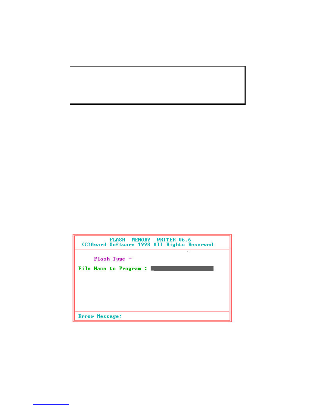
3115T R3 Thin Line Industrial Flat Panel PC Appendix D – How to Upgrade a New BIOS
7. Enter a NEW name for the old BIOS file, press Enter.
8. The second prompted option will be whether you want to flash your BIOS. Enter
Y for yes, N for no.
Warning
Once the Enter key is pressed, DO NOT touch the keyboard,
reset button, or power switch while flashing is in progress. A
progress bar on the screen will show the progress of the flashing.
9. When the flashing process is complete, you will be asked to reset or power off
the system. Remove the floppy disk from the drive and reset or power off the
system.
10. Reboot the system and note that the BIOS version on the initial boot-up screen
has changed to the new BIOS version. Your BIOS upgrade is now complete.
Recovering Your Old BIOS
1. Boot the system with the floppy disk that contains the new BIOS. If you do not
have the floppy disk, repeat steps 1, 2, and 3 of the BIOS Upgrade Procedure
above for the version of the BIOS recovering.
2. Complete steps 4 and 5 (filename.xxx is the name of the recovered BIOS file).
Select N for no in step 6, and continue with steps 8, 9, and 10.
Install screen:
77 141876(E)
Page 82

Index
Arm mounting......................................................... 14
Audio line-in connector ..........................................29
Audio panel connector ...........................................30
Audio speaker output connector ............................30
Award BIOS setup..................................................15
BIOS recovery........................................................ 77
BIOS setup............................................................. 15
advanced chipset features ................................. 43
advanced CMOS features.................................. 39
exit without save.................................................58
frequency/voltage congtrol.................................56
getting help ........................................................33
integrated peripherals ........................................47
main menu .........................................................34
overview.............................................................32
PC health status................................................. 55
PnP/PCI configuration setup..............................53
power management setup .................................50
save and exit setup ............................................ 58
standard CMOS features ...................................36
starting ...............................................................32
supervisor/user passwords ................................57
using ..................................................................33
BIOS upgrades ......................................................76
Chassis intrusion detection connector ...................30
CMOS setting......................................................... 19
COM2 setting ......................................................... 19
Connectors
audio line-in........................................................ 29
audio panel ........................................................30
audio speaker ....................................................30
chassis intrusion detection.................................30
fan......................................................................28
home networking................................................ 29
IrDA infrared interface port................................. 27
keyboard/mouse ................................................25
LAN RJ45........................................................... 28
LCD backlight..................................................... 28
parallel port ........................................................21
serial ports .........................................................22
USB port ............................................................26
VGA ...................................................................27
Cooling fan connector............................................28
CPU board .............................................................15
audio line-in connector.......................................29
audio panel connector........................................ 30
audio speaker output connector......................... 30
chassis intrusion detection connector................30
external switches and indicators ........................ 26
Fan connector .................................................... 28
home networking connector...............................29
IrDA infrared interface port connector ................27
keyboard/mouse connector................................ 25
LAN RJ45 connector ..........................................28
layout .................................................................17
LCD backlight connector....................................28
parallel port connector .......................................21
product overview................................................15
serial port connectors......................................... 22
specifications ................................................. 3, 15
USB port connector............................................ 26
VGA connector................................................... 27
CPU board settings
CMOS ................................................................19
COM port IR and voltage ...................................19
COM2................................................................. 19
CPU ...................................................................18
flash disk ............................................................ 18
78 141876(E)
Page 83

Index
IR power............................................................. 20
LCD panel power ...............................................19
USB port power.................................................. 21
Dimensions
mechanical...........................................................5
Disk drive bay ..........................................................1
Display backlight connector ...................................28
DMA channel assignments ....................................74
DMA, IRQ and memory map.................................. 74
Drivers
installing ............................................................. 66
miscellaneous ....................................................68
touch screen ......................................................67
video ..................................................................66
Environmental specifications ...................................4
Error messages (power on self test .......................71
External indicators
CPU board .........................................................26
External switches and indicators
CPU board .........................................................26
Fan connector ........................................................ 28
Flash disk
setting ................................................................18
Fuse
replacement .......................................................59
General information .................................................1
Hard disk drive
installation/removal ..............................................9
Home networking connector ..................................29
I/O address map ....................................................75
Indicators
CPU board .........................................................26
Infrared interface port
connector ...........................................................27
power setting...................................................... 20
Input/output address map ......................................75
Installation
driver .................................................................. 66
hard disk drive...................................................... 9
operating systems ..............................................64
IR port
power setting...................................................... 20
setting ................................................................19
IrDA infrared interface port
connector ...........................................................27
IRQ map................................................................. 74
Keyboard/mouse
connector ...........................................................25
LAN RJ45
connector ...........................................................28
LCD display
backlight connector............................................28
specifications .......................................................2
LCD panel
power setting...................................................... 19
Local area network connector................................28
Maintenance ..........................................................59
general ............................................................... 59
hard drive ........................................................... 59
Mechanical diminsions.............................................5
Memory address (1st MB) map............................... 75
Memory map .......................................................... 74
Mounting
arm.....................................................................14
panel ..................................................................11
wall.....................................................................12
Mouse
connector ...........................................................25
Operating systems
installation .......................................................... 64
Panel mounting ...................................................... 11
Parallel port
connector ...........................................................21
POST messages....................................................71
Power on self test ..................................................71
error messages .................................................. 71
POST beep ........................................................71
POST messages................................................71
Power supply
specifications .......................................................2
79 141876(E)
Page 84

Index
Preventive maintenance ........................................59
general ............................................................... 59
hard drive ........................................................... 59
Product information
CPU board .....................................................3, 15
disk drive bay ....................................................... 1
environmental specifications................................ 4
general ................................................................. 1
LCD display.......................................................... 2
mechanical dimensions........................................ 5
power supply........................................................2
system setup........................................................6
touch screen ........................................................2
Product specifications
CPU board ...........................................................3
disk drive bay ....................................................... 1
environmental ......................................................4
LCD display.......................................................... 2
power supply........................................................2
touch screen ........................................................2
Recovering the old BIOS .......................................77
Removal
hard disk drive...................................................... 9
Repairs and service................................................... 60
Reverse side of unit
system setup....................................................6, 7
Serial ports
connectors .........................................................22
setting
COM port IR and voltage ...............................19
COM2............................................................. 19
Service and repairs ................................................ 60
Side view of unit
system setup........................................................8
Speaker output connector......................................30
Specifications
CPU board .....................................................3, 15
disk drive bay ....................................................... 1
environmental ......................................................4
LCD display.......................................................... 2
power supply........................................................2
touch screen ........................................................2
Switches
CPU board .........................................................26
System setup ...........................................................6
arm mounting ..................................................... 14
hard disk drive installation/removal...................... 9
panel mounting ..................................................11
reverse side of unit........................................... 6, 7
side view of unit ...................................................8
wall mounting ..................................................... 12
Touch screen
specifications .......................................................2
Touch screen drivers .............................................67
Unit reverse side ..................................................6, 7
Unit side view...........................................................8
Universal serial bus port
connector ...........................................................26
power selection .................................................. 21
Upgrading the BIOS...............................................76
USB port
connector ...........................................................26
power setting...................................................... 21
VGA connector....................................................... 27
Video drivers .......................................................... 66
Video expansion ....................................................66
Wall mounting ........................................................12
Watchdog timer......................................................69
80 141876(E)
Page 85

141876(E)
http://www.xycom.com
Xycom Automation, Inc.
734-429-4971
Fax: 734-429-1010
Canada Sales: 905-607-3400
Northern Europe Sales: +44-1604-790-767
Southern Europe Sales: +39-011-770-53-11
 Loading...