

Page 1
China Patent Numbers ZL 2016 3 0165464.8
2nd floor, Building 12, Xicheng Industrial Area, Xixiang Town,
Baoan District, Shenzhen Guangdong China. 518101
E-mail: [email protected]
Page 2

U4 SET MANUAL
WIRELESS
INEAR MONITOR SYSTEM
Page 3
CAUTION
RISK OF ELECTRIC SHOCK
DO NOT OPEN
WARNING : TO REDUCE THE RISK OF FIRE OR ELECTRIC
SHOCK: DO NOT REMOVE SCREWS.
NO USER-SERVICEABLE PARTSINSIDE.
REFER SERVICING TO QUALIFIED SERVICE PERSONNEL.
WARNING : TO REDUCE THE RISK OF FIRE OR ELECTRIC
SHOCK, DO NOT EXPOSE THE APPLIANCE TO RAIN OR
MOISTURE.
CERTIFICATION
Radio Approvals: FCC Part 15.249, FCC Part 15 B, RSS-210
(Canada), EN 300 440 (Europe), EN 301.489 (Europe), MIC
Notice No.88 Appendix No.43(Japan)
01
This Class B digital apparatus complies with Canadian
ICES-003.
IC Caution: RSS-Gen Issue 4 December 2014"&"CNR-Gen
4e Décembre 2014:
This device complies with Industry Canada licence-exempt RSS standard(s). Operation is subject to the
following two conditions: (1) This device may not cause
interference, and (2) This device must accept any
interference, including interference that may cause
undesired operation of the device.
Le présentappareilestconforme aux CNR d'Industrie
Canada applicables aux appareils radio exempts de
licence. L'exploitationestautorisée aux deux conditions
suivantes: (1) l'appareil ne doit pas produire de brouillage,
et (2) l'utilisateur de l'appareildoit accepter tout brouillageradioélectriquesubi, mêmesi le brouillageest susceptible
d'encompromettre le fonctionnement.
Page 4

FCC CERTIFICATION
THIS DEVICE COMPLIES WITH PART 15 OF THE FCC RULES.
OPERATION IS SUBJECT TO THE FOLLOWING TWO
CONDITIONS: (1) THIS DEVICE MAY NOT CAUSE HARMFUL
INTERFERENCE, AND (2) THIS DEVICE MUST ACCEPT ANY
INTERFERENCE RECEIVED, INCLUDING INTERFERENCE
THAT MAY CAUSE UNDESIRED OPERATION.
WARNING:
Changes or modifications not expressly approved in
writing by Xvive may void the users authority to operate
this equipment.
RF EXPOSURE STATEMENT:
This transmitter must not be co-located or operated in
conjunction with any other antenna or transmitter.
NOTE:
This equipment has been tested and found to comply with
the limits for a Class B digital device, pursuant to part 15 of
the FCC Rules. These limits are designed to provide
reasonable protection against harmful interference in a
residential installation. This equipment generates, uses
and can radiate radio frequency energy and, if not
installed and used in accordance with the instructions,
may cause harmful interference to radio communications.
There is no guarantee that interference will not occur in a
particular installation. If this equipment does cause
harmful interference to radio or television reception,
which can be determined by turning the equipment off
and on, the user is encouraged to try to correct the
interference by one or more of the following
MEASURES:
- Reorient or relocate the receiving antenna.
- Increase the separation between the equipment and
receiver.
- Connect the equipment into an outlet on a circuit
different from that to which the receiver is connected.
- Consult the dealer or an experienced radio/TV
technician for help.
02
Page 5
PLEASE READ THESE INSTRUCTIONS IN A SAFE PLACE
IMPORTANT SAFETY INSTRUCTIONS
WARNING: BEFORE USING YOUR XVIVE U4 MICROPHONE WIRELESS SYSTEM,
CAREFULLY READ THE OPERATING INSTRUCTIONS.
1. Observe all instructions carefully in the U3C set manual.
2. Do not to perform service operations beyond those
described in the U4 set manual. Services required when
the apparatus has been damaged in any way, such as:
• Liquid has been spilled or objects have fallen into the
apparatus
• The unit has been exposed to rain or moisture
• The unit does not operate normally or changes in
performance in a significant way
• The unit is dropped or the enclosure is damaged
03
3. Do not place near heat sources, such as radiators, heat
registers, or appliances which produce heat.
4. Guard against objects or liquids entering the device.
Do not use or place unit near water.
5. Clean only with a dry cloth.
6. Only use attachments/accessories specified by the
manufacturer.
7. Prolonged listening at high volume levels may cause
irreparable hearing loss and/or damage. Always be sure
to practice “safe listening.”
Page 6
WARNING
U4 SET PRODUCT INTRODUCTION
LISTENING TO AUDIO AT EXCESSIVE VOLUMES CAN
CAUSE PERMANENT HEARING DAMAGE. USE AS LOW
A VOLUME AS POSSIBLE.
Over exposure to excessive sound levels can damage
your ears resulting in permanent noise-induced
hearing loss. Do not use earphones for a long time
and set the volume below 70% or lower.
PACKAGE DETAILS
U4 Transmitter
U4 Receiver
USB Cable
XLR Male to 1/4" TS Male Adapter
Manual
Bag
1PCS
1PCS
1PCS
1PCS
1PCS
1PCS
U4-person wireless monitoring system provides better
sound feedback for stage performers and performance
quality. As a portable wireless system, you don't need to
set up. Just plug-and-play to quickly build your monitoring system.
FEATURES:
• 2.4Ghz wireless In-ear monitor system
• Create your personal or team's monitor system
• Send audio wirelessly to performers onstage
• 90 foot range
• Support XLR or TRS input
• Up to 107 dB signal-to-noise ratio provides clear,
detailed audio at any volume
• Plug and Play, focus on the performance
• All-metal Receiver
• Slim, lightweight bodypack attaches easily to a belt or
guitar strap
04
Page 7
2
3
4 5
6
10
05
BASIC OPERATION
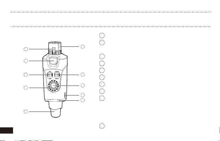
U4 TRANSMITTER
1 Input: XLR balanced input jack
1
7
8
9
2 Spring: Circumferential ground spring providing an
accurate connection to the mating shell
3 Lock: secures transmitter
4 Aux/Line mode: Connect to Aux or other line out
5 Power switch: switches unit on/off
6 Channel status LED: indicates selected channel
7 Channel switch: selects Channels 1-6
8 USB charging port
9 Power status LED: indicates power status:
Led off = 100% ~ 30%
Solid red = 29% ~ 11%
Flickering red = less than 10%
10 Antenna.
Page 8
BASIC OPERATION
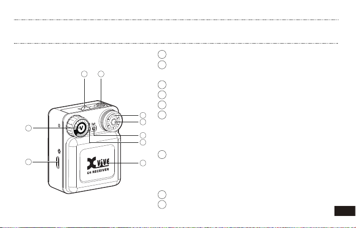
U4 RECEIVER
1 Power switch: switches unit on/off
21
5
8
2 Headphone Output: 3.5mm output
Connect to earphones or headphones
3 Channel status LED: indicates selected channel
4 Channel switch: selects Channels 1-6
5 Volume control:Adjust the volume of headphone output
3
6 RF Status LED:
4
6
7
9
ON = Transmitter is on and link is established
Flashing = Signal connection interference
OFF = Transmitter off or unlinked
7 Power status LED: indicates power status:
Led off = 100% ~ 30%
Solid red = 29% ~ 11%
Flickering red = less than 10%
8 USB charging port
9 Antenna.
06
Page 9
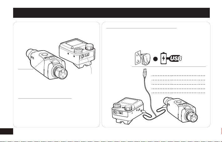
POWER ON
POWER ON
Start the power switch,
the channel indicator
will light up.
07
ON
OFF
POWER ON
QUICK START
BATTERIES AND CHARGING
U4 provides USB charging cable,you can connect to USB
Charger Adapter or other USB charging devices
Note: Turn off the power switch while charging. Please do
not use U4 when charging, which may reduce battery life.
Connect to
the socket
* Always store U4 at
room temperature
* When storing the unit,
please check the
battery state regularly
and charge if necessary.
OR
CHARGING TIMES BATTERY LIFE
0:15
0:30
1:00
2:30
Connect
Power
30 min
1 hours
2 hours
5 hours
Page 10

CHANNEL SWITCH
CHANNEL SWITCH
SINGLE TRANSMITTER AND
MULTIPLE RECEIVERS
If you want to add more receiver,
just set the receivers to the same
channel as the transmitter.
1
2
6
PAIR TRANSMITTER AND RECEIVER
3
5
4
U4 has six channels.
Use the channel switch button to switch
the channel. Set the Receiver channel
same with Transmitter. The blue Led
signal on the receiver will always be on
when the connection is successful.
MAX. 6 CHANNELS
08
Page 11
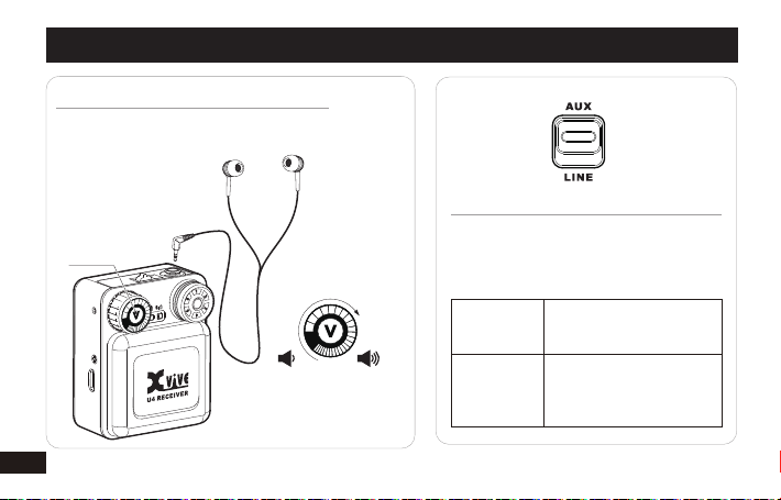
VOLUME ADJUSTING
LISTENING TO AUDIO AT EXCESSIVE VOLUMES CAN CAUSE
PERMANENT HEARING DAMAGE. USE AS LOW A VOLUME
AS POSSIBLE.
VOLUME
SWITCH
Please do not adjust
the volume to more
than 70%.
09
QUICK START
<70%
ADJUST TRANSMITTER LEVELS
Adjusting Gain and Listening Volume
For the best audio quality, start by adjusting
the levels from the mixer or audio source and
maximizes the signal-to-noise ratio.
Line (+4 dBu)
Aux (-10 dBV)
Use with mixers or other
professional audio devices
that send line-level signals.
Use when connecting
consumer audio devices
such as portable audio
players or computers.
Page 12
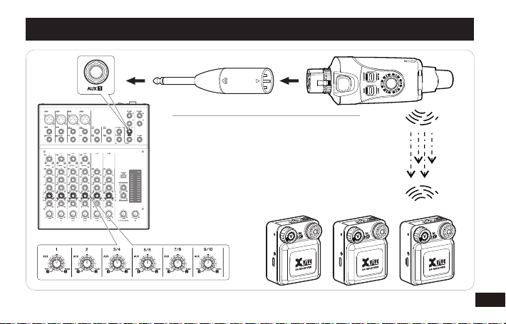
OPERATION
CREATING MONITOR WITH AUX
1. Transmitter connect Mixer Aux send
2. Trun on the Receiver, adjust the volume of the
Receiver, and gradually increase from small to
large to reach the appropriate volume state
3. Adjust mixer each Aux channel output levels,
mixer and send the signal to Transmitter。
Note: The channel faders on most mixers do not
affect the volume of the Aux sends.
10
Page 13
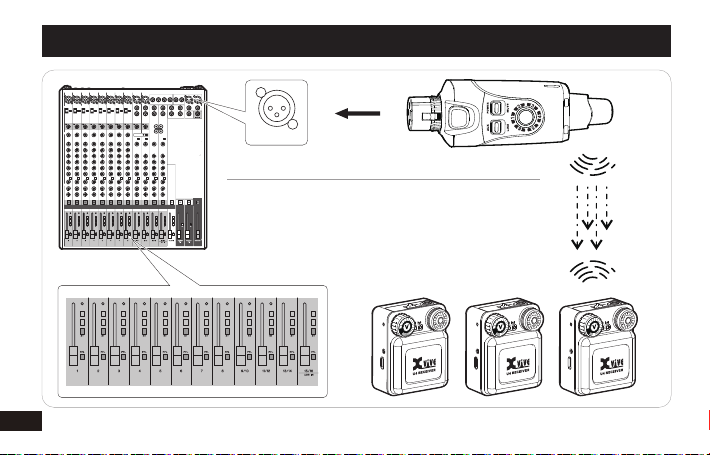
OPERATION
MIAN OUTPUT
CREATING MONITOR WITH XLR
1. Transmitter connect Mixer output or other XLR output
2. Trun on the Receiver, adjust the volume of the Receiver,
and gradually increase from small to large to reach the
appropriate volume state
3 Adjust mixer each channel faders output levels,mixer
and send the signal to Transmitter。
11
Page 14
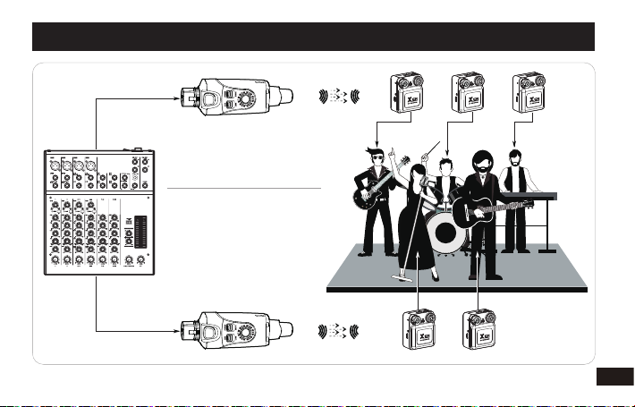
CHANNEL 1
CHANNEL 2
OPERATION
SINGLE TRANSMITTER AND
MULTIPLE RECEIVERS
When performers have different
monitoring needs, they can set
up multiple transmitters. If the
receiver is set to the channel
corresponding to the transmitter, the audio can be received.
Or creat mute rehearsal system.
12
Page 15

2.4 GHz SPECTRUM OVERVIEW AND INTERFERENCE
U4 operates within the 2.4GHz ISM band which is utilized
by Wi-Fi, Bluetooth, and other wireless devices. 2.4GHz is
an open band and, as such, does not require a license to
be used worldwide.
Tips and Methods to Improve Wireless System Performance
1) Keep more than 3 meteres distance between Receiver
unit and other WiFi transmitters such as routers.
2) Change channels to avoid interference with other WiFi
products.
3) In case of environmental interference from other WiFi
systems, shorten the distance between the receiver
and transmitter units.
13
2.4Ghz Frequency Tables
CHANNEL 1
CHANNEL 2
CHANNEL 3
CHANNEL 4
CHANNEL 5
CHANNEL 6
* U2 1~4 channels are the same as U3/U3C/U4 1~4 channels,
U2, U3/U3C and U4 use in sametime max is 6 sets.
2402MHz, 2480MHz, 2482MHz
2408MHz, 2472MHz, 2474MHz
2416MHz, 2464MHz, 2466MHz
2434MHz, 2440MHz, 2442MHz
2427MHz, 2448MHz, 2450MHz
2422MHz, 2456MHz, 2458MHz
Page 16

TROUBLESHOOTING
ISSUE SOLUTION
No Sound
Distorted Audio
Low audio output at the receiver
Signal instability: RF LED flickering
Unable to switch the channel
Multiple connect
• Check that the U4 Receiver's RF LED is lit.
• Check whether the device has a signal sent to the transmitter
• Check that the power switch is turned on for both the Transmitter and
the Receiver.
• Ensure that the U4 Transmitter and Receiver are on the same channel.
• The Receiver can be paired with one Transmitter at a time
• Check the Line/Aux setting at the transmitter and verify that the meter is not
reaching the overload
• Check Levels going in and out of the mixer. Verify that no distortion occurs in
each audio signal.
• Check receiver headphone output Volume level
• Check Transmitter mode Line/Aux.
• Check Check whether the device has enough signals level to the transmitter.
• See, “Tips and methods to improve wireless system performance page 13
• The channel switch locks after 15 seconds. Double-click the channel button
to unlock and reset.
• Use one transmitter can connect with more than 2 receivers.
14
Page 17

U4 WIRELESS INEAR MONITOR SYSTEM
Tuning Bandwidth
Working Range
Audio Frequency Response
Dynamic Range
Battery Life
RF Sensitivity
Total Harmonic distortion
RF Output Power
Operating Temperature Range
Channel Count
15
SPECIFICATIONS
2400 – 2483.5MHz
Up to 90ft Actual Range Depends On Rf Signal Absorption, Reflection
And Interference.
20Hz – 20KHz(-3dB).
107dB
5 Hours of battery life
-88dBm
0.2%
10 mW E.I.R.P. max
-18℃ to 57℃. Battery Characteristics May Limit This Range.
Up To 6 Channels
Page 18

Dimensions
Weight
Housing
Battery
Impedance
Audio input Connector
Audio output Connector
Mode
Battery life
Antennal Impedance
ANTENNA Type
Number Of Antenna
U4 TRANSMITTER U4 RECEIVER
31 X 29 X 98 mm
Molded plastic and cast metal
3.7V Rechargeable Li-ion, 860mA
Input 47kΩ(1KHz)
Molded plastic and cast metal
3.7V Rechargeable Li-ion, 1200mA
6-600Ω
Balanced XLR Male input
3.5mm stereo output
Aux mode: -10dBV | Max. +12.2dBu
Line mode: +4dBu | Max. +22dBu
Up to 5 Hours
50Ω
1/4 Wave Sleeve Dipole, Non-removable
1
Up to 5 Hours
50Ω
1/4 Wave Sleeve Dipole, Non-removable
2
16
Page 19
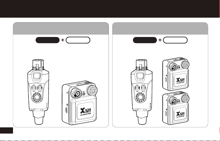
U4 SERIES
U4 SET U4R2
1 Transmitter 2 Receiver1 Transmitter 1 Receiver
U4 standard set to creat personal
Monitoring system
17
U4R2 set to creat small monitoring system
Or backup receiver
Page 20
WIRELESS INEAR MONITOR SYSTEM
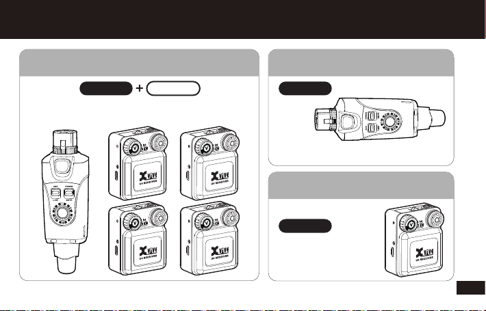
U4R4 U4T
1 Transmitter 1 Transmitter 4 Receiver
U4R4 set to creat performance monitoring system
Or mute rehearsal system
Transmitter only, you need to purchase
Additional receivers for use
1 RECEIVER
Receiver only, you need
To purchase additional
Transmitter for use
U4R
18
 Loading...