


DDiiggiittaall VViiddeeoo RReeccoorrddeerr
TTEEC
C
H
H
N
NII
C
CAALL
M
MAA
N
N
U
UAALL
2005-5 Edition
Copyright 2005 by X-Vision

2
Chapter 1
Setup Introduction
X-Vision

3
1.1 System Specification Recommendation
The below is the recommended computer specification to work with X-Vision boards.
Model XP4SW25 XP16SW50 – XP16SW100 XP16SW200- XP32SW200
CPU Pentium Celeron 1.7GHz or above Pentium IV 2.0Ghz or above
Motherboard Intel 865 Chipset Motherboard or above
(Aopen AX4SPE-N VALUE is recommended for over 200fps DVR)
OS Win 2000/XP
Memory 256 Mbyte or above 512 Mbyte
HDD 80G or above
VGA ATI Expert 2000 Pro / Geforce 2 MX200 with video ram 32M or above 64M
Power 110/220V 300W 350W
X-Vision

4
1.2 Important Notes Before Running PCDVR Server Program
Before Operating PCDVR Server Program
1) Recycle Bin Setup
Check on the box “Do not move files to the Recycle Bin. Remove files immediately when deleted.” in the prop erty of
Recycle Bin.
2) Display Setup
- Set resolution at 1024x768 and High Color 16bit.
- Set “System Standby”, “Turn off monitor” and “Turn off hard disk” at “Never” in Display Properties\Power Management
Properties\Power Schemes.
3) Rebooting Setup
We highly recommend you to set automatic daily rebooting in idle time for most stable system operation.
4) Operating System
As PCDVR Server Software was built on Windows 2000 platform, it operates most stable on Windows 2000 platform.
5) DirectX
DirectX Verison 8.1b or above
X-Vision

5
Chapter 2
DVR Hardware
X-Vision

6
2.1 DVR Line-up
Prodcut Line-up
Model Camera Display / Recording Audio D/I D/O
XP4SW25 4Ch 25fps / 25fps 1 4 4
XP16SW50 16Ch 50fps / 50fps 1 8 8
XP16SW100 16Ch 100fps / 100fps 4 8 8
XP16SW200 16Ch 200fps / 200fps 8 8 8
XP32SW200 32Ch 200fps / 200fps 8 16 16
X-Vision

7
2.2 XP4SW25
Formation : XP4SW25 board
Camera Input 1
Camera Input 2
Camera Input 4
TV Out
Camera Input 3
Watchdog Terminal
DI/DO Terminal
X-Vision

8
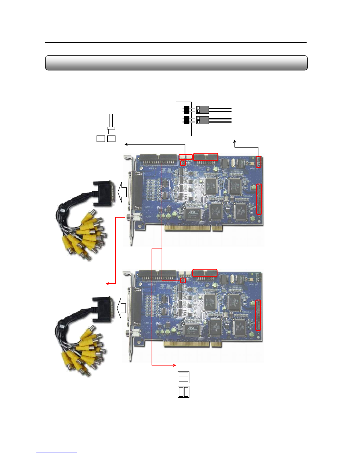
2.3 XP16SW50
Formation : XP16SW50 board + 16-Ch BNC Cable
TV Out Impedence Jumper Arrangment
Impedence : match the impedence value of video signal
to the analog TV monitor property. (Default)
Remarks
Two pcs of XP16SW50 cards can be installed in one system to get 32-ch camera inputs same as XP32SW200.
To PC Reset Switch
To Motherboard Reset Terminal
Audio Input
Terminal
TV Out
Camera Input Terminal
For Back Panel Connetion
DI/DO Terminal
-
NC : no impedence matching from capture card.
Watchdog Cable Connection
X-Vision

9
2.4 XP16SW100
Formation : XP16SW100 + 16-Ch BNC Cable
Camera Input Terminal
For Back Panel Connetion
DI/DO Terminal
Watchdog Cable Connection
To PC Reset Switch
To Motherboard Reset Terminal
Audio Card
Connect Terminal
-
TV Out
TV Out Impedence Jumper Arrangment
Impedence : match the impedence value of video signal
to the analog TV monitor property. (Default)
NC : no impedence matching from capture card.
X-Vision

10
2.5 XP16SW200 (16ch)
Formation : XP16SW200 board + 16-Ch BNC Cable
To Motherboard Reset Terminal
To PC Reset Switch
Watchdog Cable Connection
TV Out
DI/DO Terminal
Audio Card
Connect Terminal
-
Camera Input Terminal
For Back Panel Connetion
TV Out Impedence Jumper Arrangment
NC : no impedence matching from capture card.
Impedence : match the impedence value of video signal
to the analog TV monitor property. (Default)
X-Vision
11
2.6 XP32SW200 (32ch)
Formation : 2 x XP16SW100 + 2 x 16-Ch BNC Cable
TV Out
DI/DO Terminal
Audio Card
Connect Terminal
(Nearest to CPU)
-
To Motherboard Reset Terminal
To PC Reset Switch
Watchdog Cable Connection
DI/DO Terminal
Audio Card
Connect Terminal
Ch 1-4,9-12,17-20,25-28
TV Out Jump Cabling
AV In AV Out
To AV In of
2016 #2
TV Out Impedence Jumper Arrangment
Impedence : match the impedence value of video signal
to the analog TV monitor property. (Default)
Ch 5-8,13-16,21-24,29-32
-
NC : no impedence matching from capture card.
X-Vision

12
2.7 Audio Board (4ch)
Formation : XP16SW100 + Audio board (4ch) + Audio input guide + Flat cable
60 Pin Connection
Audio In 1-4
< 4ch Audio Board >
PCI Slot
4-ch Audio Board
Capture Board
X-Vision

13
Formation : XP16SW200 + Audio board (4ch) + Audio input guide + Flat cable
<8ch Audio Board >
60 Pin Connection
Audio In 1-8
RCA-toD-Sub
Input Cable
PCI Slot
2.8 Audio Board (8ch)
X-Vision

14
2.9 Audio board (2ch)
Formation : XP16SW50 board + Audio input guide + Flat cable
X-Vision

15
2.10 Audio board (1ch)
Formation : XP4SW25 board + Audio input guide + AV cable
X-Vision

16
2.11 I/O Card
Alarm Output
Sensor Input
To Serial Port on PC
To DI/DO Terminal
on capture board
PTZ Signal Cable
RS422/485
.AC 125V, 500mA or below
.DC 110V, 0.3A or below
.DC 30V, 1A or below
3 D/O Voltage
- Control Output : DO Terminal Close
- Normal : DO Terminal Open
2. Operation
Connect both power lines to DO terminal
1. Connection
[ Alarm Output Terminal ]
Close
3. At normal close mode, it works reversely.
- Sensor Detection : 1-4 Terminal & COM Port
- Normal : 1-4 Terminal & COM Port Open
2. Operation
Connect one signal line to COM port and connect
Another signal line to the desired sensor number.
1. Connection
[ Sensor Input Terminal ]
Notes ;
- N/O : Normal Open
- N/C : Normal Close
- DI Operation Mode (N/O or N/C) can be selected from Setup Mode of Sentry Program
- D/O Delay Time can be adjusted from Setup Mode of Sentry Program
X-Vision

17
2.12 Pan/Tilt Connection to DVR
In order to control PTZ function from DVR, connect the converter which can convert RS232C to RS422/48 5 singal to
COM port of DVR. Then connect signal line from receiver to convertor. Select the correct protocol type from PCDVR
Server program and match the address number of each PTZ camera to each one in PTZ setup in PCDVR Server
Program.
RS422/485 Converter
COM Port (RS232C)
X-Vision

18
Chapter 3
DVR Software
X-Vision

19
3.1 Driver Installation
1. Simply run “DVRDriverSetup.exe” in “Driver-2005-00-00” folder in CD-Rom provided.
2. Then DVR Device Driver Setup program will come out as shown below. Select one installation option.
- Install DVR Device Driver : select when installing to a new computer after the new capture card assembl y
- Remove & Install DVR Device Driver : select when reinstalling to the existing device driver with the latest driver
- Remove DVR Device Driv er : select to delete all DVR device dr iver of our capture card
- Remove any DVR Devic e Driver associated by BT878 : select to delete all device drivers relating BT878
(Usable when other brands capture using BT878 was installed previously)
3. Press OK. Then the system will reboot after completion.
Device Manager View After Driver Installation
X-Vision

20
3.2 DVR Program Installation
1. Run “Setup.exe” in the folder in the CD-Rom provided.
2. Click “Next”
X-Vision

21
3. Specify the destination to install and click “Next”
4. Check on three options and click “Next”
5. Select the video type and click “Next”
X-Vision

22
6. Now installation is being performed
7. . Now the installation has been finished. Click “Finish” to finalize.
X-Vision

23
8. Then double click “PCDVR” icon on the desktop to run the program. And the board type selection menu will come up.
Check on suitable board type from the list and click “OK”
9. Then “Recording Drive Setup” will come out. Select a drive available and select the recording t ype, “record or back up” .
Then click “Apply” and OK”.
X-Vision

24
3.3 Folders Created After DVR Program Installation
The below folders are created after DVR Program installation.
Folder Name Description
Language Language files exist
LogFile System Log files exist
PanTilt PTZ Driver files exist
Skin GUI skin file exists
Sound Sound files (*.wav) used in DVR program exist
Tools Utilities exist (Backup, Backup Player & CaptureClear)
Update Temp folder for download when real-tim update
WebPages Web files for web service exists
X-Vision

25
3.4 PCDVR Server Program Image Files
There are a few image files used in PCDVR Server Program. The files can be replaced with the ones that the users
desire to have.
File Name Description Size Format Path
Logo.bmp
Shown on blank channel where no camera
input exists from main GUI
320 X 240 BMP C:\PCDVR\Image
MiniLogo.bmp
Shown on main GUI to display supplier’s
logo
98 X 50 BMP C:\PCDVR\Image
Splash.bmp Shown when loading Sentry DVR Program 500 X 200 BMP C:\PCDVR\Image
WallPaper.bmp Wallpaper when used on DVR mode 1024 X 768 BMP C:\PCDVR\Image
Playbacklogo.bmp
Shown on blank channel where no camera
input exists from playback GUI
320 X 240 BMP C:\PCDVR\Image
Disconnect.bmp Shown when no video signal 320 X 240 BMP C:\PCDVR\Image
Note
- You can make image files and copy them to image folder.
- In order to apply customized images from install stage, you can make image folder in
installation folder (ex ; Server-2003XXXX) and copy the image files to the folder.
X-Vision

26
3.5 Language Alternation
You can customize the language used in PCDVR Server Program Setu p by editing lanuage file in C:\PCDVR\Language
folder. Normally the initial language is English after the installation.
Procedure
1. Go to “C:\PCDVR\Language”.
2. Open “Lang.ENU.ini”.
3. Its content is ;
[SYSTEM]
MainColor = 166 184 206 (basic color)
TextColor = 0 0 0 (font color)
EditColor = 0 0 0
EditTextColor = 0 255 0
FontName = Verdana (Font)
FontSize=14 (Font Size)
FontStyle = 700 (Font Type Bold:700, Normal:400)
[MESSAGE] Å Language change starts below this line. Input the term with your language on the right to “= “mark
cancel = cancel
yes = yes Å Ex ) yes = si (when changing from English to Italian)
X-Vision
 Loading...