

CCTV
Model:
VIS238D
Colour Varifocal Dome Camera
Please unpack the box carefully and identify that all the parts are present
Do not cut the cables, this will void the warranty.
Make sure you use only the recommended power supply. Damage caused to the unit
by incorrect voltage or wiring is not covered by the warranty.
Model: XIP3000NVR
4 Camera MJPEG/MPEG4 NVR
CCTV
Model:
XIP3000NVR
4 Camera Wireless Recorder
(NVR) for IP Cameras
Before you begin
User Guide

PREFACE
Thank you for purchasing the Wireless Network Video Recorder, an IP
based device that installed on your network, which can be managed
remotely via the Internet or your LAN. Together with the Internet camera,
the Wireless Network Video Recorder allows you to remote access and
simultaneous record live video streams.
The device is easy to install and use. Simply connect it to the
router/switch within your network, and the device will automatically
access to the connected camera(s) by default IP protocol.
This User Guide provides you with the instructions and illustrations on
how to use your Wireless Network Video Recorder, which includes:
Chapter 1 Introduction to Your Device describes the components
and features of the device.
Chapter 2 Hardware Installation helps you install the device
according to your application environment.
Chapter 3 Accessing the Device lets you start using your device
without problem. The device can be set up easily and work
within your network environment instantly.
Chapter 4 Configuring the Device guides you through the
configuration of the device using the Web browser on your
PC.
Appendix Provides the specifications of the device.
NOTE The illustrations and configuration values in this guide are for
reference only. The actual settings depend on your practical
application of the device.
-1-

Table of Contents
Preface.........................................................................................................................1
Chapter 1 Introduction To Your Device...........................................................3
1.1 Checking the Package Contents .......................................................3
1.2 Getting to Know Your Device.............................................................4
1.3 Features and Benefits............................................................................7
Chapter 2 Hardware Installation.........................................................................8
2.1 Networking Application....................................................................... 8
2.2 Installing the Hard Disk Drive.............................................................9
2.3 Connecting the Network ...................................................................10
2.4 Connecting the Power Adapter.......................................................11
Chapter 3 Accessing The Device ......................................................................12
3.1 Accessing the device via My Network Places..............................12
3.2 Using IPFinder .......................................................................................14
Chapter 4 Configuring The Device ..................................................................15
4.1 Using the Setup Wizard......................................................................16
4.2 Using the Web Configuration Utility..............................................21
Appendix..................................................................................................................55
-2-

CHAPTER 1
INTRODUCTION TO YOUR DEVICE
1.1 Checking the Package Contents
Check the items contained in the package carefully. You should have the
following:
5 One Wireless Network Video Recorder.
5 One AC Power Adapter with power cord.
5 One Ethernet Cable (RJ-45 type).
5 One External Antenna.
5 Four Screws.
5 Four Rubber Pads.
5 One Installation CD-ROM.
5 One Quick Installation Guide.
NOTE Once any item contained is damaged or missing, contact the
authorized dealer of your locale.
-3-

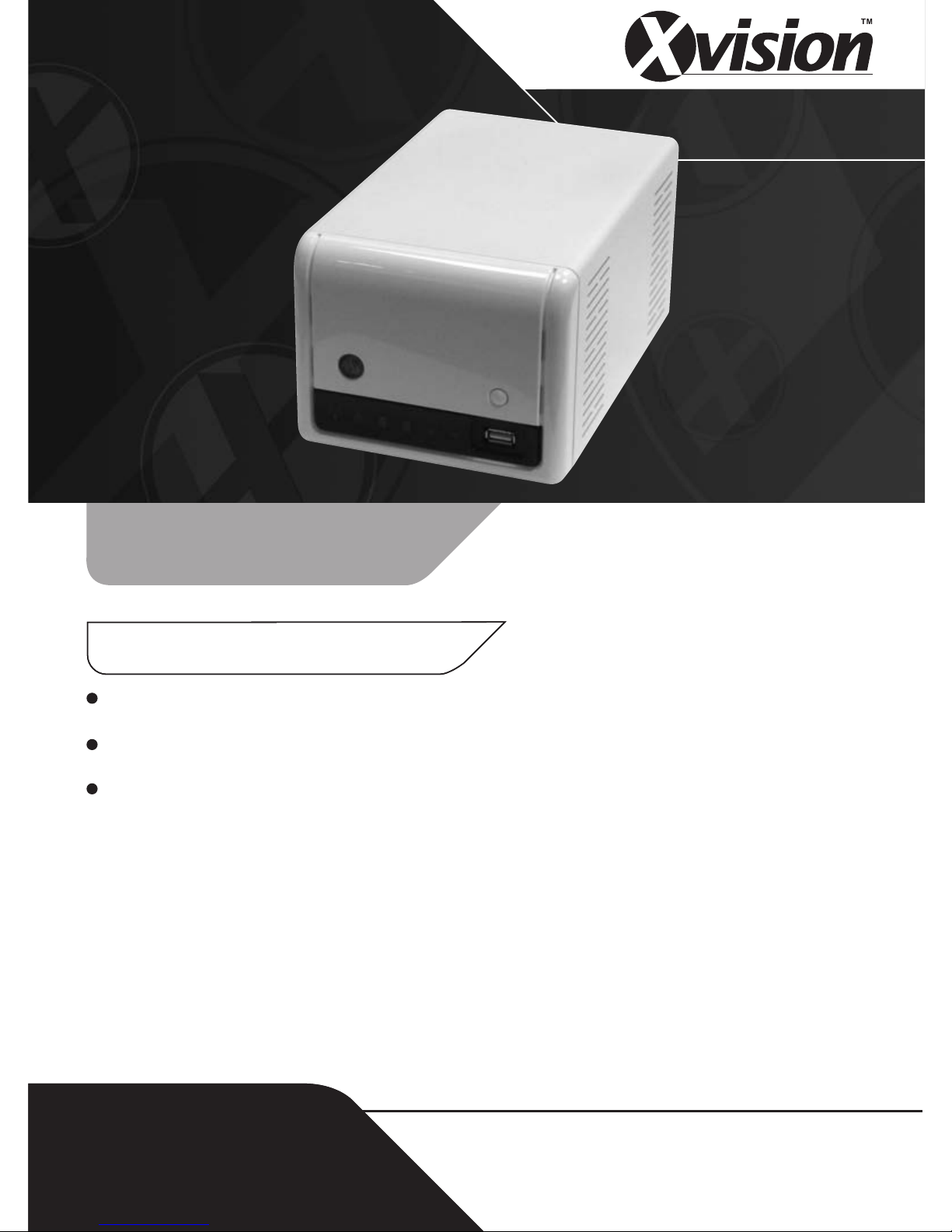
1.2 Getting to Know Your Device
Front View
Power
Button
Unmount
Button
LED Icons
USB Port 1
z Power Button – Press to turn on the device. Press and hold for
about five seconds to turn off. When you press the button to
boot, the button start blinking Blue, and then becomes a steady
Blue when the device is ready.
z Unmount Button (USB Port 1) – Press to safely remove the
connected USB device on the USB Port 1.
z USB Port 1 – Connect the external USB device.
z LED Icons – The LED icons on the front panel let you know the
related status of your device. See the following table for more
information of the LED icons.
-4-
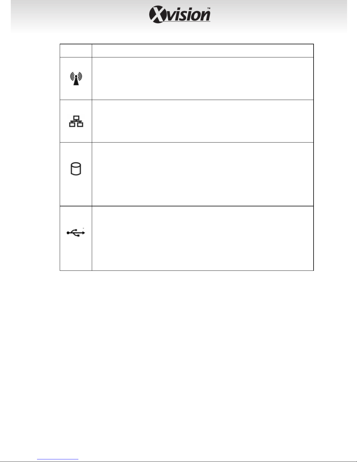
Icon Description
A steady Green light indicates the device is connected to
your wireless network. When it blinks, the device is
receiving/transmitting data from/to the wireless
network.
A steady Green (1000 Mbps) or Amber (10/100 Mbps)
light indicates the device is connected to your LAN.
When it blinks, the device is receiving/ transmitting data
from/to the network.
A steady Green light indicates the hard disk drive is
installed in the device. A blinking Green light indicates
the installed hard disk drive is reading/writing data.
1/2
A steady Amber light indicates the hard disk drive is
complete full (100%). A blinking Amber light indicates
the hard disk drive is getting full (95%).
The LED off indicates no USB devices is connected to the
device.
When you connect the USB device to the device, the LED
1/2
becomes a steady Green light.
When it blinks, the device is receiving/ transmitting data
from/to the USB device.
-5-
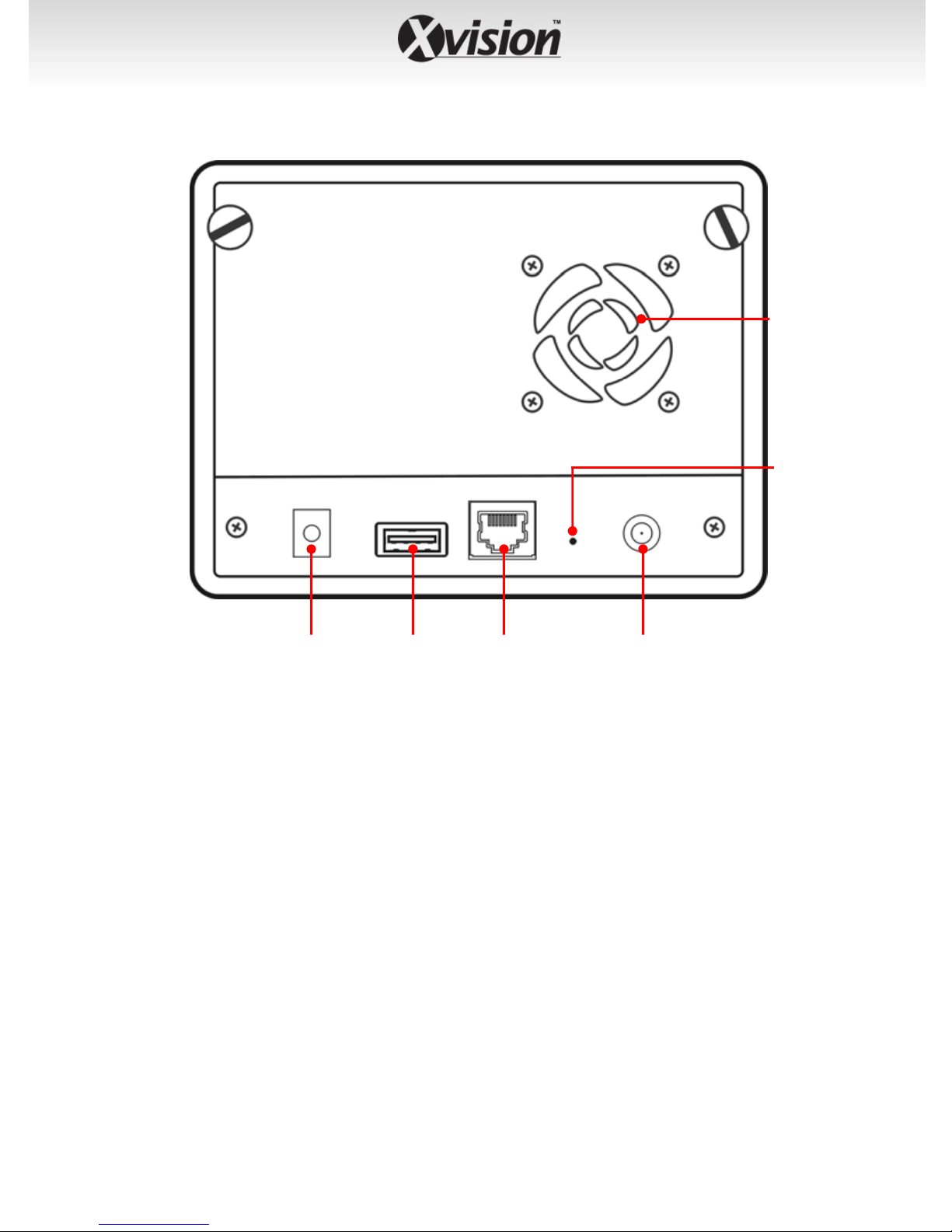
Rear View
Fan and
Ventilator
Reset
Hole
Power
Connector
USB Port 2 Antenna
LAN
Connector
Connector
z Power Connector – Plug the provided AC Power Adapter.
z USB Port 2 – Connect the external USB device. Please note that
this USB port is used for connecting a USB printer only.
z LAN Connector – Plug the provided Ethernet Cable to connect
to your LAN.
z Reset Button – Press to reset the device. Press and hold for
about five seconds to resume the factory default configuration.
z Antenna Connector – Connect the external antenna.
z Fan and Ventilator – Do not block or cover the ventilator for air
circulation.
-6-

1.3 Features and Benefits
Easy to install and use.
Remotely access and manage.
Support auto-setup while connecting up to four cameras.
Simultaneous record the live video streams.
Start recording by manual or by schedule.
The frame rate for alarm recordings can be specified independently
from the frame rate of scheduled recordings. Different video sources
can have different frame rates for scheduled recordings.
Support up to two SATA hard disk drives (SATA II is recommended).
-7-
CHAPTER 2
HARDWARE INSTALLATION
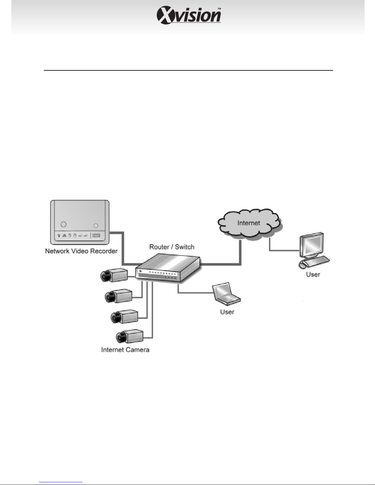
2.1 Networking Application
The following diagram explains the application of the Wireless Network
Video Recorder within your network. In the illustration below, the
Wireless Network Video Recorder and four Internet cameras are
connected to a router/ switch, which minimize the impact of the network
traffic for the users within the network.
Network Video Recorder in your networking environment
-8-

2.2 Installing the Hard Disk Drive
1. Disconnect the power cable of the device.
2. Remove two screws on the rear
panel, and then remove the rear
panel.
3. Pull the bracket out from the disk bay.
4. Place the hard disk drive on the bracket, and then secured with two
screws.
NOTE While placing the hard disk drive onto the bracket, align the
screw holes on the bottom of hard disk drive with the studs
on the base of bracket. The two studs are designed to
ensure the hard disk drive will be installed on the bracket
securely.
5. Push the bracket into the disk bay all the way until it connects the
device.
6. Replace the rear panel and secure two screws.
-9-

2.3 Connecting the Network
t
y
W
t
Connecting to LAN
Plug an Ethernet cable to the LAN
connector located on the device’s
rear panel, and then connect it to
he network or directly to a
computer for configuration.
Connecting to WLAN
When you use the device within
our wireless network, you need to
attach the included external
antenna to the device.
hen the device is powered on,
he camera will automatically
search any access point with
“default” SSID.
NOTE If the device cannot to your wireless network, you need to install
the device in LAN and proceed with WLAN settings.
-10-

2.4 Connecting the Power Adapter
Plug the AC power adapter to the power connector located on the
device’s rear panel, and then connect it to your local power supply.
-11-

CHAPTER 3
ACCESSING THE DEVICE
3.1 Accessing the device via My Network Places
Since you have built a connection between the device and your PC, you
can easily access the device via My Network Places.
1. On your PC, click Start > My
Network Places.
2. Find the device with its device named (such as NVRxxxx) in My
Network Place.
-12-

3. Double-click the device icon. When the login window appears, enter
the User name (the default is admin) and password (the default is
admin), and then click OK to access the Wireless Network Video
Recorder.
TIP If you connect an USB device to the device, it will be shown in the
window.
-13-

3.2 Using IPFinder
The device comes with a conveniently utility, IPFinder, which is included
in the Installation CD-ROM, allowing you to search the device on your
network easily.
1. Insert the Installation CD-ROM into your PC’s CD-ROM drive to
initiate the Auto-Run program.
2. Click the IPFinder item to launch the utility. The control panel will
appear as below.
Display the connected device(s).
Double click to link the device.
Click About to get the Version information of IPFinder.
Click Link to connect the selected device.
Click Change IP to modify the IP address of the selected device.
Click Search to find the IP address of the connected device(s).
Click Exit to close the utility.
3. Once you get the IP address of the device, launch the Web browser
to access your device.
-14-
CHAPTER 4
CONFIGURING THE DEVICE
You can easily access and manage the Wireless Network Video Recorder
via the Web browser of your PC. This chapter describes the Web
Configuration Utility, and guides you through the configuration of the
device.
Since the default configuration of the device is DHCP mode enabled, you
are recommended to use IPFinder to search the IP address that is
assigned to the device by the DHCP server, and then click Link to access
the camera via the Web browser.
Alternately, you can launch the Web browser and then manually enter
the IP address (the default is 192.168.0.20) in the Address bar and press
ENTER to access the Web Configuration Utility.
-15-
4.1 Using the Setup Wizard
The device’s Setup Wizard lets you configure your device easily and
quickly. The wizard will guide you through the necessary settings stepby-step.
To start the wizard, click Setup Wizard in the menu bar.
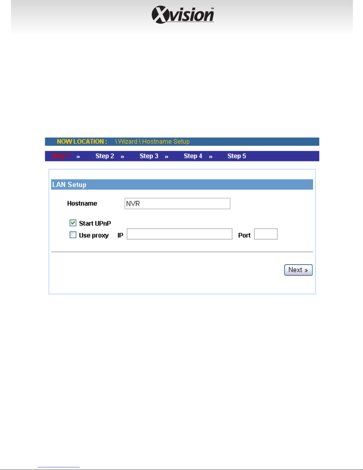
Step 1. LAN Setup
z Enter the Hostname for the device.
z Select Start UPnP to enable the device’s Universal Plug and Play
function.
z If your network uses a proxy server, select Use proxy and enter
the IP/Port values.
-16-
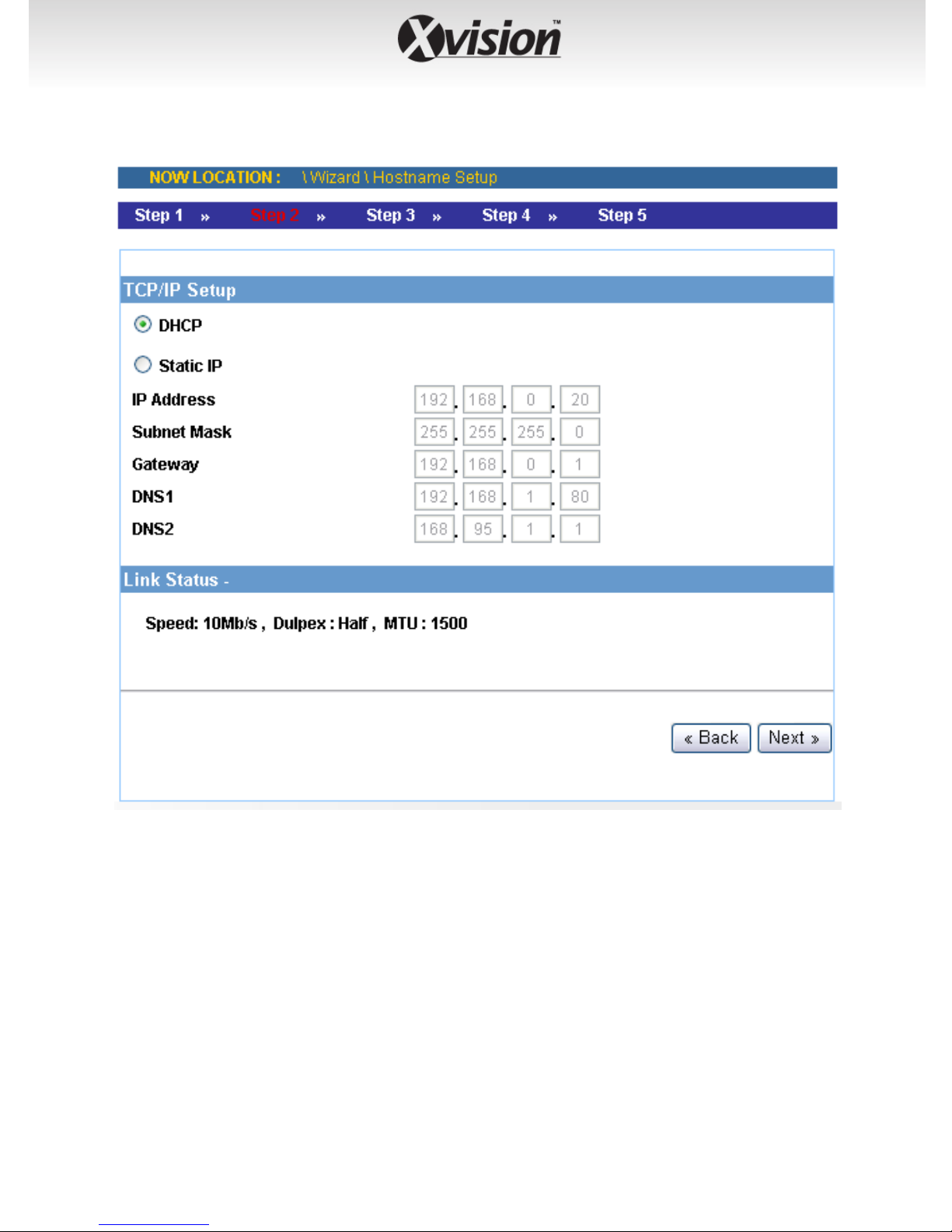
Step 2. TCP/IP Setup
z Select DHCP when your network uses the DHCP server; or select
Static IP to assign the IP address for the device directly.
For more information of TCP/IP settings, refer to the Lan section
in Web Configuration Utility.
-17-
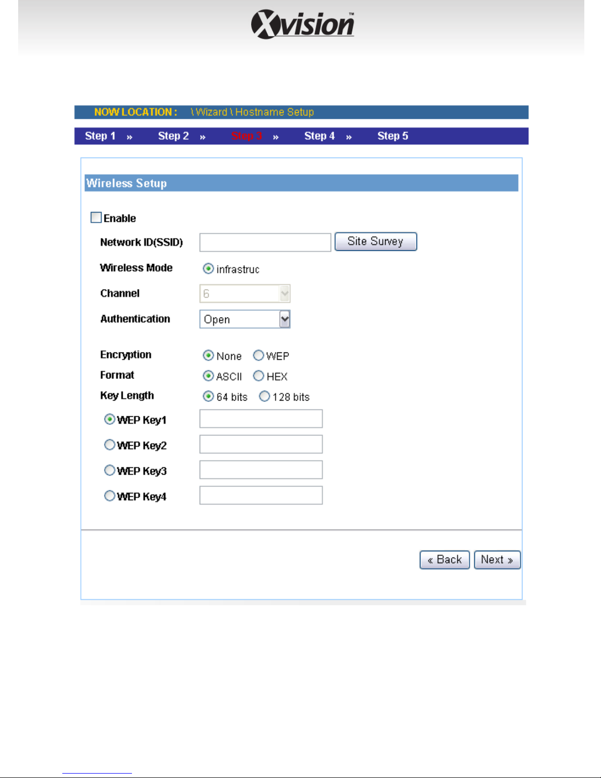
Step 3. Wireless Setup
z Select Enable and complete the required settings for wireless
networking.
For more information of wireless settings, refer to the Wireless
section in Web Configuration Utility.
-18-
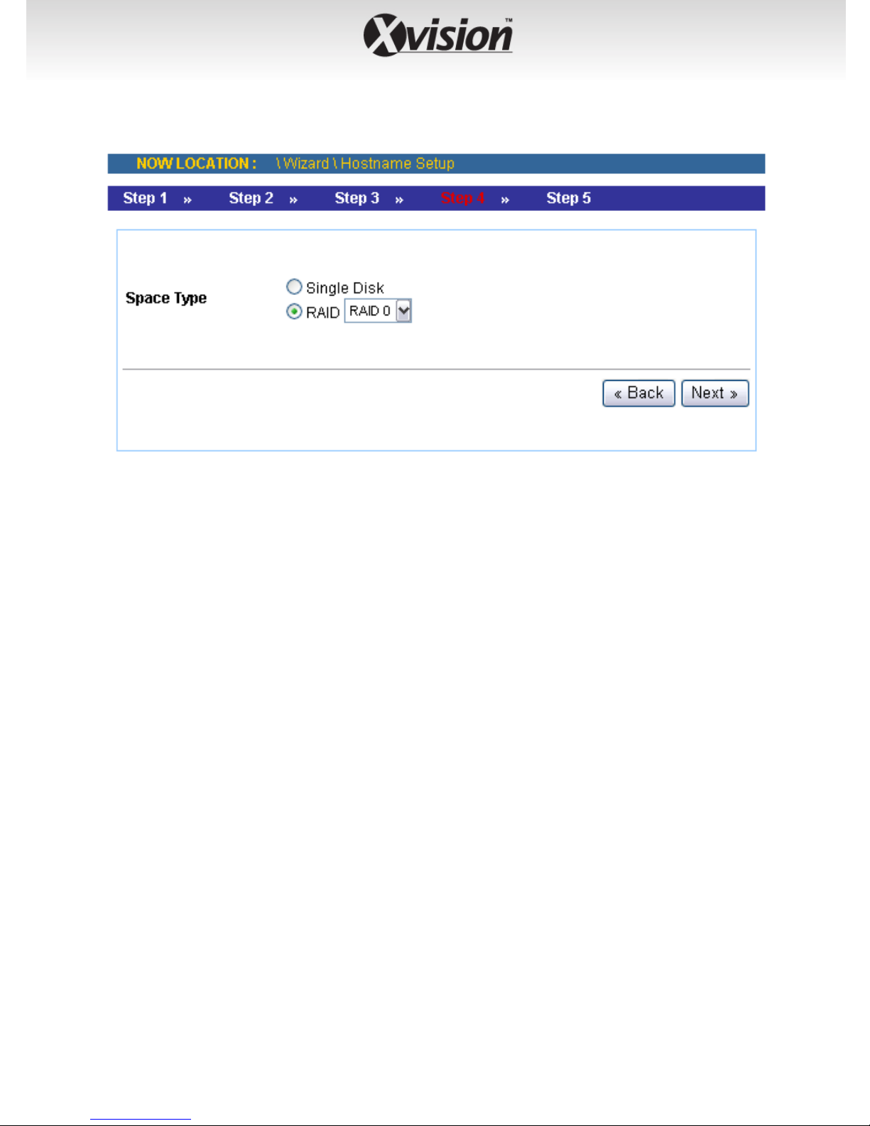
Step 4. Set up Space Type
z Select Single Disk or RAID for storing the files.
For more information of space type, refer to the Storage Setup
section in Web Configuration Utility.
-19-
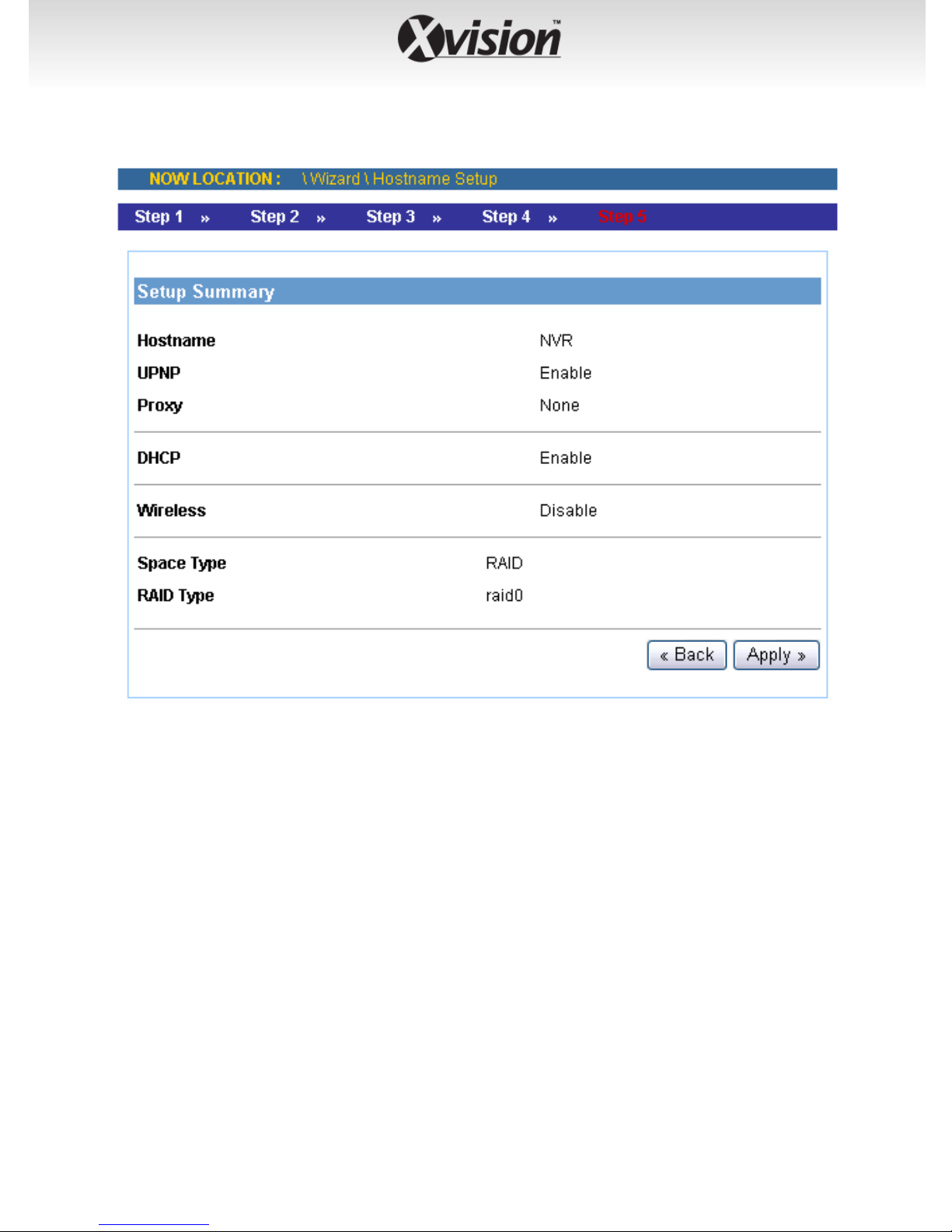
Step 5. Setup Summary
z Display the configuration of the device.
When you complete the Setup Wizard, click Apply to reboot the device.
Otherwise, click Back to go back to the previous step(s) and change the
settings.
-20-
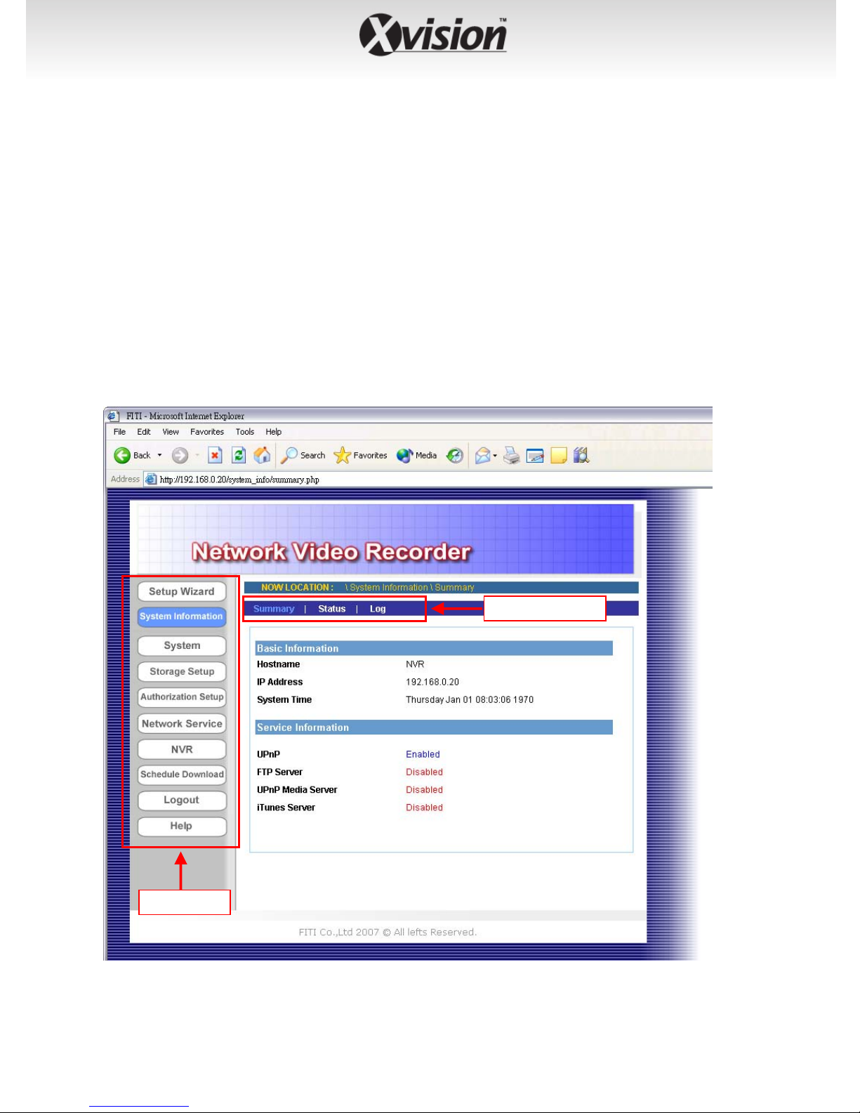
4.2 Using the Web Configuration Utility
After completing the Setup Wizard and rebooting the device, you can
start to use the Wireless Network Video Recorder within your network
environment. However, you can configure the advanced settings through
the Web Configuration Utility.
The utility contains the following options in the menu bar: System
Information, System, Storage Setup, Authorization Setup, Network
Service, NVR, Schedule Download, Logout, and Help. Each option
provides several related settings in the sub-menu area. Click the desired
option from the menu bar and then select the related setting to set up.
Sub-menu area
Menu bar
-21-
4.2.1 System Information
The System Information menu displays the current configuration and
events log of the device.
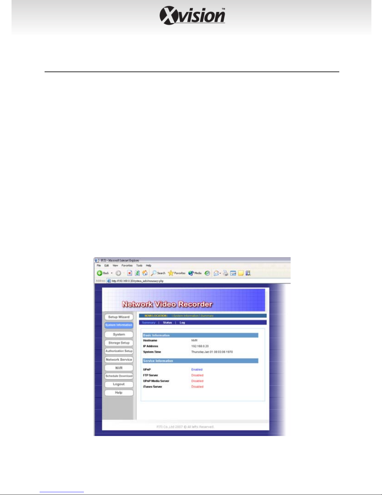
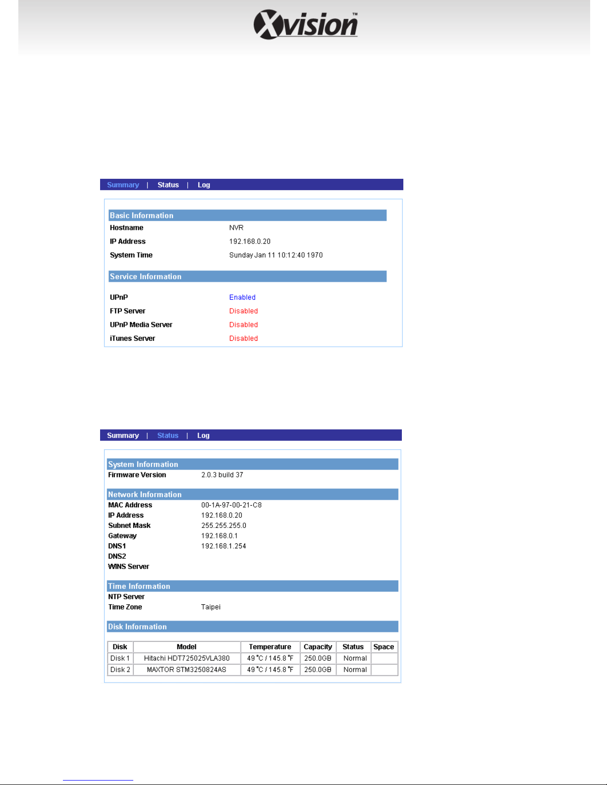
Summary
This sub-menu displays the hostname and IP address of the device,
the date and time, and the network service that you have set up.
Status
-22-
This sub-menu displays the firmware version of the device, the
networking information, the time zone, and the disk information.
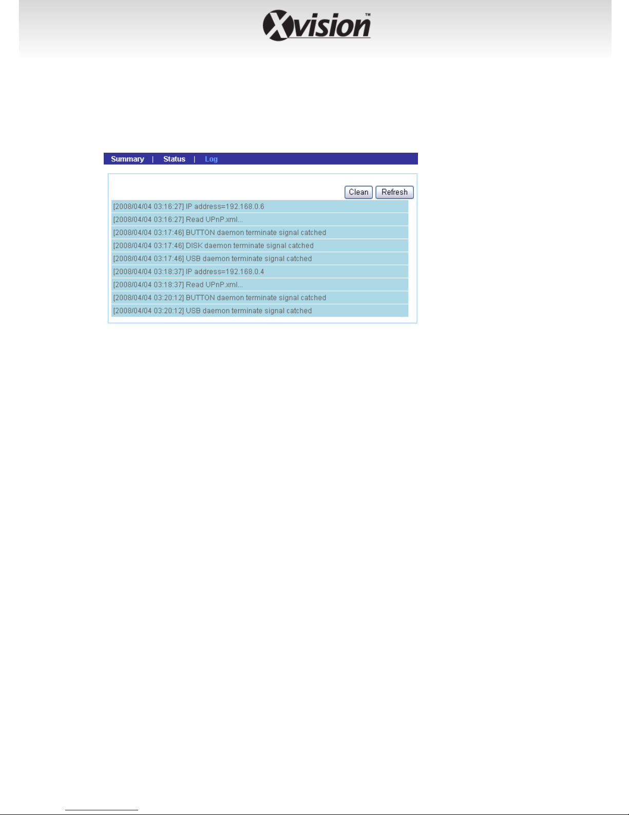
Log
This sub-menu displays the events log recorded by the system.
-23-
4.2.2 System
The System menu contains the basic system settings for the device, such
as the networking settings, time and date setup, etc.
-24-

Lan
z LAN Setup
- Hostname: Enter a descriptive name for the device.
- Start UPnP: The device supports UPnP (Universal Plug and
Play), which is a set of computer network protocols that
enable the device-to-device interoperability. In addition, it
supports port auto mapping function so that you can access
the device if it is behind an NAT router or firewall. Select the
Enable option to enable this feature.
- Use proxy: If your network uses a proxy server, select the Use
proxy option and then enter the IP/Port values.
z TCP/IP Setup
- DHCP: Select this option when your network uses the DHCP
server. When the device starts up, it will be assigned an IP
address from the DHCP server automatically.
-25-

- Static IP: Select this option to assign the IP address for the
device manually. You can use IPFinder to obtain the related
setting values.
IP Address
Subnet Mask
Gateway
DNS 1/2
z Link Status
Display the connection status of the device.
Wireless
Enter the IP address of the device. The default
setting is: 192.168.0.20.
Enter the Subnet Mask of the device. The default
setting is: 255.255.255.0.
Enter the default Gateway of the device. The
default setting is: 192.168.0.1.
DNS (Domain Name System) translates domain
names into IP addresses. Enter the Primary DNS
and Secondary DNS that are provided by ISP.
-26-

The device supports WLAN while you use the wireless network.
Select the Enable option to enable this feature.
z Network ID (SSID)
Keep the default setting of this option to connect the device to
any access point under the infrastructure network mode. To
connect the device to a specified access point, set a SSID for the
device to correspond with the access point’s ESS-ID.
Click Site Survey to display the available wireless networks, so
that you can easily connect to one of the listed wireless networks.
z Wireless Mode
Set the Infrastructure type for wireless communication.
z Channel
Select the appropriate channel from the list.
z Authentication
Select the authentication method to secure the device from
being used by unauthorized user: Open, Shared-key, WPA-PSK,
and WPA2-PSK. The following table explains the four options:
- Open: The default setting of Authentication mode, which
communicates the key across the network.
- DHCP: Allow communication only with other devices with
identical WEP settings.
- DHCP: WPA-PSK/WPA2-PSK is specially designed for the users
who do not have access to network authentication servers.
The user has to manually enter the starting password in their
access point or gateway, as well as in each PC on the wireless
network.
If you select Open or Shared-key as the Authentication mode,
you need to complete the following settings:
- Encryption: Select the WEP option to enable the data
encryption feature to secure the device within the wireless
network.
-27-

- Format: Once you enable the Encryption feature, you need to
determine the encryption format by selecting ASCII or HEX.
ASCII format causes each character you type to be interpreted
as an eight-bit value. Hex format causes each pair of characters
you type to be interpreted as an eight-bit value in
hexadecimal (base 16) notation.
- Key Length: Select the WEP key length you use: 64 bits or 128
bits.
- WEP Key: Enter the WEP key(s) in the four WEP Key boxes.
If you select WPA-PSK or WPA2-PSK as the Authentication
mode, you need to complete the following settings:
- Encryption: Select TKIP or AES. TKIP (Temporal Key Integrity
Protocol) changes the temporal key every 10,000 packets to
insure much greater security than the standard WEP security.
AES (Advanced Encryption Standard) is used to ensure the
highest degree of security and authenticity for digital
information.
- Pre-Shared Key: This is used to identify each other in the
network. Enter the name in the box, and this name must
match the Pre-shared key value in the remote device.
-28-

Time
z Time Zone
Select the proper time zone for the region from the pull-down
menu.
z NTP Setup
Select this option and the time will be synchronized with the
NTP Server. When you select this option, you have to enter the IP
address of the NTP server.
z Manual Setup
Select this option to set the date and time manually.
z Get time from my computer
Click the button and the date & time settings of the device will
be synchronized with the connected computer.
Once you complete the time and date setup, click Apply.
-29-

Notification
This sub-menu contains the required settings for e-mail notification
feature. When you complete the settings, click Send a test mail to
test the related configuration is correct or not. Once the device
connects to the server successfully, click Apply.
z SMTP Server
Enter the mail server (e.g. mymail.com) in the box. Then, select
the Authorization check box and complete the following
settings:
- User ID: Enter the user name to login the mail server.
- Password: Enter the password to login the mail server.
- Confirm Password: Enter the password again for
confirmation.
z Sender E-mail
Enter the email address of the user (e.g. john@mymail.com) who
will send the email.
-30-
z Primary/Secondary E-mail
Enter the first and second email address of the user who will
receive the email.
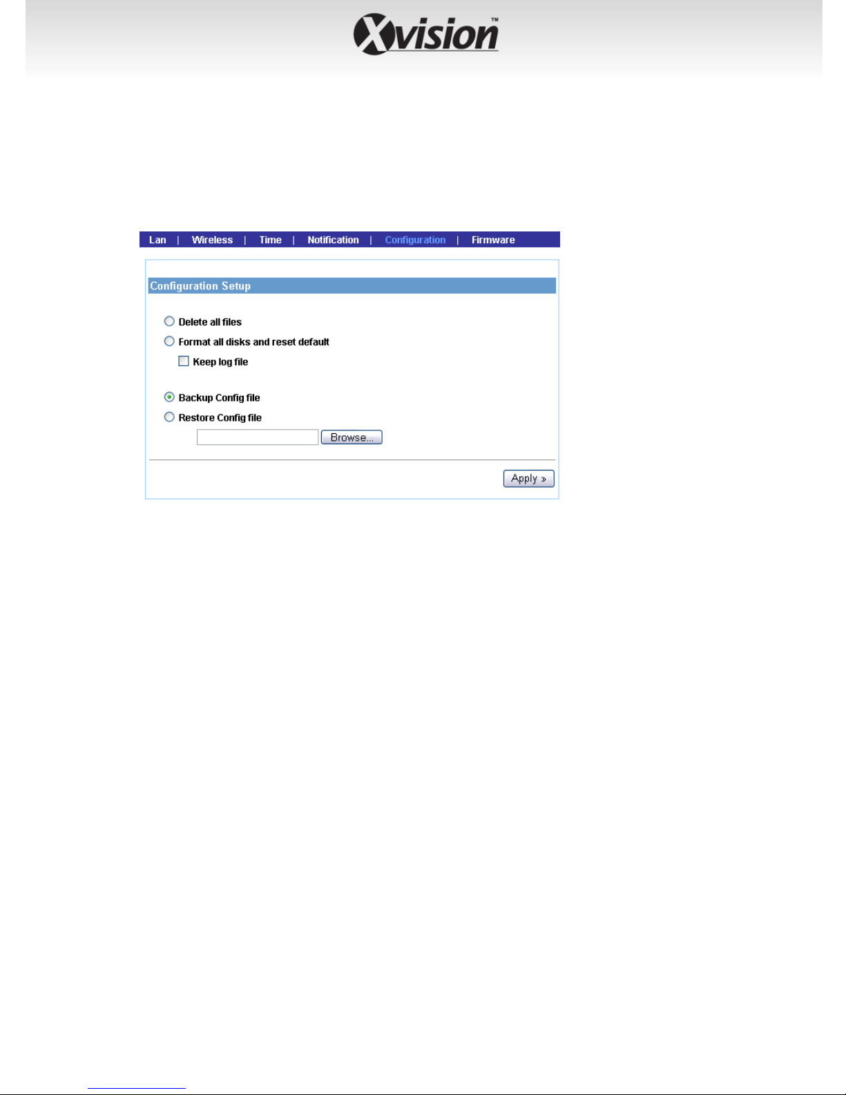
Configuration
z Delete all files
Select this option and click Apply to delete all files stored on the
installed hard disk drives.
z Format all disks and reset default
Select this option and click Apply to format the installed hard
disk drives and reset the device to the default configuration.
Select the Keep log file check box to save the log file when reset.
z Backup Config file
Select this option and click Apply to save the current
customized configuration of the device as a file on your PC.
z Restore Config file
Click Browse to find the configuration file, and then click Apply
to restore the customized configuration.
-31-
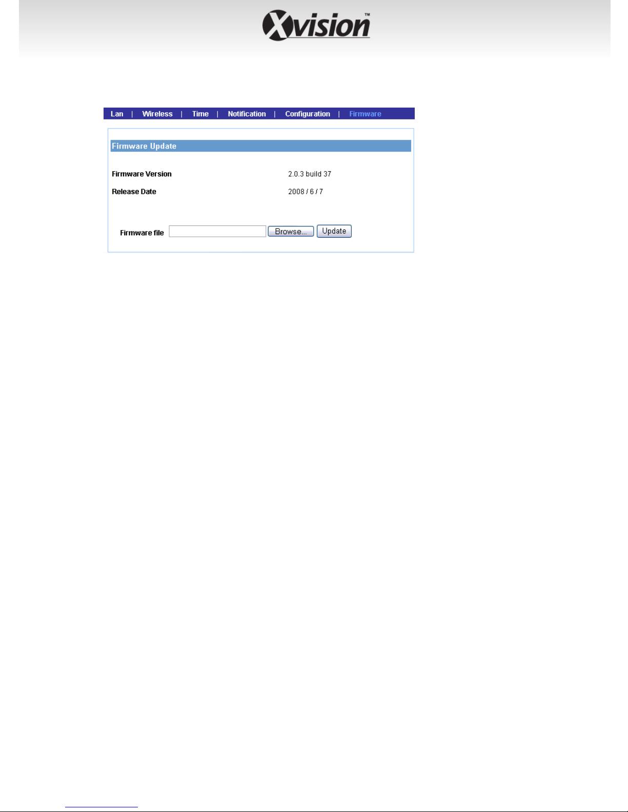
Firmware
This sub-menu displays the firmware version of the device. In
addition, you can upgrade the firmware once you have a latest
version of firmware.
z Firmware file
Click Browse to find the firmware file and click Update.
NOTE Make sure to keep the device connected to the power source
during the process of updating firmware. Otherwise, the device
might be damaged because of failure of updating firmware.
-32-
4.2.3 Storage Setup
The Storage Setup menu provides the information and controls of the
installed hard disk drives, including the USB device.
NOTE You are not recommended to use the USB device as your major
storage device.
-33-
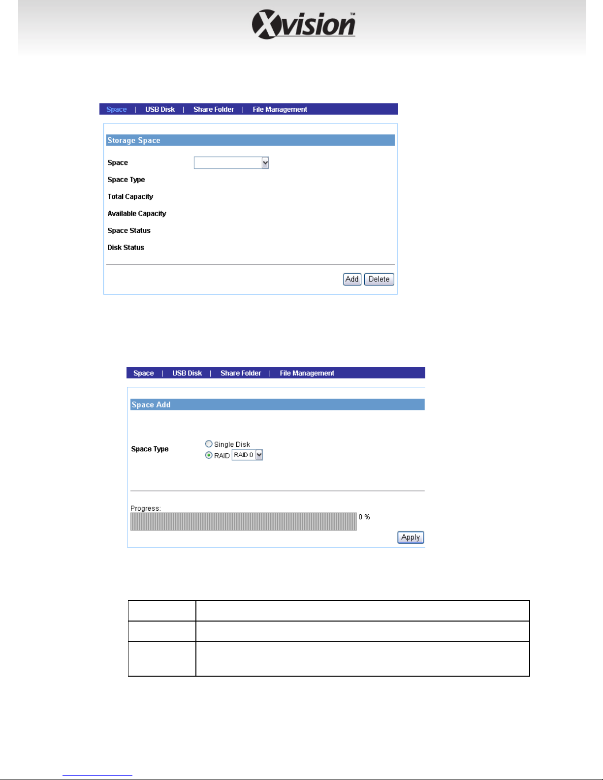
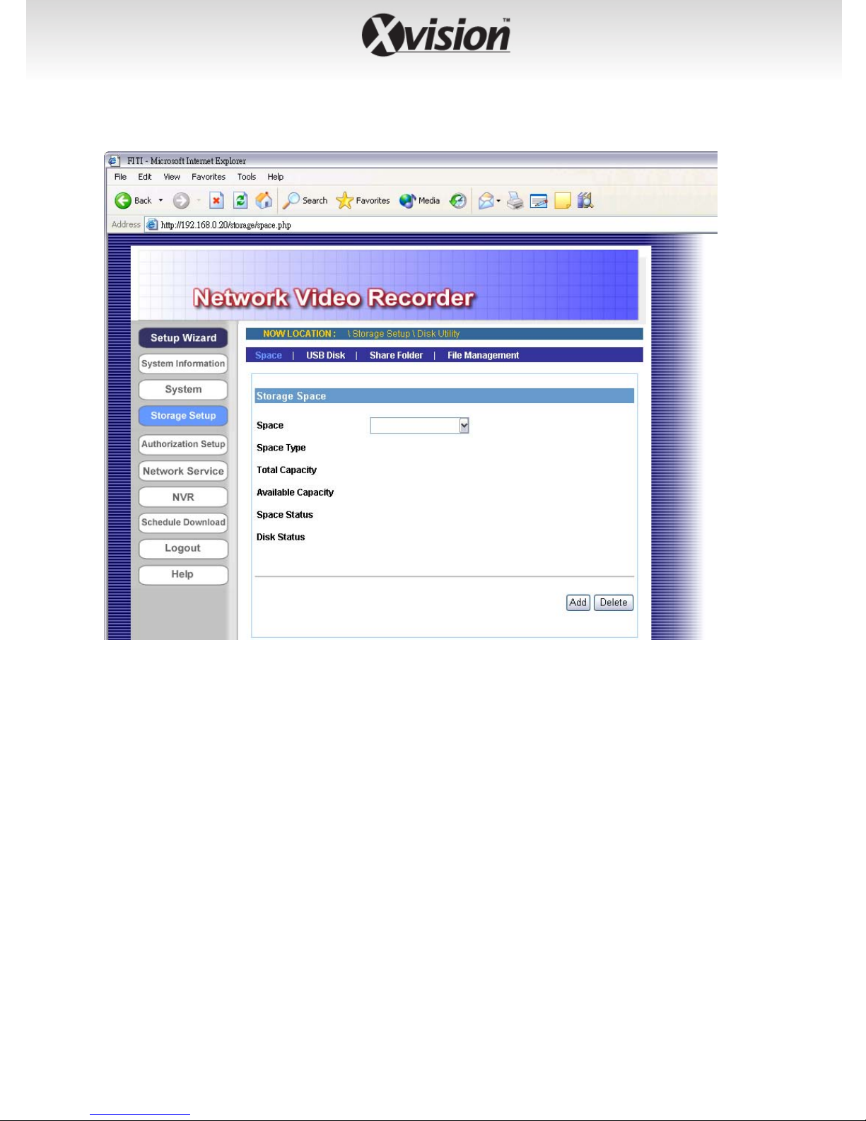
Space
Click Add to configure the storage space on the installed hard disk
drives: selecting Single Disk or RAID. Then, click Apply to start
making file system.
If you have two hard disks installed in the device, you can select
a disk configuration for RAID:
RAID 0
RAID 1
JBOD
(not recommended) Provide data striping.
(recommended) Provide mirroring over both disks.
(maximum data storage space) Combine both drives in
a linear fashion to create one volume.
-34-
When completed, the related information of the disks is
displayed on the screen.
Click Add to add a storage space, or click Delete to remove the
current storage space.
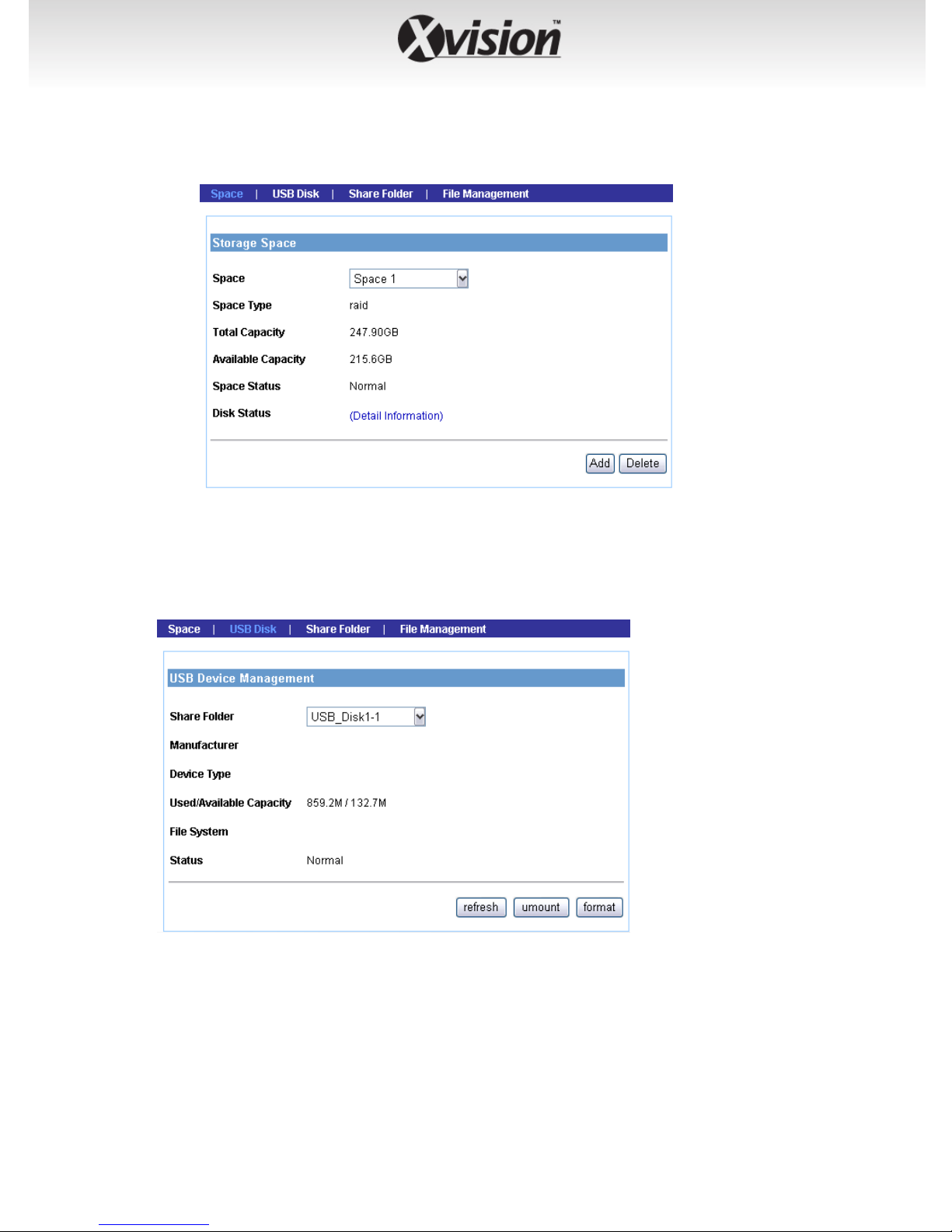
USB Disk
If you connect an external USB disk, this sub-menu displays the
information of the USB disk.
To safely remove the connected USB device, click unmount from this
sub-menu. (The other way is pressing the Unmount button on the
front panel of the device for disconnecting the USB Port 1.)
-35-
To reload the information of the connected USB devices, click
refresh.
Click format to format the connected USB disk.
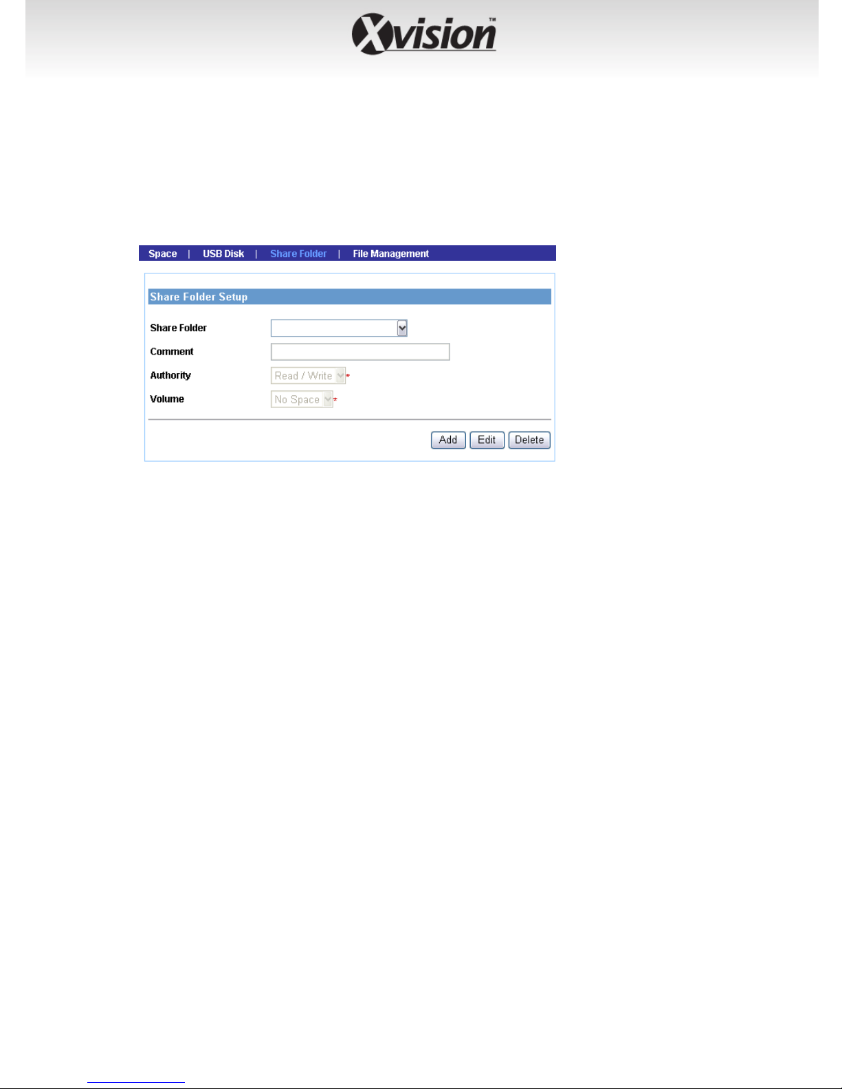
Share Folder
This sub-menu allows you to specify the shared folder of the disks.
Click Add and then assign the destination folder from the Share
Folder list and give a brief instruction in the Comment box.
The Authority option allows the administrator to limit the usage of
the shared folder. Select the authority type (Read/Write or Read Only)
from the list to meet your need.
Finally, assign the storage location from the Volume list.
When completed, click Apply to add the folder that you assigned.
You can then use the File Explorer on your PC to check the folder that
will be displayed as the directory under the device name.
To change the setting, select the folder from the Share folder list
and then click Edit. To remove, select it and then click Delete.
-36-
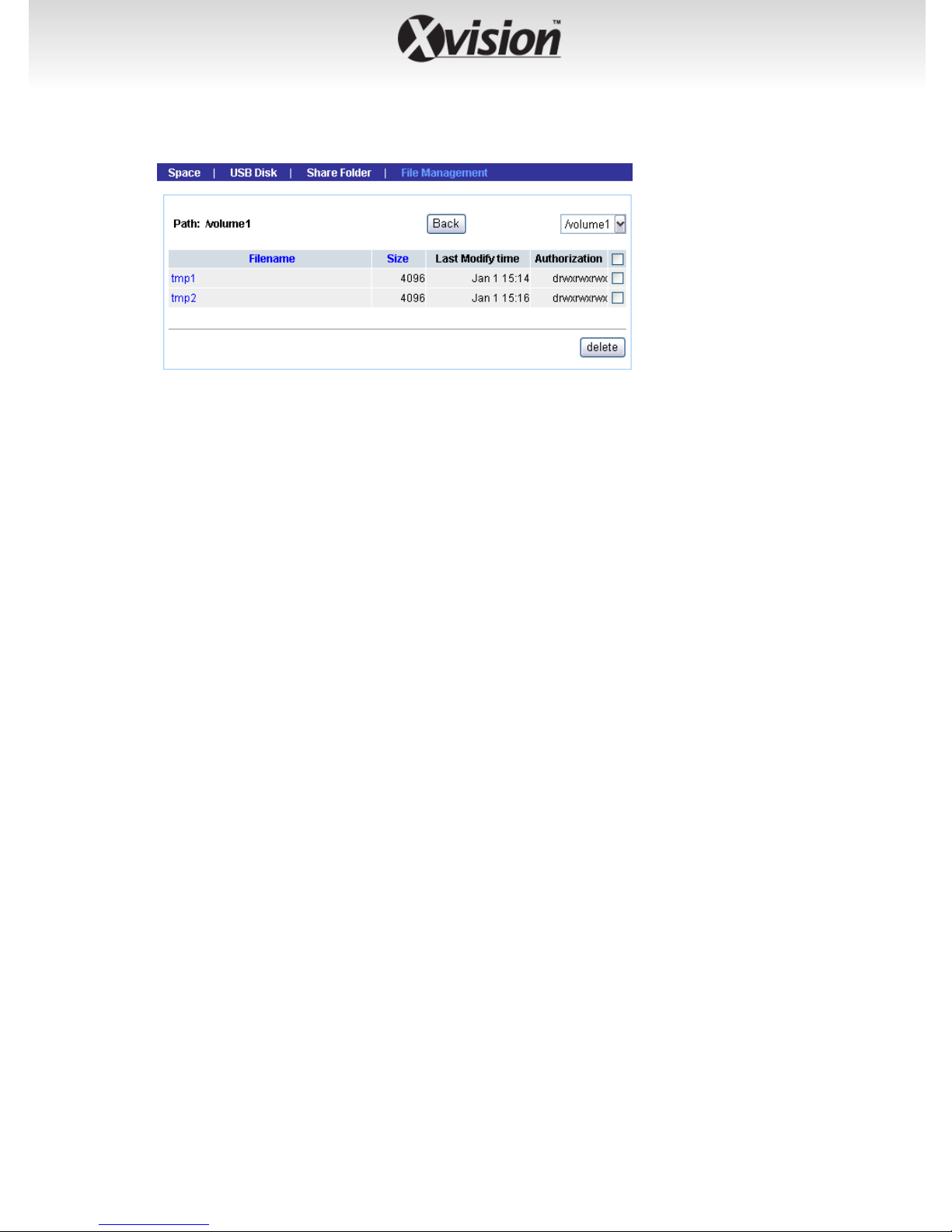
File Management
This sub-menu displays the log of file system that you have made in
the device.
-37-
4.2.4 Authorization Setup
The Authorization Setup menu allows you to manage the users and
groups of the device.
-38-
User
Click Add and then assign the user name in the Select User box, and
give a brief instruction in the User Description box.
If you have set up groups for organization, you can assign the user to
a group from the Group list.
Enter the password twice for the new user in the Password and
Confirm Password boxes, and then select the Permission type
(Admin or User).
Specify the storage quotas for the user from the Quota option of
Space Status.
When completed, click Apply to add the user. You can change the
user’s setting by selecting the user and then clicking Edit, or remove
the user by selecting the user and then clicking Delete.
-39-
Group
Click Add and then assign the group name in the Group Name box,
and then you can add/remove users for the group from the Member
option.
When completed, click Apply to add the group. To organize the
users for the group, click Edit Member. To remove the group, select
it from the list and then click Delete.
-40-

Authorization
This sub-menu displays the assigned access rules and quotas of the
users and groups.
-41-

4.2.5 Network Service
The Network Service menu allows you to set up the network services for
the device, such as FTP server, UPnP media server, etc.
Windows OS
-42-

z Windows Network Setup
- Workgroup: Enter the workgroup name where the device is
installed within your network.
- WINS Server: WINS (Windows Internet Name Service) server is
used to support NetBIOS over TCP/IP (NetBT). Enter the IP
address of the WINS server in the box, otherwise you cannot
connect to a remote network resource by using its NetBIOS
name.
z Codepage
Select the proper Language to set the correct character for
codepage.
FTP
This sub-menu contains the options that allow you to enable/disable
the FTP service of the device.
-43-

z Start FTP Service
Select this option to enable the FTP server of the device. Once
you start the FTP service, you should assign the FTP Port (the
default is port 21) and select to switch to the PASV mode or not.
z User transmission limitation
Specify the maximum upload and download speed (KB/s) by
entering the proper values in the related boxes.
z allow Anonymous
Selecting this option will allow the user to connect to the FTP
server anonymously.
UPnP Media Server
The device supports UPnP (Universal Plug and Play) and port auto
mapping function so that you can access the device if it is behind an
NAT router or firewall. Select this option to enable the UPnP media
server and then assign the Path from the list.
iTunes Server
-44-

The device features an iTunes Server. It provides the ability to share
files to the computer on the local network running iTunes. If the
function is enabled, the device will be automatically detected in the
iTunes program and the files contained in the specified directory will
be available to stream over the network.
Select this option to enable the iTune server and then assign the
Path from the list. You can also set up the Use Password to avoid
unauthorized access.
USB Printer (only when an USB printer is connected)
When you connect an USB printer to the USB Port 2 of the device,
this sub-menu displays the information of the USB printer.
-45-

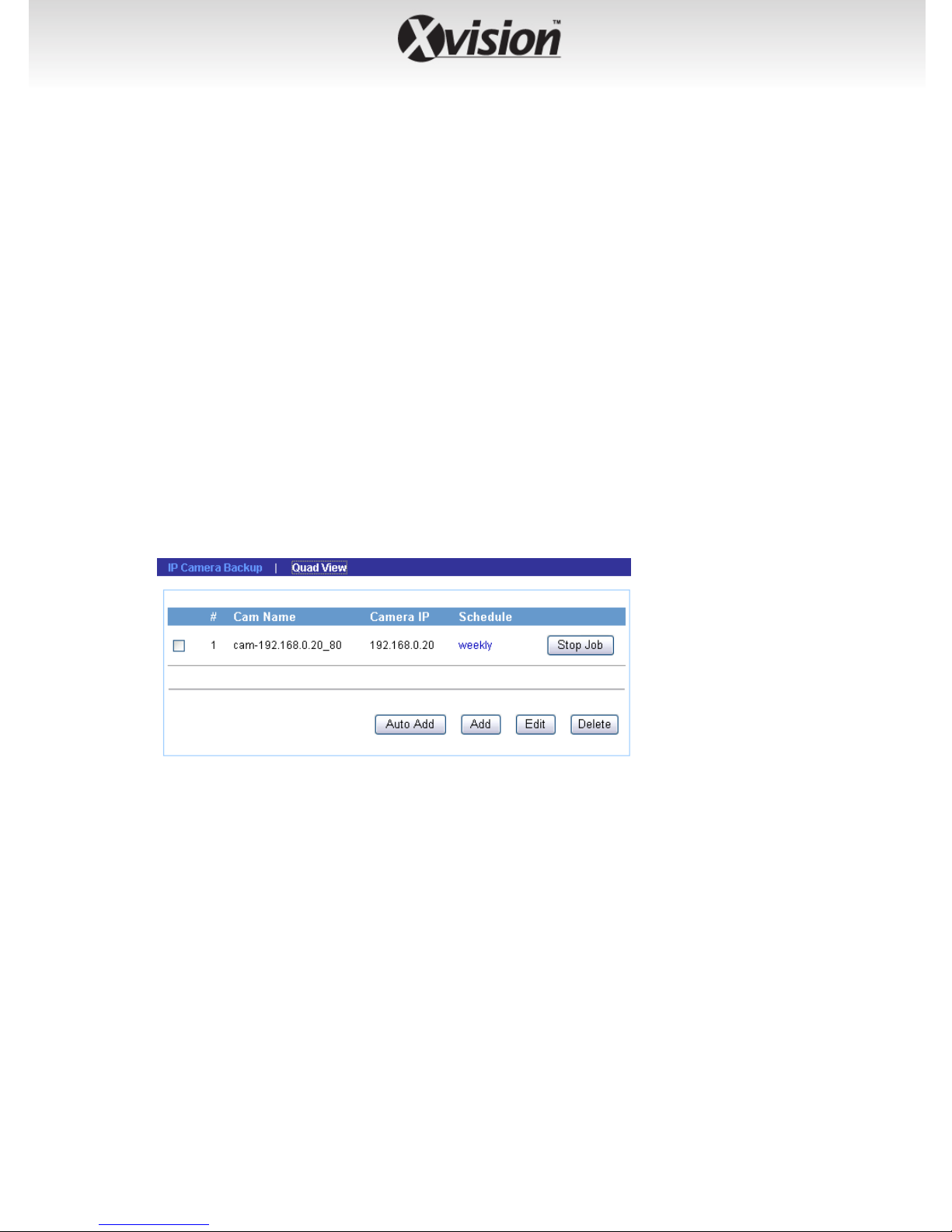
4.2.6 NVR
The NVR menu allows you to add Internet cameras and view the live
video.
IP Camera Backup
Click Auto Add to add the camera automatically, or click Add and to
add the camera manually through the following setup window:
-46-
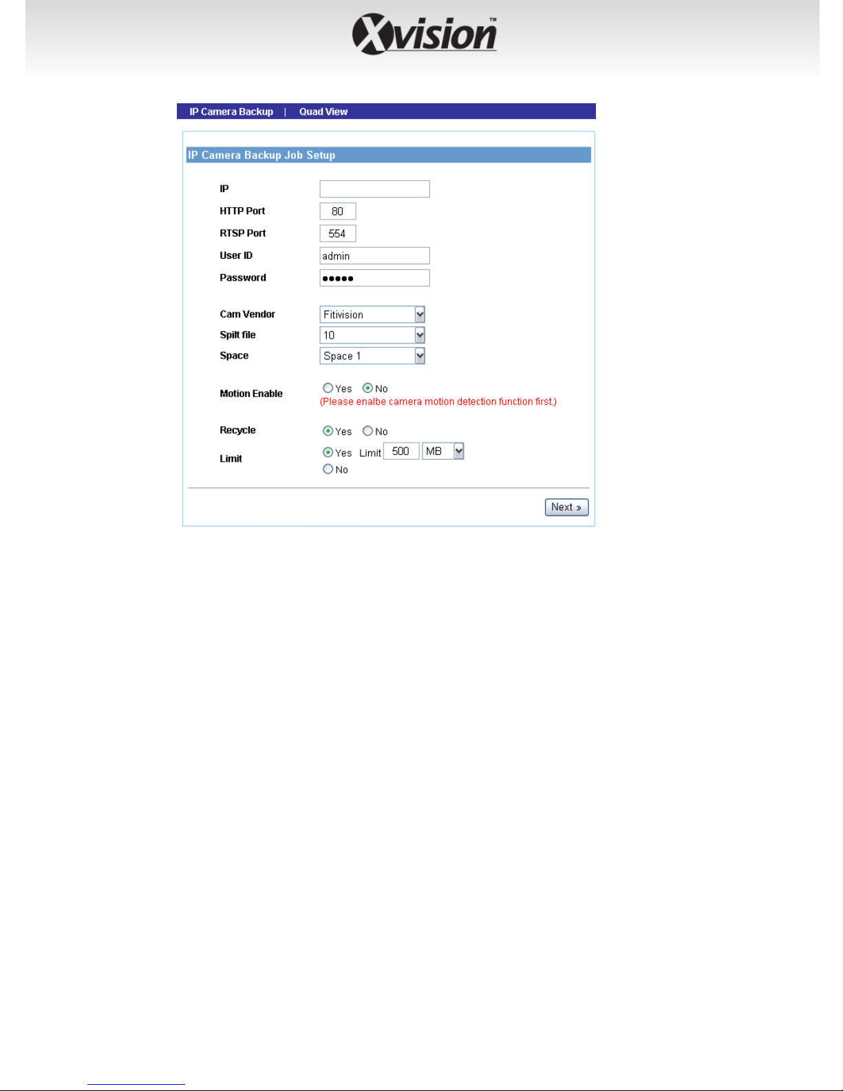
z IP
Enter the IP address of the camera.
z HTTP Port
Assign the HTTP Port for the camera (the default is 80).
z RTSP Port
Configure the transmission of streaming data within the network.
The default RTSP (Real Time Streaming Protocol) port is 554.
z User ID/Password
Enter the user name and password for accessing the camera.
z Cam Vendor
Select the manufacturer of the camera from the list.
z Split file
When the recorded file is too large, use this option to split it by
selecting file size.
-47-
z Space
Specify the storage space for the camera.
z Motion Enable
Enable of disable the motion detection of the camera (if have).
z Recycle
Enable of disable the recycling function when the storage space
on the device is full.
z Limit
Select Yes to limit the recording file by specifying the storage
volume from the list. Otherwise, select No to record without
limitation.
When completed, click Next to set up the schedule for using the camera,
and then click Apply to add it to the list.
You can then change the configuration of the camera by selecting it
from the list and then clicking Edit. To remove a camera, select it and
then click Delete.
-48-
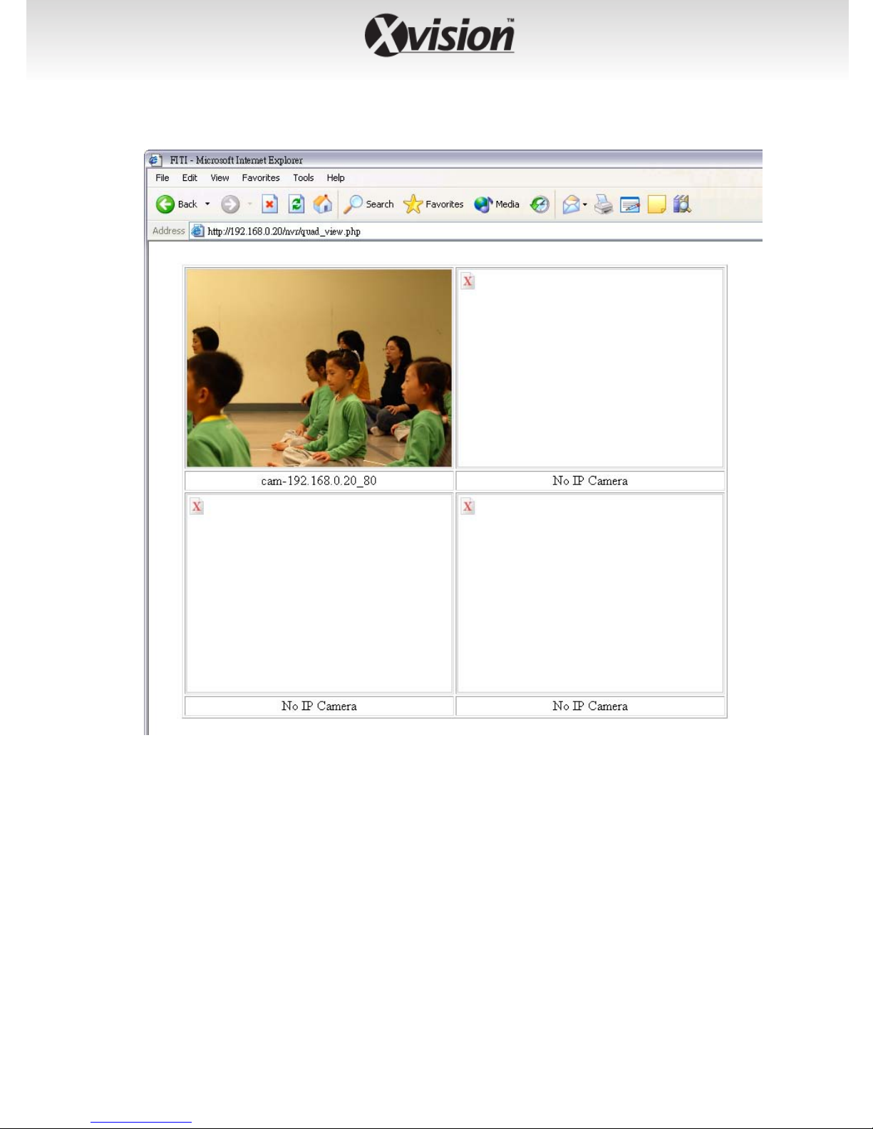
Quad View
In the Quad View screen, you can view the live video from the
connected camera. You can view up to four cameras simultaneously.
-49-
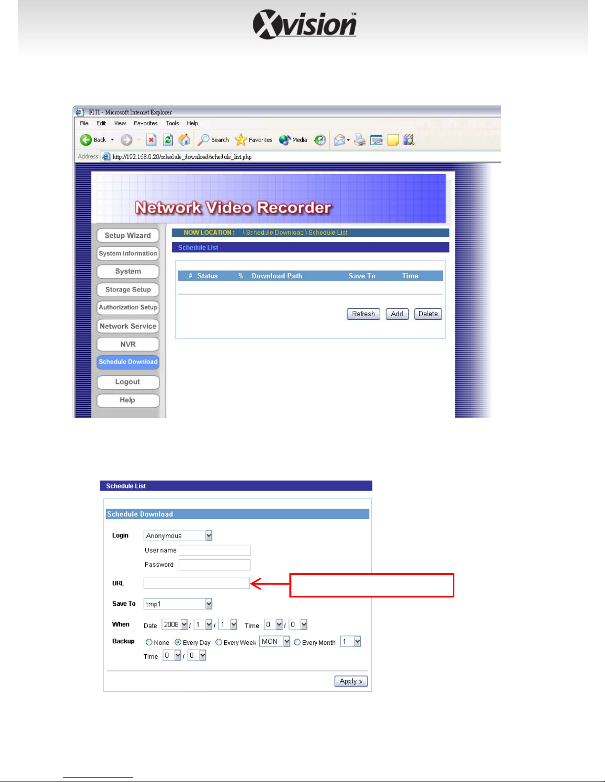
4.2.7 Schedule Download
The Schedule Download menu allows you to set up download schedule.
Click Add and the following setup window will appear:
Please input the file name.
-50-

z Login
Select Anonymous or Account from the list according to the
settings of the target server. If you have to select Account to
login, you should enter the correct User name and Password.
z URL
Enter the URL address of target server.
z Save To
Assign the destination folder from the list to save the
downloaded files.
z When
From the Date and Time setting options, set up the start-up
time to download files.
z Backup
Enable the backup function of your device by selecting None,
Every Day, Every Week, or Every Month, as well as the Time.
When completed, click Apply to save this download task to the Schedule
List.
You can delete the download task by selecting it from the Schedule List
and then clicking Delete. When you change the settings of selected task,
click Refresh to reload the status of these tasks.
-51-

4.2.8 Logout
The Logout menu allows you to exit or shutdown the system.
Logout
From this sub-menu, click Apply to exit the Web Configuration Utility
and go back to the Login window.
-52-
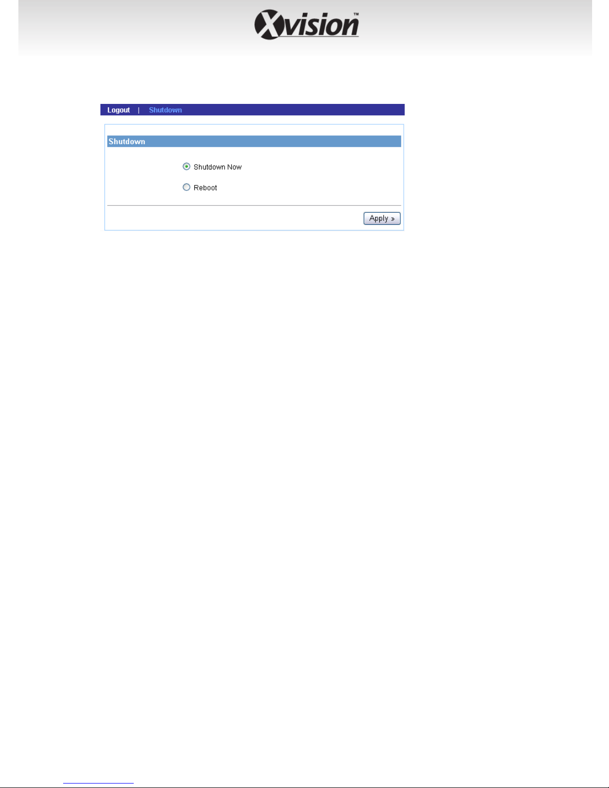
Shutdown
From this sub-menu, you can do one of the following:
z Select Shutdown Now and click Apply to turn off the device.
z Select Reboot and click Apply to reboot the device.
-53-
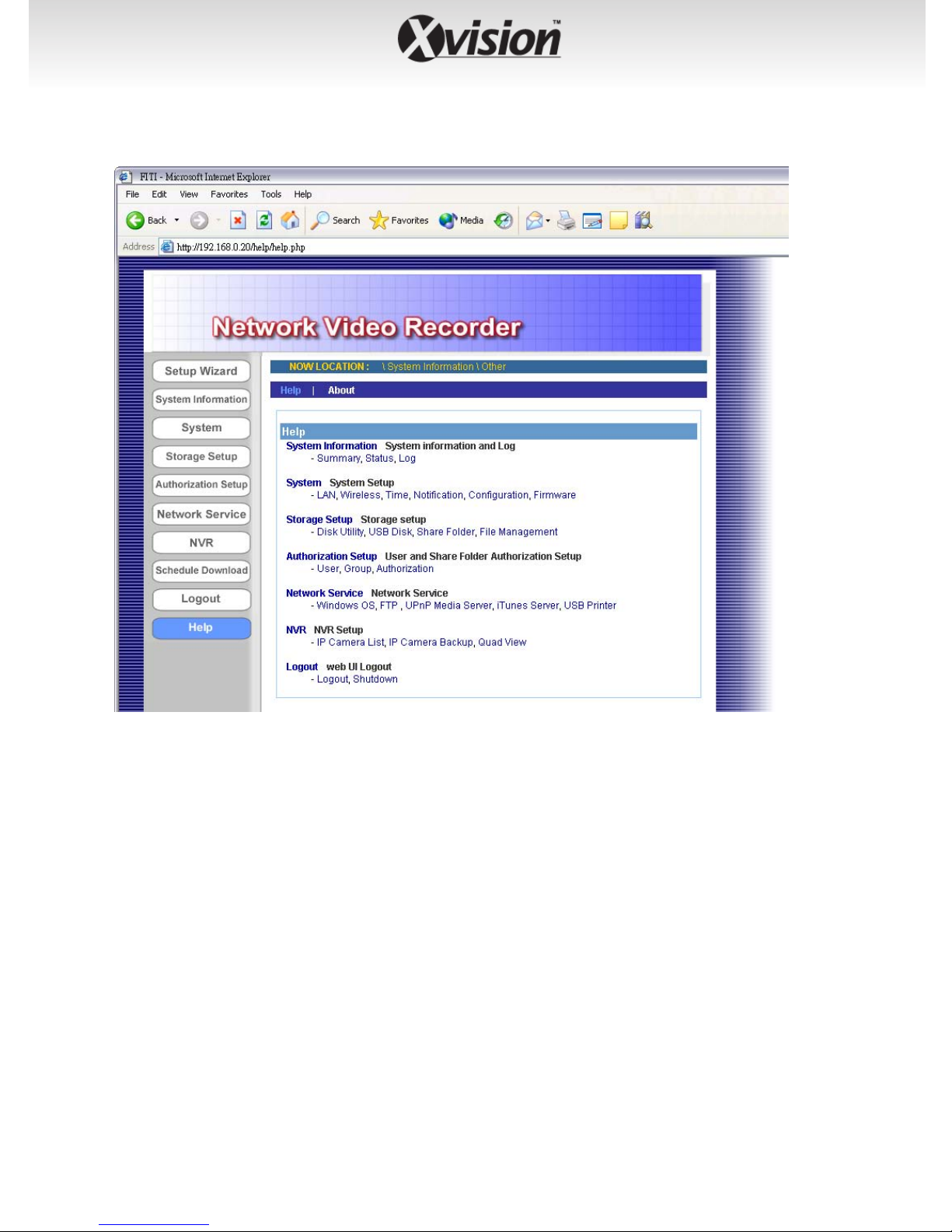
4.2.9 Help
The Help menu displays the information for each setting option of the
device. Click the topic (marked as blue color) to link to the corresponding
page and view the related information in detail.
-54-

APPENDIX
Specifications
System Hardware
Microprocessor ARM9, Storlink 3516
ROM 16MB Flash ROM
RAM 128MB DDR SDRAM
Power Requirement DC 12V, 4A, 100-240V; auto-sensing
Hard Disk Drive
HDD Type SATA (I/II)
Disk Bay 2
HDD Configuration Standard, RAD0, RAD1, JBOD
RTC Yes
User Interface
Connectors One power connector, one Ethernet
connector (RJ-45 port), two USB 2.0 ports,
one antenna connector
Buttons One Power button, one Reset button,
one Unmount button
LED Icons WLAN, LAN, HDD x 2, USB x 2.
Communication
LAN 10/100/1000Mbps Fast Ethernet/Giganet,
auto-sensed
WLAN IEEE 802.11b/g
Protocol support TCP/IP
Physical Specification
Dimension 201 x 134 x 205 mm
Weight 1.74 kg
-55-

Operating Environment
Temperature - Operation: 0°C ~ 40°C
- Storage: -10°C ~ 70°C
Humidity - Operation: 10% ~ 85% non-condensing
- Storage: 5% ~ 90% non-condensing
EMI
FCC Part 15 Class B, CE, VCCI
-56-

Notes

Notes

CCTV
TECHNICAL SUPPORT:
For Technical Support for any Xvision product please contact your local
distributor.
LIMITED WARRANTY:
This product is supplied with a 1 Year warranty. The Warranty excludes
products that have been misused, (including accidental damage) and
damage caused by normal wear and tear. In the unlikely event that you
encounter a problem with this product, it should be returned to the
place of purchase.
CCTV
Manufactured exclusively for:
Xvision (Europe) Group,
Head Office: London, U.K.
Email: info@x-vision.co.uk
Web: www.x-vision.co.uk
 Loading...