


USER MANUAL
SAFETY INSTRUCTION ....................................................................................................................................... 5
CHAPTER 1 PRODUCT OVERVIEW .......................................................................................................... 1
1.1 REAR PANEL ............................................................................................................................................... 1
1.2 REMOTE CONTROLLER (FOR REFERENCE ONLY ) ........................................................................................................ 2
CHAPTER 2 NVR INSTALLATION & CONNECTION ................................................................................ 3
2.1 HDD INSTALLATION ............................................................................................................................................ 3
2.2 CONNECTION DIAGRAM ...................................................................................................................................... 4
2.3 POWER SUPPLY CONNECTION ............................................................................................................................... 4
CHAPTER 3 NVR COMMON OPERATIONS .............................................................................................. 5
3.1 USING THE SUPPLIED MOUSE ............................................................................................................................... 5
3.2 USING THE VIRTUAL KEYBOARD ............................................................................................................................ 5
3.3 PASSWORD ....................................................................................................................................................... 6
CHAPTER 4 NVR STARTING UP ................................................................................................................ 7
4.1 START WIZARD .................................................................................................................................................. 7
4.1.1 Start Wizard ........................................................................................................................................... 7
4.1.2 Network Configuration .......................................................................................................................... 7
4.1.3 Date/Time .............................................................................................................................................. 8
4.1.4 IP Camera ............................................................................................................................................. 10
4.1.5 Disk ...................................................................................................................................................... 12
4.1.6 Resolution ............................................................................................................................................ 12
4.1.7 Mobile .................................................................................................................................................. 13
4.1.8 Summary .............................................................................................................................................. 13
4.2 LIVE VIEW SCREEN OVERVIEW ............................................................................................................................ 14
4.2.1 Camera Quick Toolbar .......................................................................................................................... 15
4.2.2 Taskbar ................................................................................................................................................. 16
4.2.3 Start Menu ........................................................................................................................................... 17
4.2.3.1 Unlock and Lock Screen .................................................................................................................................. 17
4.2.3.2 Shutdown ....................................................................................................................................................... 17
CHAPTER 5 NVR SYSTEM SETUP .......................................................................................................... 18
5.1 CHANNEL........................................................................................................................................................ 19
5.1.1 IP Channels ........................................................................................................................................................ 19
5.1.2 Protocol Manage ............................................................................................................................................... 20
5.1.2 Live ....................................................................................................................................................... 21
5.1.3 Image Control ...................................................................................................................................... 23
5.1.4 PTZ ....................................................................................................................................................... 25
5.1.4.1 PTZ control ...................................................................................................................................................... 26
5.1.5 Motion ................................................................................................................................................. 27
5.1.6 Alarm ................................................................................................................................................... 28
5.1.7 Video Cover .......................................................................................................................................... 29
5.1.8 Intelligent ............................................................................................................................................. 30
5.1.8.1 PID (Perimeter Intrusion Detection) ............................................................................................................... 30

USER MANUAL
5.1.8.2 LCD (Line Crossing Detection) ......................................................................................................................... 32
5.1.8.3 SOD (Stationary Object Detection) ................................................................................................................. 34
5.1.8.4 PD (Pedestrian Detection) .............................................................................................................................. 36
5.1.8.5 FD (Face Detection) ........................................................................................................................................ 38
5.1.8.6 CC (Cross-Counting) ........................................................................................................................................ 40
5.1.8.7 Intelligent Analysis .......................................................................................................................................... 43
5.1.8.8 Intelligent Schedule ........................................................................................................................................ 43
5.2 RECORD ......................................................................................................................................................... 44
5.2.1 Encode .................................................................................................................................................. 44
5.2.2 Record .................................................................................................................................................. 45
5.2.2.1 Record............................................................................................................................................................. 45
5.2.2.2 Record Schedule ............................................................................................................................................. 46
5.2.3 Capture ................................................................................................................................................ 47
5.2.3.1 Capture ........................................................................................................................................................... 47
5.2.3.2 Capture Schedule............................................................................................................................................ 48
5.3 ALARM........................................................................................................................................................... 49
5.3.1 Motion ................................................................................................................................................. 49
5.3.2 I/O ........................................................................................................................................................ 49
5.3.3 PTZ Linkage .......................................................................................................................................... 50
5.3.4 Exception .............................................................................................................................................. 50
5.4 NETWORK....................................................................................................................................................... 51
5.4.1 General ................................................................................................................................................ 52
5.4.4.1 PPPoE .............................................................................................................................................................. 53
5.4.1.3 Port Configuration .......................................................................................................................................... 53
5.4.2 DDNS .................................................................................................................................................... 54
5.4.3 Email .................................................................................................................................................... 55
5.4.3.1 Email Configuration ........................................................................................................................................ 55
5.4.3.2 Email Schedule ............................................................................................................................................... 56
5.4.4 FTP ............................................................................................................................................................ 57
5. 5 DEVICE .......................................................................................................................................................... 57
5. 5.1 Disk...................................................................................................................................................... 58
5.5.1.1 Disk Group ...................................................................................................................................................... 60
5.5.1.2 S.M.A.R.T ........................................................................................................................................................ 61
5.6 SYSTEM .......................................................................................................................................................... 62
5.6.1 General ................................................................................................................................................ 62
5.6.1.1 Date and Time ................................................................................................................................................ 63
5.6.1.2 NTP Settings .................................................................................................................................................... 64
5.6.1.3 DST Settings .................................................................................................................................................... 64
5.6.2 Output Configuration ........................................................................................................................... 65
5.6.2.1 LIVE-OUT ......................................................................................................................................................... 66
5.6.3 Multi-user ............................................................................................................................................ 67
5.6.3.1 Changing Password ......................................................................................................................................... 67
5.6.3.2 Add New Users ............................................................................................................................................... 68
5.6.3.3 Setting User Permissions ................................................................................................................................ 69
5.6.4 Maintenance ........................................................................................................................................ 70

USER MANUAL
5.6.4.1 Log .................................................................................................................................................................. 70
5.6.4.2 Load Default ................................................................................................................................................... 71
5.6.4.3 Upgrade .......................................................................................................................................................... 72
5.6.4.4 Parameter Management ................................................................................................................................. 72
5.6.4.5 Auto Reboot ................................................................................................................................................... 73
5.6.5 IP Camera Maintain ............................................................................................................................. 73
5.6.5.1 Upgrade IP Camera ......................................................................................................................................... 74
5.6.5.2 Load Default Settings for IP Camera ............................................................................................................... 74
5.6.6 System Information .............................................................................................................................. 75
5.6.6.1 Information ..................................................................................................................................................... 75
5.6.6.2 Channel Information ....................................................................................................................................... 75
5.6.6.3 Record Information ......................................................................................................................................... 76
5.6.6.4 Network State ................................................................................................................................................. 76
CHAPTER 6 SEARCH, PLAYBACK & BACKUP .................................................................................... 77
6.1 USING SEARCH FUNCTION ................................................................................................................................. 77
6.1.1 Search & Play Video in General ............................................................................................................ 79
6.1.1.1 Video Clip Backup ........................................................................................................................................... 79
6.1.2 Event Search, Playback & Backup ........................................................................................................ 81
6.1.2.1 Event Playback Control ................................................................................................................................... 82
6.1.3 Sub-periods Playback ........................................................................................................................... 83
6.1.4 Picture Search & View .......................................................................................................................... 84
6.1.5.1 Picture Preview Control .................................................................................................................................. 85
CHAPTER 7 REMOTE ACCESS VIA WEB CLIENT ............................................................................... 86
7.1 BASIC SYSTEM ENVIRONMENT REQUIREMENTS ...................................................................................................... 86
7.2 WEB PLUGIN DOWNLOAD AND INSTA LLAT ION ........................................................................................................ 86
7.3 WEB CLIENT MANAGER ............................................................................................................................... 89
7.3.1 Live Interface ........................................................................................................................................ 89
7.3.2 Playback ............................................................................................................................................... 91
7.3.2.1 Playback Control Buttons ................................................................................................................................ 92
7.3.3 Remote Setting ..................................................................................................................................... 94
7.3.4 Local Setting ......................................................................................................................................... 94
CHAPTER 8 VIEWING BACKED UP VIDEO ON PC/MAC ..................................................................... 95
CHAPTER 9 REMOTE ACCESS VIA MOBILE DEVICES ....................................................................... 98
CHAPTER 10 APPENDIX ......................................................................................................................... 108
10.1 TROUBLESHOOTING ................................................................................................................................. 108
10.2 USAGE MAINTENANCE............................................................................................................................. 109
10.3 ACCESSORIES (FOR REFERENCE ONLY) ..................................................................................................... 110

USER MANUAL
SAFETY INSTRUCTION
Please carefully read the follow ing safety instruction so as to avoid personal injuries and prevent
the equipment and other conne ction devices from being damaged.
1. Power sources (note: pl ease use the power supply attached or specified by t he
manufacturer)
Never operate the equipment by using unspecified power supply.
2. Never push objects of a ny kind through openings of NVR
Never push objects of any kind through openings of NVR so as to avoid electric shock or other
accidents.
3. Do not put the eq ui pment in a dusty environment
Do not put the equipment in a dusty environment.
4. Do not place the equipment under r a in or humid envi r onment
Do not place the equipment under humid environme nt li ke basement. If the equipment is
accidentally in contact with water, please unplug the power cable and immediately cont act your
local dealer.
5. Keep the surface of the equipment clean and dry
Use soft damp cloth to clean the outer case of NVR (do not use liquid aer osol cleaners)
6. Do not operate if any problem s ar e found
If there are any strange smells or sounds from NVR, unplug the power cable and contact the
authorized dealer or servi c e cent er.
7. Do not try to remove the upper cover
Warning
: Do not remove the cover of NVR so as to avoid electric shoc k.
8. Handle with care
If NVR does not work normally because of h it t in g on the hard object, please cont act t he
authorized dealer for repair or r eplace m ent .
9. Use standard lithium batt er y (Note: Use the batteries at t ached or specified by the
manufacturer)
After cutting off the power supply, if the system clock cannot continue to work, please replace
the standard 3V lithium battery on the main board.
Warning:
Turn off NVR before replacing the batteries , or you may be suffered from serious
electric shock. Please pro per ly dispose of the used batteries.
10. Put the equipment in a pl ace with good ventilation
The NVR system includes HDD, which produces large amount of h eat dur ing operation. As a
result, do not block the ventilation open ings (on t he top, bot tom, bot h sides an d the r ever se side)
for cooling the system duri ng operation. Install or put the equi pment in the place with good
ventilation.
11. The att ached power adapter can only be used for 1 se t of NVR. Do not connect more
equipment, or NVR may be restarted repeatedly because of insuf ficient power.
12. Prevent the equipment from wat e r dr opping or splas hing. Do not place obj ects
containing water, such as flower vase, on the equipm ent.

Chapter 1 Product Overview
1.1 Rear Panel
Item Physical Port Connection Method
1
Power Switch
Startup and shutdown
2
Power Port
Connect the attached power supply
3
USB Port
Connect USB devices, such as USB mouse and USB flash disk.
4
Sensor/Alarm
Connect to sensor or alarming device
5
HDMI Port
HDMI high definition port
6
VGA Port
Connect to VGA monitor, such as PC monitor
7
LINE IN
Intercom voice input
8
AUDIO OUTPUT
Audio signal output, RCA int erf ace
9
WAN Port
Network input interface of the router/Connect to IP camera.
10
LAN Port
LAN network interface, support POE, can supply power to the camera.
11
E-SATA
Optional. Connect to e-SATA HDD for recording & backup
1

USER MANUAL
1.2 Remote Controller (For Ref erence Only)
No.
Icon
Description
1 1-8
Numeric keys
Press to display channel 1 ~ 8
2
9
、
0
Numeric keys
3 ALL
Press to display all channels
Multiple display mode
4 Menu Press to enter or exit the Main Menu
5 Mute Mute On/off
6 Submenu Go to submenu
7
Up arrow key; Volume increase
8 SEL
Press to enter the selected me nu it em and
edit the setting
9
Left/Right key; Decrease/ i ncr ease parameter
value of control bar.
10
Down arrow key; Vol ume decrea se
11
Press to rewind during video pl ayback
12
Press to fast forward durin g video playback
13
Press to play recorded video or ent er t he
recording search menu
14
Press to start manual reco r ding
15
Press to stop manual recording or st op the
video playback
16
Press to pause the video play bac k or enter
frame-playback mode
Table 2-1
1
2
3
4
5
6
7
8
9
10
9
11
12
13
14
15
16
2

USER MANUAL
Chapter 2 NVR Installation & Connection
2.1 HDD Installation
This NVR supports two 3.5” or 2.5” SATA hard disk drives.
CAUTION
:
DO NOT install or remove the hard disk drive while the device power is
turned ON
HDD Instal lation:
Note: Above procedures ar e for r ef er ence only. The practical operation may be different
depending on the NVR you pur chased.
a) Connect the data and power cables to the two hard disk
drives and place the hard disk drives on the NVR case.
b) Carefully flip the NVR case and secure the hard disk drives
to the NVR with the eight (8) screws
3

USER MANUAL
2.2 Connection Diagram
Note: Above diagram is for referen ce only. The practical connection may be different depending
on the NVR you purchased.
2.3 Power Supply Connection
Caution: Use only the suppl ied power adapter t hat ca me with the NVR
Connect one end of the p ower ada pter to t he power c onnector on the b ack of th e NVR. Plug the other
end of the power adapter i nto t he wall out let.
For some specific models, you may need to press the Power sw it ch to turn on the power.
Speaker
4

USER MANUAL
Chapter 3 NVR Common Operations
3.1 Using the Supplied Mouse
1.
Left Button:
o
Click to select menu options.
o
During live viewing in sp lit -screen view , double-click on a channel to view it in full-screen.
Double-click the channel again to return to split-screen viewing.
o
Click upon a channel on Live Viewing screen to open Cam era Quick Toolbar.
o
Click and hold to drag sliders and scal es on menu mode
2.
Right Button:
o
Click once to open the Taskbar on the Live Viewing screen. View Taskbar on 4.2.2 Taskbar
o
In menus, click to go back / close men us.
3.
Scroll Wheel:
o
In menus, scroll to move up / dow n through the menu content.
o
While hovering over the volu m e control wheel, scroll to turn system volume up / down.
3.2 Using the Virtual Keyboard
You will see the virtual keyboard automatically on th e scr een w hen you need to enter data
Click to delete a
character
Click to complete
the enter
Click to toggle the keyboar d t o
upper case and more punct uat ion
Move the cursor to left
Move the cursor to right
5

USER MANUAL
3.3 Password
The first time you run the NVR, you will be required to set your own password immediat ely in orde r
to protect your privacy. Please be sure to record your usernam e and password and save them in a
secure place.
Language:
Choose an OSD langua ge
Device ID:
Input the device ID in the parentheses. Default ID is 000000. View more about Devic e
ID on
5.6.1 General
.
New Admin name:
To set your own administrator name.
New Admin Password:
To set your own password. The passw ord must be a combination o f 8
characters.
Corfirm Password:
Enter your own passwor d again.
Click
Apply
to confirm your settings and goes t o t he login interface. Enter your user name &
password to
Login
the NVR system.
NOTE:
If you forget your password, you will be unable to login the
system, please contact your reseller to reset the password.
6

USER MANUAL
Chapter 4 NVR Starting up
4.1 Start Wizard
Startup Wizard will help to configure the system and get the NVR works quickly.
4.1.1 Start W izar d
Click the
Start Wizard
to proceed to the next step
4.1.2 Network Configuration
If you connect to a router that supp or t s DHCP, please check the
DHCP
box. The router w ill assign
automatically all the networ k par ameters for your NVR. If the network is manually addressed use
the below parameters:
IP Address
: The IP address identifies the NVR in the net work. It consists of four groups o f
numbers between 0 to 255, separat ed by periods. For example, “192.168.001.100”.
7

USER MANUAL
Subnet Mask
: Subnet mask is a network par ameter which defines a range of IP addresses that
can be used in a network. If IP address is like a street where you live then subnet mask is like a
neighborhood. The subnet address als o consists of four groups of numbers, separated by periods.
For example, “255.255.000.000”.
Gateway
: This address allows the N VR to access the Internet. The format of the
Gateway
address is the same as the
IP Address
. For example, “192.168.0 01. 001”.
DNS1/DNS2
: DNS1 is the primary DNS server and DNS2 is a backup DNS server. Usually should
be enough just to enter the D NS 1 ser ver address.
Port
Web Port:
This is the port that you will use to log in remotely t o t he N V R (e.g. using the Web
Client). If the default port 80 is already taken by other applicat ion s , ple as e change it.
Client Port:
This is the port that the NVR will use to send informati on t hr ough (e.g. using the
mobile app). If the default port 9000 i s already taken by other applic at io ns, please change it.
RTSP Port:
This is the port that the NVR will be allowed to transm it r eal-time streaming to other
device (e.g. using a streaming Media player.).
UPNP:
If you want to log in remotely to t he N V R using Web Client, you need to complete the port
forwarding in your router. Enable this option if your router supports the U Pn P. In this case, you do
not need to configure manually port forwarding on your router. If your router does not support
UPnP, make sure the port forwarding is com pleted manually in your router.
4.1.3 Date/Time
This menu allows you to configur e the Date, Time, Date Format, T ime Format, Time Zone, NTP
and DST.
Date and Tim e
Click on the calendar icon t o set the current system date.
Date:
Click on the calendar icon to set t he system date.
Time:
Click to set the system tim e.
8

USER MANUAL
Date Format:
Choose from the dropdown menu to set preferred date format.
Time Format:
Choose time format between 24Hour and 12Hour.
Time Zone:
Set the correct time zone.
NTP
NTP stands for Network Time Protocol. This feature allows you to synchronize the date and time
automatically on the NVR ov er Int ernet. Therefor e, the NV R needs to be con nected t o the Internet .
Check the “
NTP
” box, and select the NTP s er ver .
DST
DST stands for Dayli ght Savings Time.
DST
: Enable if Daylight Saving Tim e ( D ST) is observed in your region
Time Offset
: Select the amount of time to offset for DST
Time Mode
: Choose to set the daylight sav in g time in weeks or in days
Start Time/End Time
: Set the start time and end tim e for daylight saving
9

USER MANUAL
4.1.4 IP Camera
This menu allows you to add IP cameras to the NVR.
Click
Search
to search IP ca meras in the same network. Cho os e t he I P camera(s) you w ant t o
add, and then click
icon to add to the NVR.
Enter the camera’s user name & pa s sw or d t o add the camera(s).
You can also click button to add individual IP camera to a single ch annel.
10

USER MANUAL
Click
Search
button to search IP cameras, and then click one of the IP camer a in the device list.
IP Address/D omain:
IP address or domain name of the IP camera
Alias:
Name of the IP ca mera
Position:
Position to display t he camera name on the screen.
Port:
Port of the IP camera
Protocol:
Choose the protocol of the I P camera from the dropdow n menu
Private – indicates X2C and X3C series can connect t o int er net aut omatically via <Private>
Onvif – indicates an open industr y standard prot oco l est ablis hed by Open Netw ork Video Inter face
Focum, and connect to the device of other manufactur er via <Onvif>
Custom – Consider for integrations protocol
User Name:
User Name of the IP camera
Password:
Password of the IP camera
Bind channel:
Choose a channel of the NVR you want to attach to
11

USER MANUAL
4.1.5 Disk
If the HDD is installed in the NVR for the first time, it must be for matt ed. Select the HDD and then
click
Format HDD
button to format the HDD.
Overwrite
: Use this option to overwrite the old recordings on the HD D when the HDD is full. For
example, if you choose the option 7 days then only the last 7 days recordings are kept on the HDD.
To prevent overwriting any old record ings, select Dis able. If y ou have dis abled t his function, pleas e
check the HDD status regularly, to make sure the HDD is not ful l.
Record On ESATA
: If your NVR comes with an e-SATA por t on the rear panel, y ou can enabl e t o
record the video to e-SATA HDD.
4.1.6 Resolution
Choose an output resoluti on m at ches to your monitor. The NVR supports to adjust the output
resolution automatically to match the best resolution of y our mo nitor when the system is starting
up.
12

USER MANUAL
4.1.7 Mobile
If your NVR come with a P2P I D, y ou can sca n the Q R cod e with y our mob ile app t o v iew the NVR
remotely.
4.1.8 Summary
You can check the system summary information you had set in t he st ar t wizard and finish the
wizard.
Tick “
Don't show this window next time
" if you don’t want to display Star t Wizard when the
system reboots next time. Click
Finish
button to save & exit.
13

USER MANUAL
4.2 Live View Screen Overview
14

USER MANUAL
Camera Title
To display the camera title
A-
: This indicates that the camera connected is an AHD camera
T-
: This indicates that the camera connected is a TVI camera
C-
: This indicates that the camera connected is a CVI ca mera
IP
: This indicates that the camera connected is an IP camera
Status Icons
This indicates that the NVR is currently recording.
This icon appears when the camera has detected motion.
The icon indicates that the external I/O alarm device is triggered
This icon indicates that the HDD is in error to work
This icon indicates the HDD is unformatted
This icon indicates the HDD is full.
This icon indicates the HDD is read-only.
VIDEO LOSS:
The analog camera is disconnec t ed.
No Camera:
IP camera is disconnected.
Decoding Failed:
The NVR doesn’t support this kind of IP camera compres sion standard, please
change to H.264 compress ion standard. For details on changing Video Encode Type, see
5.2.1
Encode
.
Click to open Quick Add menu to add IP camera
Click to edit current IP camera
4.2.1 Camera Quick Toolbar
In live viewing, click the left button of your mouse on a connected camera to display the Camera
Quick Toolbar.
Click to manually record the channel immedi ately. If the manually recording i s in process, the
icon will be in red color. Click on e more time to stop manual recor d.
Click to save a snapshot of the current camera image. Manua l Capture must be enabled to
use this feature. For details on enabling M anual Capture, see
5.2.3.1 Capture
.
Click to play the latest 5 minutes recording of this c hannel
15

USER MANUAL
Click to enter PTZ control panel
Click to zoom-in the channel. When the icon appears, press and hold the left button of
your mouse to drag the area y ou w ant t o zoom in.
Click to adjust the image color o f the channel. Y ou can adjust t he HUE, BRIG HT, CON TRAST
& SATURATION of the image.
To switch the live view video stream between HD & SD. HD is mainstream li ve view, SD is
substream live view .
4.2.2 Taskbar
Click to open the Start Menu
Click to choose different layout for live view
Click to choose more layouts for live view
Click to start viewing channels in a sequence
Quick playback. You can choose to play the latest recording for all channels from the beginning
of the day, or you can choose the playback from the latest 5s, 10s, 30s, 1Min, 5Min.
Click to adjust audio volume
Click to switch all IP channels between mainstream and substream (for live view resolution)
Click to switch among real-time, balanced, or smooth view. The view effect modes affect only
the live view video quality by bitrate and frame rate but do not affect the recording quality.
To start or stop Manual Record and Manual Alarm.
To view system information, channel information, record info and network state.
This icon will appear if the network is disconnected.
16

USER MANUAL
4.2.3 Start Menu
With the start menu, you can sw it ch user , sear c h & playback, enter system setup menu, lock &
unlock the screen, shut down, r eboot & logout the system.
4.2.3.1 Unlock and Lock Screen
4.2.3.2 Shutdown
Click the
Shutdown
button from Star Menu, and t he check the further action you want to move.
Click OK button, system will requ ire to input the Admin password to auth ent icate.
To switch user. To enable multi-user, please view on 5.6.3 Multi-user.
Search & Playback. V iew more on Chapter 6 Search, Play back & Backup
NVR System Setup. View on Chapter 5 NVR System
Lock & unlock screen. View on 4.2.3.1 Unlock and Lock Screen.
Shutdown, reboot & logou t t he system. View on 4.2. 3. 2 Shut down.
The screen will be locked to prot ec t unaut horized OSD operation w hile
the NVR is not in menu operation 1 minute.
If necessary, you can also lock the screen operation manually. To do so,
go to Star Menu, and then click the Lock Screen icon to lock the
system immediately.
If the system is locked, you can click the Unlock icon to unlock the
system for further operation.
17

USER MANUAL
If you choose
Logout
the system, the live view i ng screen will be disappeare d. You will need to
login the system for further oper ations.
Chapter 5 NVR System Setup
You are able to configure the NVR for Channel, Recor d, Alarm, Network, Device & System from
Start Menu
Setup
.
18

USER MANUAL
5.1 Channel
In this section, you are allow ed t o configure the camera, live view display, manage IP cameras,
adjust IP camera’ s image, PTZ setup, motion set up, convert mode, and more.
5.1.1 IP Channels
Click
Search
to search IP c ameras from local netw ork, clic k
Add
to add individual IP ca mera, c lic k
Add All
to add all IP cameras.
19

USER MANUAL
Click
Search
button to search IP cameras, and then click one of the IP camera in the device list.
IP Address/D omain:
IP address or domain name of the IP camera
Alias:
Name of the IP ca mera
Position:
Position to display t he camera name on the screen.
Port:
Port of the IP camera
Protocol:
Choose the protocol of the I P camera from the dropdow n menu
User Name:
User Name of the IP camera
Password:
Password of the IP camera
Bind channel:
Choose a channel of the NVR y ou w ant to attach to
Auto Assign IP to Camera(s)
: The added IP camera would not be able to connect if its IP
address is not in the same network segment with NVR. With this function to reassign an IP
address to all added IP cameras.
Auto Mode: allow you add IPC with PoE amtomatically;
Manual Mode:
allow you manually tick-select the IPC
Channel Delete:
Choose one or more added IP cameras, and clic k this b ut t on to delete.
5.1.2 Protocol Manage
With the Protocol Manage, you can edit your own RTSP protocol for IP camera connection.
Custom Protocol :
The system support max. 16 custom protocol options.
Protocol Name:
To give a name to your custom protocol.
Enable Substrearm:
Check the box if you want to enable sub-stream.
20

USER MANUAL
Type:
Only RTSP available now.
Port:
Input the RTSP port of your IP camera.
Resources Path:
Input the RTSP address of your IP camera.
5.1.2 Live
To configure camera parameters.
Channel
: Display channel name.
Setup
: Click icon into the setup page.
21

USER MANUAL
Choose a channel to configure
Give a name to the camera
Date format to display for the camera (for IP camera only)
Time format to display for the camera (for IP camera only)
Adjust the Bright value for the image color
Adjust the Contrast value for the image color
Adjust the Saturation value for the image color
Refresh Rate of the camera (for IP camera only)
To show the camera name in live view screen
To show the system time in live view screen
Choose a camera type (Auto, AHD, TVI, CVI) for analog camera
Choose an AHD EQ (Enhanced Quality) level depends on your
camera video cable
Check the box If you want to hide the live image of this channel
Adjust the Hue value for the image color
Click Default to load default settings, click Apply to save settings,
click right buttons of your mouse to exit.
22

USER MANUAL
5.1.3 Image Control
This menu allows you to control im age settings for supporte d I P cameras.
Channel:
Channel name.
Setup
: Click icon into the setup page.
23

USER MANUAL
Enable to allow auto mati cally adjust the brightness and
contrast of the video when shooting in the darkness
with bright light sources.
Set the shutter mode
Choose the exposure time of the camera
Select the desired built-in IR cut filter mode to ensure the camera
works properly both in the day and night.
Set the delay time of IR-CUT switching
Check to enable lens flip and angle flip
Set the flip angle
To enable or disable Backlight compensation
Choose the backlight compensation level
Choose a channel to configure
To enable or disable 3D noise reduction function
Set the 3D noise reduction level
Set the WDR level
Automatic Gain Control
Configure white balance
Use in foggy environments to improve the video quality
24

USER MANUAL
5.1.4 PTZ
This menu allows you to configur e the PTZ (Pan-Tilt-Zoom) settings for the dome camera
Channel:
Channel name
Signal Type:
Analog for analog channels, Analog & Digital for IP channels.
Protocol:
Choose the communicati on pr ot ocol between the PTZ capable camera and NVR. If
your camera support UTC (Up t he C oax ) function, you can choose COAX1 or COAX2 to display
your camera OSD menu or control the UTC PTZ function.
Baudrate:
The speed of the infor m at ion sent from the NVR to the PTZ-capable camera. Make
sure it matches the compatibil it y level of your PTZ-capable c amera.
DataBit / StopBit:
The information bet w een t he NVR and PTZ-capable camera is sent i n
individual packages. The
DataBit
indicates the number of b its sent, whi le the
EndBit
indicates the
end of the package and the beginning o f the next (informat ion) pac kage. The av ailable para meters
for
DataBit
are: 8, 7, 6, 5. the available parameters for the
StopBit
are 1 or 2.
Parity
: For error check. See the docu mentation of your PTZ-capab le camera, to configure this
setting.
Cruise
: Enable to use the Cruise mod e. I n or der t o use the Cruise mode, you need to set a
number of preset points.
Address
: Set the command address of the PTZ system. Please be n oted that each PTZ-capable
camera needs a unique address to f unc tion properly
25

USER MANUAL
5.1.4.1 PTZ control
After finishing the PTZ setup, you can use the PTZ function to cont r ol your PTZ camera.
1) Click left your mouse upon a channel on Live Viewing scr een to open Camera Quick Toolbar
,
and choose the PTZ control icon .
2) PTZ control panel will be display ed.
No. Icon Item Description
1
Channel Click to select the channel of the P TZ camera.
2
Cruise
Start / stop PTZ cruise by preset points. Make sure you had
enable the Cruise function for t his channel in 5.1.4 PTZ
.
3
UTC
Menu
If you have chosen protocol for t his channel as COAX1 or
COAX2, the UTC menu but t on w il l be dis play. Click this icon to
enter UTC OSD menu. It is also the c onfirm button for your
selection in the UTC OSD menu.
4 Speed Speed Adjust the PTZ speed
5
Pointer
Panel
A) Click the direction arrow to s ele ct the direction of the PTZ
camera
B) Click up/down/left/right ar r ow t o move cursor in UTC OSD
menu
C) Click to switch to auto pan mode
6
- ZOOM +
Zoom
Click to zoom in/out.
- FOCUS +
Focus
Click to adjust t he foc us
- IRIS +
Iris
Click to adjust the iris setting
7 PRESET
To display or hide the preset point panel
8 Total Total Display the total number of preset points
1
2
3
456789101112
13
14
26

USER MANUAL
9
No.
No.
Number of preset point
10 Time Time Set the time how long the camera will stay in the preset poi nt
11 Save Save Click to save the settings and preset points
12
set
Enter the number of a specific pr eset point, click this button to
move your PTZ camera to t he pr eset point
13
Delete Click to delete the selected preset point
14
Go to
Click to set a specific preset point on a PTZ camera.
You can add up to 255 preset points for the NVR.
5.1.5 Motion
This menu allows you to configur e motion parameters. When motion has been detected
by one or more cameras, your NVR will alert you to a potential threat at your home. It does t his by
sending you an email alert with an attached image from the ca mera t o use as a reference (if this
option is enabled) and/or send ing p ush notifications via the mob il e app.
Setup
: Click icon into the setup page.
27

USER MANUAL
Switch
: Enable or disable motion detection.
Sensitivity
: Set the sensitivity level. Level 1 t he lowest sensitivity level while level 8 is the highest
sensitivity level.
5.1.6 Alarm
Click
Alarm
button to configure the motion detection alarm function:
Channel:
Channel name
Buzzer:
The NVR can use its intern al b uzzer to emit an alarm tone. You can set the buzzer
duration in seconds when the motion is detected.
Alarm Out
: Optional function. If your NVR supp or t to connect to external alar m dev i c e, you can
set to emit an alarm tone.
Latch Time
: To configure the external alarm ti me when motion is detected.
Record
: Click icon and choose which channel(s) you want to record when the motion
detection is triggered.
Motion Detection Area:
The whole screen is marked for motion
detection (red blocks) as default. If you
want to disable the motion det ection o n a
certain area, click the grid cur sor and
then drag the mouse to highlight t he
scope to unmark the area into
transparent blocks. After setting is
completed, click the right button of your
mouse to return and click Save to make
the area setup effectiv e.
28

USER MANUAL
Post Recording
: You can set how long after an event occurs that the NVR will continue to rec or d.
The recommended record ing length is 30 seconds but it can be set higher up to 5 minutes.
Show Message
: Check the box to display
icon on the live view screen when the motion is
detected.
Send Email
: You can let the NVR to send you an auto-email when the motion is det ected.
Full Screen
: If this function is enabled an d a motion is detected in a chann el, you will see that
channel in full screen.
FTP Upload
: To upload alarm images to FTP server when motion is detec t ed. To enable FTP,
please view 5.4.4 FTP
.
5.1.7 Video Cover
This menu allows you to create pr iv ac y zone(s) if you want to partially cover some certain part of
the image. You can create up to 4 privacy zones in any siz e and location on the camera image.
Enable the Privacy Zone, and choose how many zones y ou need. The zone(s) appear as “r ed
box”. Click the edge of the red box and dr ag it t o any size to create a privacy zone.
Note:
The area of privacy zones you had set will be invisible in both live view & recording video.
29

USER MANUAL
5.1.8 Intelligent
The optional intelligent fun ct ions, i ncluding
Perimeter Intrusion Detection
,
Line Crossing
Detection
,
Stationary Object Detect i on, Pedestrian Detection, Face Detection
, and
Cross
Counting
.
5.1.8.1 PID (Perimeter Intrusi on De tec t ion)
Perimeter Intrusion Detection fun c t ion d etects people, vehicle or other objects which enter and
loiter in a pre-defined virtual region, and some certain actio ns can be taken when the alarm is
triggered.
Channel
: Select the channel you want t o c onfigure
30

USER MANUAL
Switch:
Enable or disable the PID function
Buzzer
: Disable or to active the buz zer t o emit an alarm tone in 10, 20, 40 or 60 seconds when t he
detection is triggered
Sensitive
: The sensitivi ty level is from 1 to 4. Hi gher sensit iv ity w ill be easi er to tr ig ger
the detection.
Scene
: Scene setting includes Indoor and Outdoor. Please choose the scene to
match with the place your camera is installed.
Post Recording
: You can set how long after an event occur s that the NVR will continue t o record.
Latch Time
: To configure the external alarm time when the detection is triggered.
Alarm Out
: If your NVR support to connect t o ex t ernal alarm device, you can set to emit an alarm
tone.
Show Message:
A letter “S” will be displayed on the screen when the PID function is triggered.
Send Email:
If an alarm is triggered, an Email will be sent to your preset email account.
Full Screen:
When the det ec t ion is triggered, the channel will be enlarged into full screen.
Record Channel:
to select the channel(s) y ou want to record when a detect io n is t r igg er ed.
Area:
Click [
Setup
] to draw a virtual region in the camera picture.
1.
Choose one of the Rule Num ber. It is t he number of PID area. Maxi mum 4 areas c an be set for
PID function.
2.
To enable the detection in
Rule Switch
.
3.
Choose a
Rule T ype
.
AB: NVR will only detect the action from sid e A to side B;
BA: NVR will only detect the action from sid e B to s ide A;
AB: NVR will detect the action from either side B to side A or side A t o sid e B.
4.
Use your mouse to click 4 points in the camera picture to draw a virtual region. The shape of
the region should be a convex poly gon. Concave polygon will not be able to sav e.
5.
Click
Save
to save your settings.
6.
If you want to modify the position or shape of region, click the red box in the region, the
borders of the region will be changed to red color. Long press the left button of your mouse to
move the position of the region, or dr ag t he corners to resize the region.
31

USER MANUAL
7.
If you want to remove one of the regions from the camera picture, click the red box in the
region and then click
Remove
button. Click
Remove All
will delete all regions.
Notice:
1)
The perimeter must not be too close to the edges/corners of the camera picture, since it may
fail to trigger the detection w hen the target pass through the edges/ corners.
2)
The shape of the regions shal l not b e too narr ow/s m all, sinc e it may fail to t rigger the det ecti on
when the target passes through outside the perimeter .
5.1.8.2 LCD (Line Crossing Detec ti on)
Line Crossing Detection function detects people, vehicle or other objects which cross
a pre-defined virtual line, and some certain actions can be taken when the alarm is
triggered.
Channel
: Select the channel you want to configure
Switch
: Enable or disable the LC D funct ion
32

USER MANUAL
Buzzer
: Disable or to active the buz zer t o emit an alarm tone in 10, 20, 40 or 60 seconds when t he
detection is triggered
Sensitive
: The sensitivity level is from 1 to 4. Higher sensitivity will be easier to trigger the
detection.
Scene
: Scene setting includes Indoor and Outdoor. Please choose the scene to match with the
place your camera installed.
Post Recording
: You can set how long after an event occur s that the NVR will continue to record.
Latch Time
: To configure the external alarm time when the detectio n is t r ig gered.
Alarm Out
: If your NVR support to connect to external alarm device, you can set to emit an alarm
tone.
Show Message:
A letter “S” will be displayed on the screen when the LC D function is triggered.
Send Email:
If an alarm is triggered, an Email will be sent to your preset email account.
Full Screen:
When the det ec t ion is triggered, the channel will be enlarged into full screen.
Record Channel:
to select the channel(s) y ou w ant to record when a detectio n is t r igg er ed.
Area:
Click [
Setup
] to draw a virtual line in the camera picture.
1.
Choose one of the Rule Number. It is the number of LCD lines. Maximum 4 lines you can
draw.
2.
To enable the detection in
Rule Switch
.
3.
Choose a
Rule Type
.
AB: NVR will only detect the action from sid e A to side B;
BA: NVR will only detect the action from sid e B to s ide A;
AB: NVR will detect the action from either side B to side A or s id e A to side B.
4.
Use your mouse to click 2 points in t he camera picture to draw a virtual line.
5.
Click
Save
to save your settings.
6.
If you want to modify the position or length of the line, click the red box in the line, the color of
the line will be changed to red col or. Long press th e left but ton o f your mous e to m ov e the line ,
or drag the terminals to modify the length or position of the line.
7.
If you want to remove one of the lin es fro m the ca mer a pictur e, cl ick the red b ox in the line an d
33

USER MANUAL
then click
Remove
button. Click
Remove All
will delete all lines.
Notice:
1) The lines must not be too close to t he edges of the c amera pictur e, to avoid any failure to trigge r
an alarm when the target cross t hr ough it.
2) The lines shall not be set too short, to avoid any failure to trigger an alarm when the target
passes outside it.
5.1.8.3 SOD (Stationary Object Detection)
Stationary Object Detectio n function detects the objects left over or lost in the pre-def ined region
such as the baggage, purse, dang erous mater ia ls, etc. , and a ser ies of acti ons can be ta ken whe n
the alarm is triggered.
Channel
: to select the channel you want to configure
Switch
: to enable or disable the SOD function
34

USER MANUAL
Buzzer
: to disable or to active t he buzzer to emit an alarm tone i n 10, 20, 40 or 60 seconds when
the detection is triggered
Sensitive
: The sensitivity level is from 1 to 4, with a default value of 2. Higher sensitivity will be
easier to trigger the detection.
Scene
: Scene setting includes Indoor and Outdoor. Please choose the scene to match with the
place your camera installed.
Post Recording
: You can set how long after an event occur s that the NVR will continue to record.
Latch Time
: To configure the external alarm time when the detectio n is t r ig gered.
Alarm Out
: If your NVR support to connect to external alarm device, you can set to emit an alarm
tone.
Show Message:
A letter “S” will be displayed on the screen when the intelligent detection is
triggered.
Send Email:
If an alarm is triggered, an Email will be sent to your preset email account.
Full Screen:
When the det ec t ion is triggered, the channel will be enlarged into full screen.
Record Channel:
to select the channel(s) y ou w ant to record when a detectio n is t r igg er ed.
Area:
Click [
Setup
] to draw a virtual region in the camera picture.
1.
Choose one of the Rule Number. It is the number of SOD area. Maximum 4 areas you can set
for SOD function.
2.
To enable the detection in
Rule Switch
.
3.
Choose a
Rule T ype
.
Legacy: NVR will on ly detect the left-over objects;
Lost: NVR will only detect the lost objects;
Legacy & Lost: NVR will detect both left-over & lost objects.
4.
Use your mouse to click 4 points in the camera picture to draw a virtual region. The shape of
the region should be a convex poly gon. Concave polygon will not be able to save.
35

USER MANUAL
5.
Click
Save
to save your settings.
6.
If you want to adjust the size of the region, click the red box in the region, the borders of the
region will be changed to red color. Long press the left button of your mouse to move the
whole region, or drag the corner s t o r esize the region.
7.
If you want to remove one of the regions from the camera picture, click the red box in the
region and then click
Remove
button. Click
Remove All
will delete all regions.
Notice:
1) The area for detection shall be greater than or equal to the size of the detected object, such as
the detection of a white bottle.
2) The detected object cannot be covered.
5.1.8.4 PD (Pedestrian Detection)
Pedestrian Detection function detects the moving peopl e in a pr e-defined region, and a seri es of
actions can be taken when the alarm is triggered.
Channel
: to select the channel you want to conf igure
Switch
: to enable or disable the PD fun ct ion
36

USER MANUAL
Buzzer
: to disable or to active t he buzzer to emit an alarm tone i n 10, 20, 40 or 60 seconds when
the detection is triggered
Level
: Small, Middle & Big. Small level is recommended to detect objects in long
distance. Big level is recommended to detect objects in short distance.
Scene
: Scene setting includes Indoor and Outdoor. Please choose the scene to
match with the place your camera installed.
Post Recording
: You can set how long after an event occur s that the NVR will continue to record.
Latch Time
: To configure the external alarm time when the detection is triggered.
Alarm Out
: If your NVR support to connect to external alarm device, you can set to emit an alarm
tone.
Show Message:
A letter “S” will be displayed on the screen when the intelligent detection is
triggered.
Send Email:
If an alarm is triggered, an Email will be sent to your preset email account.
Full Screen:
When the det ec t ion is triggered, the channel will be enlarged into full screen.
Record Channel:
to select the channel(s) y ou want to record when a detect io n is t r igg er ed.
Area:
Click [
Setup
] to draw a virtual region in the camera picture.
1.
Choose one of the Rule Number. It is the number of PD area. Maximum 4 areas you can set
for PD function.
2.
To enable the detection in
Rule Switch
.
3.
Choose a
Rule T ype
, only Normal available for this detection.
4.
Use your mouse to click 4 points in the camera picture to draw a virtual region. The shape of
the region should be a convex poly gon. Concave polygon will not be able to save.
5.
Click
Save
to save your settings.
6.
If you want to adjust the size of the region, click the red box in the region, the borders of the
region will be changed to red color. Long press the left button of your mouse to move the
whole region, or drag the corner s t o r esize the region.
7.
If you want to remove one of the regions from the camera picture, click the red box in the
37

USER MANUAL
region and then click
Remove
button. Click
Remove All
will delete all regions.
Notice:
1) The region for detection shall not be in the area that people cann ot r each.
2) The detected people should be c ompletely surrounded in the r egion.
5.1.8.5 FD (Face Detection)
Face Detection function detects the faces o f mov ing people appear in a pre-defined region, and a
series of actions can be taken when t he alarm is triggered.
Channel
: to select the channel you want to conf igure
Enable
: to enable or disable the FD fun ction
Buzzer
: to disable or to active the buzzer to emit an alarm tone in 10, 20, 40 or 60 seconds when
the detection is triggered
Level
: Small, Middle & Big. Small level is recommended to detect objects in long
distance. Big level is recommended to detect objects in short distance.
38

USER MANUAL
Scene
: Scene setting includes Indoor and Outdoor. Please choose the scene to
match with the place your camera installed.
Post Recording
: You can set how long after an event occur s that the NVR will continue to record.
Latch Time
: To configure the external alarm time when the detection is triggered.
Alarm Out
: If your NVR support to connect to external alarm device, you can set to emit an alarm
tone.
Show Message:
A letter “S” will be displayed on the screen when the intelligent detection is
triggered.
Send Email:
If an alarm is triggered, an Email will be sent to your preset em ail account.
Full Screen:
When the det ec t ion is triggered, the channel will be enlarged into full screen.
Record Channel:
to select the channel(s) y ou want to record when a detect io n is t r igg ered.
Area:
Click [
Setup
] to draw a virtual region in the camera picture.
1.
Choose one of the Rule Number. It is the number of FD area. Maximum 4 areas you can set
for FD function.
2.
To enable the detection in
Rule Switch
.
3.
Choose a
Rule T ype
, only Normal available for t his det ec t i on.
4.
Use your mouse to click 4 points in the camera picture to draw a virtual region. The shape of
the region should be a convex poly gon. Concave polygon will not be able to sav e.
5.
Click
Save
to save your settings.
6.
If you want to adjust the size of the region, click the red box in the region, the borders of the
region will be changed to red color. Long press the left button of your mouse to move the
whole region, or drag the corner s t o r esize the region.
7.
If you want to remove one of the regions from the camera picture, click the red box in the
region and then click
Remove
button. Click
Remove All
will delete all regions.
Notice:
1) The region for detection shall not be in the area that people cann ot r each.
2) The region should include t he complete front face.
39

USER MANUAL
5.1.8.6 CC (Cross-Counting)
Cross-Counting function counts the t imes for moving objects or peopl e ac ross the virtual lines.
Channel
: to select the channel you want to conf igure
Switch
: to enable or disable the CC func t io n
Buzzer
: to disable or to active t he buzzer to emit an alarm tone i n 10, 20, 40 or 60 seconds when
the detection is triggered
Sensitive
: The sensitivity level is from 1 to 4, with a default value of 2. Higher sensitivity will be
easier to trigger the detection.
Scene
: Scene setting includes Indoor and Outdoor. Please choose the scene to match with the
place your camera installed.
Post Recording
: You can set how long after an event occur s that the NVR will continue to record.
Latch Time
: To configure the external alarm time when the detectio n is t r ig gered.
Alarm Out
: If your NVR support to connect to external alarm device, you can set to emit an alarm
tone.
Show Message:
A letter “S” will be displayed on the screen when the intelligent detection is
triggered.
Send Email:
If an alarm is triggered, an Email will be sent to your preset email account.
Full Screen:
When the det ec t ion is triggered, the channel will be enlarged into full screen.
Record Channel:
to select the channel(s) y ou want to record when a detect io n is t r igg er ed.
Area:
Click [
Setup
] to draw a virtual region in the camera picture.
40

USER MANUAL
1.
Choose one of the Rule Number. It is the number of virtual lines you can draw. Maximum 4
lines.
2.
To enable the detection in
Rule Switch
.
3.
Choose a
Rule T ype
Object
: Will count for only movin g objects.
Pedestrian
: Will count only moving pe opl e.
4.
Use your mouse to click 2 points in the camera picture to draw a virtual line. From Side A to
Side B is Enter, fr om Side B to Side A is Exit.
5.
Click
Save
to save your settings.
6.
If you want to modify the position or length of the line, click the red box in the line, the color of
the line will be changed to red co lor. Lon g pres s t he le ft butt on o f your mouse t o mov e the l ine,
or drag the terminals to modify the length or position of the line.
7.
If you want to remove one of the lines from the ca m era pi ctur e, clic k the re d b ox in th e line a nd
then click
Remove
button. Click
Remove All
will delete all lines.
41

USER MANUAL
Notice:
1)
The lines shall not be too close to the edges of the camera picture, to avoid any failure to
trigger an alarm when the target cr oss through it.
2)
The lines should be in the area that det ected object can be reach.
3)
The lines shall not be set too short, to avoid any failure to trigger an alarm when the target
passes outside it.
You are able to search & view the statistical result of cross counting in
5.1.8.7 Intelligent
Analysis
.
42

USER MANUAL
5.1.8.7 Intelligent Ana lysis
The statistical result can be quer ied by Daily / Weekly / Monthly / Annual for Cross In & Cr oss O ut .
5.1.8.8 Intelligent Schedule
43

USER MANUAL
In order to active the intelligent function, you need to conf ig the schedule. The sched ule will be
active in 24 hours x 7 days.
To set the schedule, choose one channel then drag the cursor to mark the slots. The sky-blue
blocks in the time slots will be active for Intelligent detectio ns. The schedule is valid only for the
selected channel each ti me when y ou set. I f you wan t to use the s ame sched ule for ot her chann els,
use
Copy
function. Click
Save
to save your settings.
5.2 Record
This menu allows you to configur e the recording parameters
5.2.1 Encode
This menu allows you to configur e the recording video or netw ork transmission picture quality.
Generally, Mainstream defines the recording video quality which will be saved in the HDD;
Substream defines the video quality which is being viewed via remote access, for example web
client & CMS; Mobilestream de f ines the video quality w hich is be ing viewed via remote access v ia
mobile devices.(Except X3C SER Series)
Resolution
: This parameter defines how large the recorde d image will be.
FPS
: This parameter d ef in es the number of frames per second the NVR will record.
Video Encode Type:
For IP camera on ly. NVR support H.264 IP ca mera only. If you choose H.265,
live view screen of the IP channel will display “Decoding Failed
”.
Bitrate Control
: Select the bitrate level. For a si m pl e s cene, such as a gray wall is suitable
constant bitrate (
CBR
). For more complex scene, such as a busy street is suit able variable bitrate
(
VBR
).
44

USER MANUAL
Bitrate Mode:
If you want to set the bitrate by yourself, then choose
User-defined
mode. If you
want to select the predefined bitrate, choose
Predefined
mode.
Bitrate:
This parameter correspo nds t o t he speed of data transfer that the NVR w ill use to record
video. Recordings that are encoded at higher bitrates, will be of better quality.
5.2.2 Record
This menu allows you to configur e the channel recording para m et er s.
5.2.2.1 Record
Record Switch
: Check to enable the recor din g in t his channel.
Stream Mode
: Choose the recording qual ity. If you choose Dualstream, the system will record in
both Mainstream & Substream.
PreRecord
: If this option is enabled, the NVR starts recording a few seconds before an alar m
event occurs. Use this option if y our pr imary recording type is mot ion or I /O alarm based.
45

USER MANUAL
5.2.2.2 Record Schedule
This menu allows you to specify w hen t he NVR records video and defines the r ec ording mode for
each channel. The recor ding schedule lets you set up a s chedule like, daily and hourly by normal
(continuous) recording, m ot ion r ecording, I/O alarm record ing & PI R recording (if your NVR
supports). To set the recording mode, cl ick first on the mode radio b utton ( Normal, Mot ion, IO , PIR),
then drag the cursor to mark the slots. The recording sc hedule is valid only for one channel. If you
want to use the same recording schedule for other channels , use
Copy
function. Click
Apply
to
save your settings.
Channel
: Select the channel to set its r ecording parameters.
Normal
: When the time slot is marked gr een, this in dicates the cha nnel per forms nor mal record ing
for that time slot.
Motion
: When the time slot is marked yellow, this indicates the cha nnel records only when a
motion is detected during t hat time slot.
IO
: When the time slot is marked red, t his indicates the channe l recor ds only when the sensor is
triggered during that time slot .
No Record
: A time slot marked black means that th er e is no recording sched uled for the time slot.
46

USER MANUAL
5.2.3 Capture
This menu allows to configur e t he image capture function.
5.2.3.1 Capture
Enable Capture
: Enable or disable auto matic capturing on the channel.
Stream Type
: Select the image resolution by mainstream or substream.
Normal Interval
: Time interval to capture an image in nor m al recording.
Alarm Interval
: Time interval to capture an image w hen motion, IO alarm or PIR is trigger ed
Manual Capture
: Enable or disable manual capture in the channel
47

USER MANUAL
5.2.3.2 Capture Schedule
Channel
: Select the channel to set its capture parameters.
Normal
: When the time slot is marked gr een, this indicates the channel performs normal capture
for that time slot.
Motion
: When the time slot is mar ked y ellow, this indicates the channel capture images only when
a motion is detected during t hat t ime s lot.
IO
: When the time slot is marked red, t his indicates the channe l capt ure imag es only when the
sensor is triggered during that time slot.
No Capture
: A time slot marked black means that it won’t capture any images for the t ime slot , but
you can manually capture i mag es if you enable the manual capt ure function in the channel.
48

USER MANUAL
5.3 Alarm
In these section, you can configure the alarm paramet er s.
5.3.1 Motion
Operation is same as 5.1.5 Motion
5.3.2 I/O
This is an optional functio n, it w ill appear if your NVR supports sensor I /O, you connect external
sensor I/O alarm devices t o w or k with t he NVR.
Alarm In:
I/O channel.
Alarm Type:
There are 3 types for your choice: Normally-Open, Normally-Close, and OFF.
Choose the one to match y our sensor t ype, or choose OFF to close the s ensor trigger function.
Buzzer:
The NVR can use its internal buzzer to emit an alarm tone. You can set the buzzer
duration in seconds when a sens or is t r igg er ed.
Alarm out:
Tic k to en able external alarm device t o emit an alarm tone when a sensor is t r igg er ed.
Latch Time:
you can set how long the buzz er will sound when external sensor is t r iggered (10s,
20s, 40s, and 60s).
Record
: Click icon and choose which channel(s) you want to recor d when the motion
detection is triggered.
Post Recording :
You can set how long alarm record will last whe n alarm ends (30s, 1minutes,
2minutes, 5minutes).
Show Message:
Display the alarm messa ges on the screen when sensor is triggered.
Send Email:
Set to send email to specified ema il when sensor is triggered.
Full Screen:
When sensor is triggere d, t he cor r esponding channel will be switched to the full
screen mode.
FTP Upload
: To upload alarm images to FTP s erver when I/O alarm is triggered. To enable FTP,
please view 5.4.4 FTP
.
49

USER MANUAL
5.3.3 PTZ Linkage
If you had connected the PT Z cameras, you can set the linkage bet ween P TZ cameras and Mot ion
Alarm and/or external I/ O sensor alarm. With the link age function, you can tur n your PTZ cameras
focus to the preset point when a motion or I/O alarm happens.
Switch
: Enable or disable the PTZ linkage function.
Motion:
Motion detection alarm w i ll trigger the PTZ linkage function if it is checked.
IO:
IO alarm will trigger the PTZ l in ka ge function if it is checked.
PTZ:
Click icon to associate the PTZ cameras with preset points . View preset point at
5.1.4.1
PTZ control
.
5.3.4 Exception
This menu allows you to set the t ype of events that you want the NVR to inform you.
50

USER MANUAL
Event Type
: Select the event type from below options:
-
No Space on Disk
: When an H DD is full.
-
Disk Error
: If the HDD is not detected pr operly.
-
Video Loss
: If a camera is not connected properly.
Switch
: Check the box to enable the monitoring of the event.
Buzzer
: Set the buzzer durat ion when the event occurs (Off/10s/20s/40s/60s). To disable buzzer,
select
OFF.
Latch Time:
This is an optional function. Determine how long the external alarm dev i ce to sound
(10s, 20s, 40s, 60s) if your NVR support to conn ec t ext er nal alarm device.
Alarm Out
: This is an optional function. Clic k to enable t he extern al a larm dev ice t o sound. This is
an optional function.
Show Message
: Check the box to display a message on the scr een when No Space on Disk, Disk
Error , or Video Loss event happens.
Send Email
: Set the NVR to send you an auto-emai l w hen an event occurs.
5.4 Network
This menu allows you to configur e network parameters, suc h as PPPoE, DHCP. The most
common types are DHCP. Most probably your network type is DHCP, unless the netw ork is
manually addressed. If y ou need an authentication user na m e and password to the Internet , t hen
choose PPPoE.
51

USER MANUAL
5.4.1 General
If you connect to a router allows t o us e DHCP, please check the
DHCP
box. The router w i ll assign
automatically all the networ k paramet ers for your NVR. Unless the networ k is manually addressed
below parameters:
IP Address
: The IP address identifies the NVR in the net work. It consists of four groups o f
numbers between 0 to 255, separat ed by periods. For example, “192.168.001.100”.
Subnet Mask
: Subnet mask is a network par ameter which defines a range o f IP addresses that
can be used in a network. If IP address is like a street where you live then subnet mask is like a
neighborhood. The subnet address als o consists of four groups of numbers, separated by periods.
For example, “255.255.000.000”.
Gateway
: This address allows the N VR to access the Internet. The format of the
Gateway
address is the same as the
IP Address
. For example, “192.168.0 01. 001”.
DNS1/DNS2
: DNS1 is the primary DNS server and DNS2 is a backup DNS server. Usually should
be enough just to enter the D NS 1 ser ver address.
52

USER MANUAL
5.4.4.1 PPPoE
This is an advanced protocol that allows the NVR to connec t t o t he network more directly via DSL
modem.
Check the “Enable PPPO E” box , and t hen enter the User name & Passw ord of the PPPoE.
Click
Apply
to save, system will reboot to activ e the PPPoE setting.
5.4.1.3 Port Configura t ion
53

USER MANUAL
Web Port
: This is the port that you will use to log in remotely to the NVR (e.g. using the We b
Client). If the default port 80 is already taken by other applicat ion s , ple as e change it.
Client Port
: This is the port t hat t he NVR wi ll u se t o s end i nformation through. If the default port
9000 is already taken by other applications, please change it .
RTSP Port:
Default is 554, if the default port 554 is alrea dy taken by other applications, pl ease
change it.
UPNP
: If you want to log in remotely to the NVR using Web Client, you need to complete the port
forwarding. Enable this option if your router supports t he UPnP. You need to enable UPnP both, on
NVR and router. In this case, y ou do not need t o co nfigure manu ally port forwarding on your router.
If your router does not suppor t UP nP, make sure the port forwarding is completed manually
5.4.2 DDNS
This menu allows you to c onf igure DDN S setti ngs. T he DD NS prov id es a stat ic addres s to si mpl ify
remote connection to your NVR. To use the DDNS, you first need to open an account on the
DDNS service provider’s web page.
DDNS
: Check to enable DDNS.
Server
: Select the preferred DD NS s er ver (DDNS_3322, DYNDNS, NO_IP, CHANGEIP,
DNSEXIT).
Domain
: Enter the domain name you created on the DDNS serv ice provider’s web page. This w i ll
be the address you type in the URL box when you want to connect remotely to the NVR via PC.
Fox example: NVR.no-ip.org.
User/Password
: Enter the user name and pass w ord you obtained when creating an account on
the DDNS service provider’s web page.
After all parameters are entered, click
Test DDNS
to test the DDNS settings. If the test result is
“Network is unreachable or DNS is incorr ect ”, please chec k whether t he net work wor ks fi ne, or t he
DDNS information is correct or not.
54

USER MANUAL
5.4.3 Email
This menu allows you to configur e email settings. Please complete these settings if you want to
receive the system notific ations on y our emai l when an alar m is trigger ed, HD D becomes f ull, H DD
is in error state, or Video Loss occurs.
5.4.3.1 Email Configuration
Email
: Check to enable.
Encryption
: Enable if your email server requir es the SSL or TLS verification. I f y ou ar e not sur e,
set to be
Auto.
SMTP Port
: Enter the SMTP por t of your email server, for example 465 for Gmail
SMTP Server:
Enter the SMTP server address of your email, for example smtp.gmail.com
55

USER MANUAL
User Name
: Enter your email address.
Password
: Enter the password of your e ma il.
Receiver 1~3
: Enter the email address wher e you want to receive the event notifications from the
NVR.
Interval
: Configure the length of the time interval between the notificat ion e m ail s from the NVR.
To make sure all settings are correct, click
Test Em ail
. The system sends an automated email
message to your inbox. If y ou r eceived the test email, it means the configuration parameter s are
correct.
5.4.3.2 Email Schedule
You need to configure the schedule to fully implement the Email notification.
The color codes on email sched ul e have the following meanings:
Green
: Slot for Motion detection.
Yellow
: Slot for I/O Alarm (optional).
Red
: Slot for Exception (HD D fu ll, HDD error, or Video Loss).
Blue
: Slot for Intelligent Analysis detection.
56

USER MANUAL
5.4.4 FTP
This menu allows you to enable F TP function to view and loa d capt ured snapshots from NVR to
your storage device over FTP.
FTP Enable
: Click to enable FTP function.
Server IP
: Enter your FTP server IP address or domain name.
Port
: Enter the FTP port for file exchanges.
Name/ Password
: Enter your FTP server user name and password.
Directory Name
: Enter the default directory name for the FTP file exchanges.
Test FTP
: Click to test the FTP settings.
5. 5 Device
In this section, you can configure t he internal HDD function.
57

USER MANUAL
5. 5.1 Disk
This menu allows you to check & configure the internal HDD(s). You need to format the HDD only
at the first startup and if you repl ace a new HDD.
Format HDD
: Select the HDD you want to format and then click
Format HDD
. To start formatting,
you need to enter your user name and password and then clic k
OK
to confirm to continue
formatting.
Overwrite
: Use this option to overwrite the old recordings on the HD D when the HDD is full. For
example, if you choose the option 7 days then only the last 7 days recordings are kept on the HDD.
To prevent overwriting an y old recordings, select
OFF
. If you have disabled this function, please
check the HDD status re gular ly, to make sur e the HDD is not full. Recording w ill be st opped if H DD
is full.
Record on ESATA
: This menu is only displayed when your NVR has an e-SATA port on t he r ear
panel. It will allow to record the video to external e-SATA HDD t o enhance your HDD capacity. If
the e-SATA record ing function is enabled, e-SATA backup function wi ll be disabled.
58

USER MANUAL
If your NVR supports to install
multiple
HDDs, the
edit icon appears in your system, you can click it
to edit the HDD as below:
Disk Type:
Read-write, read-only, and redundant.
Read-write mode is the normal stat us f or a HDD to save recording or search r ecording to play.
To prevent important video data from being overw rit t en dur in g c yclic recording, the HDD can be
set as
Read-only
mode. New recording will be not able to save into this read-only HDD. You can
still search recording from t his read-only HDD to play.
A
Redundant
HDD can be used to autom at ically backup video footage on t he recording
(read-write) hard drive. When a redunda nt HDD is set , the sy st em can be set to r ecord ca mer as in
parallel to both the recording hard drive and the redundant hard dr ive in case of hard drive failure.
59

USER MANUAL
5.5.1.1 Disk Group
If your NVR supports installing multiple HDDs, you c an co nfig ure t he H DD to be in different gr oups .
HDD groups allow you to balance r ecordings across mu ltiple hard drives. For examp le, you can
record channels 1~4 to one har d dr ive and 5~8 to a second hard drive. This can reduce the
amount of wear on the hard drives and may extend the life of the hard dr ives.
1. Use the dropdow n next to
Disk Group Type
to select the type of group to con figur e.
2. Use the dropdow n next to
Disk Group
to select the specific gro up w ithin the selected group
type.
3. Click the number ed boxes representing chann el s t o r ecor d channels to HDDs in the selected
group.
4. Click
Apply
to save.
60

USER MANUAL
5.5.1.2 S.M.A.R.T
This function can be used to disp lay t ec hni cal information on the hard drive installed inside your
NVR. You can also perform a test (there are three ty pes av ailable) to ev aluat e and dete ct pot ential
drive errors.
Whole Evaluation not passed, cont inue to use the di s k:
If for some reason the hard driv e has
developed a fault (such a s one or more bad se ctors), you can inst ruct your NVR to co ntinue sav ing
to the drive.
Self-check Type:
There are three types available:
Short:
This test verifies major com ponents of the hard drive such as read/write heads, electronic s
and internal memory.
Long:
This is a longer test that ver ifies t he above as well as performin g a sur f ac e scan to reveal
problematic areas (if any ) and forc es bad sector relocation
Conveyance:
This is a very quick test that v er ifies t he m echanical parts of the hard drive ar e
working.
61

USER MANUAL
Note: When performing a test, your NVR will continue to work as normal. If an HDD S.M.A.R.T
error found, the HDD can be continued to use, but there will be a risk to lose recording data. It is
recommended to replace a new HDD.
5.6 System
Change general system information such as date, time and region, edit passwords and
permissions, and more.
5.6.1 General
Device Name
: Enter the desired name for your NVR. The name ca n inc lude both letters and
numbers.
Device ID
: Enter the desired ID for your NVR. The device ID is used to identify t he NV R, and can
only be composed of num bers . For example, 2pcs NVRs are installed in the same place, the
Device ID is 000000 for one of the NVRs, and 111111 for another NVR. When you want to operate
the NVR with a remote controll er, both of the NVR may receive the signal from controller & act at
62

USER MANUAL
the same time. If you want t o control only the NVR with ID 111111, you can input the Device ID
111111 in login page with remot e cont r oller for further operations .
Language
: Select a language you w oul d li ke t he system menus to be displayed in. Multiple
languages are available.
Video Format
: Select the correct video standard for your region.
Menu Timeouts
: Click the drop-down menu to select the time your NVR will exit the Main Menu
when idle. You can also disable this by selecting “OFF” (password protection will be temporarily
disabled).
Show Wizard
: Click the checkbox if you would like to display the Startup Wizard each time you
turn on or reboot your NVR.
5.6.1.1 Date and Time
Date & Time
Date:
Click the calendar icon to cha nge t he date.
Time:
Click the dialogue box to change t he t ime.
Date Format
: Select the preferred date format.
Time Format
: Select the preferred time format.
Time Zone
: Select a time zone relevant t o your region or city.
63

USER MANUAL
5.6.1.2 NTP Settings
The NTP (Network Time Protocol) function allows your NVR to auto m at ically sync its clock with a
time server. This gives it the ab il ity to constantly have an accurate t i me s etting (your NVR w ill
periodically sync automatically).
5.6.1.3 DST Settings
The DST (Daylight Saving Time) function allows you t o select t he amount of time that Daylight
Saving has increased by in your particular time zone or r egio n.
Enable DST
: If Daylight Saving applies to your time zone or region, check this option to enable.
Check to enable the
NTP
, and select a
Server
Address, click Update Now t o manu ally sync
the date & time.
Click Apply to save your settings.
When NTP function is e nabled, system will
update the system time at 00: 07: 50 per day, or
every time when the system is st arting up.
64

USER MANUAL
Time Offset
: Select the amount of time that Day l ight Saving has increased by in y our time zone.
This refers to the differ ence in minutes, between Coordinated Universal Time (UT C) and the local
time.
Enable DST:
You can select how Daylight Saving start s and ends:
Week:
Select the month, a particular day and time when Daylight Saving starts and ends. For
example, 2 a.m. on the first Sund ay of a particular month.
Date:
Select the start date ( click the ca lendar i con), end d ate and t ime whe n Day light Sav ing starts
and ends.
Start Time / End Time
: Set the start time and end time for Daylight Saving.
5.6.2 Output Configuration
This menu allows you to configur e video output parameters.
Video Output
: To choose the output options:
LIVE-OUT
is used to configure the ma in output parameters.
65

USER MANUAL
5.6.2.1 LIVE-OUT
Choose
LIVE-OUT
from the Video Output dr op-down menu.
SEQ Mode
: Select how many video channels you would like to dis play when your NVR is in
sequence mode.
SEQ Dwell Time:
Enter in seconds the maximum length of time you would like to disp lay a video
channel in sequence mod e bef or e di s playing the next v ideo chan nel (300 seconds is the
maximum).
Output Resolutio n
: Select a display resolution that is suitable for your TV. 1920 x 1080 will suit
most TVs. If your NVR supports 4K output resolution, you can select eith er 2K (2560 x 1440) or 4 K
(3840 x 2160) to take advantage of the higher resolution that your 4K TV provides.
Scale and Offset
: The NVR supports t o adju s t t he size & position of the display scr een to match
your monitor or TV. Click
Setup
button to adjust.
Click once or long press the le ft button of your mouse on the arr ow to adjust the size and position,
or you can scroll the wheel of the mouse t o adjust. Clic k the right button o f y our mouse to ex it, an d
click
Apply
to save your modifications.
Cursor Hidden Delay
: Click the drop-down menu to select the time your NVR will hide the mous e
cursor when idle. You can also disable this by selecting “ OFF” (password protection will be
temporarily disabled).
Cursor Acceleration
: To adjust the speed to move the mouse cur sor.
Transparency
: Click and hold the slider left or right to change how transparent the Menu Bar and
Main Menu will appear on-sc reen. Adjust accordingly .
Scale: To adjust the size of the displayed
screen by scale.
X Offset: To move the displayed screen to left
or right.
Y Offset: T o mov e the dis played s cre en to up or
down.
66

USER MANUAL
5.6.3 Multi-user
This menu allows you to configur e the user name, password a nd user permission.
The system supports the follow ing account types:
•
ADMIN — System Administrator
: The administrator has full control of the sys t em, and
can change both administ r at or and user passwords and enable/disable password
protection.
•
USER — Normal User
: Users only have access t o l ive viewing, search, playback, and
other functions. You may set up multiple user accounts with v arying levels of a ccess to t he
system.
5.6.3.1 Changing Password
To change the password for the administrator or user accounts, click the Us er Ed it icon . The
password has to be a minimum of 8 c har acters and can contain a mixt ure of numbers and letters.
Enter your new password aga in to confirm, and then click
Save
to save your new password. You
will be required to input your old pass w or d t o aut henticate.
Password Enable:
It’s strongly recommend ed t o enable the password to protect your privacy. If
you want to disable the password protection, please ensur e your N VR is place d in a secure place.
67

USER MANUAL
5.6.3.2 Add New Users
1. Select one of the user acc ount s t hat is currently disabled, click the User Edit icon .
2. Select
Enable
from the drop-down next t o
User Enable
.
3. Click the field next to
User Name
to change the user name for t he account.
4. Select
Enable
from the drop-down next t o
Password Enable
.
5. Click the field next to
Password
to enter the desired password.
6. Click the field next to
Confirm
to reenter the password.
7. Click
Save
. You will be required to input your Admin password to authent icate.
68

USER MANUAL
5.6.3.3 Setting User Permissions
The administrator account is t he only account that has full cont r ol of all system functions. You can
enable or disable access to certain menus and functions of e ach user account.
1. Click the edit icon under Permission tab.
2.
Check the boxes next to any system menus or capabilities you would like the user to
access. Click
All
to check all boxes. Click
Clear
to check none of the boxes.
3.
Click
Save
to save your modifications.
69

USER MANUAL
5.6.4 Maintenance
In this section, you will be able to searc h & view the system log, load de fault settings, upgrade th e
system, export & import system parameters and ma nager system auto reboot.
5.6.4.1 Log
The system log shows you important system events, such as motion alarms and system
warnings. You can easily create a backup file of the system log for a set time period to a USB
flash drive.
70

USER MANUAL
Log Searching a nd Backing Up:
1. Click the field next to
Start Date & Start Time
to choose the starting date & time for your
search from the on-screen calendar.
2. Click the field next to
End Date & End Time
to choose the end dat e & tim e for y our search from
the on-screen calendar.
3. Select the ty pe of ev ents you would like to search for fro m the dr opdown next to
Log Type
, or
select
All
to see the entire system log for the selected time period.
4. Click
Search
.
5. Browse system log events from your search period:
o
Video events can be played back instantly by clic king in the
Playback
column. Right-click to
return to your search resul t s.
o
Use the / buttons in the bottom-right corner of the menu to move between pages
of system log events.
6. Click
Backup
to create a backup of the s ystem log for your search period. Please make sure
your flash derive has been conn ect ed to the NVR’s USB port.
7. The backup driv e menu appears. Navigate t o the folder y ou want t he backup file to be sav ed in,
then click OK to begin.
5.6.4.2 Load Default
Reset the NVR settings to its out-of-box state. You can choose to reset all settings at once, or just
settings on specific menus. Restor ing default settings wil l not delete recordings and snapshots
saved to the hard drive.
Check the items you want restore, or check
Select All
to choose all items. Click
Apply
to load
default settings of your chosen items.
71

USER MANUAL
5.6.4.3 Upgrade
1. Copy the firmwar e file (.sw file) to your USB drive, an d insert the U SB flash driv e into the NVR’s
USB port.
2. Click Se lect File but t on t o c hoose the firmware file in your USB flash drive, then Click OK.
3. Click
Upgrade
button to start sys t em upgrade. The system up gr ade w ill last around 5-10
minutes, please do NOT power off the NV R or r emove the USB from NVR dur i ng f irmware
upgrade.
5.6.4.4 Parameter Management
You can export the main menu settings you have configured to a USB flash drive, or import an
exported setting file from USB flash drive to the NVR.
Save Settings
: Click to save the NVR curr ent system settings to the USB device. You will be
required to input the Admin password to authenticate.
Load Settings
: Once you have created a system settings export, you can import the settings on
another NVR. Click
Load Settings
button to
navigate to the system settings file you want to
import from your USB flash driver.
You will be required to input the Ad m in p assword to
authenticate.
72

USER MANUAL
5.6.4.5 Auto Reboot
This menu allows the system to auto reboot the NVR regularly. It is recommended to l eave this
function enabled, as it maintains t he operational integr ity of your NVR.
Auto Reboot
: Check to enable.
Time:
You can set the NVR to reboot by day, week or month.
5.6.5 IP Camera Maintain
This menu allows you to upgrad e t he I P camera’s firmwar e and restore default sett ings o f I P
camera.
73

USER MANUAL
5.6.5.1 Upgrade IP Camera
1. Choose one of the IP cameras you want to upgrade firmware.
2. Click
Select File
select the update file from y our US B f lash dr ive, then click OK.
3. Click IPC Upgrade button to start upgrading. You will be required to input the Admin password
to authenticate. Please do NOT power off the NVR and IP camera or remov e t he U SB during
the upgrading.
5.6.5.2 Load Default Settings for IP Camera
1. Choose the IP c ameras you want to restore.
2. Click
Load Default
to restore settings. You will be required to input the Admin password to
authenticate.
74

USER MANUAL
5.6.6 System Information
This menu allows you to view the system information, channel information, record in formation &
network status.
5.6.6.1 Information
View system information such as device ID, devic e mo del name, IP address, M AC address,
firmware version and mor e.
If your NVR supports P2P function, you will find the P2P I D & P2P QR code in the information
page. You can scan this QR cord with mobile app to r emote view the NVR.
5.6.6.2 Channel Information
View channel information for each connected camera such as alias, ma inst r eam and substream
recording specifications, motion detection status & pr ivacy zone.
75

USER MANUAL
5.6.6.3 Reco rd Informatio n
View recording information for each connected camera such as bitrate, stream type, recording
resolution and frame rate (FPS).
5.6.6.4 Network State
View network information.
Total Band Width:
It shows the NVR’s total input band width for IP cameras.
Used Band Width:
It shows the used band width of IP cameras.
76

USER MANUAL
Chapter 6 Search, Playback & Backup
The Search function gives you t he ability t o search for and play prev iously rec orded v ideos as w ell
as snapshots that are stored on your NVR’s hard drive. You have the choice of playing video that
matches your recording s chedule, manual recordings or motion events only. The Backup function
gives you the ability to save i mport ant events (both video and snapshots) to a USB flash drive.
6.1 Using Search Function
Click
Search
button in the Start Menu to enter search section.
1. Search Optio ns:
the system provides various search & playback methods: General, Events,
Sub-periods, Smart & Pictur es
2. Search Date:
search by a date to play bac k.
3. Search Type:
the system provides different search types t o nar r ow your search.
4. Channel Selection:
to choose the channels y ou want to search & play.
5. Video Play back Control s:
to control the video play back.
Enlarge the video playback to full screen
Rewind, x2, x4, x8 and x16
Slow Play, 1/2, 1/4 and 1/8, 1/16 speed
1
2 3 4
5 6 7
77

USER MANUAL
Play
Pause
Play frame by frame. Click once to play a frame of the video
Stop
Fast Forward, x2, x4, x8 and x16
Digital Zoom: Click to zoom in then click-and-drag on a camera image during playback to
zoom in on the selected area. Right-click to return to regular playback.
Video Clip. Quickly save a section of video to a USB flash dr ive. View more on
6.1.1.1
Video Clip Backup
Save Video Clip.
Volume Control
: scroll the slider bar to increase or decrease volume.
Snapshots: to capture a snapshot image to your USB flash drive. If the video playback is
in split-screen v iew, move the mouse cursor to the channel you want to capture, and then
click the icon to save the snapshot.
6. Timeline:
Continuous recordings ar e shown with colored bars to repr esent different types of
recording (legend shown i n t he bot t om-right corner of the disp lay). Use the timeframe options
( ) to view a smaller or larger time period.
Different types of recording shown in different colors:
Continuous Recording in
Green
color;
Motion Recording in
Yellow
color;
I/O Recording in
Red
color;
Motion & I/O Recording in
Orange
color;
Intelligent Recording in
Blue
color;
7. Playback Status:
display the video play st at us.
78

USER MANUAL
6.1.1 Search & Play Video in General
This menu gives an option to search & play recording for a selected date.
1.
Select a date to search for video recording from the calendar.
2.
Choose a search type.
3.
Check channels you would like to search, or check
Channel
to search all connected channels.
4.
The search result will display on the timeline from 00:00 to 24:00.
5.
Click button to start playback.
6.
Control the playback with buttons on
Video Playback Contr ols.
7.
Use the timeframe options ( ) to view a smaller or larger time period.
8.
If you want to quickly save a section of video during play ing back to a USB flash drive, use the
Video Clip
backup function.
6.1.1.1 Video Clip Backup
1.
Insert your USB flash drive to t he NVR.
2.
Start a video recording playback.
3.
Click icon.
4.
Check the channel(s) you want to make a video clip backup.
5.
Move the mouse cursor to the timeline where you want t o st ar t the video clip.
79

USER MANUAL
6.
Press and hold the left button of your mouse, a nd drag t he drag the c ursor to t he timeline w here
you want to end the video clip.
7.
The icon has been changed to icon, click to save the video clip.
8.
Select a file type for your backup files, click
Save
button to save the video clips . Ple ase make
sure your USB driver has enough space to save the video clips.
9.
The backup drive menu appears. Navigate to the folder you want the backup files to save in.
10.
Click OK to begin. The p r ogr ess bar at the bottom of the window shows you the progress o f
the backup.
80

USER MANUAL
6.1.2 Event Search, Playback & Backup
Event search lets you view a list of v ideo recordings with the channel, start and end time, and
recording type convenientl y summarized. You can also quickly back up events to a USB flash
drive.
To sear ch, play & back up for events:
1. Choose the date & t i me y ou want to search.
2. Check the recor di ng types you want to search, or check Search Type to choose all.
3. Choose the chan nels you want to search, or check Channel to choose all channels.
4. Click icon to start search.
5. Events fitting y our s earch criteria are displayed in list form. You can double click the left button
of your mouse upon one of the event s t o play the video immediately.
6. Click icons in the bottom-right corner of the menu to browse betwee n pages
of events, or input the page y ou w ant to browse.
7. You can switch the view of list form in by clicking below icons which is show at the right bottom
corner of the screen:
Thumbnails vi e w.
You can view the snapshots of the events.
List view.
The events wil l be displayed in list.
2
10
1
3
4 5 6 7 8 9 11
81

USER MANUAL
Detailed view.
You can view the details of the events.
In the detailed view mode, you can lock the video event s to keep event s from bei ng over writt en
in the hard drive. Click the icon to lock or click to unlock the events.
8. When you click the left button of your mouse u pon one of the event, system wi ll show the ev ent
information on the left bottom corner of the scre en.
9. Check the box next t he number of the event to select files, or check the box next
Select
to
select all events in the page.
10. The number of selected files, total size information w ill be displayed at the right bot t om o f the
screen.
11. After selecting file, you can click icon to save the video to USB f la sh dr ive. Or click
icon into event playback cont r ol window to play the video.
6.1.2.1 Event Playback Control
1. Event List, y ou can select the events here.
2. Click icon to save your selected event videos to USB flash drive. Click icon to play
video.
3. Control the playbac k with buttons on
Video Play back Contr ols.
You can click icon or click
right button of your mouse to exit t he playback and return to event sear ch window.
4
3
1 2 5
82

USER MANUAL
4. The event you are playing now will be displayed on t he t imeline.
5. Use the timeframe options ( ) to view a smaller or larger time period.
6.1.3 Sub-periods Playback
Sub-periods playback allows you to play multiple norma l recordings and motion ev ent s
simultaneously from a sin gle channel. With normal and event recordings, the video is d ivided
evenly depending on the split-scr een mod e that has been se lected. For exa mple, if the v ideo is an
hour long and you have selected Split-screens x 4, each split-screen will play for 15 m inutes.
To sear ch & pl ay video in sub-periods:
1. Choose the date & t i me y ou want to search.
2. Choose the split -screens you want the videos to be played in.
3. Check the recor di ng types you want to search, or check Search Type to choose all.
4. Choose the c han nels y ou want to search. Please n o te t hat t his func tion on ly suppor ts t o sear ch
& play one channel at a time.
5. Click the play butt on to start playing. Control the playback with buttons on
Video Playback
Controls.
6. Videos are being played in split-screens.
7. Click the left butt on of your mouse upon a particu lar spl it-screen, the time period of the v ideo
split-screen will be displayed on the timeline. The color bar on the top o f the t imeline indicates
the time span of the video split-s creen you have clicked. The color bar on the bottom of the
timeline indicates the time span f or t he whole videos you have searched.
8. Use the timeframe options ( ) to view a smaller or larger time period.
6
8
1
3 7 5
4
2
83

USER MANUAL
6.1.4 Picture Search & View
This function can be used to search, play and copy snapshots to a USB flash dr iv e.
To sear ch, play & back up pictures:
1. Choose the date & t i me y ou want to search.
2. Check the picture c apture types you want to search, or check Search Type to choose all.
3. Choose the chan nels you want to search, or check Channel to choose all channels.
4. Click button to start search.
5. Pictures fitting y our s earch criteria are displayed in list form. You can double click one of the
pictures to get a larger view.
6. Click icons in the bottom-right corner of the menu to browse betwee n pages
of pictures, or input the page y ou w ant to browse.
7. You can switch the view of list form in by clicking below icons which is show at the right bottom
corner of the screen:
Thumbnails view. You can view the snapshots of the events.
List view. The events will be displayed in list.
Detailed view. You can view the details of the events.
2
10 1 3 4 5 6 7
8 9 11
84

USER MANUAL
8. When you click the left button of your mouse upon one of the pictures, s ystem will show the
picture information on the le ft bot tom corner of the screen.
9. Check the box next t he number of the event to select files, or check the box next
Select
to
select all pictures in the page.
10. The number of selected files, total size information w ill be displayed at the right bottom of the
screen.
11. After selecting file, you can click button to save the picture s t o US B f la s h dr i ve. Or click
button to go into picture preview control window.
6.1.5.1 Pic ture Preview Contr o l
1. Picture List, y ou can select the pictures here.
2. Click button to save your selected pictures to a USB flash drive. Click button to view
the pictures in slideshow.
3. Press button to exit preview control window and go back to pictur e search window.
Press button to pause, press to resume slideshow.
Press button to display previous snapsh ot or group of snapshots, press to display the
next snapshot or group of snaps hot s.
Click button to view a single snapshot at a time, cl ick button to view four snapshots at
a time, press buttons to view nine snapshots at a time.
3
1
2
85

USER MANUAL
Chapter 7 Remote Access via Web Client
Use the Web Client to remotely access your NVR at any time via a PC. Before you access the
Web Client, you need to ensure that the internet sett ings of the NVR are config ur ed properly.
7.1 Basic System Environment Requirements
The minimum requirements for hardware and OS required to run Web Client are given as below.
7.2
Web Plugin Download and Installation
To access the Web Client, do the following:
For IE/Chrome/Firefox:
1.
Launch the explorer on your PC an d ent er the NVR IP address or DDNS domain name (Host
Name) you have set on NVR in the URL box.
2.
For the first time you run the web client, system will require to instal l the web client plugin. Click
download
to download the plugin and install to your computer.
Item Minimum Recommended
CPU
Intel® Core™ i5 CPU
Intel® Core™ i5 CPU or higher
RAM 4G or more 8G or more
Hard Drive
500G or more
1000G or more
Display RAM
2G or more
4G or more
Display Resolution
1280*1024
1920*1080
OS
Windows 7 or above
Mac OS X® 10.9 or above
DirectX
DirectX 11
Direct3D
Acceleration Function
Ethernet Adapter
10/100/1000M Ethernet Adapter
IE Microsoft Internet Explorer (V er. 11,10,9,8). It doesn’t support Edge.
Mozilla Firefox V51 or below. It doesn’t support V52 or above version.
Google Chrome V44 or below. It doesn’t support V45 or above version.
Mac Safari 5.1 or above
86
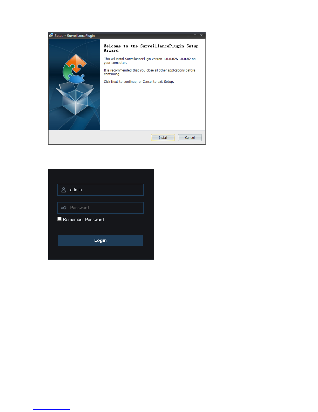
USER MANUAL
3.
After installing the plug-in, clo se & launch again your browser and repeat step 1 to open the
login page. Input your use r nam e and password to login the web client.
Note
: If you use Google Chrome, please use Ver sion V41 or below. If you use V42 to V44, you
need to enable NPAPI plugins. Please enter chrome://flags/#enable-npapi on URL bar to find and
enable NPAPI. It doesn’t support V45 or above so far.
87

USER MANUAL
For Mac Safari:
1.
Launch the Safari in your Mac, and ent er t he NVR IP address or DDNS domain name (Host
Name) you have set on NVR in the URL box.
2.
Download the plug-in "SurveillanceClient.dmg", locate the downloaded file and do uble click it.
3.
Click on "Continue" --> "Install". E nter user name and password for M ac computer,
Click on "Install Software" --> "Close" to finish installation.
4.
Close Safari and open again to r epeat st ep 1 to open the Web Clie nt log in page.
1
2
3
4
88

USER MANUAL
7.3 Web Client Manager
The web client supports to fully control the NVR with adm inistrator account. Please make sure to
protect your user name & passwor d for preventing illegal login.
7.3.1 Live Interface
This is the first screen th at opens a fter you hav e logged i n to the Web Client. Here y ou can open o r
close live preview, record video to local computer manually, take snapshots of the screens, PTZ
control, color adjustment, et c.
1- Channel List:
Open the channel list for quick camera function
Click button to display the Channel List.
Click button to hide the Channel List.
Turn the Live video stream on/off. The button is in blue color i f the liv e video stream is
on.
Manual Recording buttons. Click to start manually recording live stream video. Click
again to stop recording. Manua l rec ordings are saved to your comp uter. While in
recording, the button is in blue color.
Manual
snapshot
button. Click to save a snapshot of the current live display to your
computer.
Bitrate button. Set camera to use mainstream, subst r eam or mobile stream video
settings. Mobile stream is available for IP channels only.
89

USER MANUAL
2- Live Video Stre am Options:
Mainstream:
View all live videos using high-quality mainstream video settings.
Substream:
View all live videos using middle-quality substream video settings.
Mobile Stream:
View all live video using lower-quality mobile stream video settings to
conserve bandwidth. Available for IP channels only.
3- Main Menus:
Live:
View live video fro m cam er as.
Playback:
View recorded video which is saved in NVR’s HDD.
Remote Setting:
Access functions of the NVR setting menus.
Local Settings :
Set download locations for r ecordings and s napshot s taken using Web Client,
and choose file type for video fil es.
4- Information:
Hover over to see system details.
5- Exit.
6- Color Controls. Click to display or hide the color controls.
7-
PTZ Controls:
Click to display or hide the PTZ controls for using PTZ cameras.
8-
PTZ Controls
Directiona l Arrows: Cli
ck to move the PTZ camera
Automatic line scan.
PTZ Speed: Click to set th e speed of the PTZ camera’ s movement.
Zoom: Click –/+ to zoom in or out.
Focus:
Click –/+ to adjust focus.
Iris: Click –/+ to adjust iris.
Preset Point: Add, remove, or go to preset point.
Cruise:
Start/stop PTZ cruise
90

USER MANUAL
9- Live View Contr ol Buttons:
Open the images on Live window.
Close all the Live channels
Original Proportions: Shows live video at the origin al proportions
Stretch: Stretch live video to fit the full area for each channel on screen.
To enlarg e t he w eb c l ie nt to full screen.
Manual Recording: Click to st ar t manu ally recording for all display ed c hannels. Click
again to stop recording. Manua l rec ordings are saved to your comp uter.
Snapshot: Click to save snapshots of all current di splayed channels to your computer.
Digital Zoom: Click upon on a live im age, then click-and-drag ov er an ar ea of the live
image to enlarge. Right-click to r et ur n t o t he normal display.
Volume Control. Volume is mute.
10- Navigation:
Shows current page number f or t he channels shown on screen. Use t he ar r ow
keys to switch between pa ges.
11- Page View: Click to select how many channels appear on screen at a t ime.
7.3.2 Playback
You can search & play recording videos stored in the HDD ins ide t he NVR, and download the
videos to your computer.
91

USER MANUAL
To search recordings:
1. Click Playback in the top-right corner of the w i ndow.
2. Select a day on the calendar t o sear ch for recordings from. Days w ith r ecor dings appear with
a red underline.
3. Select the recording type to search for from the dropdow n next t o Type, or select All to
search for all recordings.
4. To choose the video stream you want to search & pl ay. If you want to play Substream
recordings, please make sure you had set the NVR to recor d w it h Dualstream at
5.2.2.1
Record.
5. Check the channels you would like to search for recordin gs from. Check Synchronous
playback to play all channels at once.
6. Click Search.
7. Recordings that fit your sear ch will be d isplay ed in th e timelin e. Clic k a section of video wher e
you would like to begin playback and click the play button.
7.3.2.1 Playback Control Buttons
Play the recordings
Pause
Stop
Go Forward One Frame:
Move frame-by-frame through playback. Only available when t he
Synchronous playback
option is not checked.
92

USER MANUAL
Click upon one of the channels w hich is being played and then clic k record button to record
current video to your comput er. Click again to stop recording.
Click upon one of the channels w hich is being played and then click capture button to take a
snapshot and save to your com put er.
Opens the Download menu, which allows you to download several video recordings at once.
Choose the files you want t o dow nload, press
Start Download
button to begin, you will see the
download status. Press
Stop Download
button to stop.
Playback Speed.
Click to choose the playing speed.
Play All Channels:
Click to play all channels y ou have chosen to searched. O nly available
when the
Synchronous p lay bac k
option is not checked.
Stop All Channels:
Click to stop playing all channels. Only available when the
Synchronous pla yback
option is not checked.
Digital Zoom: Click upon on a playing video, then click-and-drag over an area of the video to
enlarge. Right-click to return to the normal display.
Original Proportions: Shows the playing video at t he or ig inal proportions
Stretch: Stretch the playing video to fit the full area for each channel on screen.
To enlarg e t he w eb c l ie nt to full screen.
93

USER MANUAL
7.3.3 Remote Setting
Here you can remotely conf igure t he settings of the NVR. Plea se see “
Chapter 5 NVR System
Setup
” for more details on the NVR settings..
7.3.4 Local Setting
Set download locations for r ecordings and snaps hots taken using Web Client, and choose file type
for video files.
Record Path:
Click t o browse for a nd select the f older where y ou would like t he manual v ideo
recordings to be saved on your computer.
Download Path:
Click to browse for and select the folder where you would li ke to save the
download video recordings to your computer.
Snapshot Path:
Click to browse for and select the folder wher e you would like the manual
capture snapshots to be s aved on your computer.
File Type:
Choose your preferred file type for manual recordings.
Save:
Click to save the modifi cat ions.
94

USER MANUAL
Chapter 8 Viewing Backed Up Video on
PC/Mac
This section will help you to play the backup files with the pow er f ul v ideo player which is attached
in the CD.
For Mac users, please install the app “VideoPlayer_x.x.xx_xxxx_xx_x.dmg”, fo r example:
VideoPlayer_1.0.15_2017_01_6.dmg.
For PC users, please install the software “VideoP layer_x.x.xx_xxxx_xx _xx. exe”, for example:
VideoPlayer_1.0.15_2017_01_06.exe.
Minimum Syst em Requirements
• Intel Pentium 4 or above
• Microsoft Windows XP / Vista / 7 / 8 / 10
• 256MB RAM
• 16MB video memory
1. Install the Video Player software in the CD and run.
2. Copy the backup files to your computer.
3. Click Open File button or click
+ button on the Play List to load single or multiple video fil es. It
supports to add & play “.rf”, “ . avi”, “ .mp4”, “.264” and “.265” files. Click button to load a
folder with backed-up videos.
95
 Loading...