

Page 1
PRO
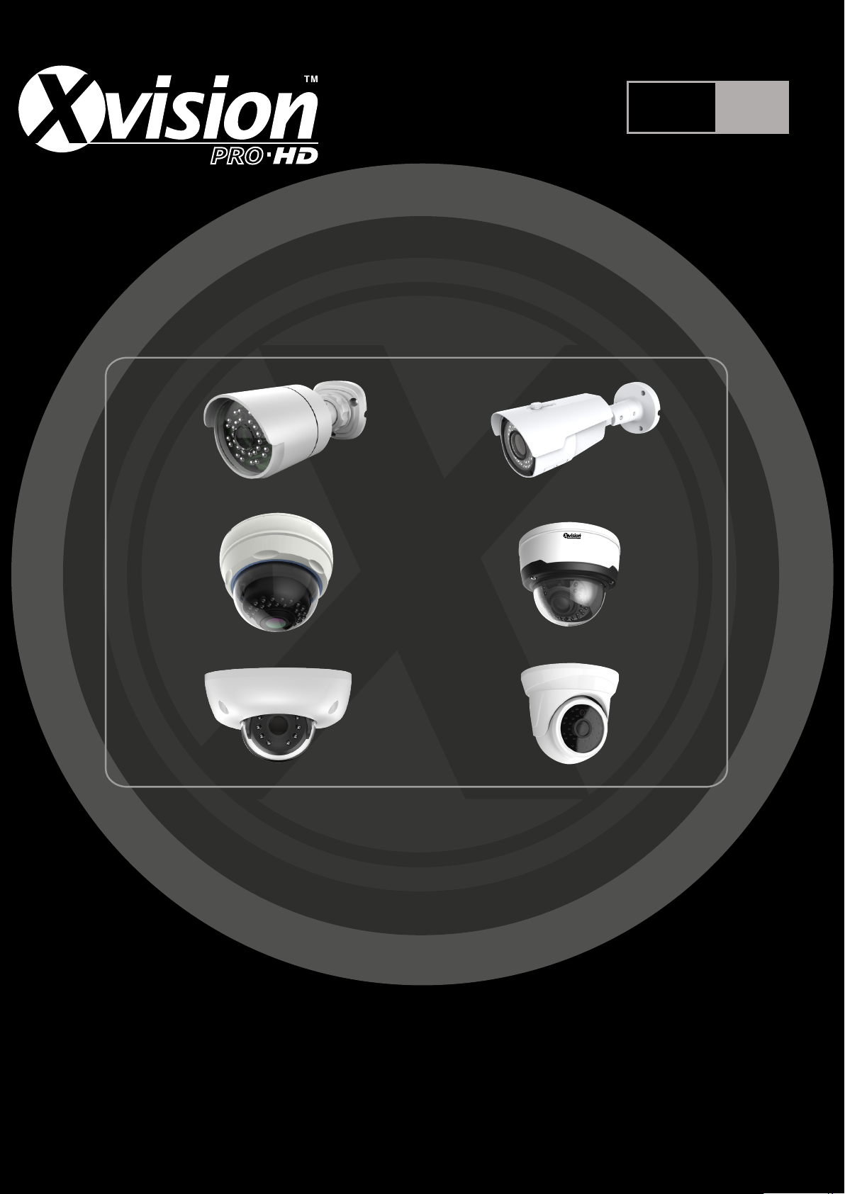
Professional HD IP Camera
XHD
HD
IP
User Guide
Thank you purchasing the X2C4000 HD IP Camera from Xvision Pro HD.
Please ensure that you read and understand this User Guide before operating the camera.
Please store this User Guide in an easily accessible location.
Version 1
Page 2
X2C4000 IPC Manual
Table of Contents
Table of Contents ................................................................................................................................................ 1
Functional Descriptions and Features ............................................................................................................. 3
SAFETY INSTRUCTION ................................................................................................................................... 1
Introduction .......................................................................................................................................................... 2
Pre-requisites ...................................................................................................................................................... 2
IPC Description and Device Connection ......................................................................................................... 3
Appearance Description................................................................................................................................. 3
Device Connection ........................................................................................................................................ 10
Device Search Tool .......................................................................................................................................... 11
Active X Setup ................................................................................................................................................... 14
Web Browser Interface..................................................................................................................................... 16
Live View ........................................................................................................................................................ 16
Remote Setting .............................................................................................................................................. 18
Display ............................................................................................................................................................ 18
Live .............................................................................................................................................................. 18
Image Control ............................................................................................................................................ 19
Privacy Zone .............................................................................................................................................. 20
ROI .............................................................................................................................................................. 21
Record ............................................................................................................................................................ 22
Rec Parameters ........................................................................................................................................ 22
Schedule .................................................................................................................................................... 23
Network .......................................................................................................................................................... 24
Network Setting ......................................................................................................................................... 24
Video Streaming ........................................................................................................................................ 25
Email ........................................................................................................................................................... 26
DDNS .......................................................................................................................................................... 27
IP Filter ....................................................................................................................................................... 28
RTSP .......................................................................................................................................................... 29
FTP .............................................................................................................................................................. 30
Alarm ............................................................................................................................................................... 31
Motion ......................................................................................................................................................... 31
Alarm ........................................................................................................................................................... 32
Lens Shade ................................................................................................................................................ 33
Device ............................................................................................................................................................. 34
SD Card ...................................................................................................................................................... 34
Log .............................................................................................................................................................. 35
Audio ........................................................................................................................................................... 36
Page 3
X2C4000 IPC Manual
System ............................................................................................................................................................ 37
Date/Time ................................................................................................................................................... 37
Users ........................................................................................................................................................... 38
Info .............................................................................................................................................................. 39
Advanced ....................................................................................................................................................... 40
Firmware Update....................................................................................................................................... 40
Load Default .............................................................................................................................................. 41
Maintain ...................................................................................................................................................... 42
PEA (Perimeter Alarm) .......................................................................................................................... 43
OSC –Object Care .................................................................................................................................... 46
X2C4000 Specification’s .................................................................................................................................. 49
FAQ ..................................................................................................................................................................... 55
Page 4
X2C4000 IPC Manual
Features
Brief Description
Real time
monitoring
Optimized H.265/H.264/MJPEG video compression algorithms; Multistream transmission ensures high definition image transmission on both
narrowband and wideband.
Recording
Support simultaneous connection of up to 5 video streams.
Onvif
Support ONVIF protocol, please check with www.xvision.com for latest
supported version.
Network
protocols
Support multiple network protocols, such as TCP/UDP
,IP,HTTP,DHCP,RTP,RTSP,FTP,SMTP,DNS,DDNS,NTP,ICMP,IGMP
,ARP, GB28181
Record backup
Backup via Browser and some IPC support MSD card.
POE
POE Power over Ethernet support on all IPC - 12 VDC ± 10%, PoE
Network
operation
Authorized accessing of remote client to ensure the system security.
APP Support
Smart phone video monitoring XIQCMS
Operating
Temperature/IP
Rating
-10 °C ~ 60 °C(14 °F ~ 140 °F – IP66 - below 90%RH
Functional Descriptions and Features
Note:
• IPC refers to Internet Protocol Camera.
• Default IP address of IP Camera:192.168.1.168
• IP Camera default Username: admin (lower case), Password:
admin (lower case)
• Default web port:80,Default media port:9988
• LAN refers to Local Area Network (Inside your router)
• WAN refers to Wide Area Network (outside your
Router/Home/Office)
Page 5

SAFETY INSTRUCTION
Do not install the equipment in an environment with too much
moisture, dust or smoke dust as this may result in fire or electric
shock.
In the unlikely event that the equipment should malfunction and emit
an abnormal smell of smoke, please immediately stop it, shut off the
power and contact your supplier.
Please do not place this equipment near a heat source to avoid risk of
fire.
Please do not store, install and use this product in danger areas with
inflammable or explosive substances.
Please make sure the power is turned off when installing the product.
Please do not use the IPC in an environment where temperatures that
exceed either -20°C to +55°C.
1
Page 6
Introduction
This guide is for the Xvision Pro HD X2C4000 Range of IP Cameras.
It is recommended that the units are setup and tested before being mounted or installed.
These instructions are for guidance only detailed information is in accordance with the
product.
The instructions may include some technical inaccuracies or typographical errors, these
will be corrected in future updates.
The product or procedures described in the instructions may be changed or updated at
any time without prior notice. Screenshots used in the instruction are only for indications
and explanations.
Screenshots used in the instruction are only for indications and explanations.
This Manual will cover the following:
• Schematic Diagram of XC Cameras
• Basic setting setup
• Setting an IP address
• Active X Controls
• Viewing on IE
• Specifications
Pre-requisites
Note before you begin installation:
• Connect only one X2C400 range IPC at a time to your LAN, as all
cameras share the same default IP 192.168.1.168
• Screw Drivers
• Router/Switch/Hub for your LAN, this is needed to connect all Network IP
equipment together.
• A Windows PC/Laptop on site connected to the same LAN
(Router/Switch) as your equipment.
• Cat 5 Patch cables to connect your X2C4000 and Router/Switch all
together
2
Page 7
Items
Descriptions
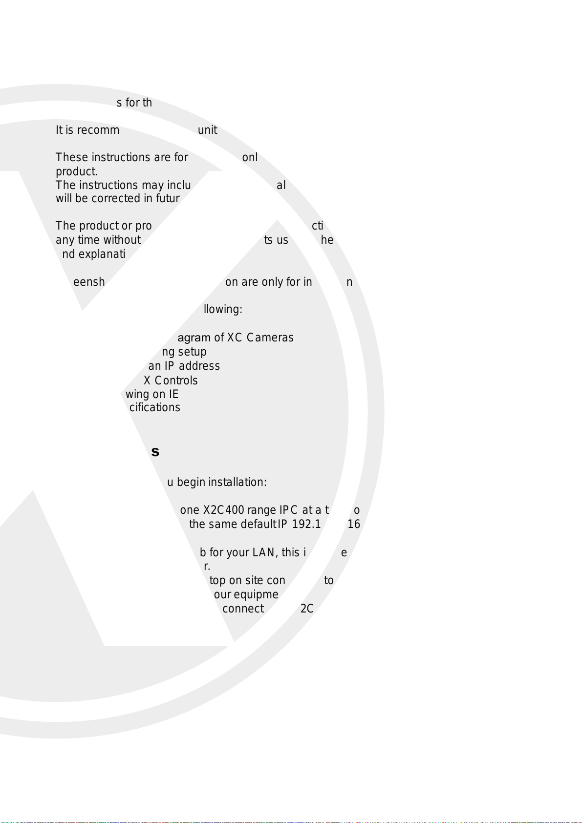
①Front cover
Helps protect the IPC from sunlight and rain.
②Rear cover
Fixed with the front cover.
③Set screw
Secure the front cover and rear cover.
④Lens
Lens of IPC
⑤Infrared IR’s
Infrared IR’s behind glass cover
⑥Ball and sleeve
Rotatable, used to adjust the angle of view of the IPC.
⑦Locknut
Fix the ball sleeve and the base.
⑧Base
Base to be secured against wall.
⑨Fixing hole
Screw holes to secure IPC to wall.
IPC Description and Device Connection
Appearance Description
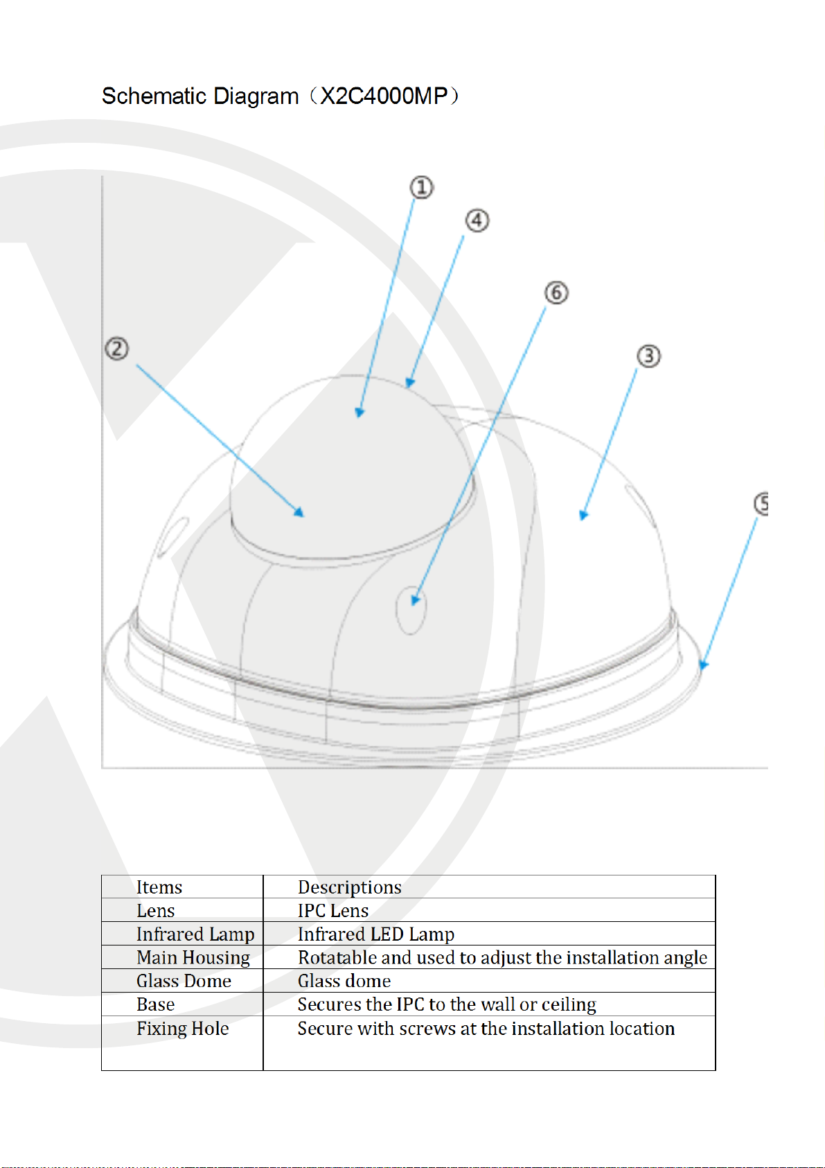
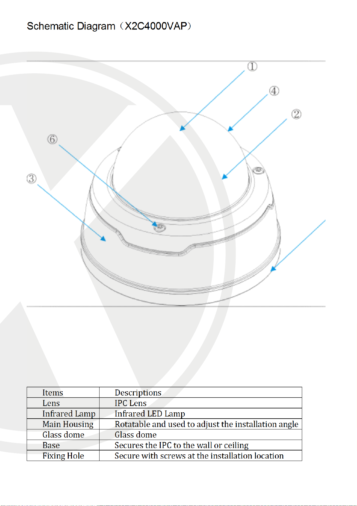
The X2C4000 cameras can be wall or ceiling mounted, so to install the camera you will need
to adjust it to the desired angle. Below you will see how to install each camera type
Schematic Diagram(X2C4000BP)
3
Page 8
Items
Descriptions
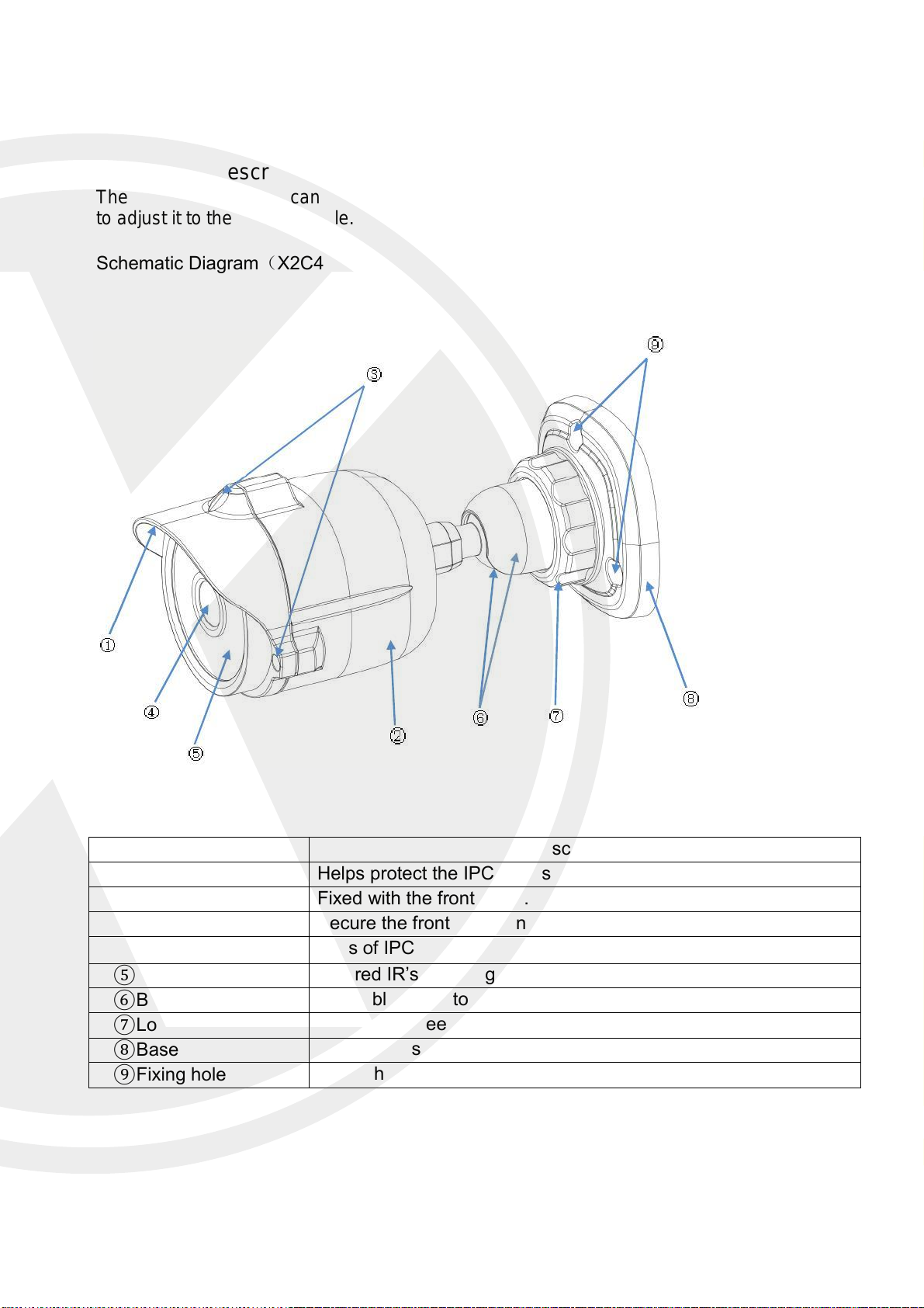
① Front cover
Helps protect the IPC from sunlight and rain.
② Rear cover
Fixed with the front cover.
③Focusing lever
Adjust the focal length of the IPC.
④Lens
Lens of IPC
⑤ Infrared IR’s
Infrared IR’s behind glass cover
⑥ Ball and sleeve
Rotatable, used to adjust the angle of view of the IPC.
⑦ Locknut
Fix the ball sleeve and the base.
⑧Base
Base to be secured against wall.
⑨ Fixing hole
Screw holes to secure IPC to wall.
Schematic Diagram(X2C4000BVP)
4
Page 9
Items
Descriptions
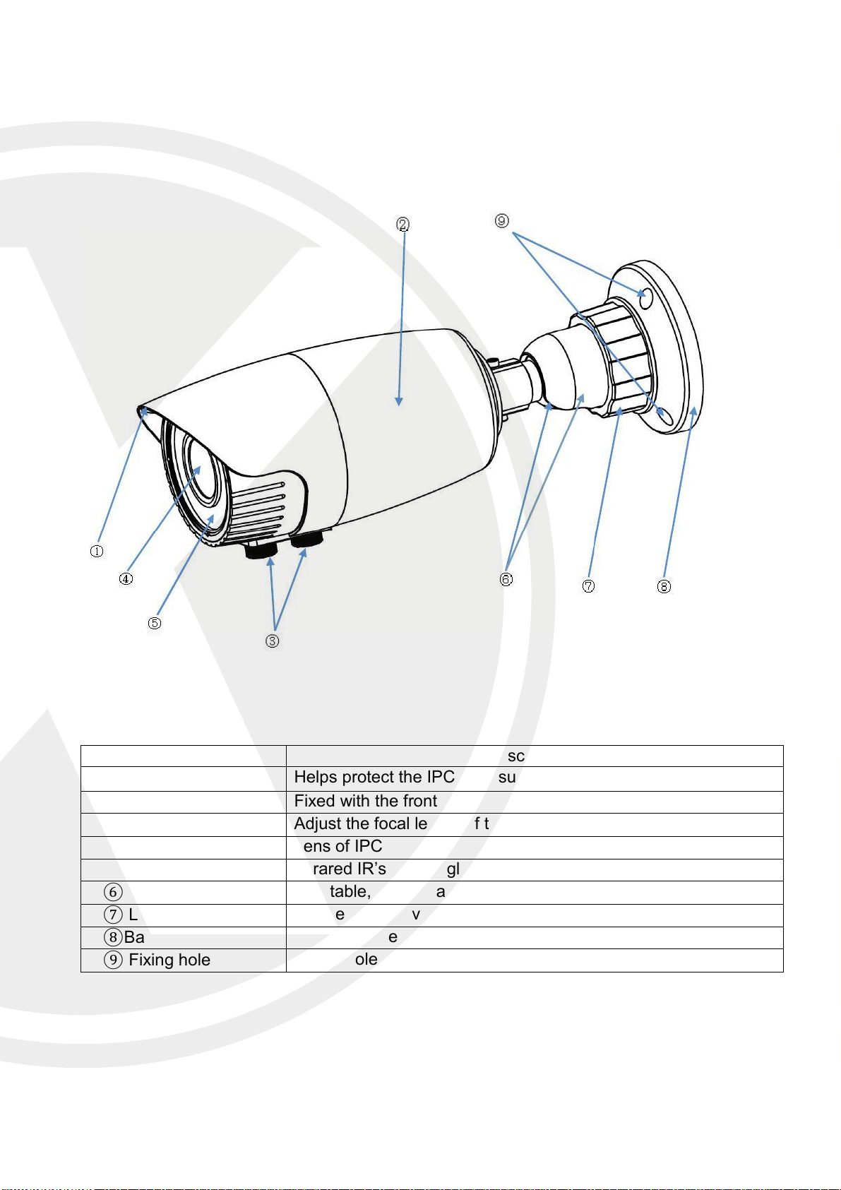
① Transparent cover
Protects the IPC lens and IR’s.
② Infrared IR’s
Infrared IR LED’s
③ Lens
Lens of IPC
④ Black inner cover
Hides IPC mechanics.
⑤ Adapter disc
This will connect to the additional bracket.
Schematic Diagram(X2C4000VAP)
① ② ③ ④
⑤
6
Page 10
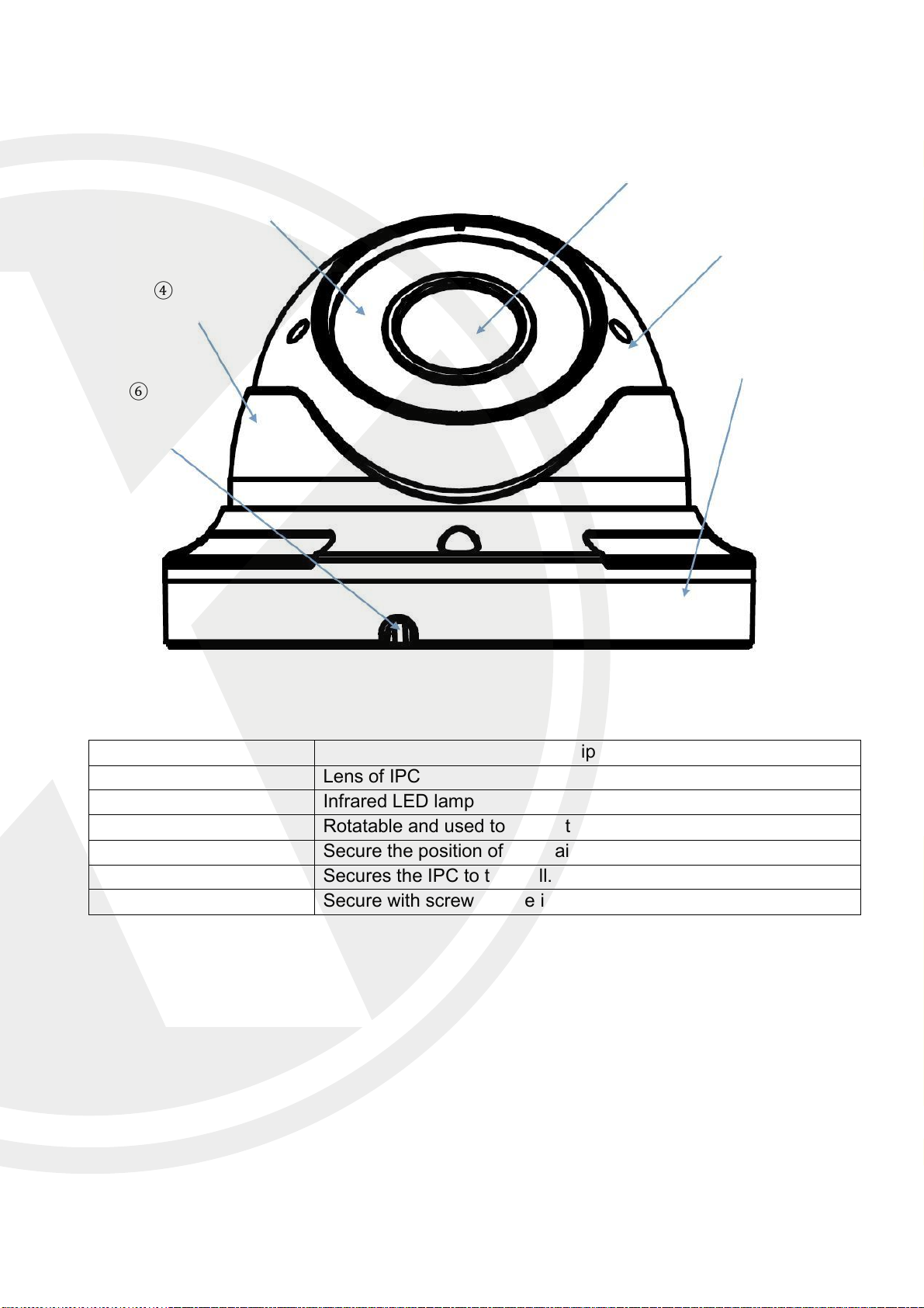
Items
Descriptions
① Lens
Lens of IPC
② Infrared lamp
Infrared LED lamp
③ Main housing
Rotatable and used to adjust the installation angle
④ Fixed guard
Secure the position of the Main housing.
⑤ Base
Secures the IPC to the wall.
⑥ Fixing hole
Secure with screws at the installation location.
Schematic Diagram(X2C4000VP)
② ③
④
⑥
①
⑤
7
Page 11
8
Page 12
9
Page 13
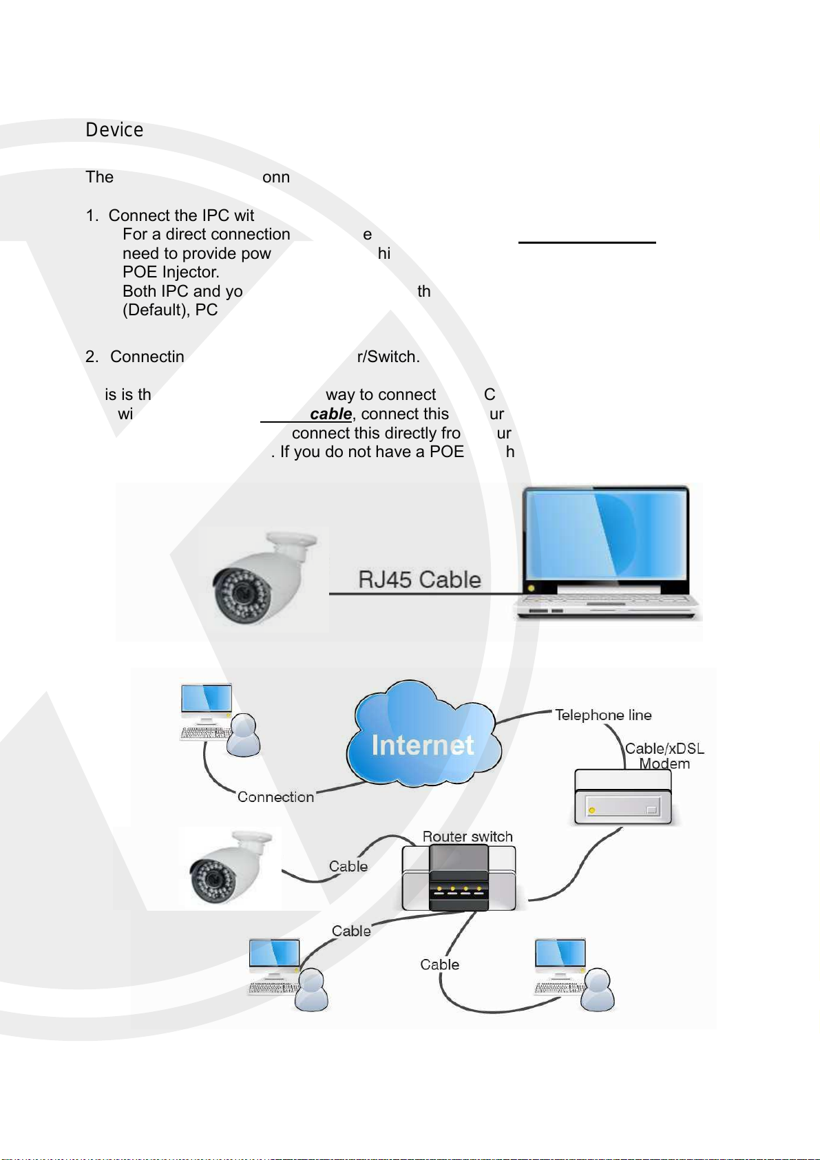
Device Connection
There are two types of connection method:
1. Connect the IPC with your PC.
For a direct connection you will need to use a CAT5/6 Cross over cable. You will still
need to provide power to the IPC, this can be done with a 12v Dc power supply or a
POE Injector.
Both IPC and your PC will need to be in the same IP subnet e.g. IPC 192.168.1.168
(Default), PC 192.168.1.100.
2. Connecting the IPC to your Router/Switch.
This is the most commonly used way to connect the IPC to your network.
You will need a CAT5/6 Patch cable, connect this to your IPC and your router/switch. If you
have a POE switch you can connect this directly from your IPC to your switch and the IPC
will receive power as well. If you do not have a POE switch you will need to provide power to
your IPC.
10
Page 14
Device Search Tool
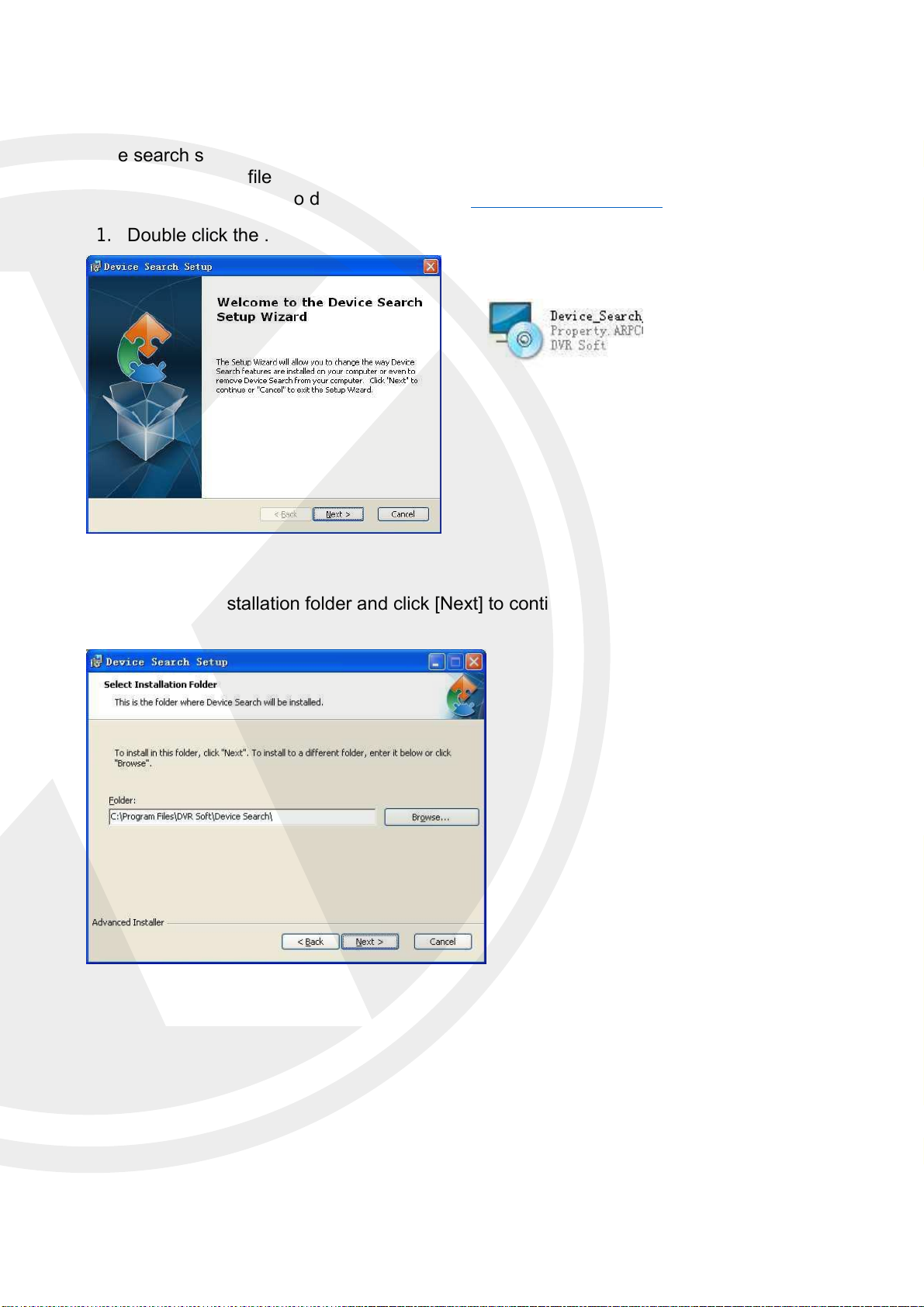
The search software will search your LAN, you can also use the XIQCMS to find your IPC.
Firstly, install .exe file (Device Search) found on the included CD by the following
procedures, you can also download this from http://www.Xvision.com.
1. Double click the .exe file
2. Click next to continue
3. Select installation folder and click [Next] to continue.
11
Page 15
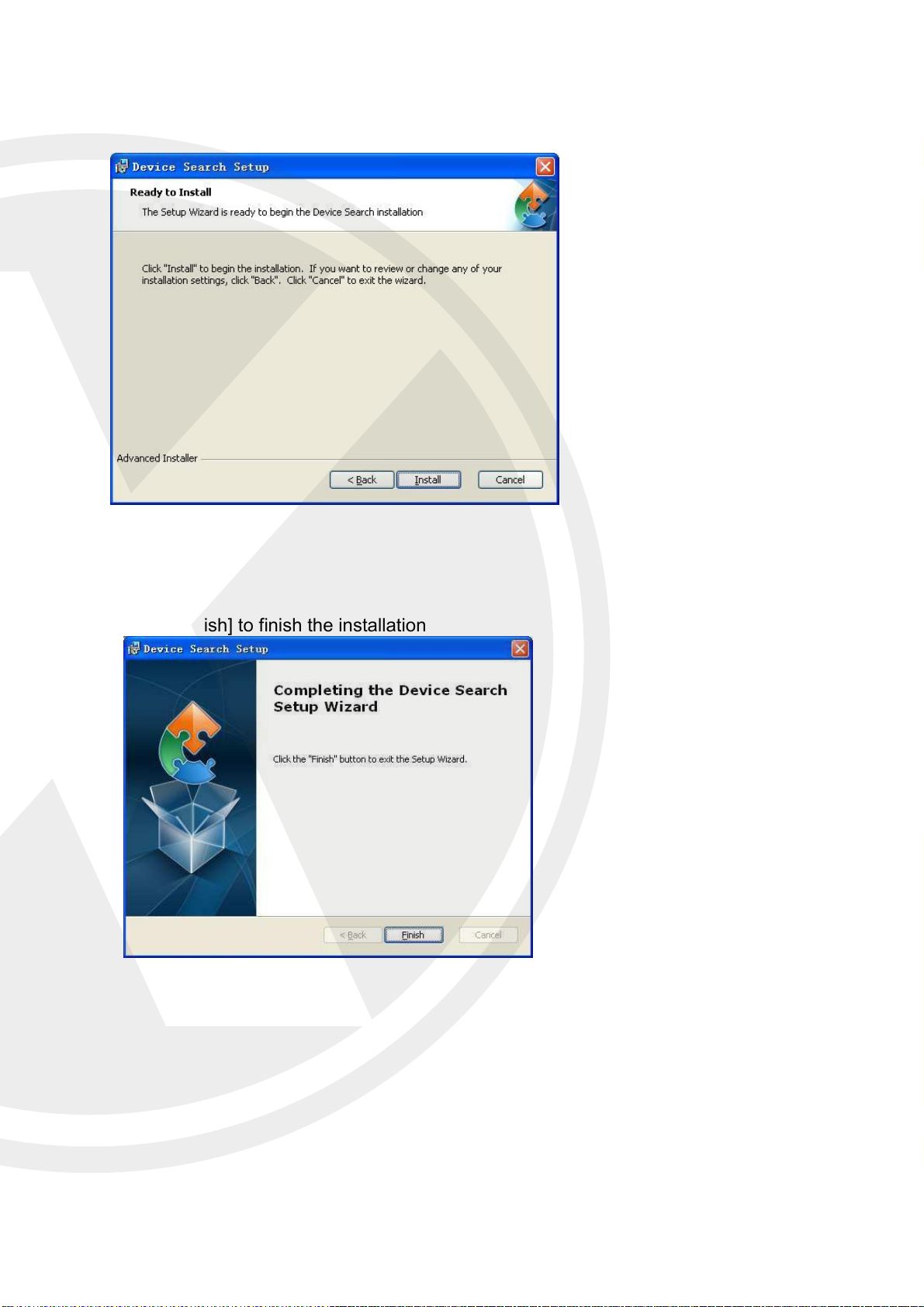
5. Click [Finish] to finish the installation
4. Click [Install] to begin the
installation.
12
Page 16
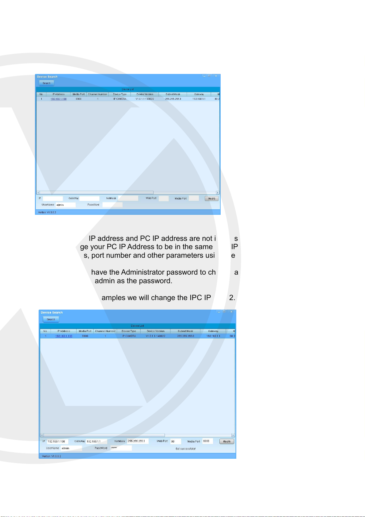
Once installed, run the Search tool. This will search your LAN for the IPC. Once found it will
bring back the IPC, IP Address, Subnet mask and MAC Address. As shown in the following
picture:
If the searched IP address and PC IP address are not in the same network segment, you will
have to change your PC IP Address to be in the same LAN IP range. You can change the IP,
IP, Subnet mas, port number and other parameters using the device search.
You will need to have the Administrator password to change any settings, Default is User
name admin and admin as the password.
For the following examples we will change the IPC IP to 192.168.1.100.
13
Page 17
Active X Setup
Before we can access our newly setup X2C4000 on IE there a few more steps.
Open Internet Explorer and type in your IPC IP address in the address bar and press
enter on the keyboard.
The correct way to type the address is http://192.168.1.100.
You will be prompted for Active X controls to be installed. For this to go
successfully we need to change your settings of your IE browser. To setup the
ActiveX Controls and Plug-ins, please follow the steps below.
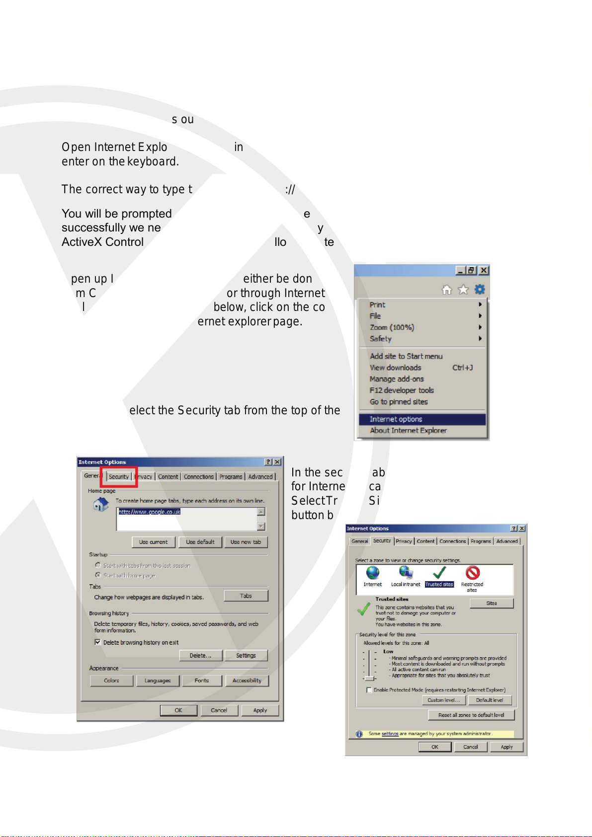
Open up Internet options, this can either be done
from Control Panel on your PC or through Internet
Explorers settings as shown below, click on the cog
on the top right of your Internet explorer page.
Once open select the Security tab from the top of the
page.
In the security tab you will be given the options
for Internet, Local Intranet and Trusted Sites.
Select Trusted Sites and then click on the Sites
button below.
14
Page 18
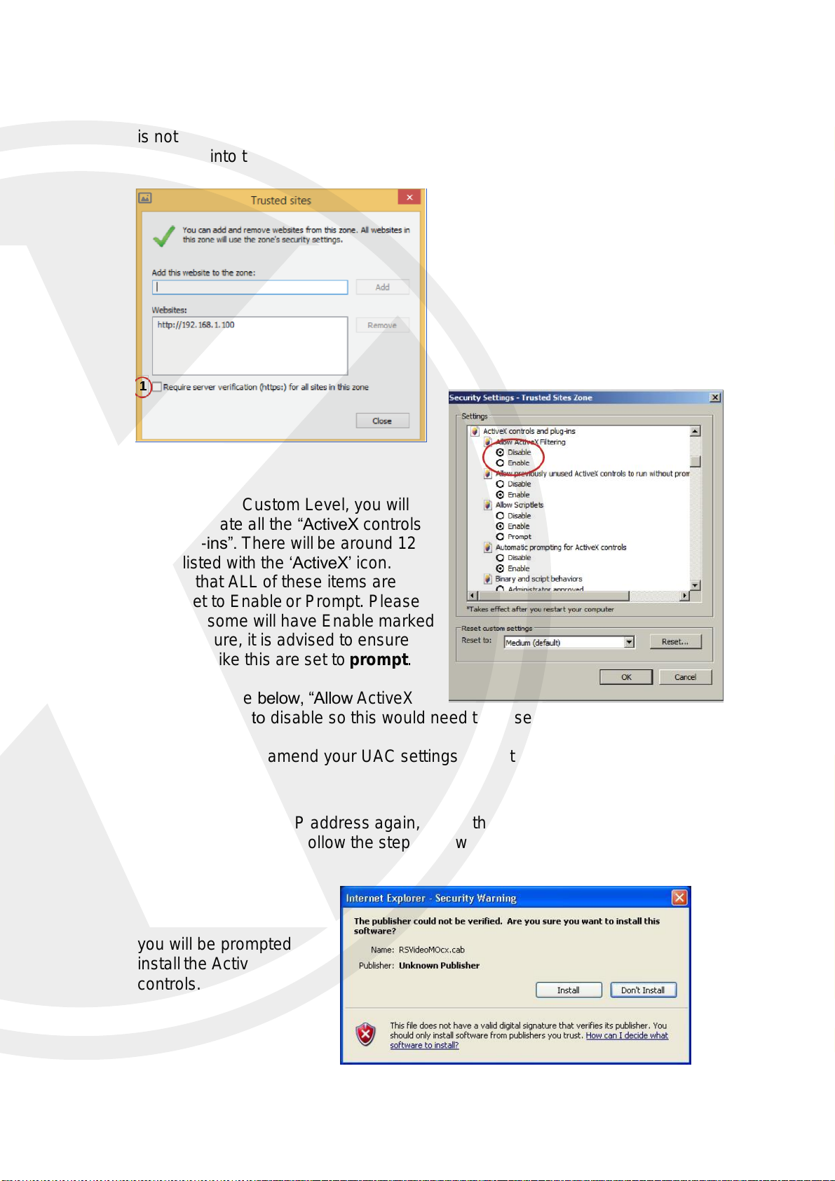
First, click on (1) “Require sever verification (https :) for all sites in this zone” so that it
is not ticked, as shown in the image. Then, you can type the IP address of your
X2C4000 into the text box at the top and then click Add.
Next, click on Custom Level, you will
need to locate all the “ActiveX controls
and plug-ins”. There will be around 12
items listed with the ‘ActiveX’ icon.
Ensure that ALL of these items are
either set to Enable or Prompt. Please
note that some will have Enable marked
as not secure, it is advised to ensure
that items like this are set to prompt.
As you can see below, “Allow ActiveX
Filtering” is set to disable so this would need to be set to enable.
You may need to amend your UAC settings, to do this please follow our
UAC guide.
Now you can try the IP address again, install the active X controls and view
your X2C4000 on IE. Follow the steps below to install this function.
17
Login to the X2C4000
through the browser.
Click on ‘allow’ and then
you will be prompted to
install the Active X
controls.
15
Page 19
Web Browser Interface
Live View
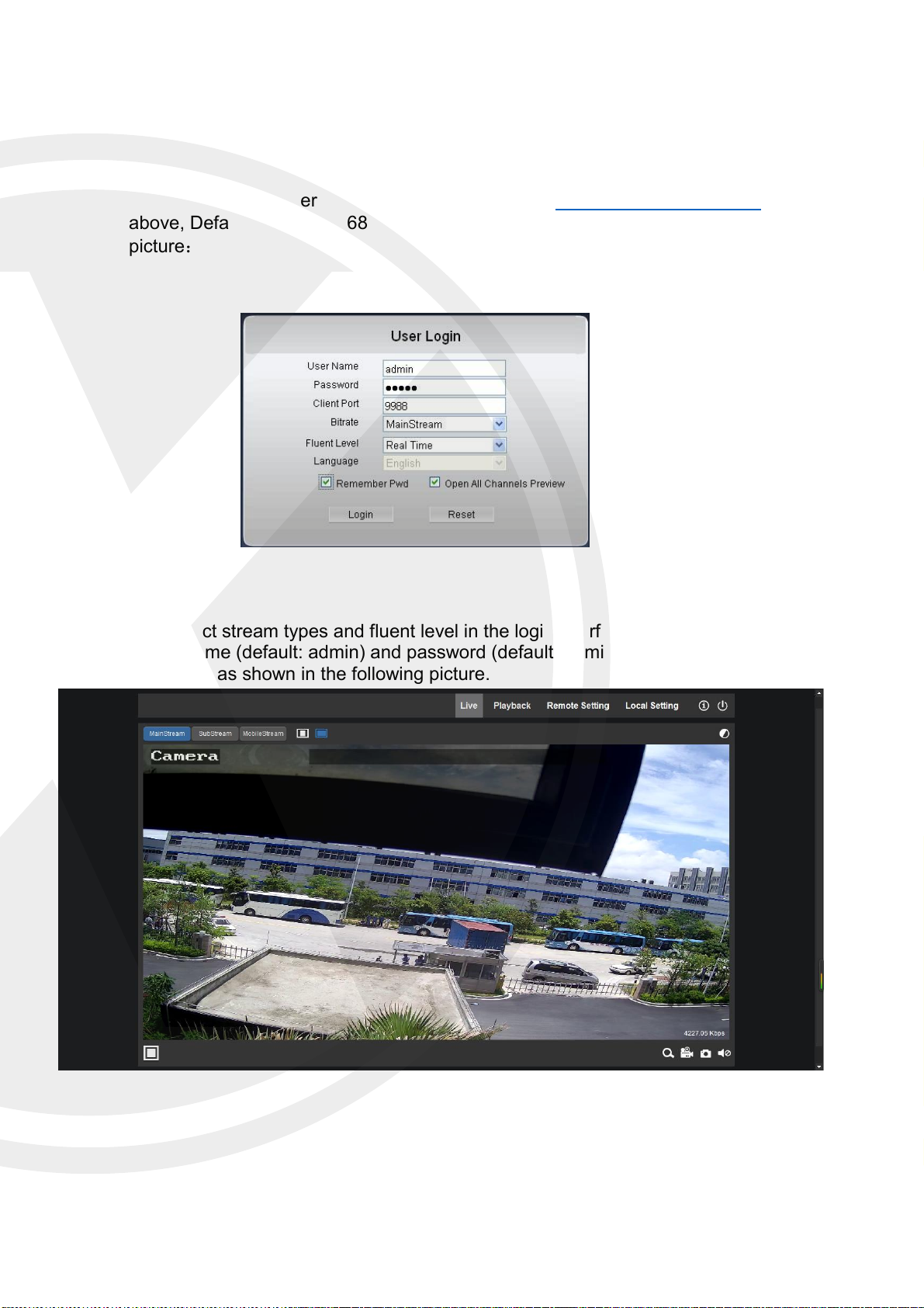
Open Internet Explorer and input IP address of IPC http://192.168.1.100 if set as
above, Default http://192.168.1.168. The login dialog box will appear. See the following
picture:
You can select stream types and fluent level in the login interface.
Input user name (default: admin) and password (default: admin) and click “Login” to enter the
Live interface, as shown in the following picture.
16
Page 20
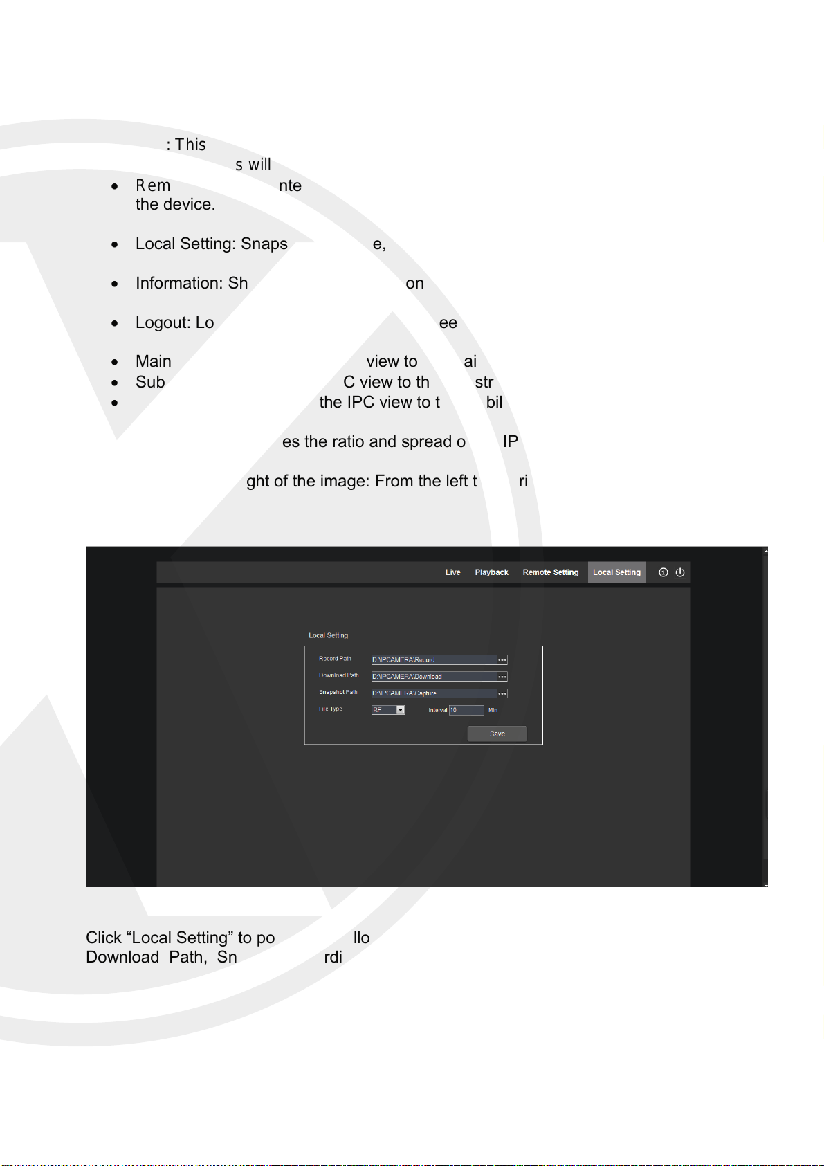
Other buttons on the Live interface:
Live: This shows the live image.
Playback: This will show the play back menu.
Remote Settings: Enter the device setting menu and set customized parameters of
the device.
Local Setting: Snapshot, file ty pe, storage path, etc.
Information: Shows the IPC information.
Logout: Logout and return to the login screen.
Main Stream: changes the IPC view to the main stream.
Sub Stream: changes the IPC view to the sub stream.
Mobile Stream: changes the IPC view to the Mobile stream.
Picture ratio: Changes the ratio and spread of the IPC image.
In the bottom right of the image: From the left to the right Zoom/ Record/ Snap shot
and Audio.
Click “Local Setting” to pop up the following dialog box, User can set Record Path,
Download Path, Snapshot recording.
17
Page 21
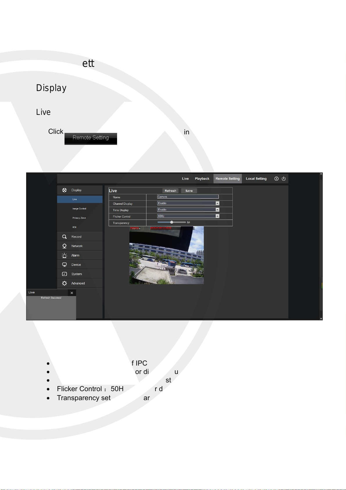
Remote Setting
Display
Live
Click
,and enter the following interface (Live interface by default)
Channel Name: Name of IPC
Channel Display: Enable or disable. Customize the display location.
Time Display Enable or disable. Customize the display location.
Flicker Control :50HZ, 60HZ or disable
Transparency set the transparency of OSD background color.
18
Page 22
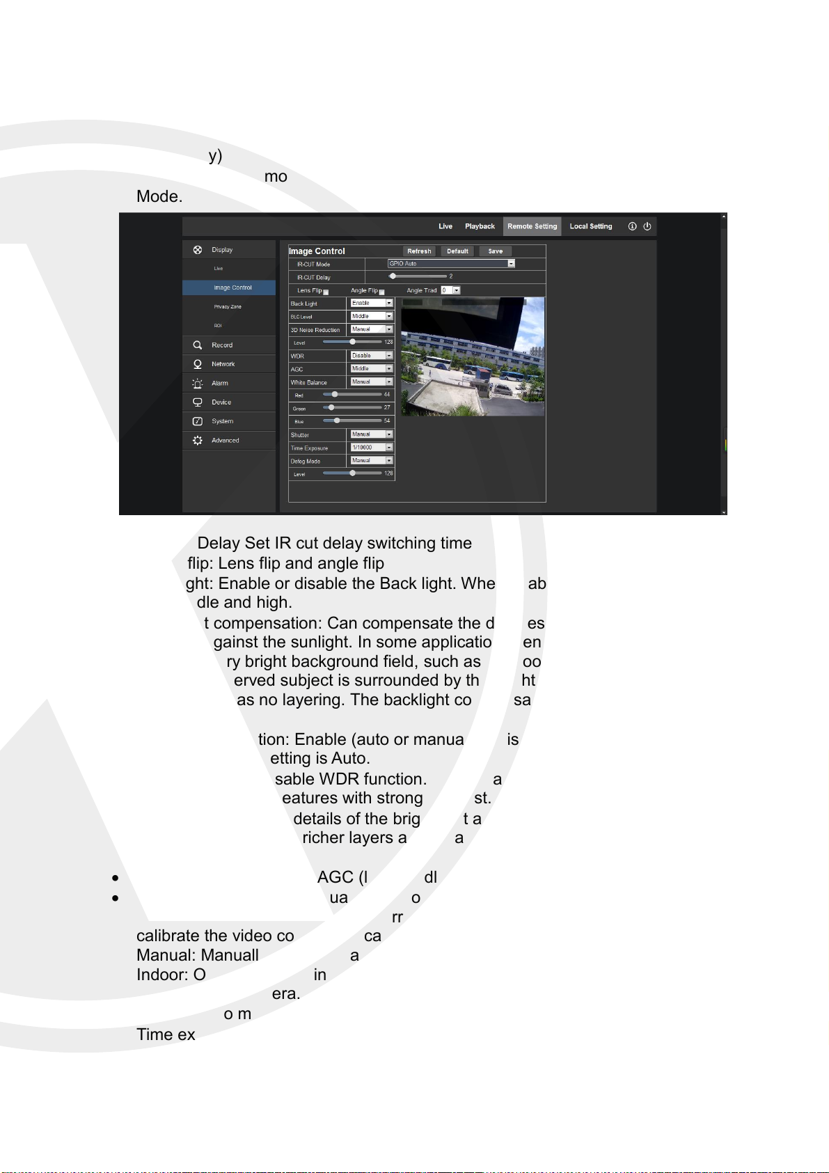
Image Control
Click (Display) → (Image Control) to enter the following interface.
IRCUT Mode:4 modes: GPIO Auto, Video Auto, Color Mode and Black & White
Mode.
IR-CUT Delay Set IR cut delay switching time
Image flip: Lens flip and angle flip
Back light: Enable or disable the Back light. When enabled, there are three levels:
low, middle and high.
Back light compensation: Can compensate the darkness of the subject caused by
shooting against the sunlight. In some application scenario, the field of view may
contain a very bright background field, such as the door and window against the light,
while the observed subject is surrounded by the bright field. In this case, the photo is
gloomy and has no layering. The backlight compensation can be applied to solve the
problem.
3D Noise Reduction: Enable (auto or manual) or disable the video noise reduction
function. Default setting is Auto.
WDR: Enable or disable WDR function. WDR is a technology that enables the camera
to catch the image features with strong contrast.
DR (Dynamic range) details of the bright part and dark part of image. The larger
dynamic range shows richer layers and broader color space.
AGC: Adjust the level of AGC (low, middle and high)
White Balance: Auto, manual and indoor
Auto: Optimize according to the current lighting conditions and screen mode and
calibrate the video color of the camera.
Manual: Manually adjust red and blue gain of camera video
Indoor: Optimize according to the indoor environment and automatically calibrate the
video color of camera.
Shutter: Auto mode and manual mode. Default mode is Auto.
Time exposure: Adjust exposure level of camera.
19
Page 23
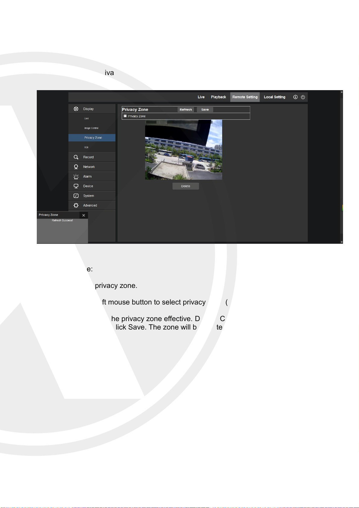
Privacy Zone
Click (Display)→ (Privacy Zone)
Set privacy zone:
1. Click to enable privacy zone.
2. Press and drag left mouse button to select privacy zone (4 zones at maximum).
3. Click Save to make the privacy zone effective. Delete: Click Refresh, select a privacy
zone, click Delete, and click Save. The zone will be deleted.
20
Page 24
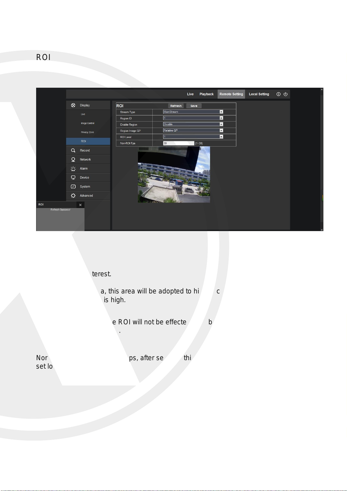
ROI
ROI is region of interest.
You can draw an area, this area will be adopted to high encode bit rate, when in preview and
record, the resolution is high.
Other areas not within the ROI will not be effected. The bit rate is lower, in this way, can
save space and bandwidth.
Normally the IPC bitrate is 30fps, after set ROI, this area is still 30fps, and other area can be
set lower.
21
Page 25
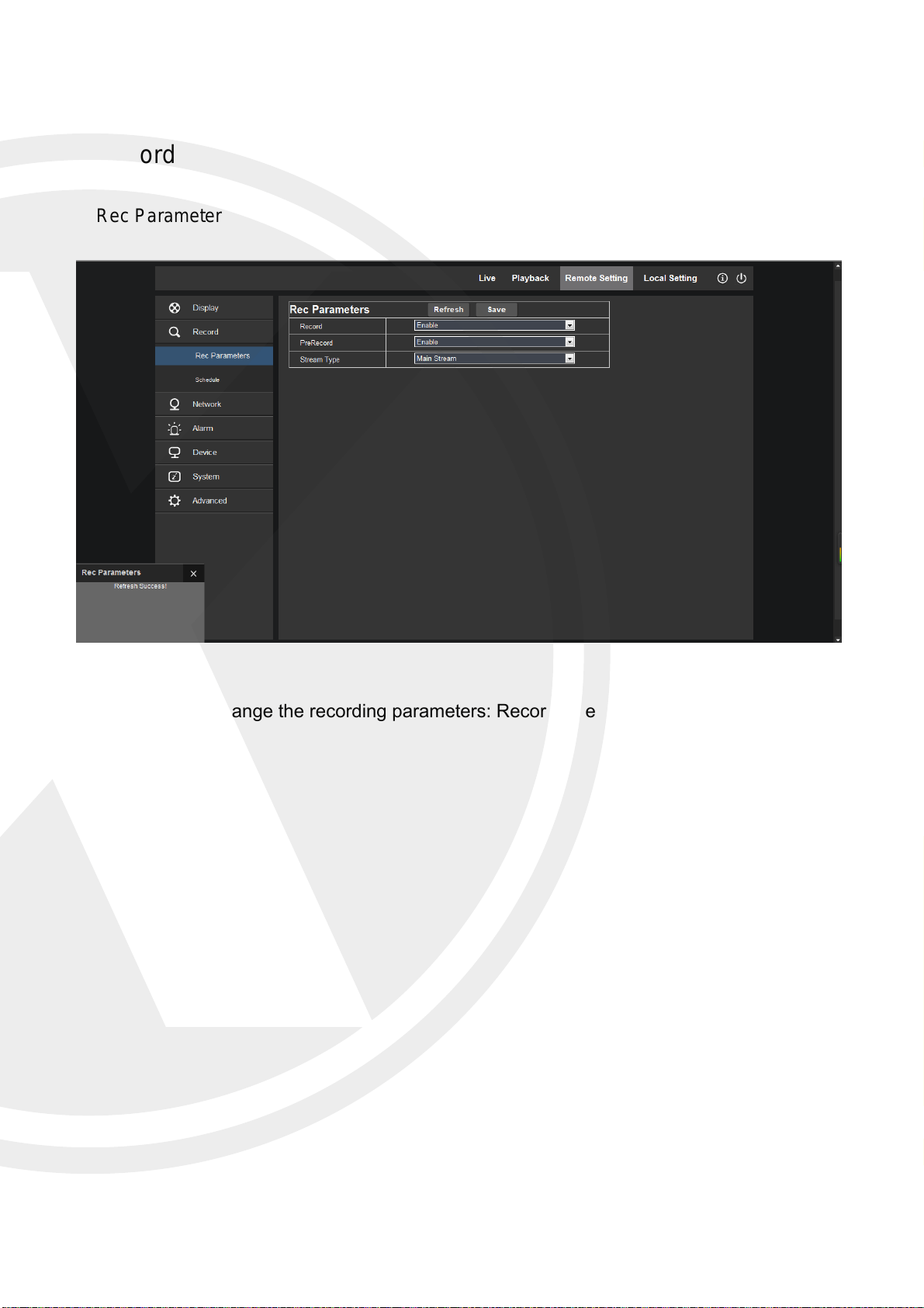
Record
Rec Parameters
Here you can change the recording parameters: Record, Pre Record and Stream type.
22
Page 26
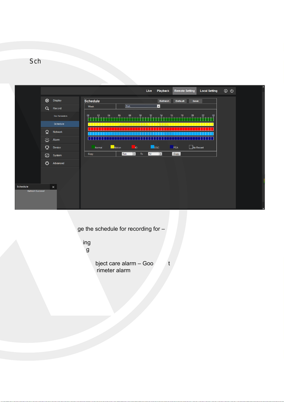
Schedule
Here you can change the schedule for recording for –
Normal recording
Motion recording
I/O recording
OSC recording – Object care alarm – Goods lost or left
PEA recording – Perimeter alarm
23
Page 27
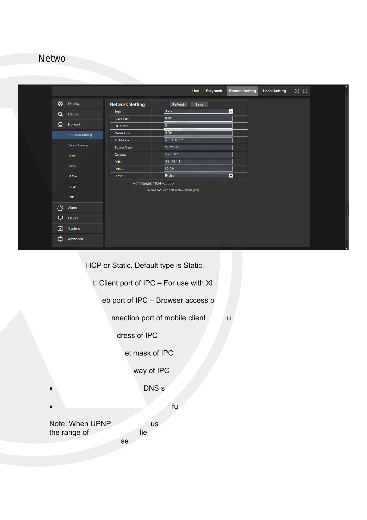
Network
Network Setting
Type: DHCP or Static. Default type is Static.
Client Port: Client port of IPC – For use with XIQCMS
Web Port: Web port of IPC – Browser access port
Mobile Port: Connection port of mobile client – For use with XIQ Mobile CMS
IP address: IP address of IPC
Subnet Mask: Subnet mask of IPC
Gateway: Default gateway of IPC
DNS1/DNS2:Configure DNS server
UPNP :Enable or disable UPNP function of device.
Note: When UPNP is enabled, user has to set the client port, web port and mobile port in
the range of 1024-65535. Client port is used for the connection of self-developed mobile
client; Mobile port is used for the connection of XIQ Mobile CMS.
24
Page 28
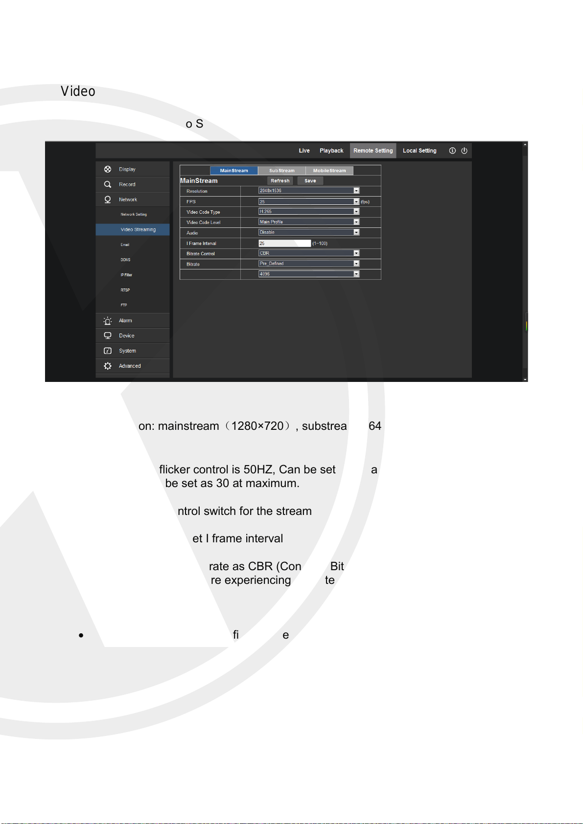
Video Streaming
Click (Network) → (Video Streaming)
Resolution: mainstream(1280×720), substream(640×480), mobilestream(
320×240)
FPS: When flicker control is 50HZ, Can be set as 25 at maximum; when flicker control
is 60HZ, can be set as 30 at maximum.
Audio: Audio control switch for the stream
I Frame Interval: Set I frame interval
Rate Control: Set the rate as CBR (Constant Bit Rate) or VBR (Variable Bit Rate),
these will help if you are experiencing pixelated image across your LAN/WAN on your
IPC.
Bit Control: Set bit rate as fixed value or pre-defined.
25
Page 29
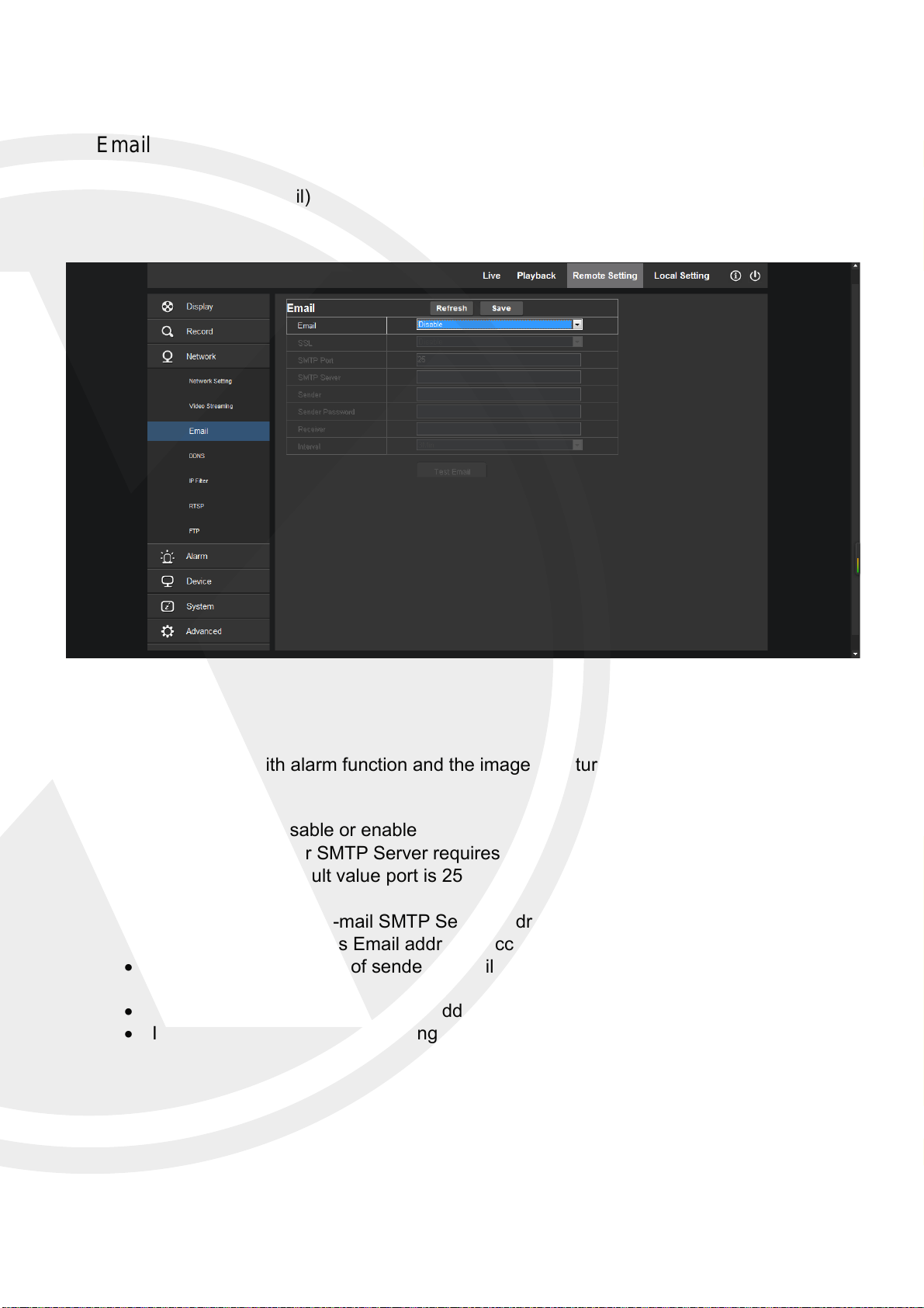
Email
Click (Network) → (Email)
Apply this function with alarm function and the images captured during alarming can be sent
to an email receiver.
Enable Email: Disable or enable
SSL: Enable if your SMTP Server requires SSL.
SMTP Port : Default value port is 25
SMTP Server: Input E-mail SMTP Server address
Sender Email: Sender’s Email address (Account for your IPC to send emails)
Sender Pwd: Password of sender’s Email (Email password for your IPC to send
emails)
Receiver Email: Receiver’s Email address (End user to receive emails)
Interval: Select interval for sending Emails (1min, 3min, 5min, 10min)
26
Page 30
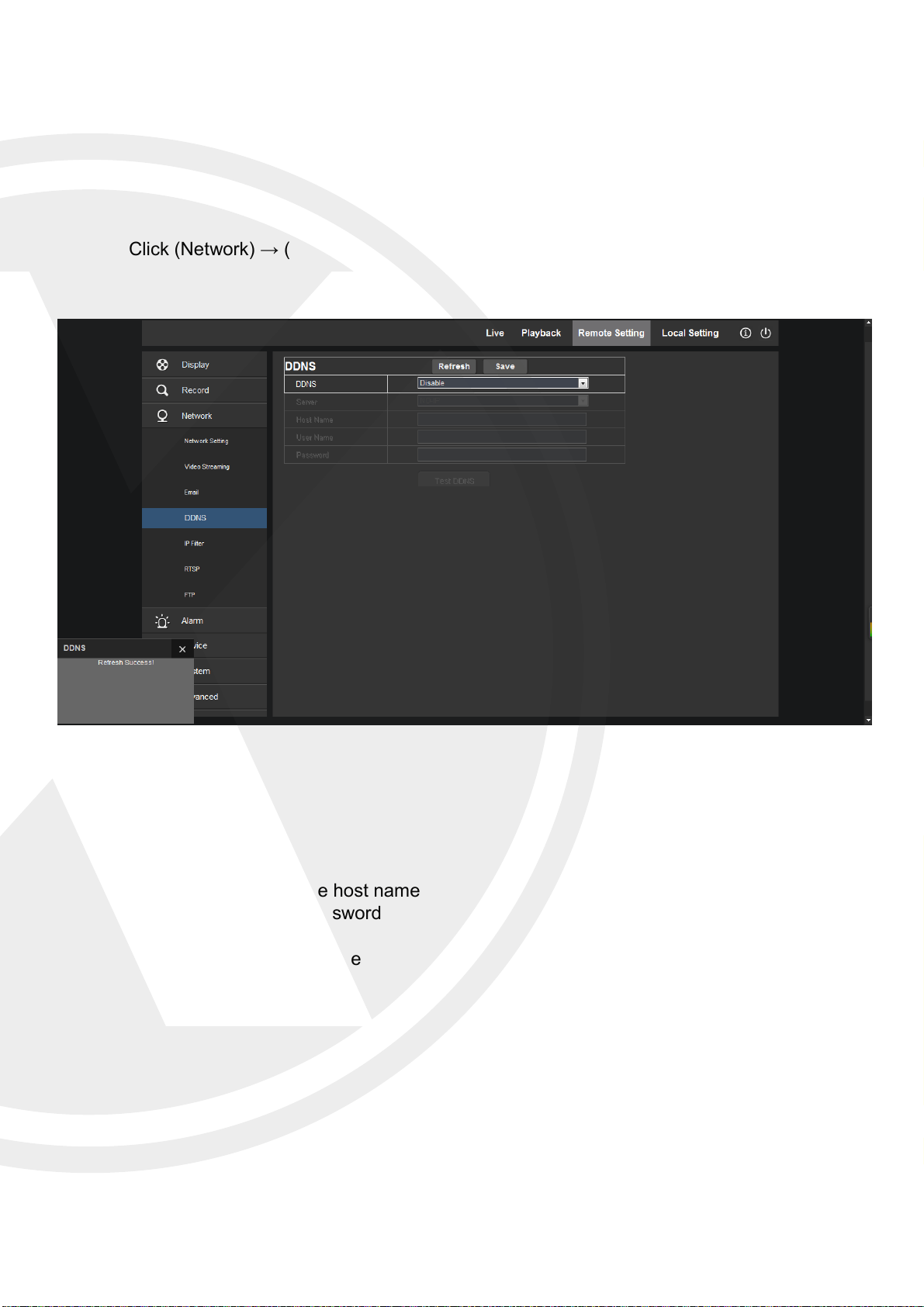
DDNS
Click (Network) → (DDNS)
DDNS: Enable
Host Name: Input the host name
Password: User’s password
Server: Select 3322
User Name: User’s name
27
Page 31
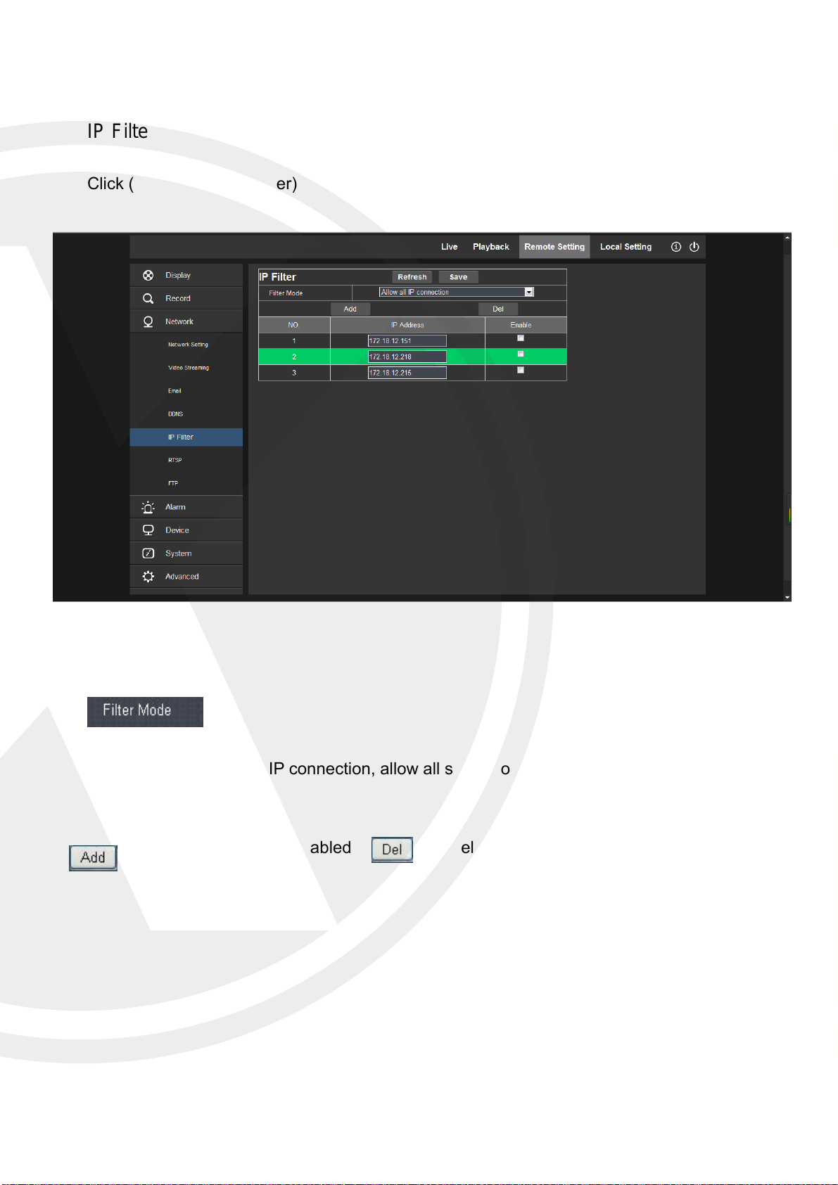
IP Filter
Click (Network) → (IP Filter)
IP connection:
Three modes:
:Add allowed IP or disabled
IP
allow all IP connection, allow all set IP connection, and disable set
:Delete added IP
28
Page 32
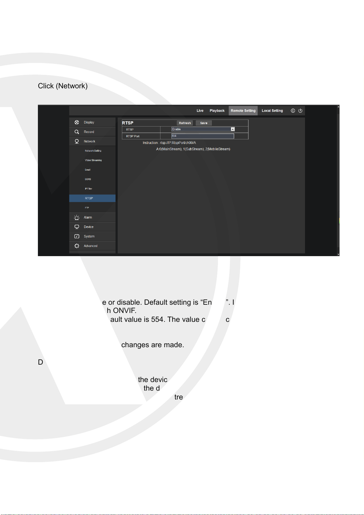
RTSP
Click (Network) → (RTSP)
RTSP: Enable or disable. Default setting is “Enable”. If it is set as “Disable”, user may
not find through ONVIF.
RTSP Port: Default value is 554. The value can be changed in the range of 1024-
65535.
The IPC will reboot if any changes are made.
Description:
o RTSP://IP:Port/A
o IP: IP address of the device
o Port: RTSP port of the device
o A: 0, 1, 2 - 0 refers to main stream,1 refers to sub stream, 2 refers to mobile
stream.
29
Page 33
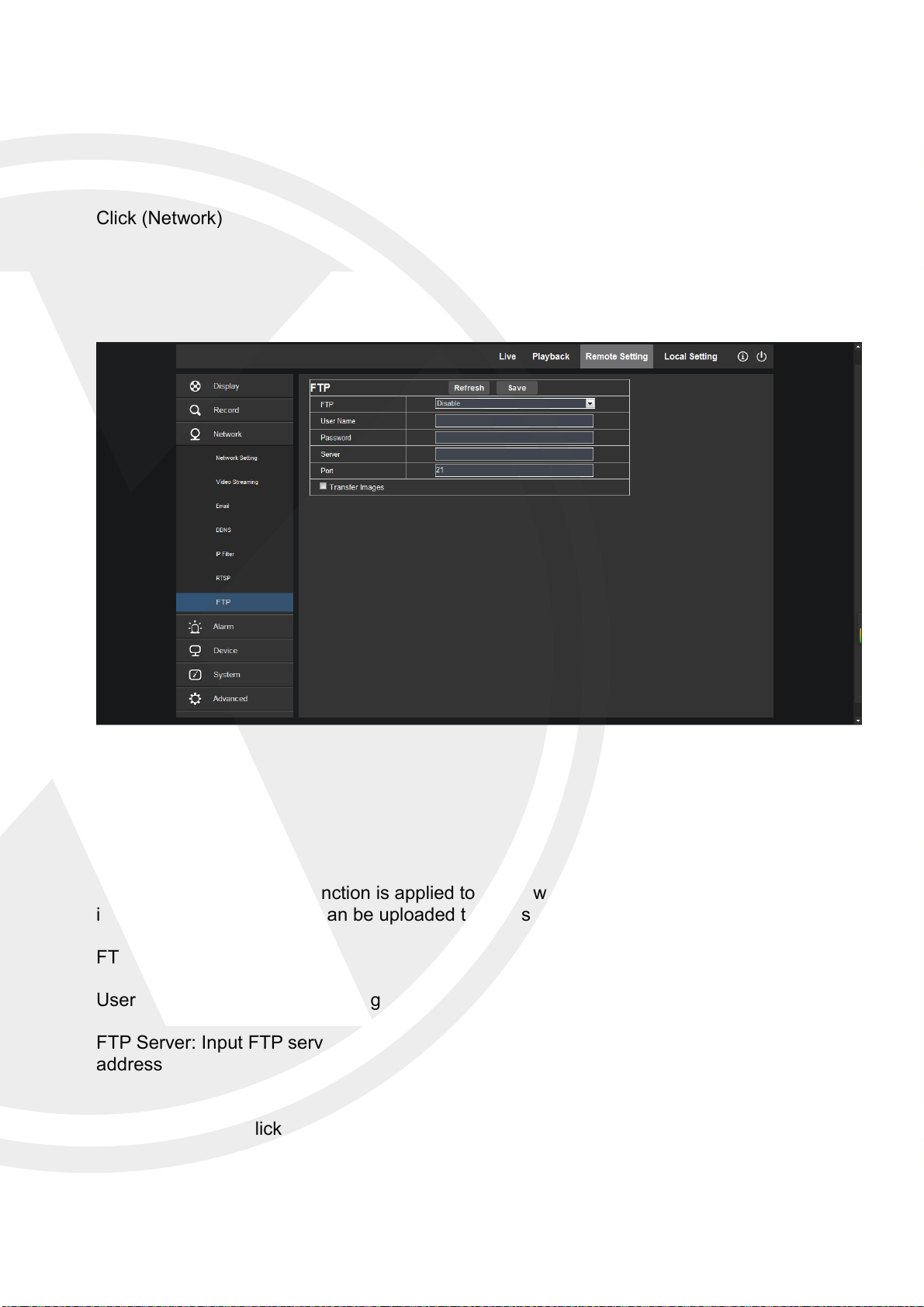
FTP
Click (Network) → (FTP)
FTP service setting. This function is applied together with alarm function. The captured
images or alarm recording can be uploaded to FTP server through network.
FTP: Enable or disable
User Name: User name for visiting FTP Password: Password for visiting FTP
FTP Server: Input FTP server
Port: FTP service port, default value is 21
address
Transfer Images: Click to transfer
Transfer Stream: Click to transfer stream
images
30
Page 34
Alarm
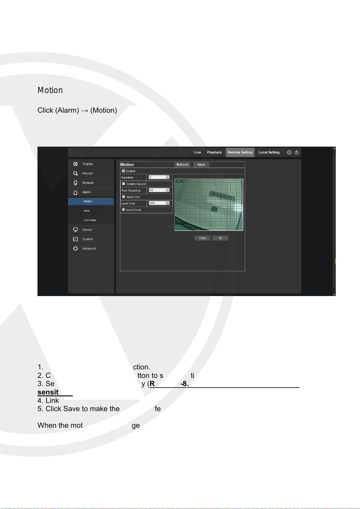
Motion
Click (Alarm) → (Motion)
Setting procedure:
1. Click to enable motion detection.
2. Click and drag left mouse button to select motion detection area.
3. Set motion detection sensitivity (Range: 1-8. Larger number indicates higher
sensitivity.)
4. Link SMTP to send by Email
5. Click Save to make the settings effective.
When the motion alarm is triggered, the screen on the live interface will appear with a green
character “M”.
31
Page 35
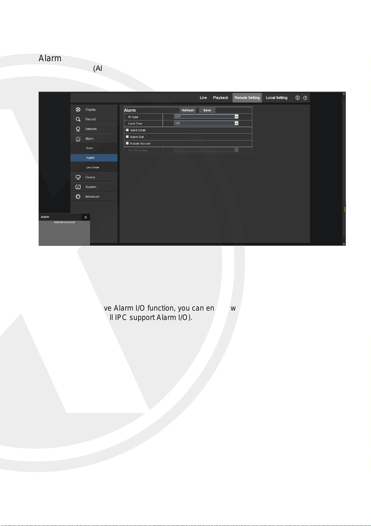
Alarm
Click (Alarm) → (Alarm)
Some of the IPC have Alarm I/O function, you can enable what happens when these are
triggered here. (Not all IPC support Alarm I/O).
32
Page 36
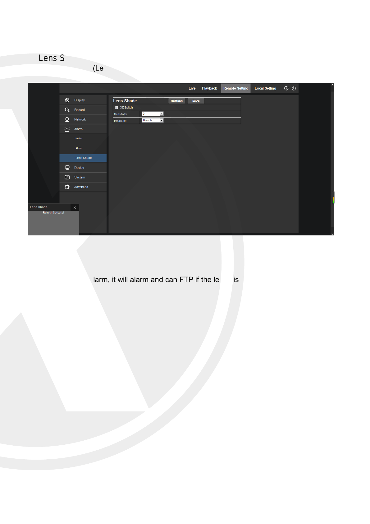
Lens Shade
Click (Alarm) → (Lens Shade)
This is a smart alarm, it will alarm and can FTP if the lends is blocked.
33
Page 37
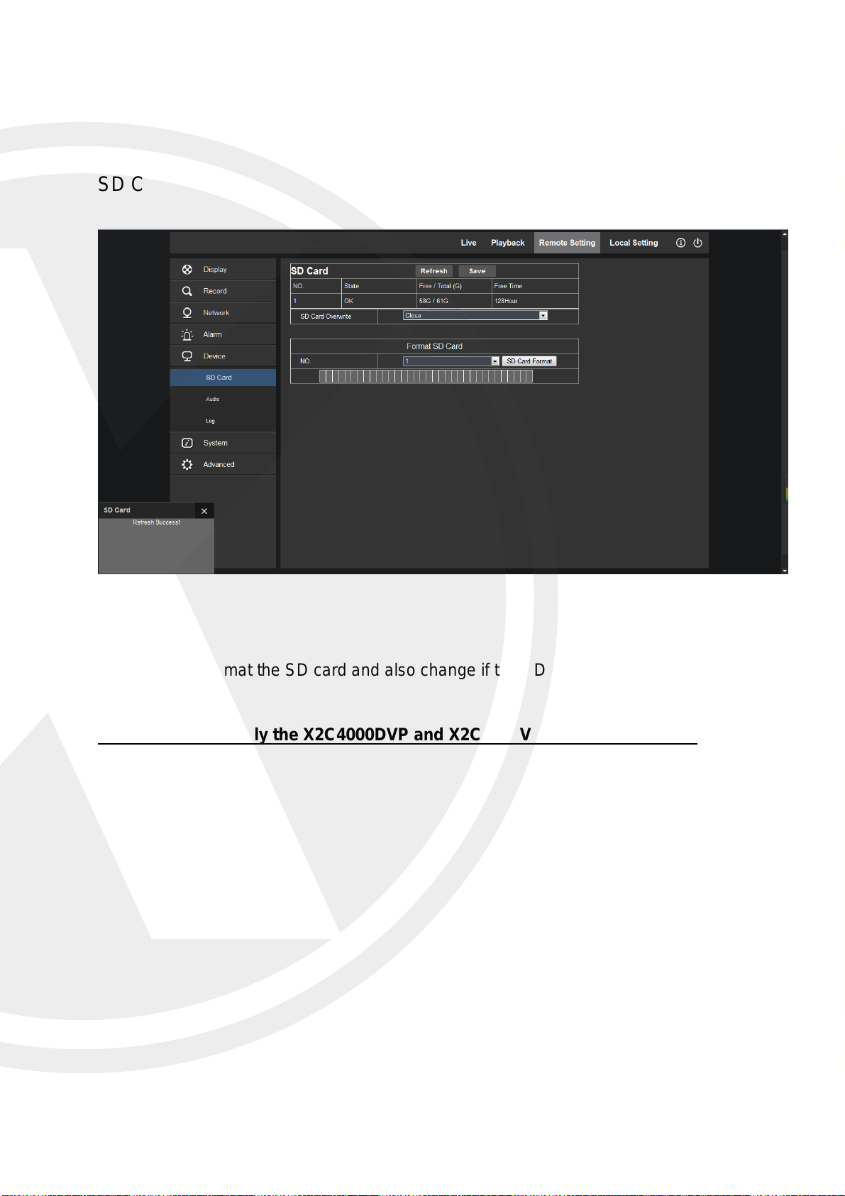
Device
SD Card
Here you can format the SD card and also change if the SD card is overwritten.
Please note that only the X2C4000DVP and X2C4000VAP support SD card.
34
Page 38
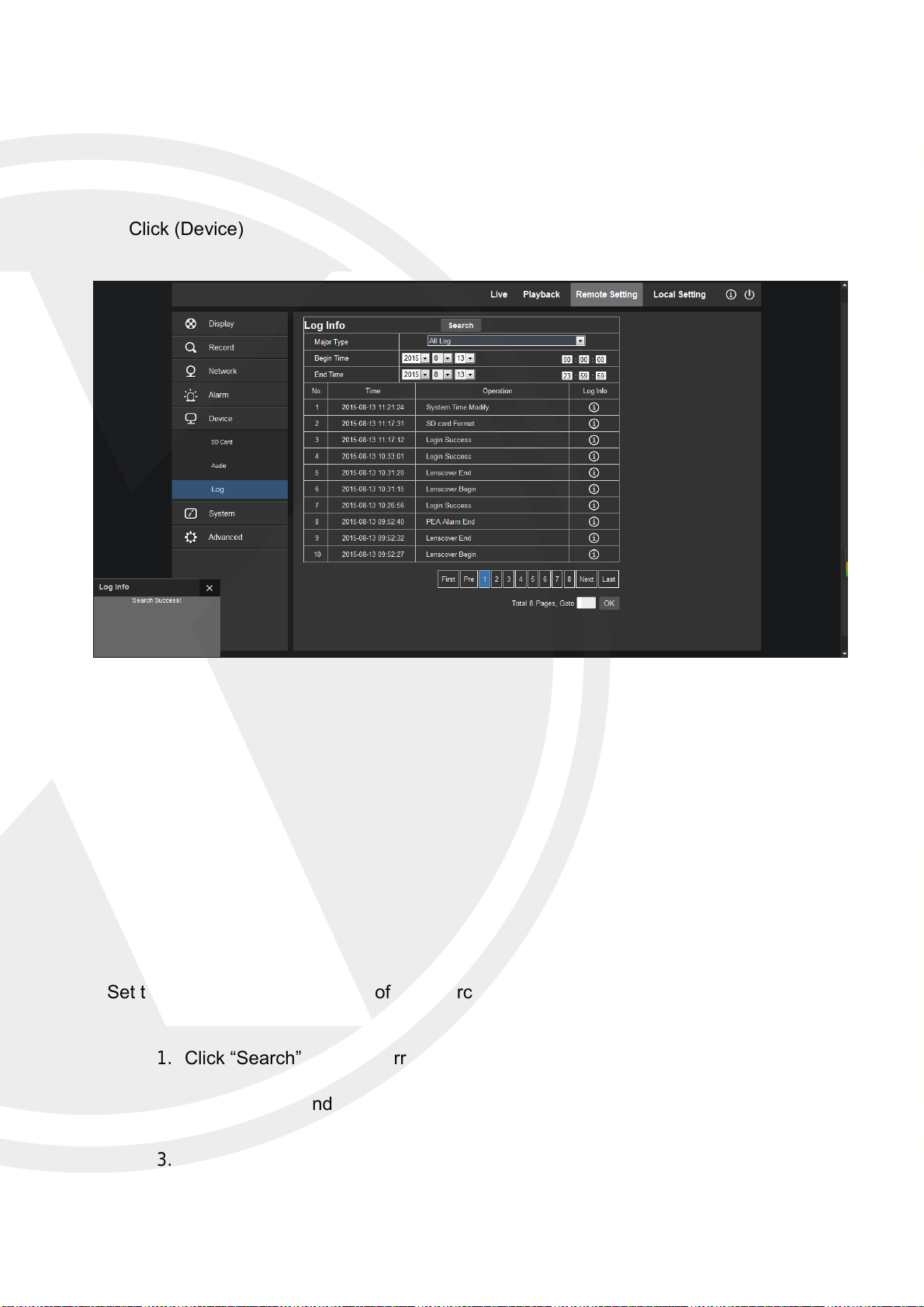
Log
Click (Device) → (Log)
Log Type:
System Log
Parameter Log
Alarm Log
Storage Log
All Log
Set the begin time and end time of the searched log.
1. Click “Search” and the corresponding log information will be displayed below;
2. Click “Delete” and the device log will be removed;
3. Click “Refresh” and the selected log information will be refreshed.
35
Page 39
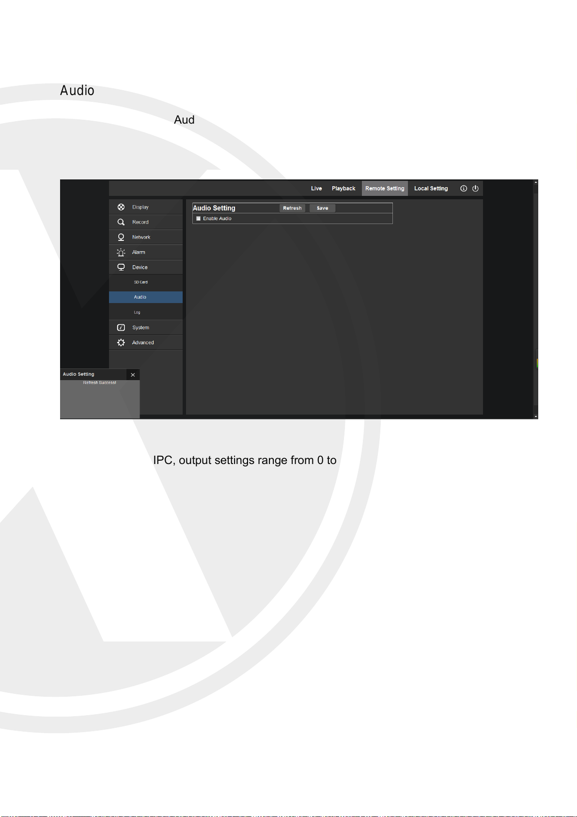
Audio
Click (Device) → (Audio)
Audio settings for IPC, output settings range from 0 to 10
36
Page 40
System
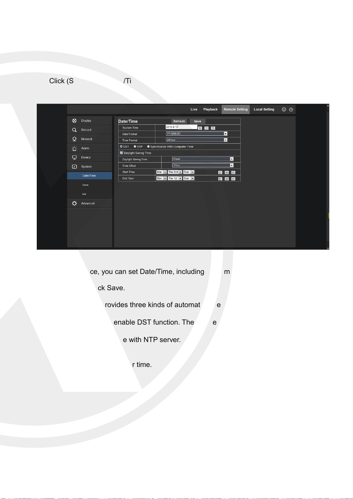
Date/Time
Click (System) → (Date/Time)
In this interface, you can set Date/Time, including System Time, Date Format and Time
Format.
After setting, click Save.
The device also provides three kinds of automatic time synchronization:
DST :Click DST to enable DST function. The device will synchronize time.
NTP :Synchronize time with NTP server.
Synchronize with computer time.
37
Page 41
Users
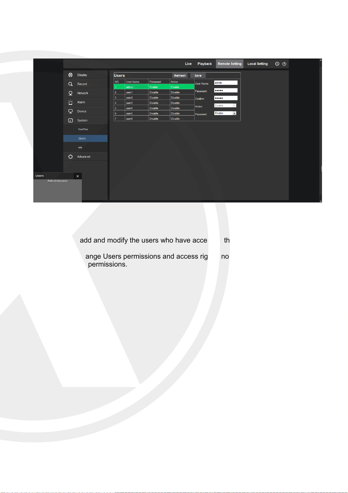
Click (System) → (Users)
Here you can add and modify the users who have access to the IPC.
You can also change Users permissions and access rights, note that you cannot change the
Admin accounts permissions.
38
Page 42
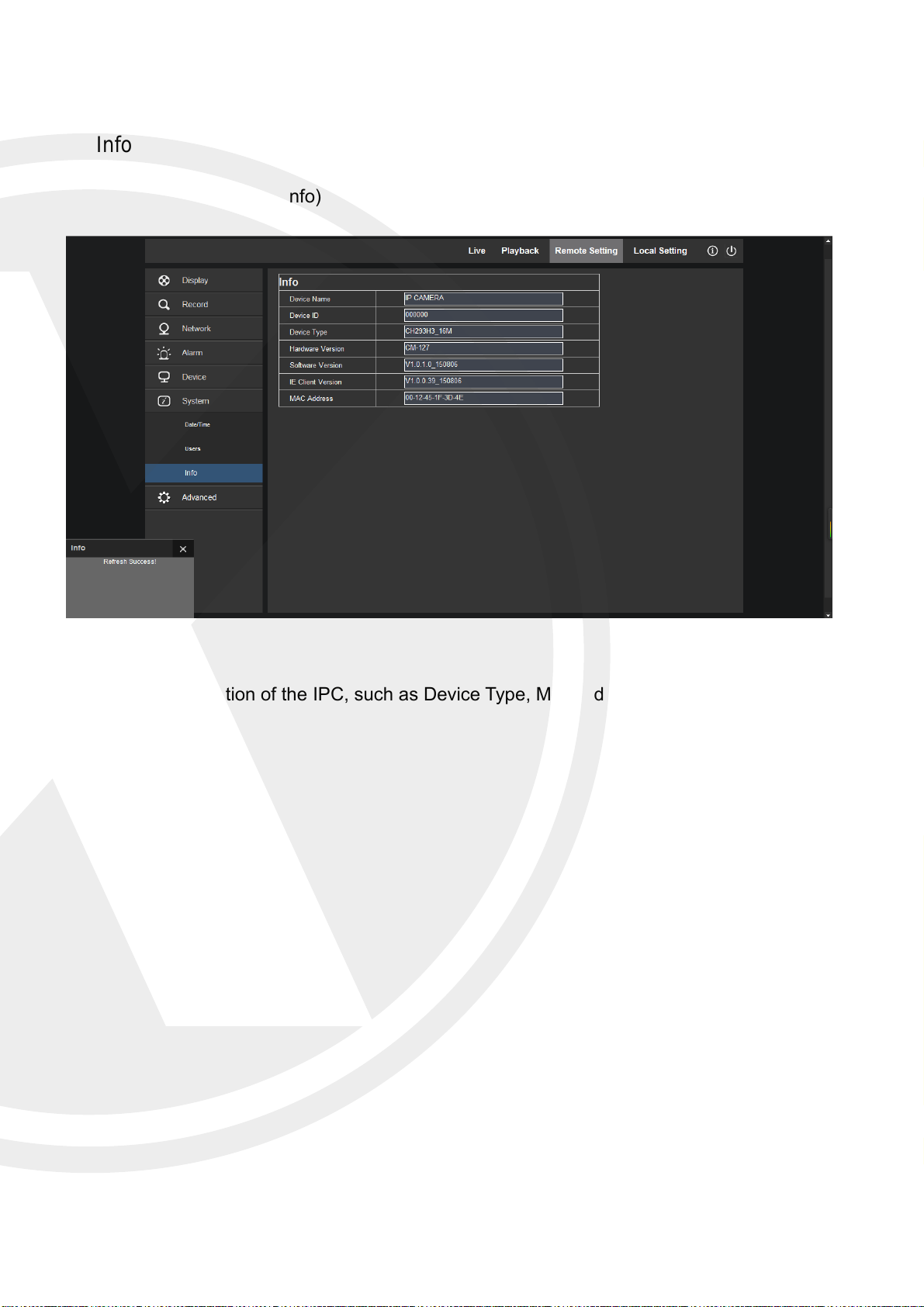
Info
Click (System) → (Info)
System information of the IPC, such as Device Type, MAC Address, Software Version,
Etc.
39
Page 43
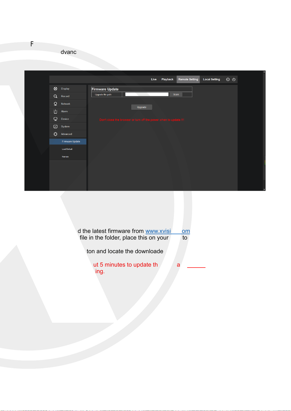
Advanced
Firmware Update
Click (Advanced) → (Firmware Update)
You can download the latest firmware from www.xvision.com, once downloaded you will
need to unzip the file in the folder, place this on your desktop or downloads folder.
Press the “Scan” button and locate the downloaded file.
Note: It will take about 5 minutes to update the firmware Do not remove power or
network during updating.
40
Page 44
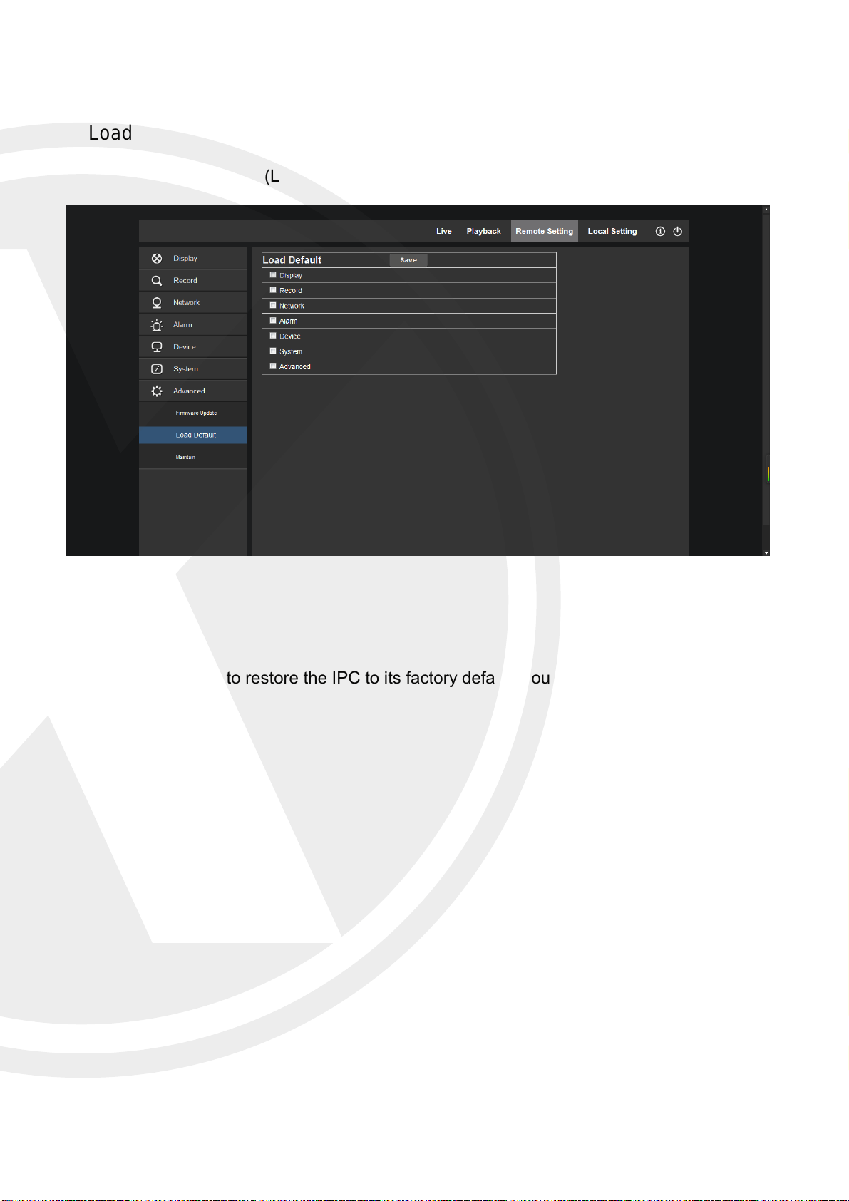
Load Default
Click (Advanced) → (Load Default)
Use this option to restore the IPC to its factory default, you can also default only certain
options.
41
Page 45
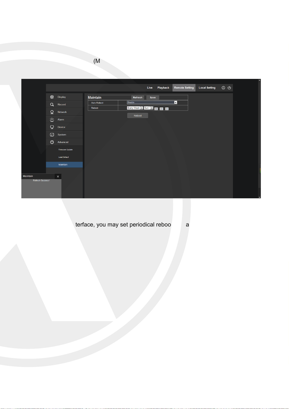
Maintain
Click (Advanced) → (Maintain)
In “Maintain” interface, you may set periodical reboot or manual reboot.
42
Page 46
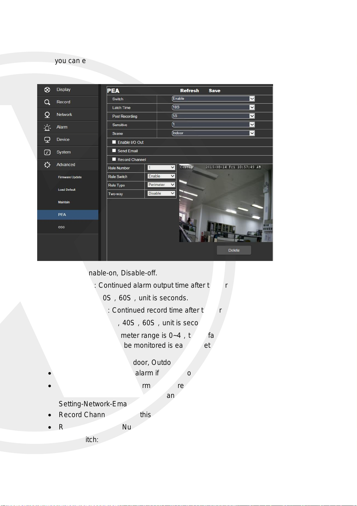
PEA (Perimeter Alarm)
Here you can enable the PEA.
Switch: Enable-on, Disable-off.
Latch Time: Continued alarm output time after trigger alarm, the optional time can be
10S,20S,40S,60S,unit is seconds.
Post Recording: Continued record time after trigger alarm finished, the optional time
can be 10S,20S,40S,60S,unit is seconds.
Sensitive: The parameter range is 0~4,the default value is 2. If set the sensitive is
higher, the object to be monitored is easy to detect, but also it may give you more
false triggers.
Scene: Scene setup, Indoor, Outdoor.
Enable I/O Out: Trigger alarm if with I/O output.
Send Email: When the alarm is triggered, then an email will be sent to notify. You will
need to enable the email function and server information, you can find this in (Remote
Setting-Network-Email).
Record Channel: Record this channel.
Rule Number: Rule Number, maximum 4.
Rule Switch: Every rule switch, Enable-on, Disable-off.
43
Page 47
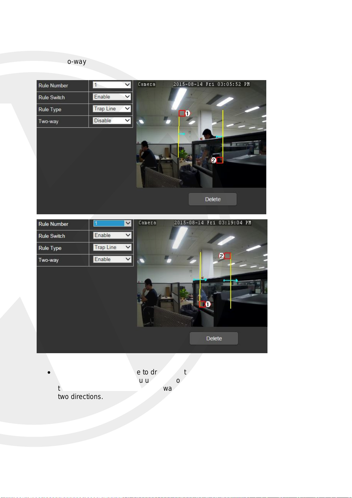
Rule Type: Every rule with a type, Trap Wire-draw warning line, Perimeter-draw
perimeter.
Two-way: Detection when line is crossed 2 ways.
Trap Wire: Use the mouse to draw from top to bottom, this will detect the object come
from left to right. When you use the mouse to draw from bottom to top, this will detect
the object from right to left. If two-way is open, then it will detect the object come from
two directions.
44
Page 48
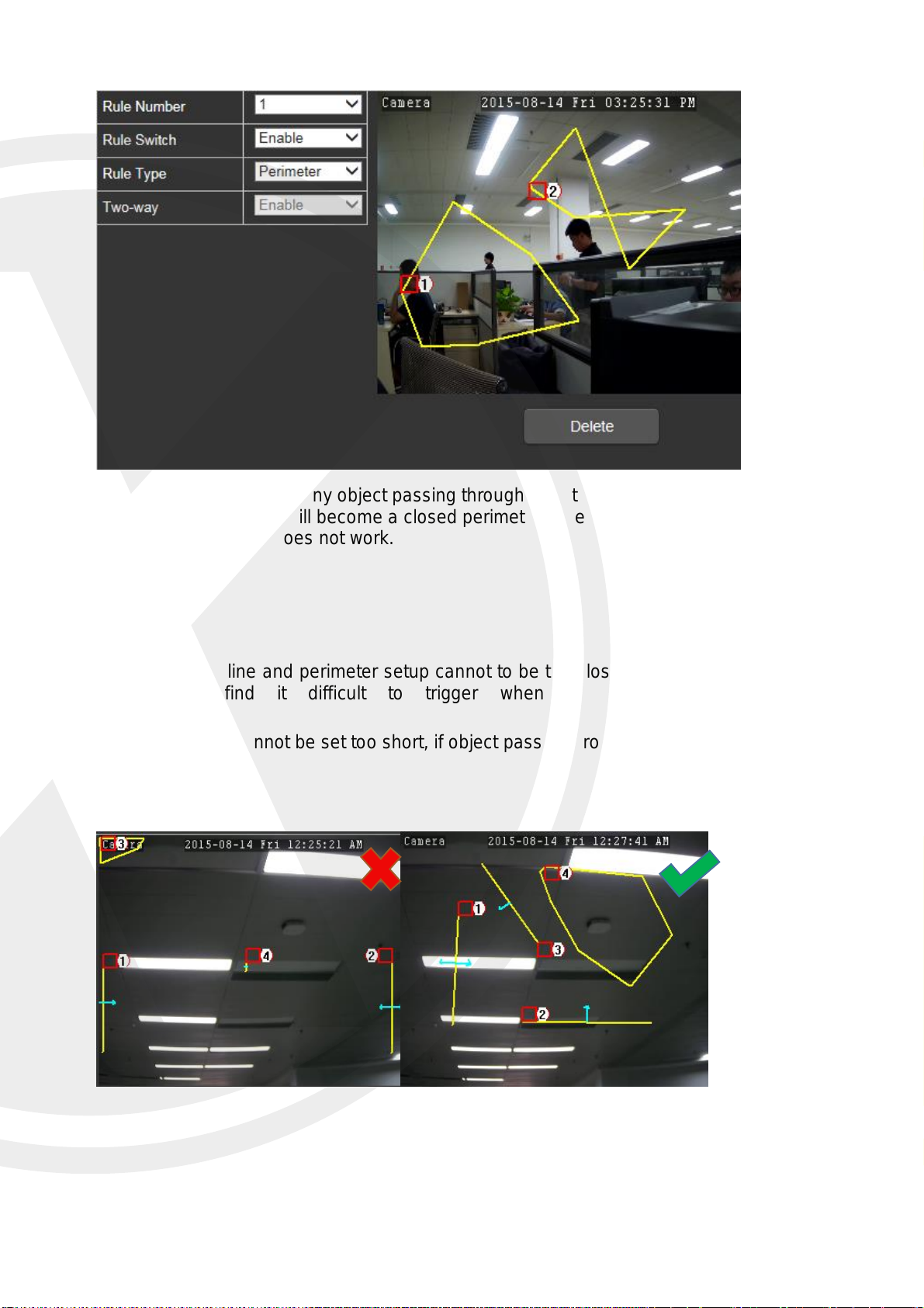
Perimeter: Detect any object passing through from this area, use the mouse to place
7 positions, this will become a closed perimeter, when Rule Type set to Perimeter,
then Two-way does not work.
Notice:
1) Warning line and perimeter setup cannot to be too close to the four side of video, the
IPC will find it difficult to trigger when an object passes through it.
2)Warning line cannot be set too short, if object passes through from the outside of it, no
alarm will trigger.
45
Page 49
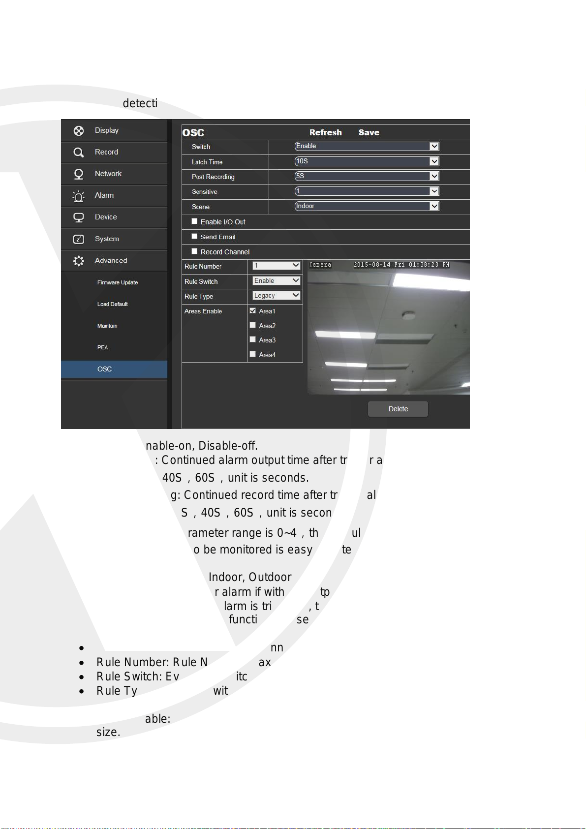
OSC –Object Care
Object loss detection.
Switch: Enable-on, Disable-off.
Latch Time: Continued alarm output time after trigger alarm, the optional time can be
10S,20S,40S,60S,unit is seconds.
Post Recording: Continued record time after trigger alarm finished, the optional time
can be 10S,20S,40S,60S,unit is seconds.
Sensitive: The parameter range is 0~4,the default value is 2. If set the sensitive is
higher, the object to be monitored is easy to detect, but also it may give you more
false triggers.
Scene: Scene setup, Indoor, Outdoor
Enable I/O Out: Trigger alarm if with I/O output.
Send Email: When the alarm is triggered, then an email will be sent to notify. You will
need to enable the email function and server information, you can find this in (Remote
Setting-Network-Email).
Record Channel: Record this channel.
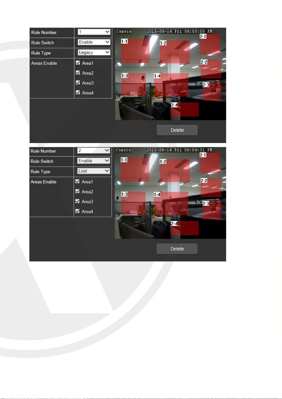
Rule Number: Rule Number, maximum 4.
Rule Switch: Every rule switch, Enable-on, Disable-off.
Rule Type: Every rule with a type, Legacy-detect if leave behind, Lost-detect if get
lost.
Areas Enable: Every rule to be related quantity to be setup, drag mouse to set zone
size.
46
Page 50
47
Page 51
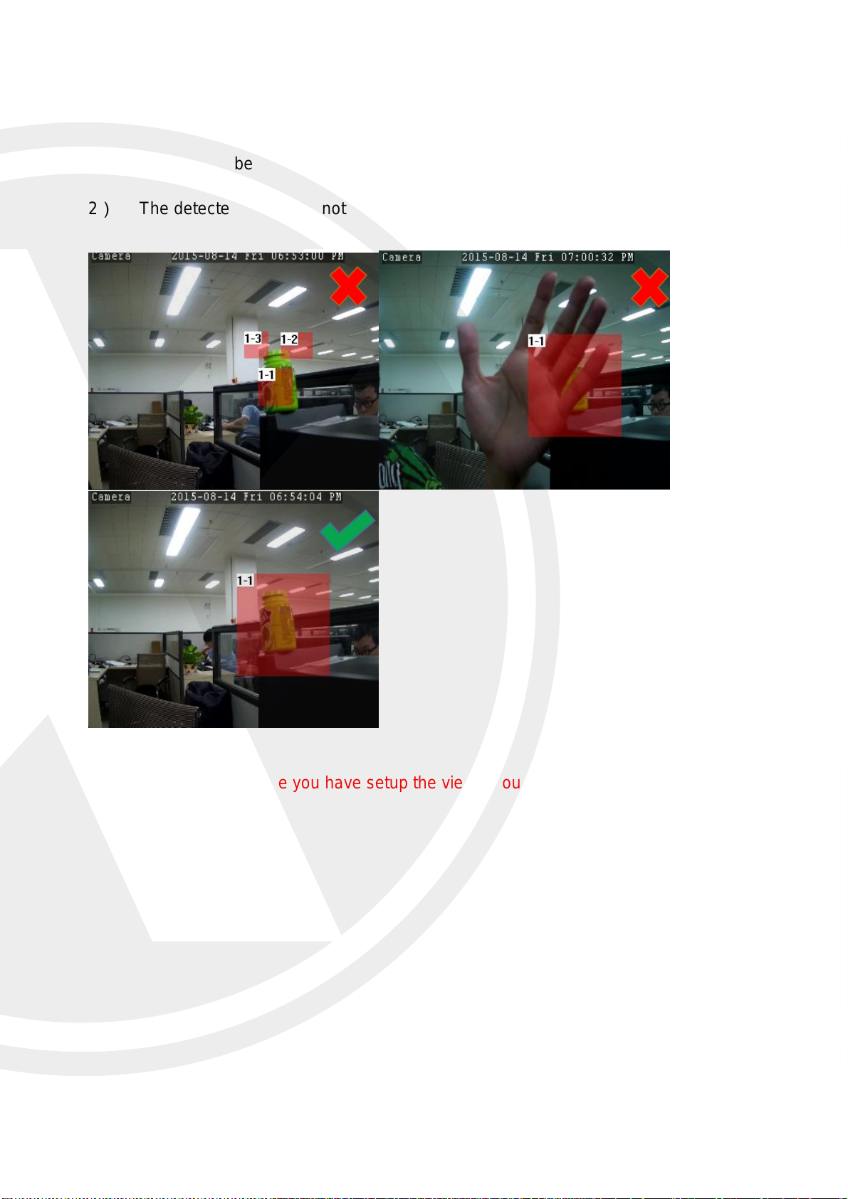
Notice:
1) The zone to be detected needs to be larger than the object, example of how not to set,
2) The detected object cannot be covered by other things.
Tips Remember that once you have setup the view if you move the IPC you will need to
reset the PEA and OSC.
48
Page 52
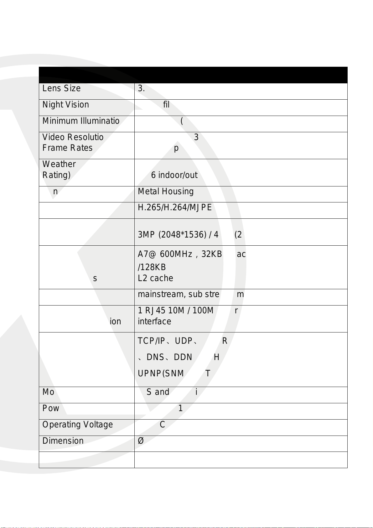
Model
X2C4000BP
Lens Size
3.6mm
Night Vision
IR cut filter with auto switch
Minimum Illumination
0.03Lux @(F1.2,AGC ON) ,0 Lux with IR
Video Resolution &
Frame Rates
3MP (2048*1536) / Real-Time (50HZ:25fps
60HZ:30fps ); 4MP Half real time
Weather Resistant (IP
Rating)
IP66 indoor/outdoor
Vandal Resistant
Metal Housing
Video Compression
H.265/H.264/MJPEG
Image Sensor
Resolution
3MP (2048*1536) / 4MP (2592*1520)
DSP Features
A7@ 600MHz,32KB I-Cache,32KB D-Cache
/128KB
L2 cache
Video Streams
mainstream, sub stream, mobile stream
Network Connection
1 RJ45 10M / 100M Ethernet interface and 1 RS-485
interface
Network Protocols
TCP/IP、UDP、RTP/RTCP、RTSP、HTTP、SMTP
、DNS、DDNS、DHCP、FTP、NTP、PPPOE、
UPNP(SNMP、HTTPS、
Mobile Phone Support
iOS and Android system - XIQCMS
Power Over Ethernet
12 VDC ± 10%, PoE
Operating Voltage
12VDC
Dimensions (mm)
Ø68x154.5mm
Weight (Kg)
350g
X2C4000 Specification’s
49
Page 53
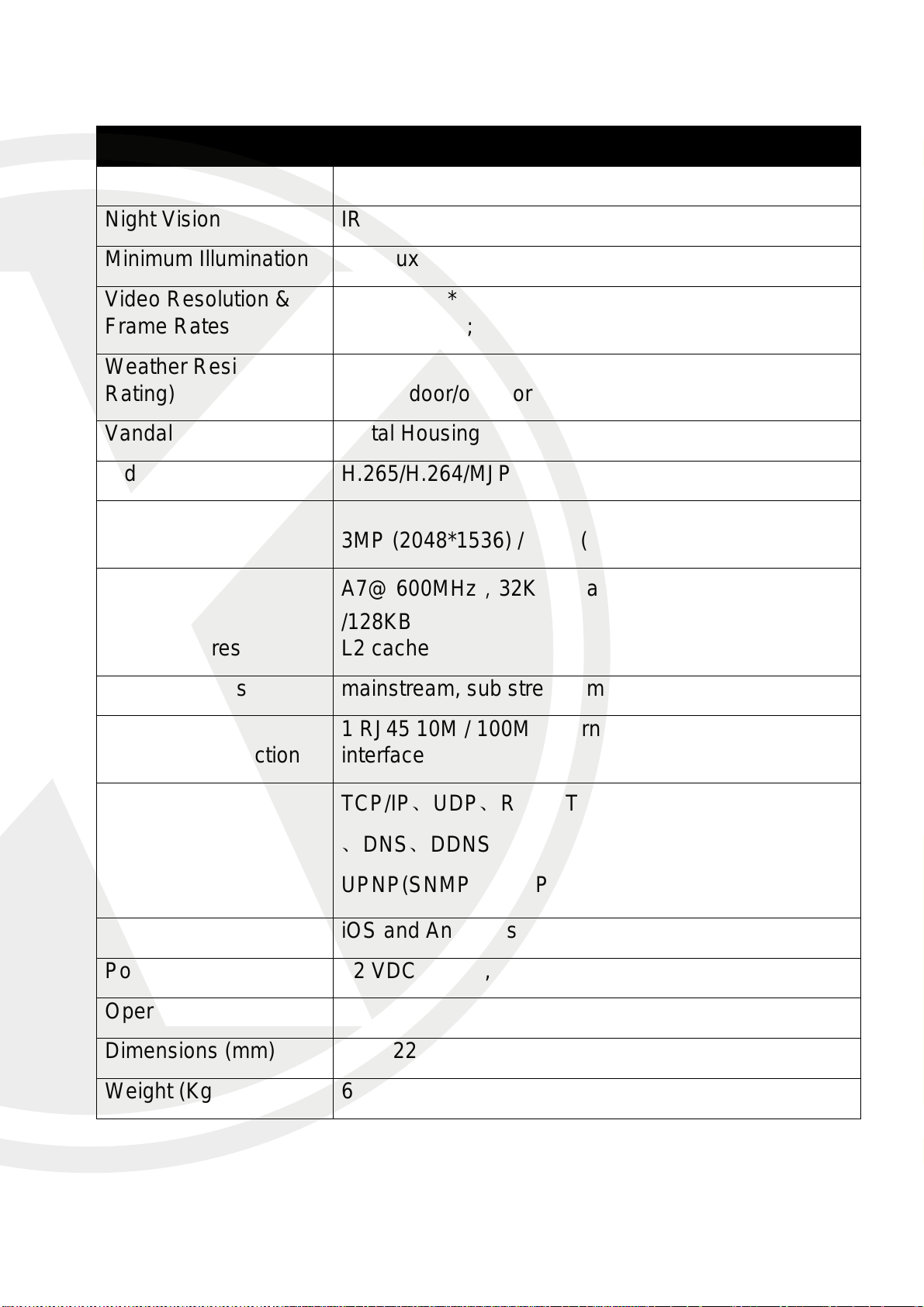
Model
X2C4000BVP
Lens Size
2.8-12mm
Night Vision
IR cut filter with auto switch
Minimum Illumination
0.03Lux @(F1.2,AGC ON) ,0 Lux with IR
Video Resolution &
Frame Rates
3MP (2048*1536) / Real-Time (50HZ:25fps
60HZ:30fps ); 4MP Half real time
Weather Resistant (IP
Rating)
IP66 indoor/outdoor
Vandal Resistant
Metal Housing
Video Compression
H.265/H.264/MJPEG
Image Sensor
Resolution
3MP (2048*1536) / 4MP (2592*1520)
DSP Features
A7@ 600MHz,32KB I-Cache,32KB D-Cache
/128KB
L2 cache
Video Streams
mainstream, sub stream, mobile stream
Network Connection
1 RJ45 10M / 100M Ethernet interface and 1 RS-485
interface
Network Protocols
TCP/IP、UDP、RTP/RTCP、RTSP、HTTP、SMTP
、DNS、DDNS、DHCP、FTP、NTP、PPPOE、
UPNP(SNMP、HTTPS、
Mobile Phone Support
iOS and Android system - XIQCMS
Power Over Ethernet
12 VDC ± 10%, PoE
Operating Voltage
12VDC
Dimensions (mm)
Ø75x220mm
Weight (Kg)
638g
50
Page 54
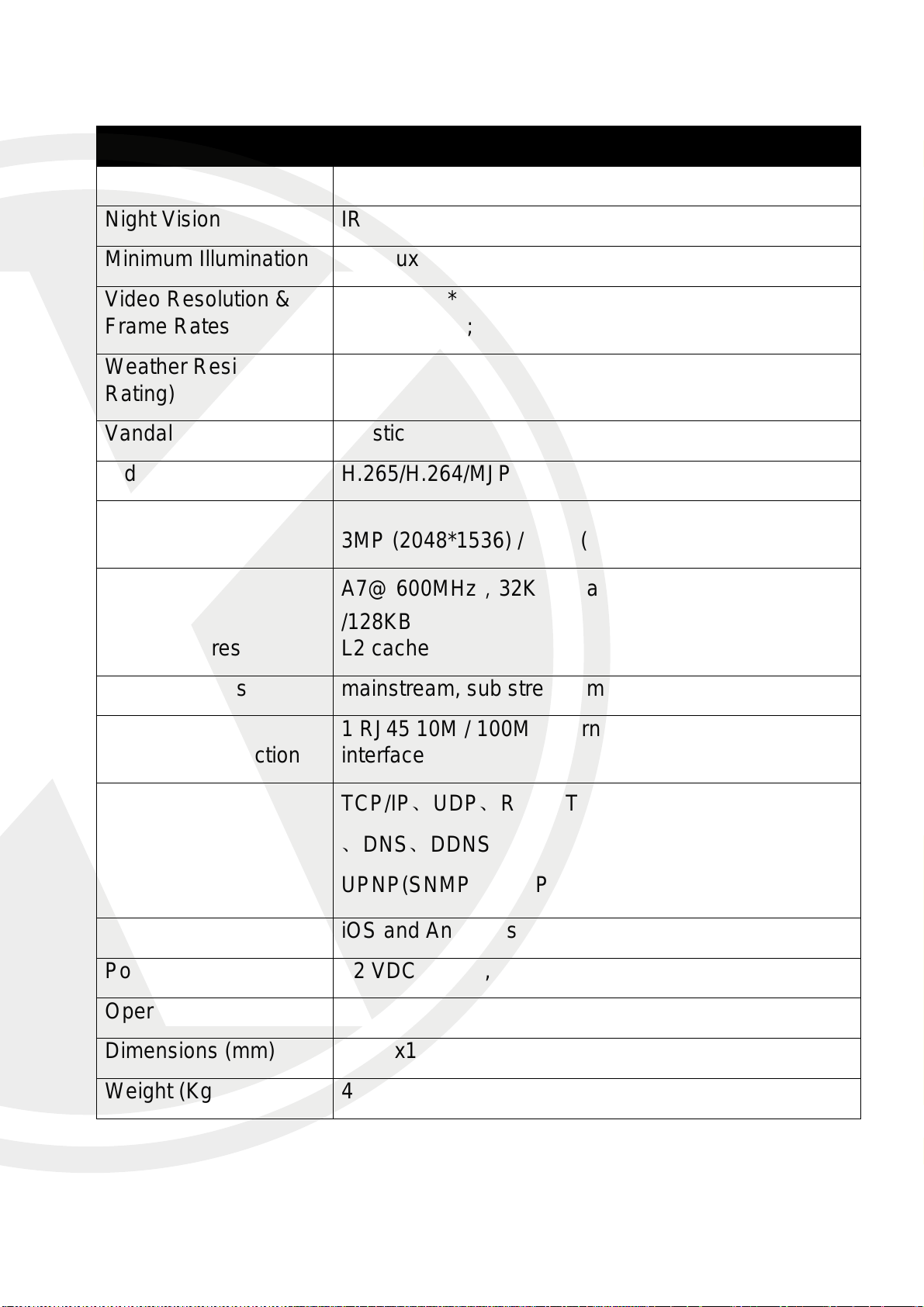
Model
X2C4000DVP
Lens Size
2.8-12mm
Night Vision
IR cut filter with auto switch
Minimum Illumination
0.03Lux @(F1.2,AGC ON) ,0 Lux with IR
Video Resolution &
Frame Rates
3MP (2048*1536) / Real-Time (50HZ:25fps
60HZ:30fps ); 4MP Half real time
Weather Resistant (IP
Rating)
Indoor
Vandal Resistant
Plastic
Video Compression
H.265/H.264/MJPEG
Image Sensor
Resolution
3MP (2048*1536) / 4MP (2592*1520)
DSP Features
A7@ 600MHz,32KB I-Cache,32KB D-Cache
/128KB
L2 cache
Video Streams
mainstream, sub stream, mobile stream
Network Connection
1 RJ45 10M / 100M Ethernet interface and 1 RS-485
interface
Network Protocols
TCP/IP、UDP、RTP/RTCP、RTSP、HTTP、SMTP
、DNS、DDNS、DHCP、FTP、NTP、PPPOE、
UPNP(SNMP、HTTPS、
Mobile Phone Support
iOS and Android system - XIQCMS
Power Over Ethernet
12 VDC ± 10%, PoE
Operating Voltage
12VDC
Dimensions (mm)
Ø145x115mm
Weight (Kg)
408g
51
Page 55
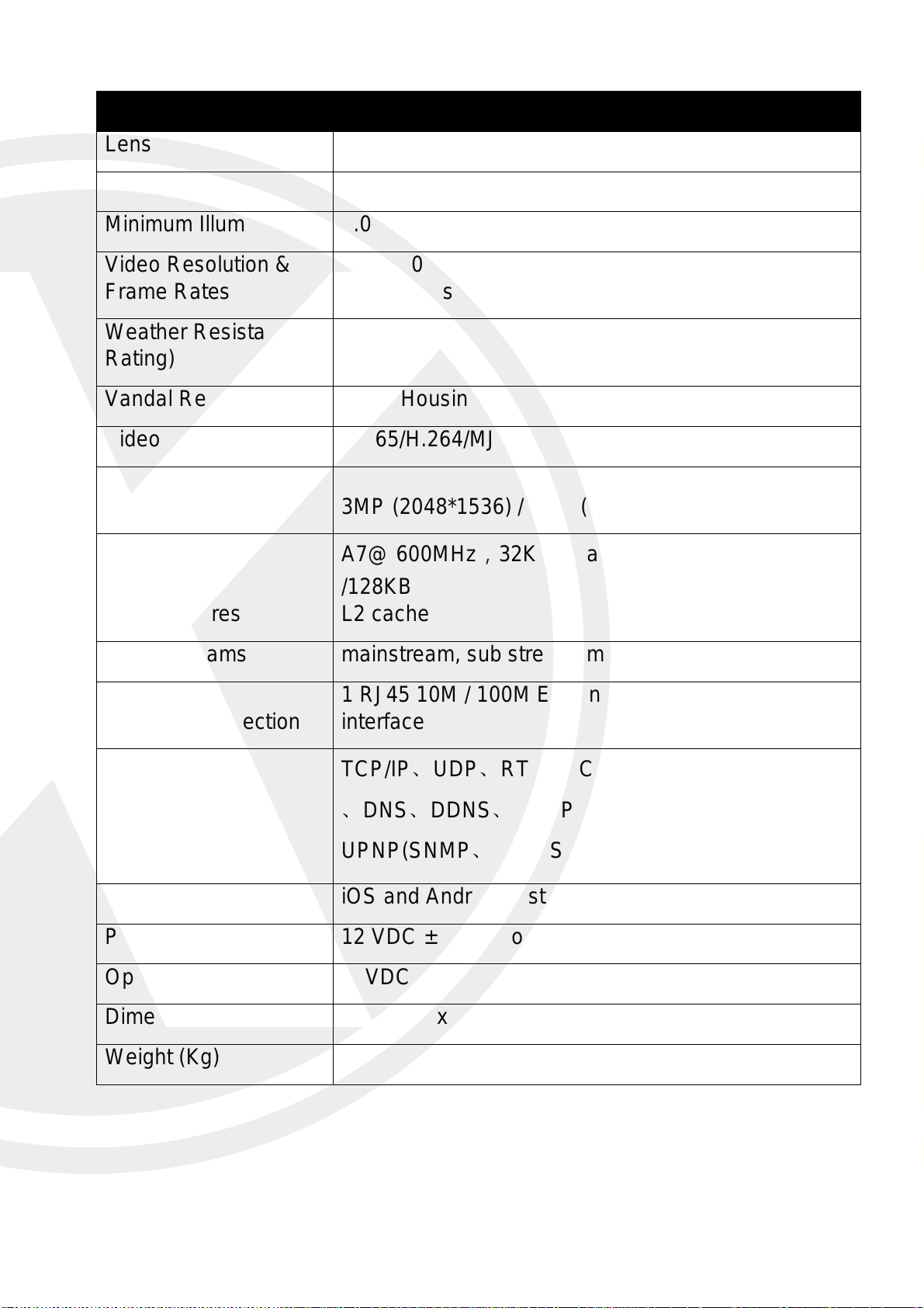
Model
X2C4000MP
Lens Size
3.6mm
Night Vision
IR cut filter with auto switch
Minimum Illumination
0.03Lux @(F1.2,AGC ON) ,0 Lux with IR
Video Resolution &
Frame Rates
3MP (2048*1536) / Real-Time (50HZ:25fps
60HZ:30fps ); 4MP Half real time
Weather Resistant (IP
Rating)
Indoor
Vandal Resistant
Metal Housing
Video Compression
H.265/H.264/MJPEG
Image Sensor
Resolution
3MP (2048*1536) / 4MP (2592*1520)
DSP Features
A7@ 600MHz,32KB I-Cache,32KB D-Cache
/128KB
L2 cache
Video Streams
mainstream, sub stream, mobile stream
Network Connection
1 RJ45 10M / 100M Ethernet interface and 1 RS-485
interface
Network Protocols
TCP/IP、UDP、RTP/RTCP、RTSP、HTTP、SMTP
、DNS、DDNS、DHCP、FTP、NTP、PPPOE、
UPNP(SNMP、HTTPS、
Mobile Phone Support
iOS and Android system - XIQCMS
Power Over Ethernet
12 VDC ± 10%, PoE
Operating Voltage
12VDC
Dimensions (mm)
99.7x99.1x56.8mm
Weight (Kg)
450g
52
Page 56
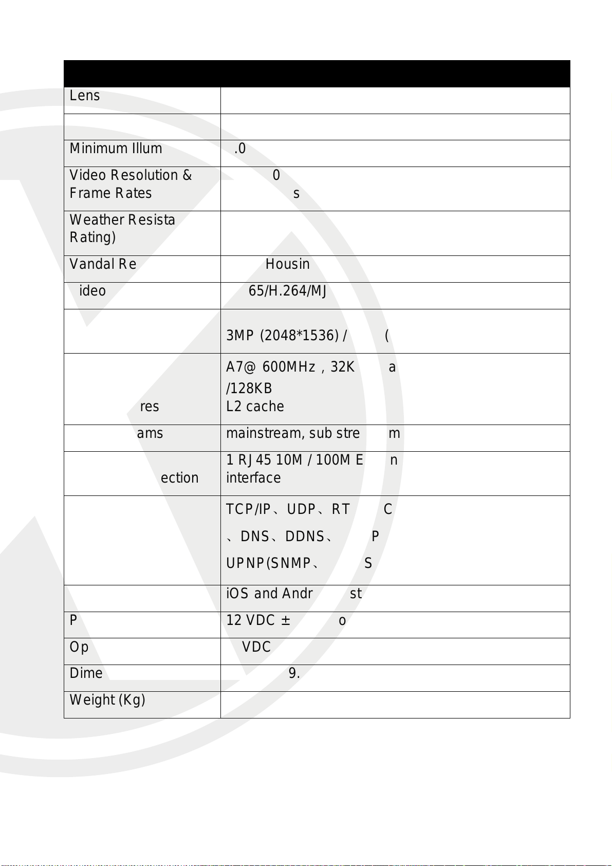
Model
X2C4000VP
Lens Size
3.6mm
Night Vision
IR cut filter with auto switch
Minimum Illumination
0.03Lux @(F1.2,AGC ON) ,0 Lux with IR
Video Resolution &
Frame Rates
3MP (2048*1536) / Real-Time (50HZ:25fps
60HZ:30fps ); 4MP Half real time
Weather Resistant (IP
Rating)
indoor
Vandal Resistant
Metal Housing
Video Compression
H.265/H.264/MJPEG
Image Sensor
Resolution
3MP (2048*1536) / 4MP (2592*1520)
DSP Features
A7@ 600MHz,32KB I-Cache,32KB D-Cache
/128KB
L2 cache
Video Streams
mainstream, sub stream, mobile stream
Network Connection
1 RJ45 10M / 100M Ethernet interface and 1 RS-485
interface
Network Protocols
TCP/IP、UDP、RTP/RTCP、RTSP、HTTP、SMTP
、DNS、DDNS、DHCP、FTP、NTP、PPPOE、
UPNP(SNMP、HTTPS、
Mobile Phone Support
iOS and Android system - XIQCMS
Power Over Ethernet
12 VDC ± 10%, PoE
Operating Voltage
12VDC
Dimensions (mm)
Ø126.6x89.8mm
Weight (Kg)
470g
53
Page 57
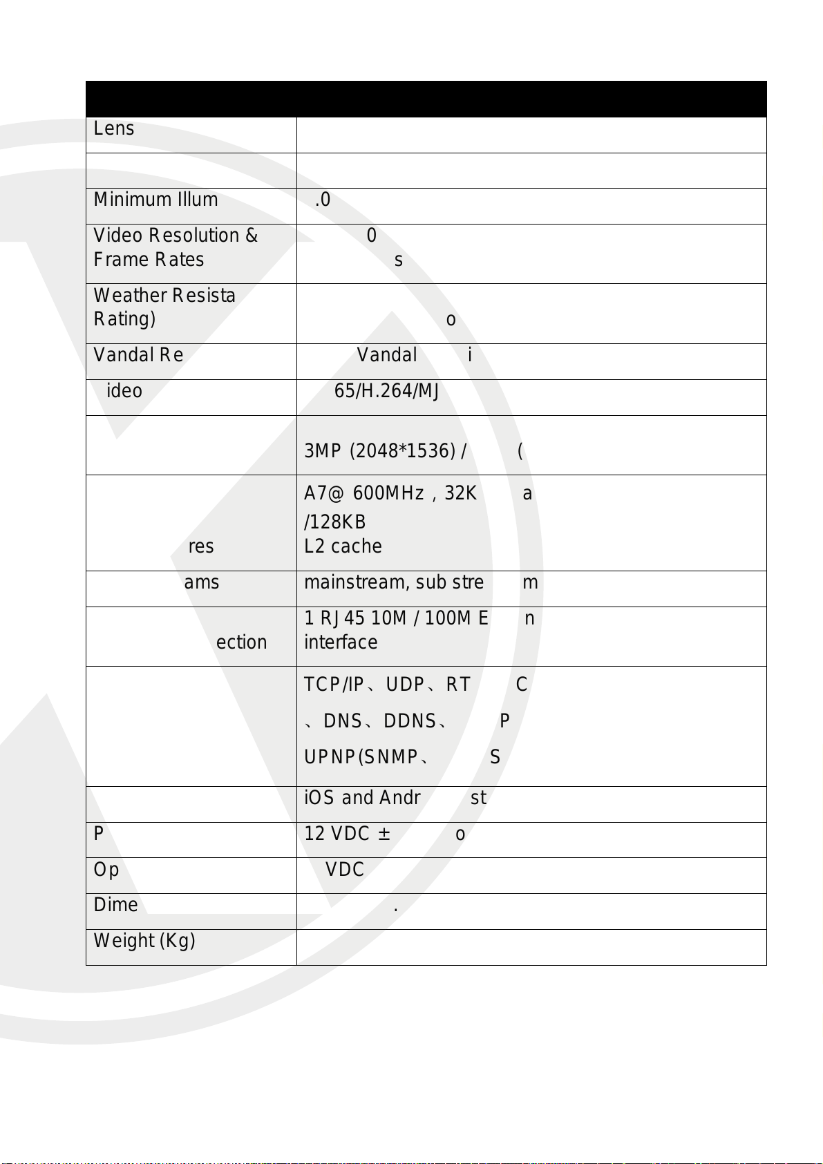
Model
X2C4000VAP
Lens Size
2.8-12mm
Night Vision
IR cut filter with auto switch
Minimum Illumination
0.03Lux @(F1.2,AGC ON) ,0 Lux with IR
Video Resolution &
Frame Rates
3MP (2048*1536) / Real-Time (50HZ:25fps
60HZ:30fps ); 4MP Half real time
Weather Resistant (IP
Rating)
IP66 indoor/outdoor
Vandal Resistant
Metal Vandal Housing
Video Compression
H.265/H.264/MJPEG
Image Sensor
Resolution
3MP (2048*1536) / 4MP (2592*1520)
DSP Features
A7@ 600MHz,32KB I-Cache,32KB D-Cache
/128KB
L2 cache
Video Streams
mainstream, sub stream, mobile stream
Network Connection
1 RJ45 10M / 100M Ethernet interface and 1 RS-485
interface
Network Protocols
TCP/IP、UDP、RTP/RTCP、RTSP、HTTP、SMTP
、DNS、DDNS、DHCP、FTP、NTP、PPPOE、
UPNP(SNMP、HTTPS、
Mobile Phone Support
iOS and Android system - XIQCMS
Power Over Ethernet
12 VDC ± 10%, PoE
Operating Voltage
12VDC
Dimensions (mm)
Ø147x111.3mm
Weight (Kg)
844g
54
Page 58
FAQ
No video stream on IE
Please check the Active x controls have been installed, make sure you have added
the IPC IP address to the list of trusted sites and amended your Active x controls.
Cannot find IPC on my LAN
Confirm that your PC IP Address is within the same IP Range as the default IP
Address range.
Also check your power supply and cable if using POE.
No live image on the XIQCMS
Try and connect to the IPC on your LAN first using the XIQCMS, if this work when
away from your IPC LAN; please connect to WIFI and try and connected. If this works
but over 3/4G you get no connection/image, please contact your mobile provider as
they may be blocking access on the XIQCMS mobile port 9988. You can also try and
change this port and then try and get access again.
For more help and guides please visit http://www.xvision.com
55
Page 59
Manufactured exclusively for:
PRO
www.xvision.com
TECHNICAL SUPPORT
For technical support, please contact your local distributor.
Alternatively, 0871 222 1430
LIMITED WARRANTY
This product is supplied with a 12 month warranty (extendable to 3 years).
The warranty excludes products that have been misused (including accidental damage)
and damage caused by normal wear and tear. In the unlikely event that you encounter a
problem with this product, it should be returned to the place of purchase.
Xvision UK, Unit 2 Valley Point, Beddington Farm Road, Croydon, Surrey CR0 4WP
www.xvision.com
 Loading...