

Page 1
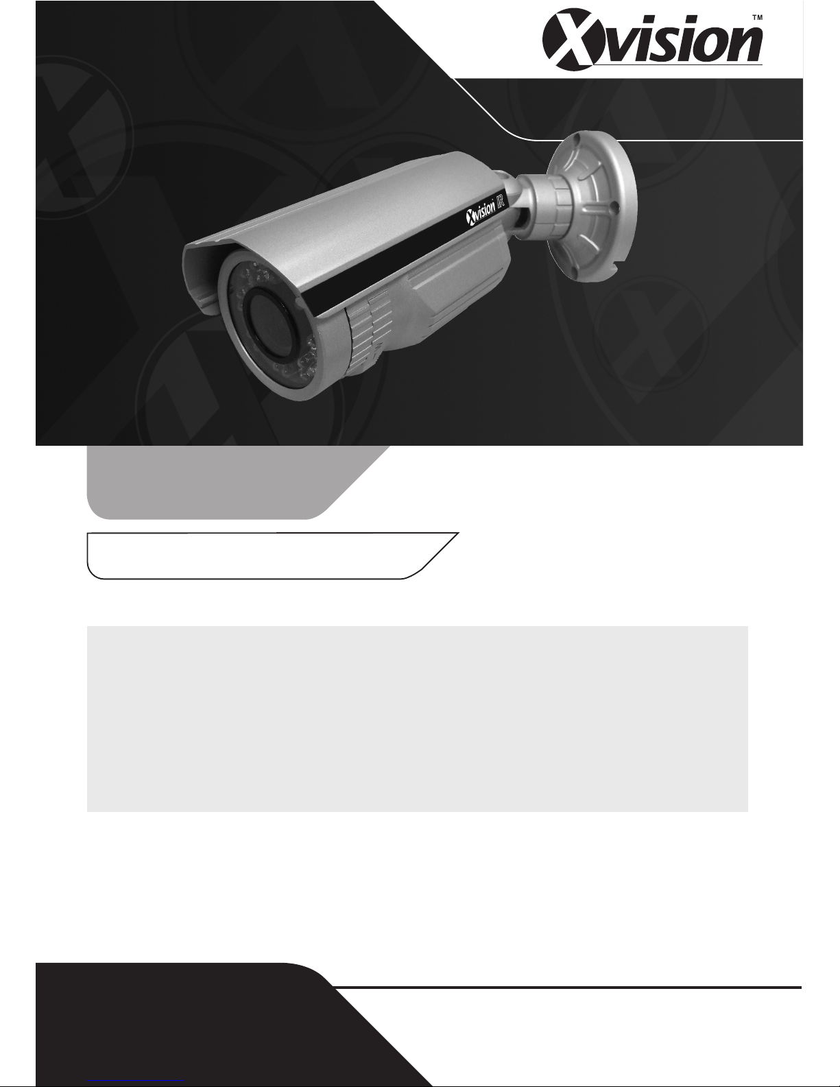
Model: VIS600E
Colour 60m True Day/Night
IR Nightvision Camera
CCTV
Model:
VIS600E
Colour True Day/Night Varifocal IR
Camera with 60 metres Nightvision
Before you begin
• Please unpack the box carefully and identify that all the parts are present.
• Do not cut the camera cables, this will void the warranty.
• Make sure you use only the recommended power supply. Damage caused to the camera by
incorrect voltage or wiring is not covered by the warranty.
The camera is suitable for indoor or outdoor use. Please bear in mind the following points when
choosing a mounting position.
•The camera must be positioned so that it will not point directly into the sun (sunrise and
sunset) or any bright light, as this may cause damage to the camera.
•Avoid viewing areas where half the area is in bright sunlight and the other half is dark,
such as in the shadow of a building. All types of cameras have difficulty in ‘seeing’ with
such a large lux level variation.
Page 2
2
Thank you for purchasing this Xvision camera. Before operating this
product, please read this instruction manual carefully.
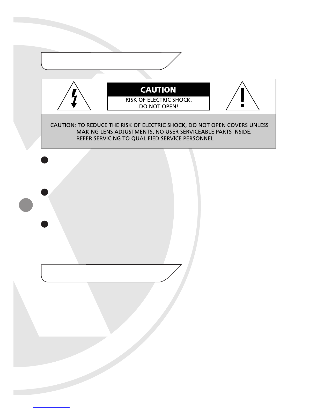
When in use please avoid direct contact with eyes and do not touch
the camera body as it can get very hot.
When installing the camera, please avoid pointing it directly at
paper or flammable materials.
Please avoid all direct contact with the tempered glass cover to
avoid contamination. If you need to clean the cover use cotton wool
balls dipped in alcohol or glass wipes.
The VIS600E colour long range IR camera is designed for high risk
applications. It offers very high resolution 550 TVL images from its Sony
1/3" Ex View CCD sensor and will provide images in complete darkness
up to 60 metres and beyond 60 metres in light levels above 0.002 lux.
It features a Varifocal Auto Iris Lens and cable managed bracket and is
designed for internal or external use. The camera features a Mechanical
IR Filter for True Day Night images and a 3 axis bracket allowing it to
be mounted on a wall or ceiling.
1. Safety Precautions
2. Product Description
Page 3
Sony 1/3" Ex View CCD image sensor for 550 TVL resolution images and
0.002 lux low light sensitivity
Samsung DSP Chip & Xvision X3 DSP Software
Varifocal Aspherical IR Optimised Auto Iris 2.8 to 11.0mm lens with 26° to
92° viewing angle for super sharp images and easy selection of the optimum
viewing angle during installation.
Mechanical IR Filter for True Day Night Images, with excellent colour
reproduction during the day and no focus shift.
Integrated Long Life Infra Red High Intensity LEDs turn on automatically in
low light conditions or complete darkness and provide up to 60 metres
Nightvision.
Dynamic Night View technology provides clear images without the need for
IR LEDs down to 0.002 lux, this is achieved by using a Digital Slow Shutter,
please note due to the way in which this technology works, whilst it is in
operation the frames per second will reduce. The darker the scene the lower
the frames per second, resulting in a non real time image.
DNR (Digital Noise Reduction) reduces the noise on the image when viewing
in low lux environments (like at night), this reduces the size of the image
when being recorded by a DVR, resulting in a saving of disk space.
3. Features
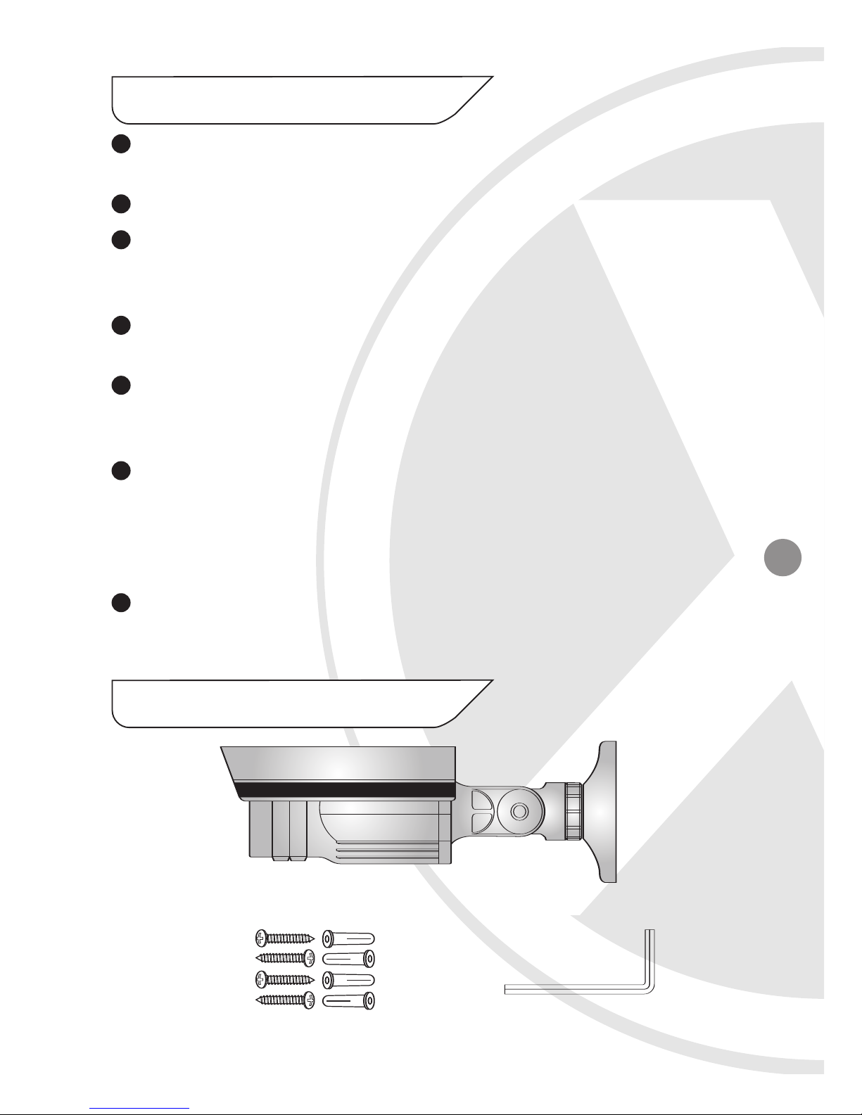
4. Contents
VIS600E Camera
Hex Wrench
4x Fixing Screws 4x Wall Plugs
3
Page 4
4
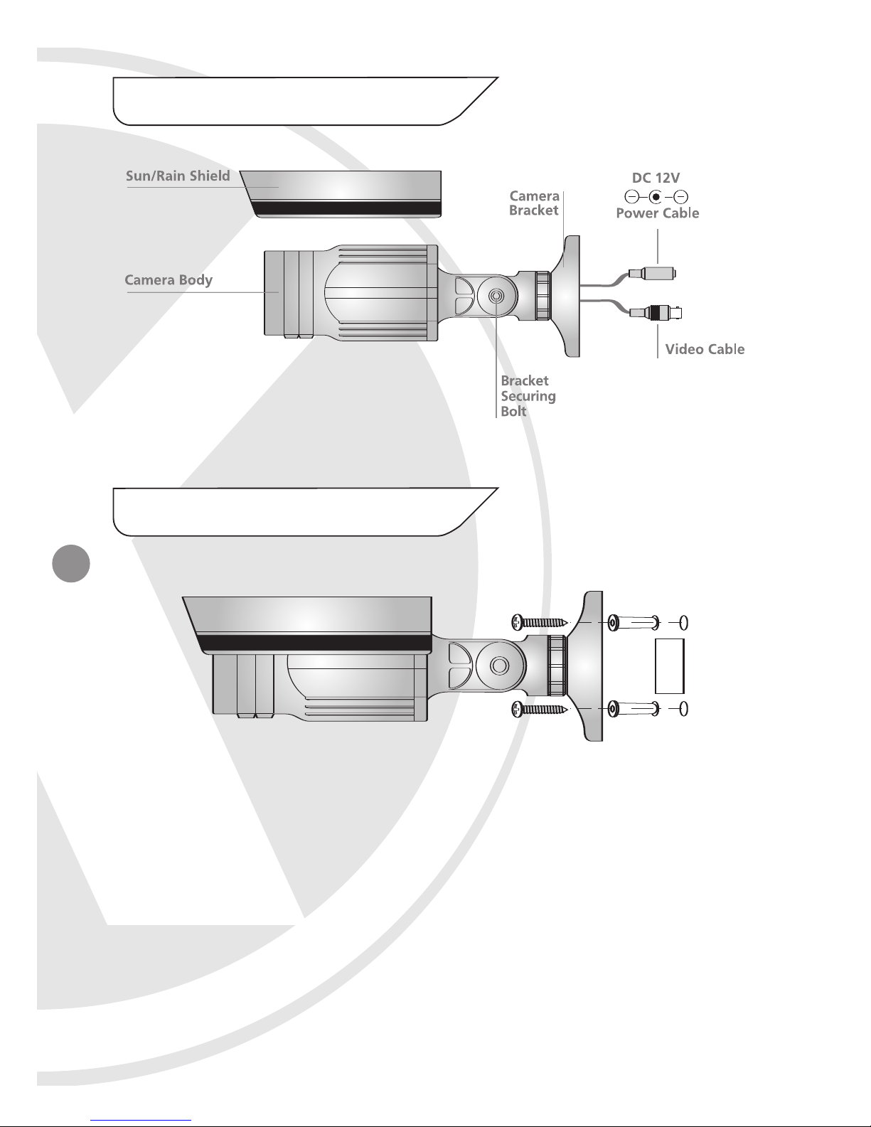
Figure 1
5. Product Assembly
6. Installation
1. Make a hole in the wall approximately 30mm wide x 40mm deep.
2. Drill 4 holes and insert the wall plugs.
3. Feed the cables into the wall before fixing the camera using the
4 fixing screws
Figure 2
Page 5
5
1. Connect the video output to the monitor or other video device
through a 75 Ohms type coaxial cable.
2. Connect the power source, insert the AC plug into the AC socket and
the DC plug into the DC Jack (+12V DC in jack centre).
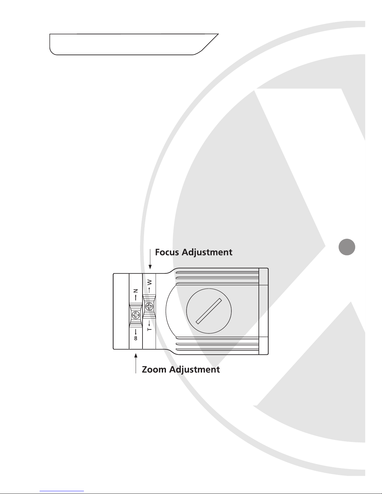
3. Once the picture appears on the monitor, find the adjustment rings on
the base of the camera. Loosen the screw and make the Zoom
Adjustment by rotating the ring (NEAR-Anti-clockwise, FAR-Clockwise)
until you get the desired view, then tighten the screw. Next make the
Focal Adjustment by loosening the screw and rotating the ring (TELEAnti-clockwise, WIDE-Clockwise) until you get the desired view, then
tighten the screw (as shown in Figure 3).
7. How to Operate
Figure 3
Page 6
6
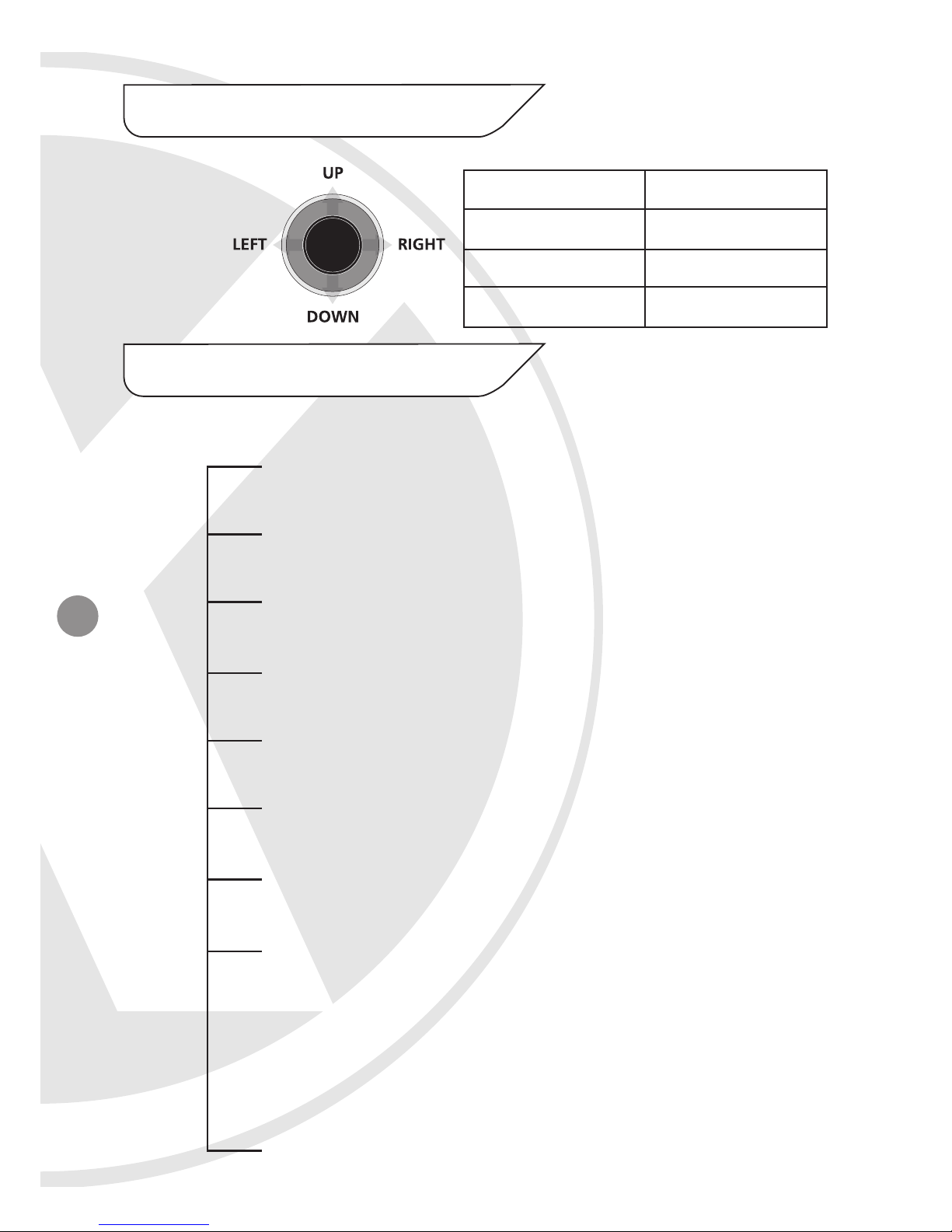
Press this Control
UP, DOWN
LEFT, RIGHT
SETUP (MENU)
Action
Select a new item
Select a menu item
Access a sub menu
8. Camera OSD Control
9. OSD Menu Structure
Push
DOWN
to Setup
menu
LENS Option
● DC ● MANUAL
SHUTTER
● OFF ● FLK ● MANUAL ● ESC
WHITE BALANCE
● ATW ● AWC ● MANUAL
BACKLIGHT
● OFF ● LOW ● MIDDLE ● HIGH
AGC
● OFF ● LOW ● MIDDLE ● HIGH
DNR
● OFF ● LOW ● MIDDLE ● HIGH
SENS UP/DSS
● AUTO ● OFF
SPECIAL
● CAMERA ID ● COLOUR ● SYNC
● MOTION DET ● PRIVACY ● MIRROR
● SHARPNESS ● RESET ● RETURN
EXIT
SET UP MENU
Page 7

7
10. SETUP Menu Functions
1 LENS
<Option: DC / MANUAL>
Selects lens type.
2 SHUTTER
<Option: OFF / FLK / MANUAL/ ESC>
Adjusts shutter settings.
Flickerless mode (FLK) reduces on-screen flickering.
Electronic Shutter Control (ESC) adjusts brightness level on screen.
Manual mode allows you to adjust the shutter speed from
1/60~1/120,000 of a second (NTSC), or 1/50~1/120,000 (PAL).
FLK is the only option available when the camera lens is set to the
recommended DC mode.
3 WHITE BALANCE
<Option: ATC / AWC / MANUAL>
Controls colour on the screen.
Select Auto Tracking White Balance (ATW) when the colour
temp. is 2400°K~12000°K (for example when under a fluorescent
light or outdoors).
Manual mode allows you to increase or decrease the red or blue
factor on screen.
Auto White Balance Control (AWC) automatically adjusts the white
balance to your specific environment.
Page 8
8
10. SETUP Menu Functions (continued)
4 BACK LIGHT
<Option: OFF / LOW / MIDDLE / HIGH>
Provides light level control to overcome severe backlighting
conditions.
5 AGC
<Option: OFF / LOW / MIDDLE / HIGH>
Adjusts value of AGC gain.
Increase the GAIN level to brighten the picture.
(noise / distortion may develop)
6 DNR (Digital Noise Reduction)
<Option: OFF / LOW / MIDDLE / HIGH>
Reduces noise/distortion on the screen, Increasing the
DNR level reduces noise but may introduce video artifacts.
DNR is deactivated if AGC is turned off.
7 SENS-UP / DSS (Dynamic Night View)
<Option: OFF / LOW / MIDDLE / HIGH>
Automatically provides a clear image under low-light conditions. You
can control the maximum low-light magnification from 2x to 128x
(increasing magnification may cause noise/distortion). DSS is
deactivated when SHUTTER is set to FLK mode.
8 SPECIAL
See SPECIAL Menu Functions.
Page 9
9
10. SETUP Menu Functions (continued)
9 EXIT
Exit the SETUP menu and returns to video monitoring.
On the SETUP menu, press the menu control UP or DOWN and then
select SPECIAL.
Press the SETUP (MENU) control to access the SPECIAL MENU.
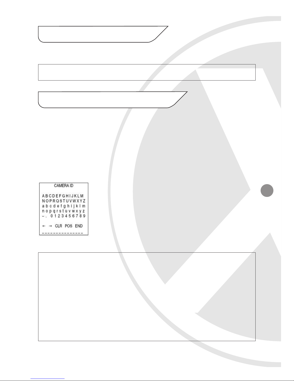
1 CAMERA ID
<Option: OFF / ON>
Display a name and/or number on the monitor,
to add a camera title
UP, DOWN, LEFT, RIGHT menu control= Select a character, then press
(SETUP) MENU to accept it. The character is saved and the title
cursor at the bottom of the screen moves to the next position.
<-- --> = Go back or forward in the title name to make changes
CLR= Delete the entire name and start again
POS= Position the camera title on the screen. Press (SETUP) MENU
to confirm the position
END= Accept the new name.
11. SPECIAL Menu Functions
Page 10
10
11. SPECIAL Menu Functions (continued)
2 COLOUR
<Option: AUTO / ON>
AUTO= Automatically detect colour or black/white
ON= Full time colour mode
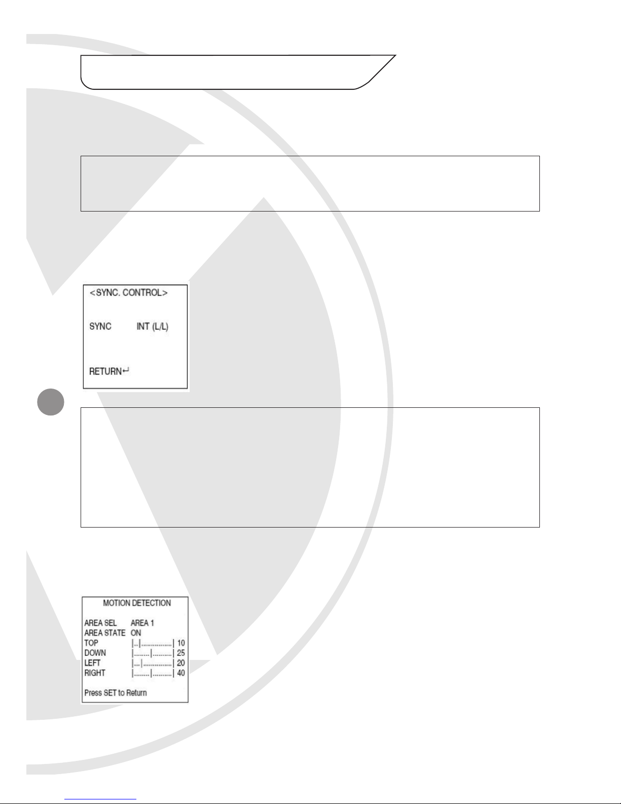
3 SYNC
<Option: INT / L/L>
INT = Synchronize the vertical interval sync pulse of
your camera with other equipment to reduce the
effect of picture roll on the monitor.
L/L (Line Lock) = Adjust the phase from 0° ~ 359°.
INTERNAL = When line lock is not required.
LINELOCK = Adjust the vertical phase (VPH) from 000 - 359 (factory
default is 0). Line line is only available with 24V AC
power.
RETURN = Press MENU to return to the SETUP menu.
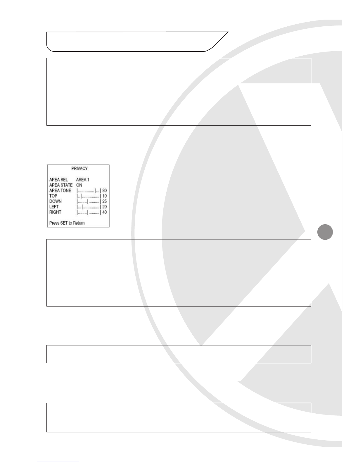
4 MOTION DET
<Option: OFF/ON>
Detect moving objects on screen; displays MOTION
DETECTED along with the number of movements
counted. Select the area on screen you want to
observe.
Page 11
11
11. SPECIAL Menu Functions (continued)
AREA SEL= Select a motion detection grid (top left, top right, bottom
left, bottom right) to modify.
AREA STATE= Activate or deactivate the selected grid.
TOP/DOWN/LEFT/RIGHT= Press LEFT or RIGHT menu control left or
right to alter the dimensions of the selected grid.
5 PRIVACY
<Option: OFF/ON>
Mask up to 4 areas of the screen from video
monitoring.
AREA SEL= Select a motion detection grid (top left, top right, bottom
left, bottom right) to modify.
AREA STATE= Activate or deactivate the selected grid.
TOP/DOWN/LEFT/RIGHT= Press LEFT or RIGHT menu control left or
right to alter the dimensions of the selected grid.
6 MIRROR
<Option: OFF/ON>
Produce a horizontal mirror image on screen.
7 SHARPNESS
<Option: OFF/ON>
Sharpen the image on screen.
Excessive sharpening may cause picture noise.
Page 12

12
11. SPECIAL Menu Functions (continued)
8 RESET
Restore all factory default settings.
9 RETURN
Return to the main SETUP menu.
Page 13

13
12. Specifications
Model: VIS600E
Picture Type: Day/Night
(B/W & Colour)
Image Sensor: Sony Ex View 1/3” CCD
DSP: Samsung DSP Chip &
Xvision X3 DSP Software
Resolution: 550TVL Colour
Lens Viewing Angle: 26 to 92°
Infra Red Nightvision: 60 metres
Minimum Illumination: 0 Lux (IR On) / 0.002 Lux
Audio: No
Operating Voltage: 12V DC 450mA
Suggested Power Supply: 12V DC 1250mA Regulated
Mounting: Wall/Ceiling
Weatherproofing: Yes
Dimensions (ØxD): 69mm x 131mm
Page 14

14
NOTES
Page 15

15
NOTES
Page 16

CCTV
Manufactured exclusively for:
Xvision (Europe) Group,
Head Office: London, U.K.
Email: [email protected]
Web: www.x-vision.co.uk
TECHNICAL SUPPORT:
For Technical Support for any Xvision product please contact your
local distributor.
LIMITED WARRANTY:
This product is supplied with a limited 3 Year warranty. The Warranty
excludes products that have been misused, (including accidental
damage) and damage caused by normal wear and tear. In the
unlikely event that you encounter a problem with this product, it
should be returned to the place of purchase.
16
 Loading...