

Page 1
1
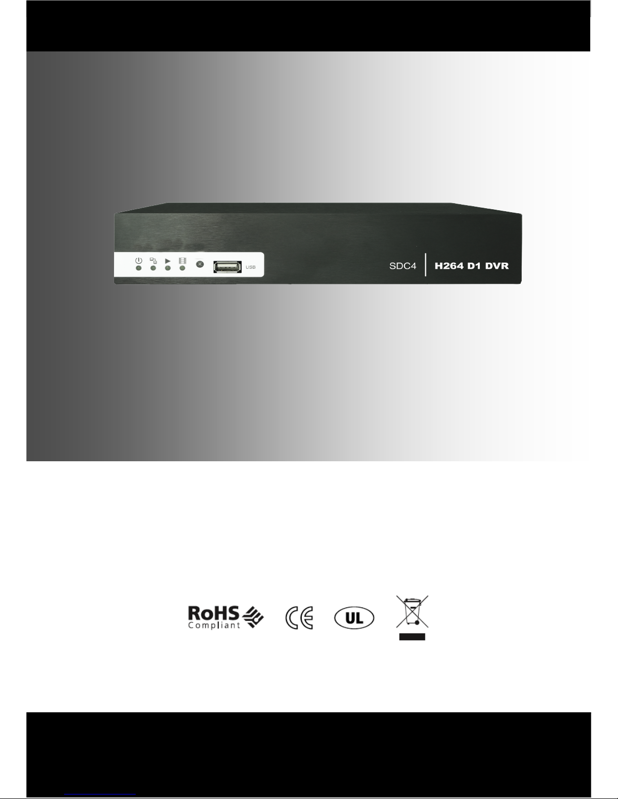
SDC4/SDC8
4/8 Camera DVR with Real Time D1 Resolution Recording
This document contains preliminary information and subject to change without notice.
QUICK GUIDE
Page 2

2
INDEX
1. Contents.................................................................................3
2. Hard Disk Installation............................................................4
3. Front Panel Controls.............................................................6
4. Rear Panel Connectors.........................................................7
5. Live Operations......................................................................9
6. Playback Operations............................................................11
7. PTZ Operations....................................................................13
Page 3

3
1. CONTENTS
1. DVR
2. Quick Start Guide
3. IR Remote Control
4. Battery
5. Installation CD
6. Screws
7. Power Adaptor
8. SATA Cable
Page 4
4
2. HARD DISK INSTALLATION
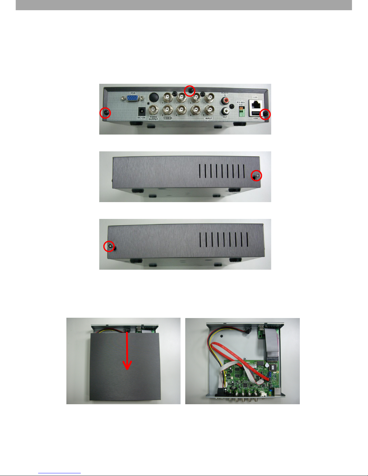
Step 1) Take out the screws as shown in the pictures below:
Back panel 3 screws
Left side 1 screw
Right side 1 screw
Step 2) Follow the direction of the arrow to open the cover.
Page 5
5
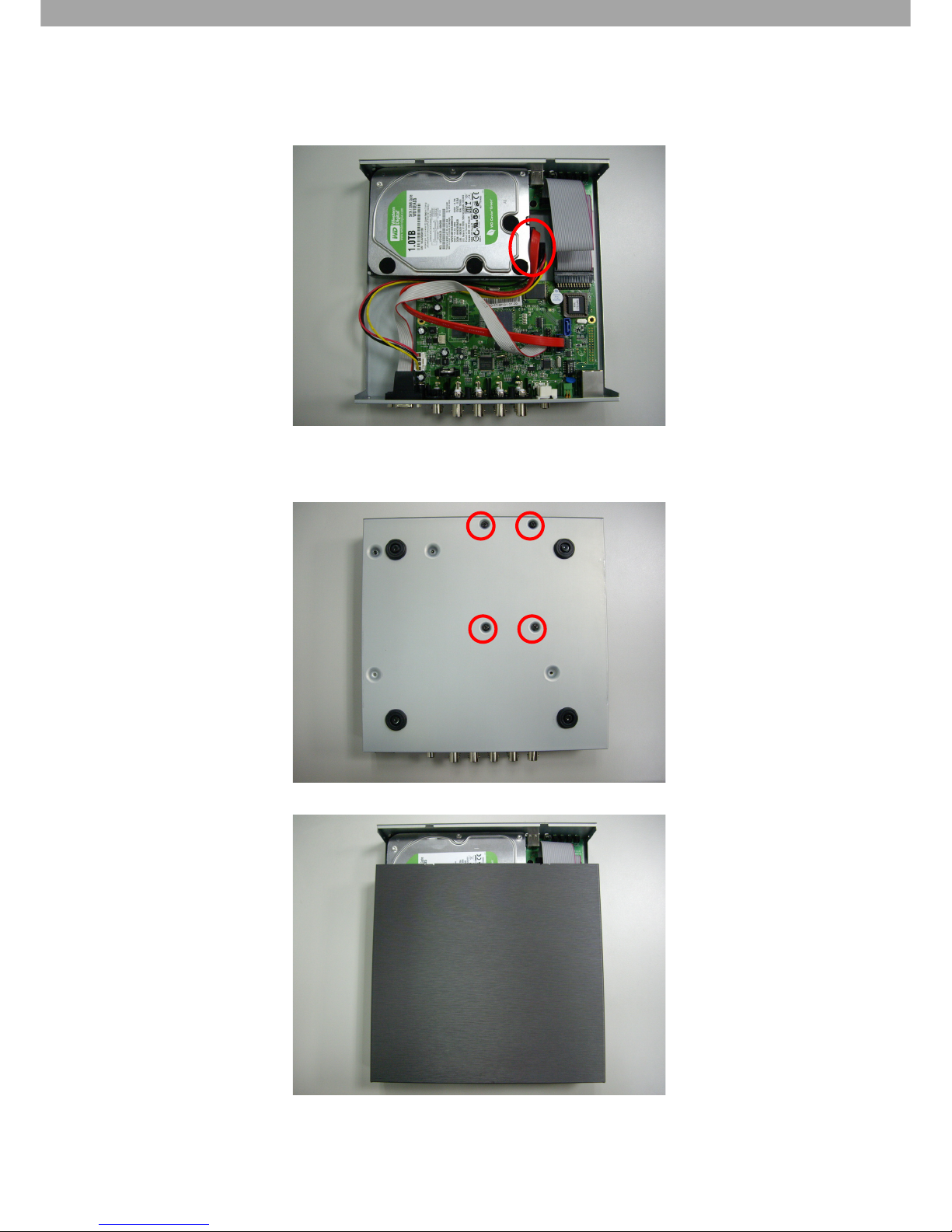
Step 3) Connect the SATA and power cables to the Hard Disk.
Step 4) Fix the Hard Disk with four screws on the bottom case as shown below
Step 5) Put the cover back and fix it with 5 screws as shown in Step 1.
Note: After installation, please format the Hard Disk before you start recording. For more
detailed information, please check the User Manual for reference.
Page 6
6
3. FRONT PANEL CONTROLS
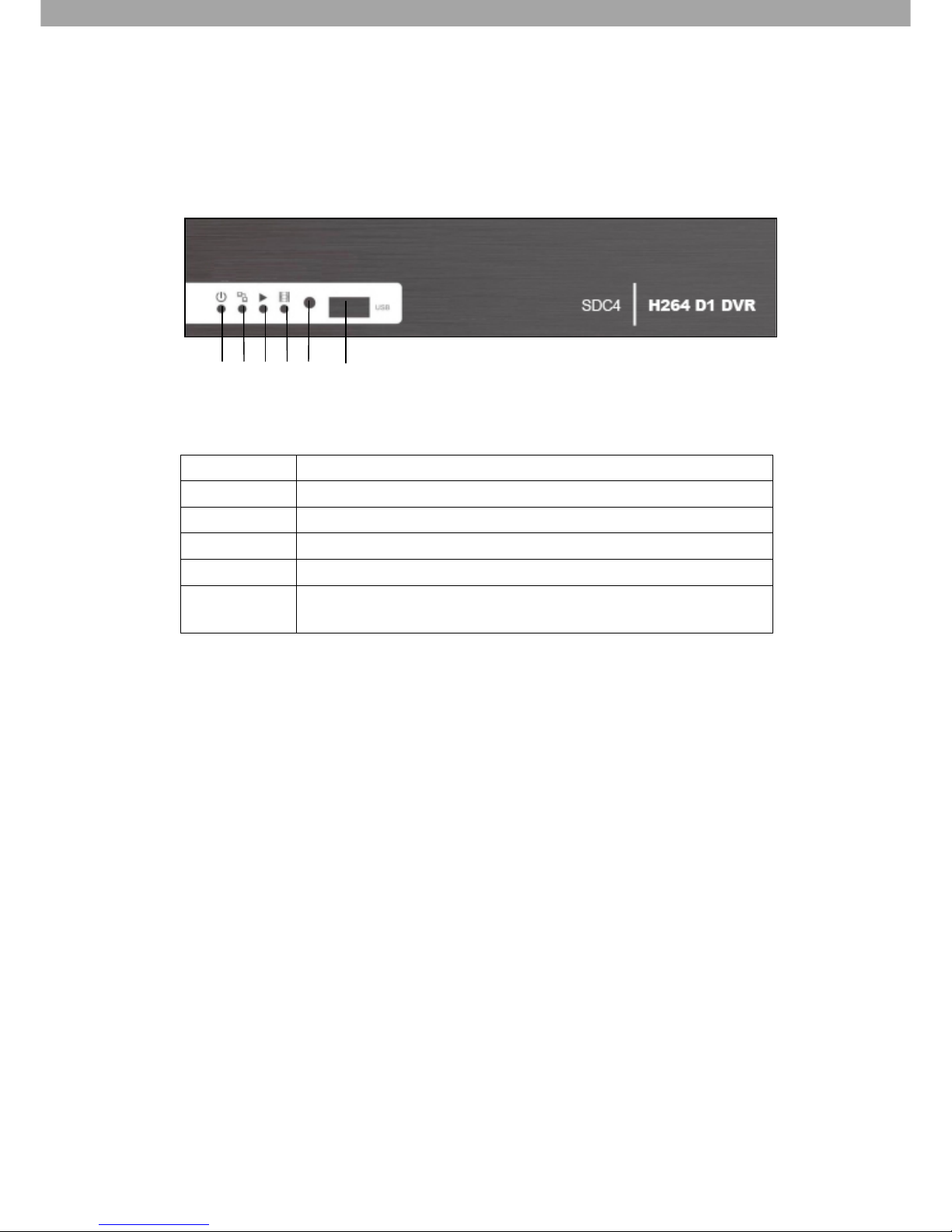
SDC4 (4 CHANNEL DVR) FRONT PANEL CONNECTORS
1. Power LED
Indicates DVR power is on.
2. LAN LED
Indicates LAN is working.
3. PLAY LED
Indicates DVR is playing back.
4. REC LED
Indicates DVR is recording.
5. IR Sensor
Remote control signal receiver.
6. USB port
USB port (For backing up onto USB Memory Stick or for mouse
connection).
1
2 3 4 5 6
Page 7
7
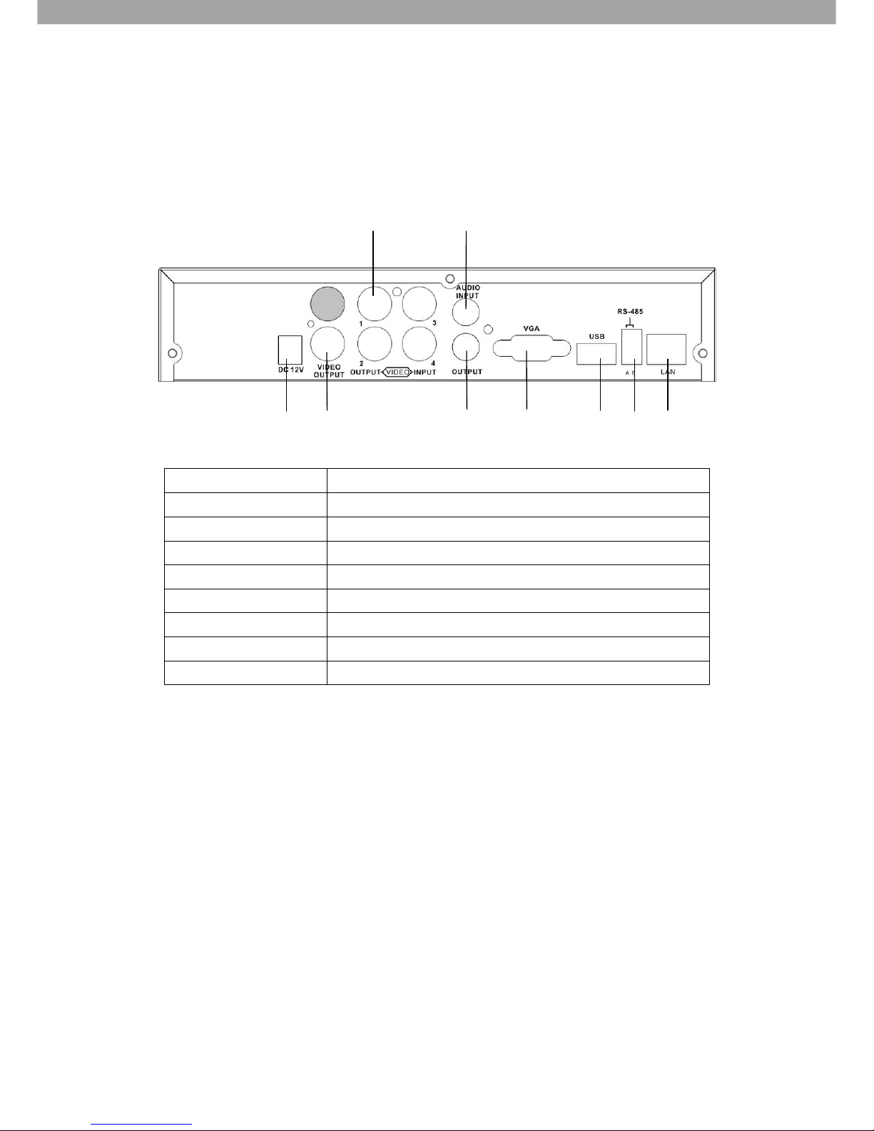
4. REAR PANEL CONNECTORS
SDC4 (4 CHANNEL DVR) REAR PANEL CONNECTORS
1. DC 12V
12V DC power jack.
2. VIDEO OUT
MAIN/SPOT monitor (BNC Video output).
3. VIDEO IN
Camera inputs (BNC Video input).
4. AUDIO IN
Phono input (For Channel 1).
5. AUDIO OUT
Phono output (For Channel 1).
6. VGA
VGA port.
7. USB
For mouse connection.
8. RS-485
RS485 for PTZ Control.
9. LAN
Network Ethernet port.
1 2 5 6 7 8 9
3 4
Page 8
8
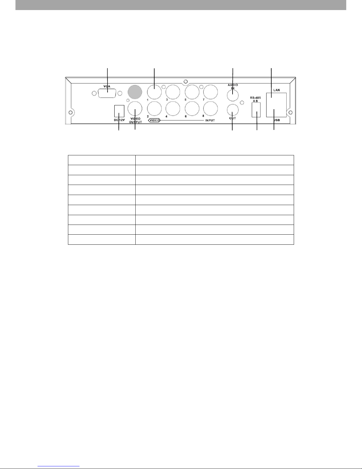
SDC8 (8 CHANNEL DVR) REAR PANEL CONNECTORS
1. VGA
VGA port.
2. 12V DC
12V DC power jack.
3. MAIN/SPOT monitor
MAIN/SPOT monitor (BNC Video output).
4. VIDEO IN
Camera inputs (BNC Video input).
5. AUDIO IN
Phono input (For Channel 1).
6. AUDIO OUT
Phono output (For Channel 1).
7. RS485
RS485 for PTZ Control.
8. LAN
Network Ethernet port.
9. USB 2.0
For mouse connection.
2 3 6 7 9
1 4
5 8
Page 9
9
5. LIVE OPERATIONS
You can monitor all the channels, listen to audio signal and have some related operations under
LIVE mode. This following describes the IR remote control, mouse operation and on-screen
graphical icons under LIVE mode.
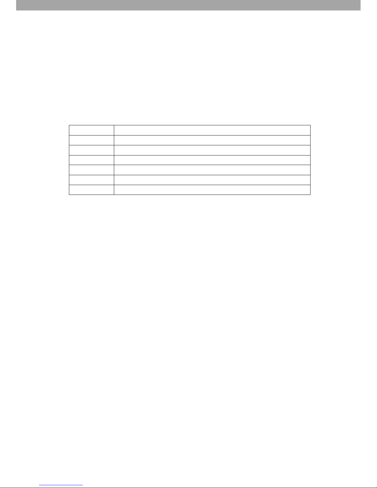
Table 5-1 Functions of remote control under LIVE mode
Button
Description
REC
Start/Stop recording.
PLAY
Start playing back the most recently recorded segment.
ENTER/MODE
Switch to full screen, quad display.
MENU/
Enable/ Disable setup Menu.
BK-UP
Enable/ Disable backup menu.
ESC
Return to previous menu.
Page 10
10
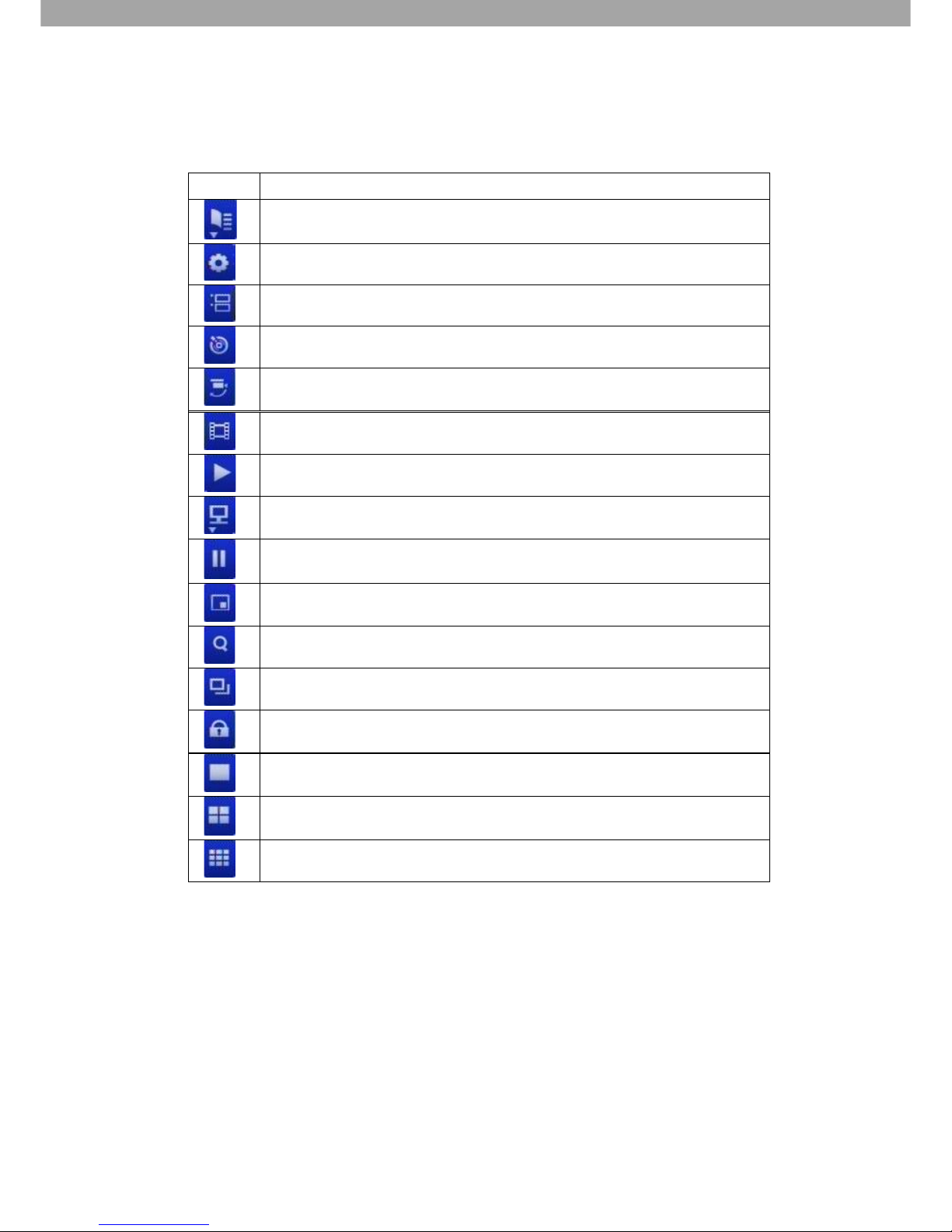
Table 5-2 Graphical icons displayed after right-clicking your mouse under LIVE mode.
Icon
Description
Resting the cursor on this icon will bring up the following four menu icons.
Main menu
Search menu
Backup menu
PTZ mode
Turn on/off recording
Playback
Resting the cursor on this icon will bring up the following five display icons.
FREEZE
PIP, picture in picture
ZOOM, double the screen size
AUTO-sequence
LOCK, Activate the key lock
Full screen display
Quad display
9 channel display
Page 11
11
6. PLAYBACK OPERATIONS
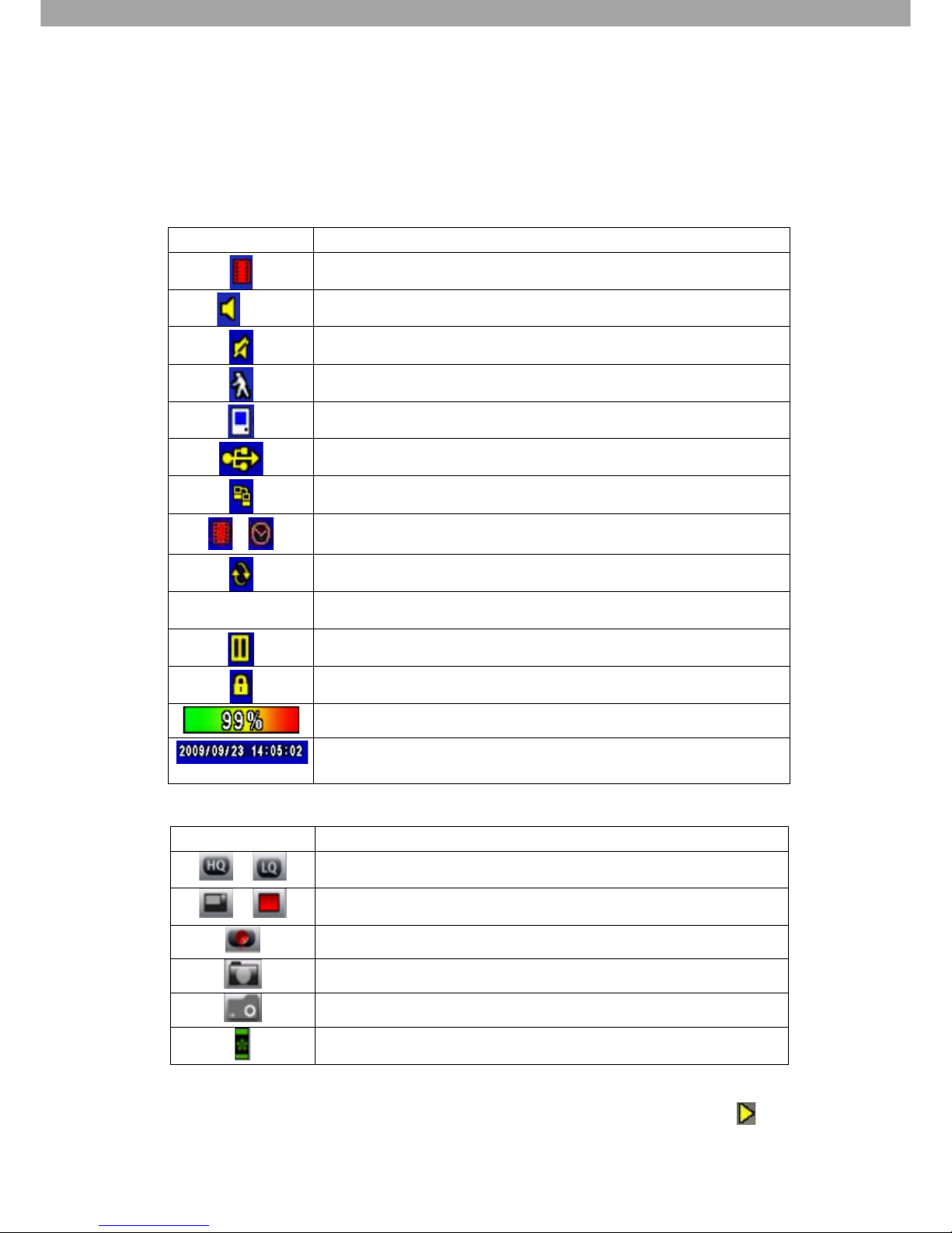
Table 6-1 Description of on-screen graphical icons in LIVE mode.
Icon
Description
Indicates Recording is on
1~4
Indicates Live Audio is on
Indicates Live Audio is off
Indicates Motion has been detected on the channel
Indicates Video loss has been detected on the channel
Indicates a USB device has been detected
Indicates the DVR is connected to the LAN
Film:Normal Recording
Clock:Schedule Recording
Indicates Auto-sequence is on
2X
Indicates 2X zoom is active
Indicates Screen is paused
Indicates DVR lock is on
Shows the current capacity of hard disk space used (99% used, 1% left)
Current time of recording is shown at the lower right corner of each
channel
Icon
Description
/
Click to switch Image quality (High/Low)
/
Click to toggle between Full screen mode (off/on)
Clink to Record
Click to take a Snapshot
Click to set the file saving path for recordings and snapshots
Click to Enable / Disable Shortcut Toolbar
Under LIVE mode, press PLAY to playback (the default setup is quad display).
The function icons will appear in the bottom right corner of the screen when this icon is
shown on the screen. Icons can be dragged with a mouse to other locations on the screen.
Page 12
12
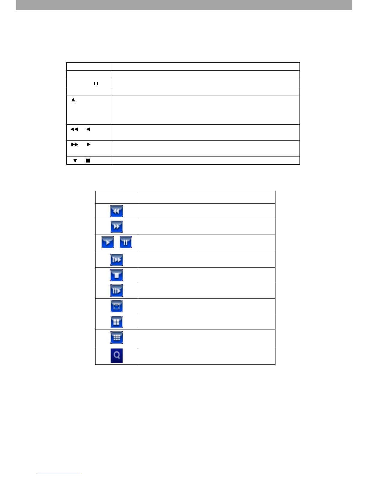
Table 6-2 Remote control functions under the PLAYBACK mode.
Icon
Description
ENTER/ MODE
Switch to full screen, quad display.
MENU /
Turn on/off PAUSE.
PLAY
Playback at normal speed.
/ SLOW
Playback at slower speed.
The speed will be slowed to 1/2, 1/4, 1/8, and 1/16 by each press of the
button till the slowest limitation of 1/16 of the normal speed.
Current playback speed is shown in the top right corner.
/
Fast rewind. Each press increases the speed to the next level.
There are six speeds: 2x, 4x, 8x, 16x, 32x and 64x.
/
Fast forward. Each press increases the speed to the next level.
There are six speeds: 2x, 4x, 8x, 16x, 32x and 64x.
/
Stop playback.
Table 6-3 Mouse operation under the PLAYBACK mode.
Icon
Description
Fast rewind.
Fast forward.
∕
Play/pause.
「▲ / SLOW」Slow playback.
「▼ / ■」Stop playback.
Playback frame by frame.
Full screen display.
Quad display.
9 channel display.
Zoom into display.
NOTE. If you wish to playback a single channel, double click the mouse button on the
channel’s video image.
Page 13
13
7. PTZ OPERATIONS
Under LIVE mode, press PTZ to enter PTZ camera mode. The function icons will appear in the
bottom right corner of the screen. Drag to other locations on the screen with the mouse.
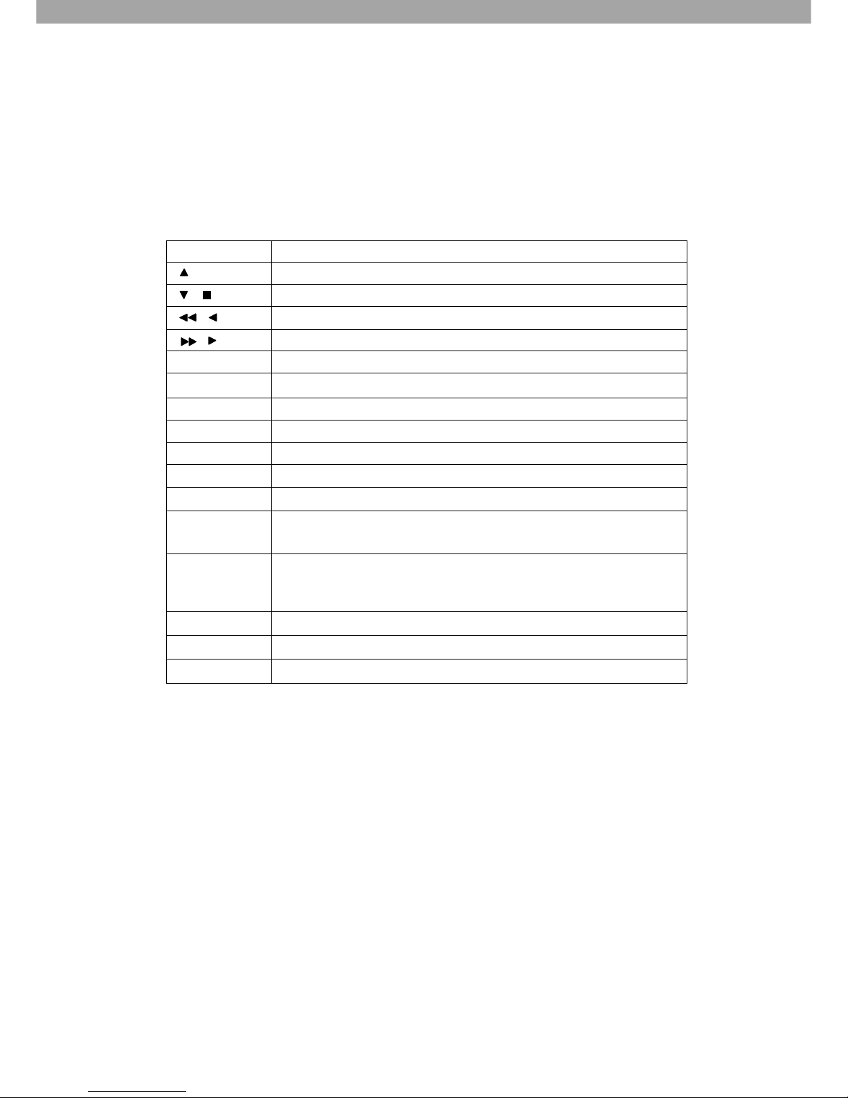
Table 7-1 Remote Control functions under the PTZ mode
Button
Description
/ SLOW
Move PTZ camera up.
/
Move PTZ camera down.
/
Move PTZ camera to the left.
/
Move PTZ camera to the right.
ZOOM +
Zoom in camera.
ZOOM -
Zoom out camera.
FOCUS +
Focus camera in.
FOCUS -
Focus camera out.
IRIS +
Open camera iris.
IRIS -
Close camera iris.
TOUR
Make the PTZ tour through pre-set locations in order*.
PRESET +
Number
Press the ‘PRESET’ key followed by a 2-digit number; the DVR
will set the current PTZ location to the number entered.
PLAY +
Number
Go to the Preset location. Press the ‘PLAY’ button first followed
by a 2-digit number; the PTZ camera will go to the correspondin
g preset number location.
PIP
Setup the first location for Auto Patrol*.
FREEZE
Auto patrol (in line scan)*.
ZOOM
Setup the last location for Auto Patrol*.
*PTZ communication protocols from different brands are NOT always 100% compatible.
Some of these functions may therefore be unavailable.
Page 14
14
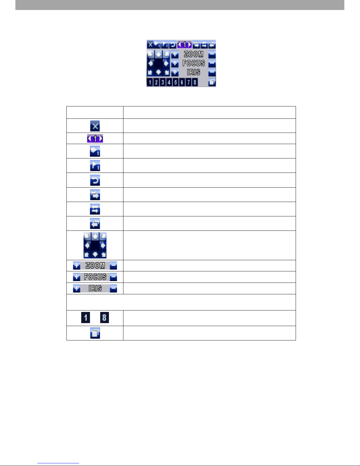
Table 7-2 Mouse operation under the PTZ mode
Icon
Description
Click to Exit PTZ Mode and go back to the LIVE mode.
Preset number N. (0-255).
Go to preset number N.
Set current PTZ location at preset number N.
TOUR - press to activate pre-set tour*.
PIP - Set current PTZ location as the start of tour scan*.
FREEZE - Activate tour scan*.
ZOOM - Set current PTZ location as the end of tour scan*.
Click arrows to move PTZ camera.
Zoom in / Zoom out.
PTZ focus in; PTZ focus out.
PTZ IRIS open, PTZ IRIS close.
The functions below need support from specific PTZ manufacturers. Please check the
User Manual of your PTZ camera for more detail.
to
AUX 1~8, AUTO Key + Number key (1~8).
Backup button.
*PTZ communication protocols from different brands are NOT always 100% compatible.
Some of these functions may therefore be unavailable.
 Loading...