


• Please unpack the box carefully and identify that all the parts are
present.
• Do not open the camera housing. This will void the warranty and
break the warranty seal inside the camera.
• Make sure you use only the recommended power supply. Damage
caused to the camera by incorrect voltage or wiring is not covered
by the warranty.
Model: PCC435
Colour Digital CCD
560x Zoom Camera
CCTV
Model:
PCC435
Colour Digital CCD
560x Zoom Camera
Before you begin

2
CONTENTS
1. SAFETY PRECAUTIONS........................................................................................................3
2. INTRODUCTION......................................................................................................................4
3. FEATURES.................................................................................................................................5
4. ACCESSORIES..........................................................................................................................6
5 NAME and FUNCTION of EACH PART................................................................................7
6. INSTALLATION......................................................................................................................10
6.1 Native Keyboard Installation ...............................................................................................11
6.2 PELCO Keyboard (or compatible) Installation....................................................................11
7. OPERATING PROCEDURE..................................................................................................12
7.1 Native Keyboard Operation .................................................................................................12
7.2 PELCO Keyboard (or compatible) Operation......................................................................13
8. SYSTEM SETUP .....................................................................................................................15
8.1 OSD (On Screen Display) FORMAT...................................................................................15
8.2 MENU DESCRIPTIONS.....................................................................................................18
8.3 SUB MENU DESCRIPTIONS............................................................................................19
9. Camera Control Command Protocol.....................................................................................26
9.1 Communication Format .......................................................................................................26
9.2 PC Command.......................................................................................................................27
9.3 Key Code Table....................................................................................................................58
10. SPECIFICATIONS................................................................................................................60
The author assumes no responsibility for any errors or omissions that may appear in this
document nor does the author make a commitment to update the information herein.
VER.:1.0, P/N.: R040158

W
ARNING: This symbol is intended to alert the user to the presence of un-insulated “dangerous
voltage”.
CAUTION: This symbol is intended to alert the user to presence of important operating and
maintenance (Servicing) instructions in the literature accompanying the appliance.
Disposal of Old Electrical & Electronic Equipment (Applicable in the European Union and other
European countries with separate collection systems).
This symbol on the product or on its packaging indicates that this product shall not be treated as
household waste. By ensuring this product is disposed of correctly, you will help prevent potential
negative consequences for the environment and human health, which could otherwise be caused by
inappropriate waste handling of this product. The recycling of materials will help to conserve natural
resources. For more detailed information about recycling of this product, please contact your local city
office, your household waste disposal service or the shop where you purchased the product.
Do not touch the zoom lens directly with your hands or fingers. Clean the zoom lens using soft cloth
moistened with alcohol to wipe off any dust.
Please be extra careful not to shake the product and avoid places where frequent vibrations or shocks
may occur.
Do not install the product in extreme temperature conditions.
Only use the camera under conditions where temperatures are between -10‡ and +50°.
Do not install the product in an environment where the humidity is high.
Do not spill liquid of any kind on the pr
oduct.
If it gets wet, wipe it dry immediately. Alcohol or beverage can contain minerals that corrode the electronic
components.
When minimum brightness of 0.01 Lux cannot be achieved during the night, please install appropriate
light fixtures.
If any abnormal operation or
accident occurs,. disconnect the device and contact your
dealer or the
near
est service center
.
Do not simultaneously connect to the DC 12V IN Jack (from the power source connector) and the DC 12V IN
(from the 6-pin Mini-DIN connector), as error may occur.
3
1. SAFETY PRECAUTIONS
C AUT IO N :
TO REDUCE THE RISK OF ELECTRICALSHOCK,
DO NOT OPEN COVERS (OR BACK).
N
O USER SERVICEABLE PARTS INSIDE.
REFER SERVICING TO QUALIFIED
S
ERVICE PERSONNEL.
It is advised to read the Safety Precaution Guide through carefully before operating the product, to
prevent any possible danger.

The auto-focus camera is a compact CCTV camera designed for easy integration into
surveillance systems. The Camera's built-in 35x Optical zoom lens spells added user
convenience since there is no need for separate adjustment of the focal distance. Current
applications include highway traffic control, plus security surveillance in such locations as
elevators and parking lots.
The advanced DSP technology allows intelligent control for clearer, detailed pictures.
Additionally
, the user can perform remote Zoom/ Focus/ Iris/ White Balance operations via
either RS-422/RS-485 or RS-232 (optional) interface. In combination with a highly sensitive
Sony 1/4” Ex View CCD sensor, these features make the auto-focus camera is particularly
suitable for surveillance.
Built-in Optical Zoom Lens with Digital Zoom
The built-in 35x optical zoom lens is highly reliable and offers auto focus and auto iris
functions. The camera also includes 16x digital zoom for a maximum of 560x combined
optical and digital zoom.
Day & Night
ICR function provides change from color to B/ W mode automatically or manually for
day and night 24-hour surveillance. Perfect use for Bank, Treasury, ATM, Road Station,
Port, Square, Warehouse, and etc. The chassis is equipped with IR cut filter change
mechanism. When Day & Night mode is set to "AE" on the OSD menu of the camera, the
camera will turn the IR Cut Filter according to exposure of the object. When the Day &
Night mode is set to "Sensor" on the OSD menu of the camera, the camera will turn the
IR Cut Filter according to the sensitivity of the SENSOR.
High Resolution
The chassis is equipped with a high sensitivity, high-resolution 1/4“ CCD pickup
featuring approximately 380,000 effective pixels. Thanks to a high 550 TVLhorizontal
resolution, picked-up images are reproduced with detail and clarity.
Setup Menu Function via Keys
Pushing keys on the rear panel of the camera can set each setup menu function. Setup
menu functions are displayed on screen display (OSD).
Camera Contr
ol via either RS-422/RS-485 or RS-232 (optional) interface
Camera control can adjust the camera's zoom, focus, Iris and white balance via either RS422/RS-485 or RS-232 (optional) interface.
Built-in Wire Remote Control Interface including Wet Contact and A/D Key
W
et contact interface is to control zooming and focusing. There are Menu, Tele, Wide,
Near
, Far and On/Of
f signals via
A/D key control.
The
A/D Key control signal can be
sent from
W
ire Remote Controller (optional).
Built-in Pan Tilt Zoom (PTZ) Protocols
The camera automatically recognizes four protocols, such as native protocol, PELCO (D
and P protocol) and LG protocol. Camera parameters can easily be setup via native
keyboard (RS-485) or PELCO keyboard (RS-422).
2. INTRODUCTION
4

1/4’’High Resolution Color CCD Camera.
Supports powerful function: Auto Iris Control (AIC), Auto White Balance (AWB), Auto
Gain Control (AGC), Auto Back Light Compensation (ABLC), Flickerless (FL) and Auto
Focus (AF).
35x Optical Zoom Lens and 16x Digital Zoom. (Total 560x Zoom).
Day & Night time vision (with IR Cut Filter change mechanism) including Day / Night
Control Interface.
On Screen Display (OSD) Setup Menu.
Camera Control via either RS-422/RS-485 or RS-232.
Supports PELCO (D and P)/ LG Protocol.
W
ire Remote Control (6 Pin Circular Connector) including wet contact interface to
control zooming and focusing and A/D Key Control for Menu, Tele, Wide, Near, Far and
On/Off signals.
Built-in 5 keys to Control Zooming and Focusing Function, and Setup Menu adjustment.
Built-in Audio.
3. FEATURES
5

6
4. ACCESSORIES
• Mounting Block ×1 and Screws ×2
• User’s Manual ×1
• Wire Remote Control Interface Cable ×1
• Wire Remote Controller (optional)
7
Focus (+ : Far , - : Near )
COM
DC12V IN
Zoom (+ : Tele , - : Wide)
GND
A/D KEY
REMOTE
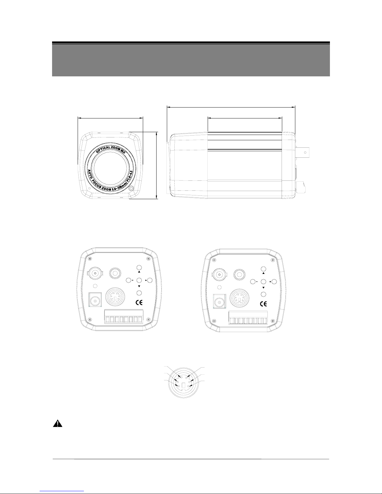
5 NAME and FUNCTION of EACH PART
Front View Side View
Figure 5-1 Figure 5-2
Rear View
Figure 5-3 Figure 5-4
Figure 5-5
CAUTION: Do not simultaneously connect to the DC 12V IN Jack (from the power source
connector) and the DC 12V IN (from the 6-pin Mini-DIN connector), as error
may occur.
126.1 mm ±0.5 mm
73 mm ±0.5 mm64 mm ±0.5 mm
65.5 mm ±0.5 mm
GND
DNO
GND
RD
GND
DNI
GND
TD
DC 12V IN
REMOTE
FAR
AUDIO
VIDEO
WIDE
NEARMENU
TELE
GND
DNO
T+
R+
DNI
GND
T-
R-
REMOTE
DC 12V IN
WIDE
FAR MENU NEAR
AUDIO
VIDEO
TELE

8
(1). Power Input:DC 12V ±10% (Recommendation 12V ±0.5V) Max 4.1W.
(2). Video Output:Composite Video 1Vp-p, 75 Ohms, BNC
(3). Audio Output:2Vp-p, 50 Ohms
(4). 5 Keys Control:
Name Function
Tele/S Zoom Tele or Up (S)
Wide/T Zoom Wide or Down (T)
Near/+ Focus Near or Increase (+)
Far/- Focus Far or Decrease (-)
Menu Enter or Exit Setup Menu
(5). Remote Control Interface (6 Pin Circular Connector):refer to figure 5-5
Name I/O Note
Zoom (+: T ele, -: Wide) Input ±6V (+3V~+13V, -3V~-13V)
Focus (+: Far,-: Near) Input ±6V (+3V~+13V, -3V~-13V)
COM Pair Ground for Zoom, Focus
A/D Key Input A/D (Voltage Divide) Control
GND Pair Ground for Power Supply and A/D Key
DC 12V IN Input Power Supply DC 12V ±10% (Recommendation 12V ±0.5V)
There are Menu, Tele, Wide, Near, Far and On/ Off signals via A/ D key.
(6). Camera Control:2.4K/ 4.8K/ 9.6K/ 19.2K BPS (Please refer to OSD setup MENU).
Optional: RS-422/ RS-485, refer to figure 5-3
Name Function
R+, R-, T+, T- Use For RS-422/RS-485 Control
Optional: RS-232, refer to figure 5-4
Name Function
RD, TD, GND Use for RS-232 Control
(7). Day & Night Control:refer to figure 5-3 or 5-4
Name Function
5V / 10mA: IR LED ON (NIGHT)
DAY&NIGHT OUTPUT (DNO)
0V: IR LED OFF (DAY)
Open Contact: DAY
DAY&NIGHT EXTERNAL INPUT (DNI)
Close Contact (Close to GND): NIGHT

9
Refer to Remote
Control Interface
DC 12V IN
TELE
FAR NEAR
MENU
WIDE
ON/ OFF
90.3 0.5mm
65 0.5mm
150 20mm
3000 120mm
Day & Night Output
This function will turn on the external IR LED lamp according to the position of IR cut filter .
Day & Night Output
5V / 10mA: IR LED ON (NIGHT)
0V: IR LED OFF (DAY)
Day & Night External Input
When Day & Night mode is set to "External" on the OSD menu of the camera, this
function will be switched to DAY mode or NIGHT mode according to the Day & Night
signal from the external light sensor or the IR LED lamp.
Day & Night External Input
Open Contact: DAY
Close Contact (Close to GND): NIGHT
(8). Wire Remote Controller (optional):30 meter cable, refer to figure 5-6, 5-7, 5-8
Button Name Function
Tele/S Zoom Tele or Up (S)
Wide/T Zoom Wide or Down (T)
Near/+ Focus Near or Increase (+)
Far/- Focus Far or Decrease (-)
Menu Enter or Exit Setup Menu
ON/OFF Power On/Off
Figure 5-6

10
6. INSTALLATION
TD
RD
GND
1
2
3
4
5
6
7
8
9
1 Frame GND
2 RD
3 TD
4 DTR
5 Signal GND
6 DSR
7 RTS
8 CTS
9 RI
Camera
RS-232 Interface
RS-232 D-Sub Connector
Figure 6-1
R+
T-
T+
R-
R+
R-
T+
T-
Camera
RS-422 Interface
RS-232 to RS-422 Converter
RD
TD
To PC or
Controller
Figure 6-2
R+
T-
T+
R-
D+
D-
Camera
RS-485 Interface
RS-232 to RS-485 Converter
RD
TD
To PC or
Controller
D-
D+
Figure 6-3

11
6.1 Native Keyboard Installation
RS-485 interface is used for communicating native keyboard. Refer to Figure 6-3;
connect R+ and T+ of the camera together; connect R+ and T+ of the camera to D+ of
the native keyboard. Connect R- and T- of the camera together; connect R- and T- of the
camera to D- of the native keyboard.
User could adjust Camera ID via rear panel keys or via remote commands. Protocol,
Speed and Parity should only be adjusted via rear panel keys.
Communication Setting
CAMERA ID 1 ~ 127
PROTOCOL AUTO, NATIVE
SPEED 9600
PARITY NONE
The speed of native keyboard is fixed (9600).
Adjusted function is only effective, after exiting the OSD setup menu.
6.2 PELCO Keyboard (or compatible) Installation
RS-422 interface is used for communicating PELCO keyboard. Refer to Figure 6-2;
connect R+ of the camera to T+ of the PELCO keyboard. Connect R- of the camera to
T- of the PELCO keyboard.
User could adjust Camera ID via rear panel keys or via remote commands. Protocol,
Speed and Parity should only be adjusted via rear panel keys.
Communication Setting
0 ~ 253 for P protocol
CAMERA ID
1 ~ 255 for D protocol
PROTOCOL AUTO, PELCO
SPEED 2400, 4800, 9600, 19200
PARITY NONE
The speed of camera should be the same as the speed of the keyboard.
Adjusted function is only effective, after exiting the OSD setup menu.
NOTE: Maximum cable distance for RS-422/ RS-485 communication over 24-gauge wire is
4,000 feet (1,219 m). Recommend using shielded twisted pair cable that meets the basic
requirements for EIA RS-422 / RS-485 applications.

12
7. OPERATING PROCEDURE
(1) Mount the camera on the mounting bracket by using the hole on the top or bottom of
the camera or by using the enclosed 8mm mounting block, furnished by 2 screws.
(2) Connect the Video Output to the monitor or other video device via a 75 Ohms type
coaxial cable.
(3) Connect the power source, using the DC Jack (+12V DC in the jack center) or Remote
Control Interface (6 Pin Circular Connector). Do not simultaneously connect to the
DC 12V IN Jack (from the power source connector) and the DC 12V IN (from the
6-pin Mini-DIN connector), as error may occur.
(4) Wait a while for the camera to power on and the zoom lens will resume to the previous
power on position automatically.
(5) Once the picture appears on the monitor, press the Zoom Tele, Zoom Wide, Focus
Near, Focus Far and Setup Menu Key to obtain the best picture quality.
7.1 Native Keyboard Operation
Normal Display Mode
Native Keyboard Camera Function
BRIGHTNESS+ Brightness +
BRIGHTNESS- Brightness -
NEAR Focus Near
FAR Focus Far
Zoom TELE Zoom T ele
Zoom WIDE Zoom Wide
Move Joystick Left None
Move Joystick Right None
Move Joystick Up None
Move Joystick Down None
Camera Function Native Keyboard
Accessing Main Menu Press the MENU key
Call up the Preset Points
Enter preset number (1~128) and press GO
PRESET to put camera in preset position.
Setting the Preset Points
To program, position camera, enter desired
preset number (1~128), and press SET
PRESET .
AUTO FOCUS Control
Press the AUTO FOCUS Key, the LED of
the AUTO FOCUS lights up and press
AUTO FOCUS key again, to disable the
function.

13
OSD Setup Menu Mode
Native Keyboard Camera Function
e
Decrease (-)
f
Increase (+)
c
Cursor Up
d
Cursor Down
BRIGHTNESS+ None
BRIGHTNESS- None
NEAR None
FAR None
Zoom TELE None
Zoom WIDE None
Move Joystick Left None
Move Joystick Right None
Move Joystick Up None
Move Joystick Down None
Please refer to the native keyboard manual for more information.
7.2 PELCO Keyboard (or compatible) Operation
Normal Display Mode
PELCO Keyboard Camera Function
OPEN Brightness +
CLOSE Brightness -
NEAR Focus Near
FAR Focus Far
Twist Joystick clockwise or Zoom In Zoom Tele
Twist Joystick counterclockwise or Zoom Out Zoom Wide
Move Joystick Left None
Move Joystick Right None
Move Joystick Up None
Move Joystick Down None
Camera Function PELCO Keyboard
Accessing Main Menu
Enter 95; press on the PRESET button
(approximately five seconds) until the main
menu appears on the screen.
Call up the Preset Points
Enter preset number (1~32, 35~82) and press
PRESET to put the camera in preset position.
Setting the Preset Points
To program, position camera, enter desired
preset number (1~32,35~82), and press on the
PRESET button for two seconds.

14
OSD Setup Menu Mode
PELCO Keyboard Camera Function
OPEN Sub Menu Enter
CLOSE Sub Menu Exit
NEAR Cursor Up
FAR Cursor Down
Twist Joystick clockwise or Zoom In None
Twist Joystick counterclockwise or Zoom Out None
Move Joystick Left Decrease (-)
Move Joystick Right Increase (+)
Move Joystick Up Cursor Up
Move Joystick Down Cursor Down
Please refer to PELCO Keyboard (or compatible) manual for more information.

15
8. SYSTEM SETUP
8.1 OSD (On Screen Display) FORMAT
OSD DISPLAY POSITION
12 34
5-2
67
8
9
5-1
Figure 8-1

16
OSD DISPLAY DESCRIPTION
FUNCTION OSD Format DESCRIPTION
Non display Auto Mode
1 FOCUS MODE
b
Manual / Push Auto Mode
Non display Back Light OFF
2 BACK LIGHT
“BLC” display
BLC ON / Auto / Super BLC Mode
Non display
Normal Shutter
(NTSC: 1 / 60, PAL: 1 / 50)
“Ff” display
Flickerless Mode
3 SHUTTER SPEED
1 / 125
.
.
1 / 30,000
29 variable steps.
AWB AUTO White Balance
HUE The HUE control is valid (0 ~ 99).
IWB WB Preset for INDOOR
OWB WB Preset for OUTDOOR
MWB Manual WB Adjustment.
4 WBC MODE
PWB
Push Auto White Balance; turn this
mode ON, the white trace automatically.
Turn this mode OFF; Preserve the white
of final auto tracing action (Manual).
PROTOCOL
AUTO/ NATIVE/
PELCO/ LG
5-1
COMM
Setting string:
"BBBB, P, D, S"
After power-on, information on
PROTOCOL and COMM will be
displayed.
This information will remain on the
monitor for a short interval.
5-2 STAND-BY MODE STAND-BY
Indicate the camera stand-by during the
camera’ s power turning ON.
Dx560 Digital Zoom mode
6 ZOOM DISPLAY
X35 Optical Zoom mode
7 CAMERA ID
According to the identification number (000 ~ 255) for each
camera, multi-point control (via PC or keyboard) is valid.
8 USER TITLE STRING Maximum 10 user char string
9 BRIGHTNESS Brightness data

17
NOTE:
Setting string: "BBBB, P, D, S"
BBBB represent baud rate, it can be one of the following values:
2400, 4800, 9600, 19200
P represent parity, it can be one of the following values:
N (None), O (Odd), E (EVEN)
D represent data bits, it should be the following value:
8
S represent stop bit, it should be the following value:
1
For example, the following string specifies a baud rate of 9600, no parity, 8 data bits, and
1 stop bit:
9600, N, 8,1

18
8.2 MENU DESCRIPTIONS
MAIN MENU
MENU
FOCUS SET
AWB SET
AE SET
SPECIAL SET
F OSD DISP
DAY/NIGHT
COMMUNICAT
INITIAL SET
EXIT
st
st
st
st
st
st
st
ON
st
SET UP THE MENU
In order to display the Setup Menu on the screen, set the Menu command or
press key panel.
To select each item, by using the Zoom Tele and Zoom Wide command or using
the Up (S) and Down (T) key panel.
To change the data, by using the Focus Far and Focus Near command or by
using the Decrease (-) and Increase (+) key panel.
Figure 8-2

19
8.3 SUB MENU DESCRIPTIONS
FOCUS SET
FOCUS MODE SET:
This function is for focus mode setting.
Set the mode to Auto, Manual, or Push Auto.
FOCUS DISTANCE SET:
This function is for selection of minimum shooting distance.
Set the Focus Distance mode to 1cm, 10cm, 50cm, 1M, 1.5M, 3M, 5M or
10M.
ZOOM START SET:
This function is for selection of zoom start position.
Set the Zoom Start mode from x1 to x34.
ZOOM END SET:
This function is for selection of zoom end position.
Set the Zoom End mode from x560 to x2.
ZOOM SPEED SET:
This function is for selection of zoom speed.
Set the Zoom Speed to slow, normal or high.
ZOOM TRACKING MODE SET:
This function is for selection of zoom tracking mode.
Set the Zoom Tracking mode to Auto or Manual.
Zoom Tracking means focused zooming state.
INITIAL SET:
If initial mode set to ON, All FOCUS function is changed to the factory
setting.
RETURN TO MAIN MENU:
Exit the FOCUS set of OSD menu and return to the main menu.

20
AWB SET
WB MODE SET:
This function is for changing the WB mode.
Set the mode to Auto, Hue, Indoor, Outdoor, Manual, or Push Auto.
AUTO: WB color temperature range = 2500°K ~ 8000°K.
Manual WB: Adjust Red and Blue gain to perform a desired White Balance.
PUSH AUTO: Set the WB mode to Push Auto.
HUE CONTROL SET:
This function is valid for Hue WB mode.
Adjust the level from 0 MIN to 99 MAX.
RED GAIN SET:
This function is valid for Manual WB mode.
This mode is an optional adjustment function, for users to adjust special
colors.
BLUE GAIN SET:
This function is valid for Manual WB mode.
This mode is an optional adjustment function, for users to adjust special
colors.
PUSH AUTO SET:
This function is valid for Push Auto WB mode.
Turn this mode ON, the white trace automatically. Turn this mode OFF;
Preserve the white of final auto tracing action (Manual).
INITIAL SET:
If initial mode set to ON, All AWB function is changed to the factory setting.
RETURN TO MAIN MENU:
Exit the AWB set of OSD menu and return to the main menu.

21
AE SET
AE MODE SET:
This function is for changing the AE mode.
Set the mode to AUTO, IRIS MAN, AGC MAN, or Manual.
IRIS ADJUST SET:
This function is valid for IRIS MAN mode.
Adjust the level from 36 MIN to 250 MAX.
AGC MAXIMUM SET / AGC ADJUST SET:
This function is valid for AGC AUTO mode / AGC MAN mode.
AGC AUTO means AUTO or IRIS MAN.
Adjust the level from 28 MIN to 255 MAX.
BRIGHTNESS ADJUSTMENT SET:
Adjust the level from 0 MIN to 99 MAX.
BACKLIGHT SET:
Set the mode to OFF, ON, AUTO, or SUPER.
Back Light Compensation (BLC) is ON:
BLC could emphasize the luminance of the BLC Area according to the BLC
Level.
AUTO BLC:
When a back light condition occurs in area1, area2, area3, or area4. The back
light compensation is enabled automatically. When the back light condition
disappears in that area, BLC is disabled automatically. To disable this mode,
set it to OFF.
Area 1
Area 3 Area 4
Area 2
Are a 0
@ BLC area is Area 0.
SUPER BLC:
BLC could emphasize the luminance of the image according to the light
condition.

22
BLC LEVEL SET:
This function is valid for BLC ON mode.
Adjust the level from 0 MIN to 80 MAX.
BLC AREA SET :
This function is valid for BLC ON or AUTO BLC mode.
Define the main object area that is under exposure based on the average
luminance of the whole image.
Set the BLC area Center (area 0), Top Small (TopS) (area1+area2), Top Large
(TopL) (area1+area2+area0), Bottom Small (BottomS) (area3+area4), Bottom
Large (BottomL) (area3+area4+area0), Left (area1+area3) or Right
(area2+area4).
FLICKERLESS SET:
Select the mode ON or OFF. Use for preventing picture flicker.
In case of NTSC System, Shutter Speed is 1/100 sec.
In case of PAL System, Shutter Speed is 1/120 sec.
SHUTTER SPEED SET:
Set the mode Normal (NTSC: 1/60, PAL: 1/50), 1/125, 1/150, 1/200, 1/250,
1/300, 1/350, 1/400, 1/450, 1/500, 1/600, 1/700, 1/800, 1/900, 1/1000, 1/1100,
1/1200, 1/1300, 1/1500, 1/1600, 1/1800, 1/2000, 1/2500, 1/3000, 1/3500,
1/4000, 1/6000, 1/10000, 1/30000 sec.
INITIAL SET:
If initial mode set to ON, All AE function is changed to the factory setting.
RETURN TO MAIN MENU:
Exit the AE set of OSD menu and return to the main menu.

23
SPECIAL SET
USER TITLE SET:
This function is for setting up user title on screen display.
Set the position of title using Near / Far Command, set the data using Tele /
Wide Command.
SHARPNESS ADJUST Set:
Adjust the level from 0 to 15.
MIRROR Set:
Select the mode ON or OFF.
This function applies only to high resolution.
This function is only available when the Digital Zoom Mode is OFF.
NEGATIVE Set:
This mode is to change color and luminance to negative.
Select the mode ON or OFF.
WIDE BURST Set:
This mode is to change color burst width for long distance application.
Select the mode ON or OFF.
INITIAL SET:
If initial mode set to ON, All SPECIAL function is changed to the factory
setting.
RETURN TO MAIN MENU:
Exit the SPECIAL set of OSD menu and return to the main menu.

24
F. OSD SET
FUNCTION DISP ON or DISP OFF
There are Focus Mode, Back Light, Shutter Speed and WBC Mode in the
function display.
CAMERA ID DISP ON or DISP OFF
ZOOM MAG DISP ON or DISP OFF
USER TITLE DISP ON or DISP OFF
INIT TITLE DISP ON or DISP OFF
BRIGHTNESS DISP ON or DISP OFF
DAY/ NIGHT SET
DAY/ NIGHT MODE SET:
This function is used for Day & Night control mode setting.
Set the mode to AE Mode, SENSOR mode, Day mode, Night mode, or External
mode.
If manual IRIS or manual AGC is selected, you cannot set AE mode to Day &
Night control mode.
SENSOR LEVEL Set:
Adjust the level from 0 to 255.
The SENSOR level threshold is used for filter setting (setup result is reflected
according to the sensitivity of the SENSOR).
FILTER DLY Set:
Adjust the level from 1 to 15 seconds.
Delay time for turning the filter.
The function is valid to SENSOR mode.
INITIAL SET:
If initial mode set to ON, All DAY / NIGHT function is changed to the factory
setting.
RETURN TO MAIN MENU:
Exit the DAY/ NIGHT set of OSD menu and return to the main menu.

25
COMMUNICATION SET
Adjusted communication function is only effective, after exiting the OSD setup menu.
Protocol Set, Speed Set and Parity Set should only be adjusted via rear panel keys.
CAMERA ID
To connect numerous cameras, identification number is assigned to each camera
for camera control (000 ~ 255: total numbers of ID are 256). ID 1 ~ 127 for
native keyboard; ID 0 ~ 253 for PELCO P protocol; ID 1 ~ 255 for PELCO D
protocol.
PROTOCOL SET:
Set the mode to AUTO, NATIVE, PELCO or LG.
Camera automatically detects the type of PELCO Protocol. No extra settings are
required to set D and P Protocols.
SPEED SET:
Set the speed to 2400, 4800, 9600 or 19200.
PARITY SET:
Set the parity to NONE, ODD, or EVEN.
INITIAL SET
Set the initial set mode to ON, All functions are changed to the factory setting,
excluding communication function.
EXIT
Exit the OSD menu and enter the normal display.
Letters in BOLD: Default Mode.

26
9. Camera Control Command Protocol
(For RS-232, RS-422, and RS-485)
9.1 Communication Format
The communication data format from PC to Camera
Data of total 6 bytes is transmitted from PC to camera.
Format:
Byte1 Byte2 Byte3 Byte4 Byte5 Byte6
0xC5 Code1 Code2 Code3 CAM_ID C.S.
Description: (Refer to 9.2 PC Command)
(a) Byte 1: Camera realizes the protocol comes from the PC.
(b) Byte 2: The data is changeable according to the PC Command.
(c) Byte 3: The data is changeable according to the PC Command.
(d) Byte 4: The data is changeable according to the PC Command.
(e) Byte 5: Camera’s ID (Identification) number to communicate (0 ~ 255).
It will be impossible to communicate when there’s a difference between the
value of CAM_ID and the given value of the Camera’s ID.
(f) Byte 6: The value of Check Sum from ‘Byte 1’ to ‘Byte 5’.
Ex.: In case of transmission, ‘0xC5, 0x5F, 0x0C, 0x00, 0x00‘
0xC5 + 0x5F + 0x0C + 0x00 + 0x00 = 0x130
Therefore, C.S. = 0x30

27
The communication data format from Camera to PC
Data of total 9 bytes is transmitted from Camera to PC.
Format:
Byte1 Byte2 Byte3 Byte4 Byte5 Byte6 Byte7 Byte8 Byte9
0xC5 Code1 Code2 Code3 Data1 Data2 Data3 Data4 C.S.
Description: (Refer to 9.2 PC Command)
(a) Byte 1: Camera is realized the protocol comes from PC.
(b) Byte 2: Byte 1 data is received from PC.
(c) Byte 3: Byte 2 data is received from PC.
(d) Byte 4: Byte 3 data is received from PC.
(e) Byte 5: The data is changeable according to the PC Command.
(f) Byte 6: The data is changeable according to the PC Command.
(g) Byte 7: The data is changeable according to the PC Command.
(h) Byte 8: The data is changeable according to the PC Command.
(i) Byte 9: The value of Check Sum from ‘Byte 1’ to ‘Byte 8’.
The computing method is the same as “Byte6 of the communication from PC
to Camera“.
9.2 PC Command
Exposure Mode Setting
Set the mode of Exposure according to AEmodeCNT.
PC → Camera
0xC5 0xAA 0x60 AEmodeCNT CAM_ID C.S.
Camera → PC
0xC5 0xAA 0x60 AEmodeCNT 0x60 0xXX 0xXX 0xXX C.S.
AEmodeCNT: The counter for setting Exposure Mode
1. In case of AEmodeCNT = 0x00, the Exposure Mode becomes “AUTO” mode.
2. In case of AEmodeCNT = 0x01, this value is not used.
3. In case of AEmodeCNT = 0x02, the Exposure Mode becomes “IRIS MAN” mode. And then
you can adjust “IRIS level” manually.
4. In case of AEmodeCNT = 0x03, the Exposure Mode becomes “AGC MAN” mode. And you can
adjust “AGC level” manually.
5. In case of AEmodeCNT = 0x04, the Exposure Mode becomes “MANUAL” mode. And you can
adjust “IRIS level” and “AGC level” manually.
6. In case of AEmodeCNT = every other value, the Exposure Mode remains changed.

28
BACKLIGHT Level Read
Read the current BACKLIGHT level of Camera.
PC → Camera
0xC5 0xAA 0x61 0x00 CAM_ID C.S.
Camera → PC
0xC5 0xAA 0x61 0x00 BL_level 0xXX 0xXX 0xXX C.S.
BL_level: This is a value of the camera for controlling BACKLIGHT level.
Adjust BACKLIGHT level
Adjust current BACKLIGHT level of Camera.
PC → Camera
0xC5 0xAA 0x62 BL_level CAM_ID C.S.
Camera → PC
0xC5 0xAA 0x62 BL_level 0x62 0xXX 0xXX 0xXX C.S.
BL_level: This is a value to adjust BACKLIGHT level of camera.
White Balance Mode Setting
Set the mode of White Balance according to WB_CNT.
PC → Camera
0xC5 0xAA 0x65 WB_CNT CAM_ID C.S.
Camera → PC
0xC5 0xAA 0x65 WB_CNT 0x65 0xXX 0xXX 0xXX C.S.
WB_CNT: This is an index counter to change the mode of White Balance
1. In case of WB_CNT = 0, the mode of White Balance becomes “AUTO” mode.
2. In case of WB_CNT = 1, the mode of White Balance becomes “HUE” mode.
3. In case of WB_CNT = 2, the mode of White Balance becomes “INDOOR” mode.
4. In case of WB_CNT = 3, the mode of White Balance becomes “OUTDOOR” mode.
5. In case of WB_CNT = 4, the mode of White Balance becomes “MANUAL” mode.
6. In case of WB_CNT = 5, the mode of White Balance becomes “PUSH AUTO” mode.
7. In case of WB_CNT = every other value, the mode of White Balance remains unchanged.

29
Camera ID Display Mode ON/OFF Toggle control
Switch the display mode of camera ID (ON/OFF).
PC → Camera
0xC5 0xAA 0x6A 0x00 CAM_ID C.S.
Camera → PC
0xC5 0xAA 0x6A 0x00 0x6A 0xXX 0xXX 0xXX C.S.
Caution: If the Camera ID is “OFF” mode, then the Camera ID is not displayed.
Zoom Lens Position Read
Read the current position value of Zoom lens & Digital Zoom MAG data.
PC → Camera
0xC5 0x36 0x00 0x00 CAM_ID C.S.
Camera → PC
0xC5 0x36 0x00 0x00 ZP_CNT+1 ZP_CNT V_MAG 0xXX C.S.
1. ZP_CNT+1: Upper byte of Zoom lens position.
2. ZP_CNT: Lower byte of Zoom lens position.
3. V_MAG: Digital zoom data.
Ex. In case of Zoom lens Position = 0x12A & Digital zoom data = 0x10,
a. ZP_CNT+1 = 0x01
b. ZP_CNT = 0x2A
c. V_MAG = 0x10
Caution: This command is used to set the PRESET mode control.
Focus Lens Position Read
Read the current value of Focus lens.
PC → Camera
0xC5 0x37 0x00 0x00 CAM_ID C.S.

30
Camera → PC
0xC5 0x37 0x00 0x00 FP_CNT+1 FP_CNT 0xXX 0xXX C.S.
1. FP_CNT+1: Upper byte of Focus lens position.
2. FP_CNT: Lower byte of Focus lens position.
Ex. In case of Focus lens Position = 0x1A2,
a. FP_CNT+1 = 0x01
b. FP_CNT = 0xA2
Caution: This command is used to set the PRESET mode.
Camera Power ON
Turn on the power of Camera.
PC → Camera
0xC5 0x3A 0x00 0x00 CAM_ID C.S.
Camera → PC
0xC5 0x3A 0x00 0x00 0x00 0x00 0xXX 0xXX C.S.
Camera Power OFF
Turn off the power of Camera.
PC → Camera
0xC5 0x3E 0x00 0x00 CAM_ID C.S.
Camera → PC
0xC5 0x3E 0x00 0x00 0x00 0x00 0xXX 0xXX C.S.
Memorize Zoom Lens Position for External PRESET control
Memorize the Zoom lens position into the volatile “Buffer RAM” designated “Buffer
RAM Index” for the external PRESET Move control.
PC → Camera
0xC5 0x49 PRE_I_ZH ZPL CAM_ID C.S.
Camera → PC
0xC5 0x49 PRE_I_ZH ZPL PRE_I_ZH 0xXX 0xXX 0xXX C.S.

31
1. PRE_I_ZH: The index value of the Buffer RAM to store the position of the Zoom lens for
the PRESET mode, and the upper data of position value for the Zoom lens.
Bit No. Bit 7 Bit 6 Bit 5 Bit 4 Bit 3 Bit 2 Bit 1 Bit 0
Description Buffer RAM Index (0 ~ 7) Upper data of Zoom lens position
2. ZPL: Lower data of position value for the Zoom lens.
Ex. The position of Zoom Lens to memorize = 0x126 &
The index of Buffer RAM for PRESET = 2
0xC5 0x49 PRE_I_ZH ZPL CAM_ID C.S.
0xC5 0x49 0x21 0x26 CAM_ID C.S.
Memorize Focus Lens Position for External PRESET control
Memorize the Focus lens position into the volatile “Buffer RAM” designated “Buffer
RAM Index” for the external PRESET Move control.
PC → Camera
0xC5 0x4A PRE_I_FH FPL CAM_ID C.S.
Camera → PC
0xC5 0x4A PRE_I_FH FPL PRE_I_FH 0xXX 0xXX 0xXX C.S.
1. PRE_I_FH: The index value of Buffer RAM to store the position of the Focus lens for the
PRESET mode, and the upper data of position value for the Focus lens.
Bit No. Bit 7 Bit 6 Bit 5 Bit 4 Bit 3 Bit 2 Bit 1 Bit 0
Description Buffer RAM Index (0 ~ 7) Upper data of Focus lens position
2. FPL: Lower data of position value for the Focus lens.
Ex. Memorize 0x21F to the Focus Lens Position in PRESET 3.
0xC5 0x4A PRE_I_FH FPL CAM_ID C.S.
0xC5 0x4A 0x32 0x1F CAM_ID C.S.
Memorize Digital Zoom Position for External PRESET control
Memorize the Digital Zoom position into the volatile “Buffer RAM” designated “Buffer
RAM Index” for the external PRESET Move control.
PC → Camera
0xC5 0x4B PRE_I DZP CAM_ID C.S.

32
Camera → PC
0xC5 0x4B PRE_I DZP PRE_I 0xXX 0xXX 0xXX C.S.
1. PRE_I: The index value of Buffer RAM to store the position of the Digital Zoom for the
PRESET mode.
Bit No. Bit 7 Bit 6 Bit 5 Bit 4 Bit 3 Bit 2 Bit 1 Bit 0
Description Buffer RAM Index (0 ~ 7)
2. DZP: Digital Zoom position.
Ex. Memorize 0x20 to the Digital Zoom Position in PRESET 0.
0xC5 0x4B PRE_I DZP CAM_ID C.S.
0xC5 0x4B 0x00 0x20 CAM_ID C.S.
Non Zoom Tracking External PRESET Move Control
Move the Zoom and Focus lens to each position and set the Digital Zoom ratio
according to data memorized in PRESET “Buffer RAM” designated ‘ INDEX’.
PC → Camera
0xC5 0x4D INDEX 0x00 CAM_ID C.S.
Camera → PC
0xC5 0x4D INDEX 0x00 INDEX 0xXX 0xXX 0xXX C.S.
INDEX: Position setting index of the PRESET Buffer RAM to change Zoom, Focus &
Digital Zoom position.
Caution: The range of INDEX is from 0x00 to 0x07.
Camera RESTART
Restart the Camera’s micro controller (u-COM).
PC → Camera
0xC5 0x4F 0x00 0x00 CAM_ID C.S.
Camera → PC
0xC5 0x4F 0x00 0x00 0x00 0xXX 0xXX 0xXX C.S.
Digital Zoom Power Adjust
Adjust Digital Zoom Max Power.
PC → Camera
0xC5 0x52 INDEX 0x00 CAM_ID C.S.

33
Camera → PC
0xC5 0x52 INDEX 0x00 INDEX 0xXX 0xXX 0xXX C.S.
INDEX: Index value for setting up Max Power Digital Zoom.
1. In case of INDEX = 0, the Max Power Digital Zoom = 2X. Therefore, Total Zoom = 70X.
2. In case of INDEX = 1, the Max Power Digital Zoom = 3X. Therefore, Total Zoom = 105X.
3. In case of INDEX = 2, the Max Power Digital Zoom = 4X. Therefore, Total Zoom = 140X.
4. In case of INDEX = 3, the Max Power Digital Zoom = 5X. Therefore, Total Zoom = 175X.
5. In case of INDEX = 4, the Max Power Digital Zoom = 6X, Therefore, Total Zoom = 210X.
6. In case of INDEX = 5, the Max Power Digital Zoom = 7X. Therefore, Total Zoom = 245X.
7. In case of INDEX = 6, the Max Power Digital Zoom = 8X. Therefore, Total Zoom = 280X.
8. In case of INDEX = 7, the Max Power Digital Zoom = 9X. Therefore, Total Zoom = 315X.
9. In case of INDEX = 8, the Max Power Digital Zoom = 10X. Therefore, Total Zoom = 350X.
10. In case of INDEX = 9, the Max Power Digital Zoom = 11X. Therefore, Total Zoom = 385X.
11. In case of INDEX = 10, the Max Power Digital Zoom = 12X. Therefore, Total Zoom = 420X.
12. In case of INDEX = 11, the Max Power Digital Zoom = 13X. Therefore, Total Zoom = 455X.
13. In case of INDEX = 12, the Max Power Digital Zoom = 14X. Therefore, Total Zoom = 490X.
14. In case of INDEX = 13, Max Power Digital Zoom = 15X. Therefore, Total Zoom = 525X.
15. In case of INDEX = 14, Max Power Digital Zoom = 16X. Therefore, Total Zoom = 560X.
16. In case of INDEX = every other value, the Max Power Digital Zoom remains unchanged.
Key Action
Perform the Key action according to the data of "KEY_NUM".
Caution: After using the Key action, Camera has to be notified by stop of key action
code KEY_NUM = “KN_STOP“.
PC → Camera
0xC5 0x5F KEY_NUM 0x00 CAM_ID C.S.
Camera → PC
0xC5 0x5F KEY_NUM 0x00 KEY_NUM 0xXX 0xXX 0xXX C.S.
KEY_NUM: This is a Key code value for operation (Refer to 9.3 Key Code Table).
Changing CAM ID
Change the data of CAM_ID to “NEW_C_ID“ and Camera ID mode.
PC → Camera
0xC5 0x78 NEW_C_ID On/Off CAM_ID C.S.

34
Camera → PC
0xC5 0x78 NEW_C_ID On/Off NEW_C_ID 0xXX 0xXX 0xXX C.S.
1. NEW_C_ID; New data to change Camera ID.
2. On/Off: Setting the Camera ID mode to “On” or “Off”.
If On/Off = “0x00”, the Camera ID mode becomes “OFF” mode. In this case, we
may ignore “CAM_ID” value. Otherwise, the Camera ID mode becomes “ON”
mode. Then, the value of CAM_ID is changed to “NEW_C_ID”.
CAM ID Read
Read the data of Camera ‘s ID.
Caution: This command may only be used in condition of one by one connection (PC vs.
CAMERA).
PC → Camera
0xC5 0xCC 0x00 0x00 CAM_ID C.S.
Camera → PC
0xC5 0xCC 0x00 0x00 CAM_ID On/Off 0xXX 0xXX C.S.
1. CAM_ID; The Camera ID data of a CAMERA.
2. On/Off: The On/Off mode of the camera ID.
0x00: Camera ID is “OFF” mode.
0xFF: Camera ID is “ON” mode.
Auto Back Light Mode ON/OFF control
Change the Auto Back Light Mode of camera.
PC → Camera
0xC5 0xAA 0x6D MODE CAM_ID C.S.
Camera → PC
0xC5 0xAA 0x6D MODE 0x6D 0xXX 0xXX 0xXX C.S.
1. In case of MODE = 0x00, the Auto Back Light Mode of camera becomes OFF mode. In this
case, the camera key controls Back Light ON/OFF manually.
2. In case of MODE = 0x01, the Auto Back Light Mode of the camera becomes ON mode.
Then, Back Light ON/OFF is controlled automatically depending on the status of the scene.
3. In case of MODE = every other value, the Auto Back Light Mode of camera remains
unchanged.

35
BACKLIGHT ON/OFF control
Switch the BACKLIGHT mode to On/Off according to the data of “MODE”.
PC → Camera
0xC5 0xAA 0x70 MODE CAM_ID C.S.
Camera → PC
0xC5 0xAA 0x70 MODE 0x70 0xXX 0xXX 0xXX C.S.
1. In case of MODE = 0x01, The BACKLIGHT mode becomes ON mode.
2. In case of MODE = 0x00, The BACKLIGHT mode becomes OFF mode. Otherwise, The
BACKLIGHT mode is not changed.
Caution: In this case, the Auto Back Light mode is released automatically.
100% NEGATIVE ON/OFF control
Switch the 100% NEGATIVE mode to On/Off according to the data of “MODE”.
PC → Camera
0xC5 0xAA 0x72 MODE CAM_ID C.S.
Camera → PC
0xC5 0xAA 0x72 MODE 0x72 0xXX 0xXX 0xXX C.S.
1. In case of MODE = 0x01, the 100% NEGATIVE mode becomes ON mode.
2. In case of MODE = 0x00, the 100% NEGATIVE mode becomes OFF mode.
3. Otherwise, the 100% NEGATIVE mode remains unchanged.
FOCUS Mode Setting
Switch the FOCUS mode to AUTO, MANUAL or PUSH_AUTO according to the data
of “MODE”.
PC → Camera
0xC5 0xAA 0x73 MODE CAM_ID C.S.
Camera → PC
0xC5 0xAA 0x73 MODE 0x73 0xXX 0xXX 0xXX C.S.
1. In case of MODE = 0x00, the FOCUS mode becomes “AUTO” mode.
2. In case of MODE = 0x01, the FOCUS mode becomes “MANUAL” mode.
3. In case of MODE = 0x02, the FOCUS mode becomes “PUSH AUTO” mode.
4. Otherwise, the FOCUS mode remains unchanged.

36
FLICKERLESS Mode ON/OFF Setting
Switch the FLICKERLESS mode to ON or OFF according to the data of the “MODE”.
PC → Camera
0xC5 0xAA 0x74 MODE CAM_ID C.S.
Camera → PC
0xC5 0xAA 0x74 MODE 0x74 0xXX 0xXX 0xXX C.S.
1. In case of MODE = 0x01, the FLICKERLESS mode becomes “ON” mode.
2. In case of MODE = 0x00, the FLICKERLESS mode becomes “OFF” mode.
3. Otherwise, the FLICKERLESS mode remains unchanged.
Hue White Balance Mode MWB_CTL data Setting
Set the MWB_CTL data at Hue White Balance mode according to the data of
“MWB_CTL”.
PC → Camera
0xC5 0xAA 0x77 MWB_CTL CAM_ID C.S.
Camera → PC
0xC5 0xAA 0x77 MWB_CTL 0x77 0xXX 0xXX 0xXX C.S.
MWB_CTL: This is a data for which adjusts a HUE point at the Hue White Balance mode. Data
range: 00 ~ 99
White Balance PUSH_AUTO ON/OFF Setting
Switch the PUSH AUTO White Balance state to ON or OFF at PUSH AUTO White
Balance mode according to the data of “MODE”.
PC → Camera
0xC5 0xAA 0x78 MODE CAM_ID C.S.
Camera → PC
0xC5 0xAA 0x78 MODE 0x78 0xXX 0xXX 0xXX C.S.
1. If MODE = 0x01, the PUSH AUTO White Balance state becomes to ON. In this case, White
Balance Tracking is activated.
2. If MODE = 0x00, the PUSH AUTO White Balance state becomes to OFF. In this case,
White Balance Tracking is stopped.

37
3. Otherwise, the PUSH AUTO White Balance state remains unchanged.
Caution: This mode will not be saved when the power of a camera turns OFF/ON. Default mode
is “OFF” mode. This command is
valid when the White Balance Mode is “PUSH
AUTO” mode.
SHARPNESS Data Setting
Set the sharpness level of the camera according to the data of “Sharpness”.
PC → Camera
0xC5 0xAA 0x79 Sharpness CAM_ID C.S.
Camera → PC
0xC5 0xAA 0x79 Sharpness 0x79 0xXX 0xXX 0xXX C.S.
1. The data for adjusting sharpness level of the camera.
2. Data value range: 0x00 ~ 0x0F
BRIGHTNESS Data Setting
Set the brightness level of the camera according to the data of “Brightness”.
PC → Camera
0xC5 0xAA 0x7A Brightness CAM_ID C.S.
Camera → PC
0xC5 0xAA 0x7A Brightness 0x7A 0xXX 0xXX 0xXX C.S.
Brightness: The data for adjusting the brightness level of the camera.
MENU OSD Display ON/OFF Setting
Set the MENU OSD Display mode of the camera to ON or OFF according to the data of
“MODE”.
PC → Camera
0xC5 0xAA 0x63 MODE CAM_ID C.S.
Camera → PC
0xC5 0xAA 0x63 MODE 0x63 0xXX 0xXX 0xXX C.S.
1. In case of MODE = 0x01, “Main Menu” OSD is displayed on the screen.
2. In case of MODE = 0x00, MENU OSD is erased on the screen.
3. Otherwise, no action is performed.

38
SHUTTER Speed Setting
Set the shutter speed of the camera according to the data of “SSC_CNT”.
PC → Camera
0xC5 0xAA 0x7B SSC_CNT CAM_ID C.S.
Camera → PC
0xC5 0xAA 0x7B SSC_CNT 0x7B 0xXX 0xXX 0xXX C.S.
SSC_CNT NTSC PAL SSC_CNT NTSC PAL
0 1/60 1/50 15 1/1100 1/1100
1 1/125 1/125 16 1/1200 1/1200
2 1/150 1/150 17 1/1300 1/1300
3 1/200 1/200 18 1/1500 1/1500
4 1/250 1/250 19 1/1600 1/1600
5 1/300 1/300 20 1/1800 1/1800
6 1/350 1/350 21 1/2000 1/2000
7 1/400 1/400 22 1/2500 1/2500
8 1/450 1/450 23 1/3000 1/3000
9 1/500 1/500 24 1/3500 1/3500
10 1/600 1/600 25 1/4000 1/4000
11 1/700 1/700 26 1/6000 1/6000
12 1/800 1/800 27 1/10000 1/10000
13 1/900 1/900 28 1/30000 1/30000
14 1/1000 1/1000
IRIS OPEN Level Setting
Set the IRIS OPEN Level of the camera according to the data of “IRIS_CTL”.
PC → Camera
0xC5 0xAA 0x7C IRIS_CTL CAM_ID C.S.
Camera → PC
0xC5 0xAA 0x7C IRIS_CTL 0x7C 0xXX 0xXX 0xXX C.S.
IRIS_CTL: The data for adjusting IRIS level of the camera.
Data value range from 0x4A (Full Close) to 0xB3 (Full Open)
Caution: This Command is
valid when the Exposure Mode is “IRIS MAN” or “MANUAL”

39
AGC Level Setting
Set the AGC Level of the camera according to the data of “AGC_CTL”.
PC → Camera
0xC5 0xAA 0x7D AGC_CTL CAM_ID C.S.
Camera → PC
0xC5 0xAA 0x7D AGC_CTL 0x7D 0xXX 0xXX 0xXX C.S.
AGC_CTL: The data for adjusting the AGC level of the camera.
Data value range from 0x1C (Minimum AGC Level) to 0xDC (Maximum AGC
Level)
Caution: This command is
valid when the Exposure Mode is “AGC MAN” or “MANUAL”.
Function OSD Display Mode Change
Change the Function OSD Display Mode of the camera according to the data of
“OSD_DISP”.
PC → Camera
0xC5 0xAA 0x64 OSD_DISP CAM_ID C.S.
Camera → PC
0xC5 0xAA 0x64 OSD_DISP 0x64 0xXX 0xXX 0xXX C.S.
OSD_DISP
Bit Explanation
7 Reserved, Fix to “0”.
6 Reserved, Fix to “0”.
5
0: OFF
1: General Function OSD Display ON (Focus Auto/Manual OSD, Back Light
OSD, Shutter Speed OSD, White Balance Mode OSD)
4 Reserved, Fix to “0”.
3
0: OFF.
1: Camera ID OSD Display ON.
2
0: OFF.
1: Zoom Magnitude OSD Display ON.
1
0: OFF.
1: User Title OSD Display ON.
0
0: OFF.
1: Power ON Initial Title OSD Display ON.

40
Digital Zoom Mode ON/OFF Setting
Switch the Digital Zoom mode to ON or OFF according to the data of “MODE”.
PC → Camera
0xC5 0xAA 0x6E MODE CAM_ID C.S.
Camera → PC
0xC5 0xAA 0x6E MODE 0x6E 0xXX 0xXX 0xXX C.S.
1. In case of MODE = 0x01, the Digital Zoom Mode is changed to “ON” mode.
2. In case of MODE = 0x00, the Digital Zoom Mode is changed to “OFF” mode.
3. Otherwise, the Digital Zoom Mode remains unchanged.
SCREEN INVERSION (FULL MIRROR) ON/OFF Setting
Switch the SCREEN INVERSION mode to ON or OFF according to the data of
“MODE”.
PC → Camera
0xC5 0xAA 0x7F MODE CAM_ID C.S.
Camera → PC
0xC5 0xAA 0x7F MODE 0x7F 0xXX 0xXX 0xXX C.S.
1. In case of MODE = 0x01, The SCREEN INVERSION Mode is changed to “ON” mode. In
this case, The Screen is reversed.
2. In case of MODE = 0x00, The SCREEN INVERSION Mode is changed to “OFF” mode.
3. Otherwise, the SCREEN INVERSION Mode remains unchanged.
Caution: This command is
valid when the Digital Zoom Mode is OFF.
Slow Speed Zoom Tracking External PRESET Move Control
Performs Zoom Tracking PRESET action to the targeted zoom position, memorized in
the volatile PRESET Buffer RAM indicated by the “INDEX” value. In this case, the
Zoom Tracking is performed slowly.
PC → Camera
0xC5 0x7B INDEX 0x00 CAM_ID C.S.
Camera → PC
0xC5 0x7B INDEX 0x00 INDEX 0xXX 0xXX 0xXX C.S.
INDEX: The index value of the PRESET Buffer RAM taking the target Zoom position.
Caution: The range of the INDEX is from 0x00 to 0x07.

41
High Speed Zoom Tracking External PRESET Move Control
Performs Zoom Tracking PRESET action to the targeted zoom position, memorized in
the volatile PRESET Buffer RAM indicated by the “INDEX” value. In this case, the
Zoom Tracking is performed quickly.
PC → Camera
0xC5 0x7C INDEX 0x00 CAM_ID C.S.
Camera → PC
0xC5 0x7C INDEX 0x00 INDEX 0xXX 0xXX 0xXX C.S.
INDEX: The index value of the PRESET Buffer RAM taking the target Zoom position.
Caution: The range of INDEX is from 0x00 to 0x07.
Zoom Tracking PRESET status Read
Read the status of the Zoom Tracking PRESET action to judge whether the PRESET
action has been completed or performed.
PC → Camera
0xC5 0x7F 0x00 0x00 CAM_ID C.S.
Camera → PC
0xC5 0x7F 0x00 0x00 Status 0xXX 0xXX 0xXX C.S.
1. In case of Status = 0x00, the Zoom Tracking PRESET action is complete.
2. In case of Status = 0x01, the Zoom Tracking PRESET action is currently performing.
CAMERA status Read Command 1
Read the current status of the camera. The data is “CAM_CON1”.
PC → Camera
0xC5 0xAA 0x80 0x00 CAM_ID C.S.
Camera → PC
0xC5 0xAA 0x80 0x00 CAM_CON1 0xXX 0xXX 0xXX C.S.
Construction of CAM_CON1 data

42
Bit Explanation
7
0: Focus Auto state.
1: Focus Manual state.
6
0: Camera ID OFF mode.
1: Camera ID ON mode.
5
0: WB Push_Auto OFF state.
1: WB Push_Auto ON state.
4
0: BACKLIGHT OFF state.
1: BACKLIGHT ON state.
3
0: FLICKERLESS OFF state.
1: FLICKERLESS ON state.
2
0: Focus AUTO/MANUAL mode.
1: Focus PUSH_AUTO mode.
1
0: Digital Zoom OFF mode.
1: Digital Zoom ON mode.
0 Reserved.
CAMERA status Read Command 2
Read the current status of the camera. The data is “CAM_CON2”.
PC → Camera
0xC5 0xAA 0x81 0x00 CAM_ID C.S.
Camera → PC
0xC5 0xAA 0x81 0x00 CAM_CON2 0xXX 0xXX 0xXX C.S.
Construction of CAM_CON2 data
Bit Explanation
7 1: Indicating that the camera recheck the object distance for Zoom Tracking.
6 Reserved.
5 Reserved.
4 Reserved.
3 Reserved.
2 Reserved.
1 Reserved.
0
0: Auto BACKLIGHT Mode OFF state.
1: Auto BACKLIGHT Mode ON state.
Digital Effect status of the Camera Read Command
Read the current Digital Effect status of the camera. The data is “DEFT_CON”.
PC → Camera
0xC5 0xAA 0x82 0x00 CAM_ID C.S.
Camera → PC
0xC5 0xAA 0x82 0x00 DEFT_CON 0xXX 0xXX 0xXX C.S.
Construction of DEFT_CON data

43
Bit Explanation
7 Reserved.
6
0: Mosaic OFF state.
1: Mosaic ON state.
5
0: Color ON state.
1: Color OFF state.
4 Reserved.
3
0: 100% Negative OFF state.
1: 100% Negative ON state.
2
0: Screen Inversion OFF state.
1: Screen Inversion ON state.
1 Reserved.
0 Reserved.
Read the White Balance Mode
Read the current White Balance Mode of the camera. The data is “WB_MODE”.
PC → Camera
0xC5 0xAA 0x83 0x00 CAM_ID C.S.
Camera → PC
0xC5 0xAA 0x83 0x00 WB_MODE 0xXX 0xXX 0xXX C.S.
Explanation of “WB_MODE” data
WB_MODE Explanation
0x0 AUTO White Balance mode.
0x1 HUE White Balance mode.
0x2 INDOOR White Balance mode.
0x3 OUTDOOR White Balance mode.
0x4 MANUAL White Balance mode.
0x5 PUSH AUTO White Balance mode.
Read the Exposure Mode
Read the current Exposure Mode of the camera. The data is “AE_MODE”.
PC → Camera
0xC5 0xAA 0x84 0x00 CAM_ID C.S.
Camera → PC
0xC5 0xAA 0x84 0x00 AE_MODE 0xXX 0xXX 0xXX C.S.
Explanation of “AE_MODE” data

44
AE_MODE Explanation
0x0 AUTO Exposure mode.
0x2 IRIS MAN Exposure mode.
0x3 AGC MAN Exposure mode.
0x4 MANUAL Exposure mode.
Read the current MWB_CTL data at the Hue White Balance Mode
Read the current HUE point adjust data of the Camera at the Hue White Balance Mode.
The return data is “MWB_CTL”.
PC → Camera
0xC5 0xAA 0x87 0x00 CAM_ID C.S.
Camera → PC
0xC5 0xAA 0x87 0x00 MWB_CTL 0xXX 0xXX 0xXX C.S.
Read the current SHARPNESS data
Read the current SHARPNESS data of the camera. The data is “Sharpness”.
PC → Camera
0xC5 0xAA 0x88 0x00 CAM_ID C.S.
Camera → PC
0xC5 0xAA 0x88 0x00 Sharpness 0xXX 0xXX 0xXX C.S.
Read the current BRIGHTNESS data
Read the current BRIGHTNESS data of the camera. The data is “Brightness”.
PC → Camera
0xC5 0xAA 0x89 0x00 CAM_ID C.S.
Camera → PC
0xC5 0xAA 0x89 0x00 Brightness 0xXX 0xXX 0xXX C.S.
Read the current Shutter Speed Control counter value
Read the current counter value to control Shutter Speed. The data is “SSC_CNT”.
PC → Camera
0xC5 0xAA 0x8A 0x00 CAM_ID C.S.
Camera → PC

45
0xC5 0xAA 0x8A 0x00 SSC_CNT 0xXX 0xXX 0xXX C.S.
Read the IRIS control data
Read the current IRIS control value to control IRIS OPEN level. The data is
“IRIS_CTL”.
PC → Camera
0xC5 0xAA 0x8B 0x00 CAM_ID C.S.
Camera → PC
0xC5 0xAA 0x8B 0x00 IRIS_CTL 0xXX 0xXX 0xXX C.S.
Read the AGC control data
Read the current AGC control value to control AGC level. The data is “AGC_CTL”.
PC → Camera
0xC5 0xAA 0x8C 0x00 CAM_ID C.S.
Camera → PC
0xC5 0xAA 0x8C 0x00 AGC_CTL 0xXX 0xXX 0xXX C.S.
Read the MENU OSD ON/OFF status
Read the current MENU OSD ON/OFF state of the camera. The data is “M_STATE”.
PC → Camera
0xC5 0xAA 0x8D 0x00 CAM_ID C.S.
Camera → PC
0xC5 0xAA 0x8D 0x00 M_STATE 0xXX 0xXX 0xXX C.S.
1. In case of “M_STATE = 0x00”, the MENU OSD is currently not displayed.
2. In case of “M_STATE = 0x01”, the MENU OSD is currently displayed.
Read the Function OSD Display Mode
Read the current Function OSD Display mode of the camera. The data is “OSD_DISP”.
PC → Camera
0xC5 0xAA 0x8E 0x00 CAM_ID C.S.
Camera → PC
0xC5 0xAA 0x8E 0x00 OSD_DISP 0xXX 0xXX 0xXX C.S.

46
Read the Digital Zoom Max Power Mode
Read the current Max Power Digital Zoom Mode of the camera. The data is
“DZ_MAX”.
PC → Camera
0xC5 0xAA 0x8F 0x00 CAM_ID C.S.
Camera → PC
0xC5 0xAA 0x8F 0x00 DZ_MAX 0xXX 0xXX 0xXX C.S.
Caution: The data of this command is valid only when the Digital Zoom mode is ON.
Explanation of “DZ_MAX” data
DZ_MAX Explanation
0x2 The current Max Power Digital Zoom of the Camera is “x2”.
0x3 The current Max Power Digital Zoom of the Camera is “x3”.
0x4 The current Max Power Digital Zoom of the Camera is “x4”.
0x5 The current Max Power Digital Zoom of the Camera is “x5”.
0x6 The current Max Power Digital Zoom of the Camera is “x6”.
0x7 The current Max Power Digital Zoom of the Camera is “x7”.
0x8 The current Max Power Digital Zoom of the Camera is “x8”.
0x9 The current Max Power Digital Zoom of the Camera is “x9”.
0xA The current Max Power Digital Zoom of the Camera is “x10”.
0xB The current Max Power Digital Zoom of the Camera is “x11”.
0xC The current Max Power Digital Zoom of the Camera is “x12”.
0xD The current Max Power Digital Zoom of the Camera is “x13”.
0xE The current Max Power Digital Zoom of the Camera is “x14”.
0xF The current Max Power Digital Zoom of the Camera is “x15”.
0x10 The current Max Power Digital Zoom of the Camera is “x16”.
Memorize Internal PRESET Position for Internal PRESET control
Memorize the current zoom, focus, and digital zoom position value into the internal nonvolatile
memory of the CAMERA for controlling the Internal PRESET Move. The memory position to
store is indicated by the “INDEX” value.
PC → Camera
0xC5 0x79 INDEX 0x00 CAM_ID C.S.
Camera → PC
0xC5 0x79 INDEX 0x00 INDEX 0xXX 0xXX 0xXX C.S.
INDEX: The value for indicating the memory position to store the zoom, focus, and digital
zoom position value.
The range of this value is from 0x00 to 0x7F.

47
Internal Non Zoom Tracking PRESET Moving control
Performs the Internal PRESET Moving action. When the camera receives this command, the
zoom, focus, and digital zoom position is moved to the position memorized in the internal
nonvolatile memory of the camera according to “INDEX” value.
PC → Camera
0xC5 0x7A INDEX 0x00 CAM_ID C.S.
Camera → PC
0xC5 0x7A INDEX 0x00 INDEX 0xXX 0xXX 0xXX C.S.
INDEX: The value for indicating the memory position to store the zoom, focus, and digital
zoom position value.
The range of this value is from 0x00 to 0x7F.
Slow Speed Internal Zoom Tracking PRESET Moving control
Perform the Zoom Tracking PRESET action to the target zoom position slowly. In this
case, the target zoom position value is memorized in the internal nonvolatile memory.
And, the memory position is indicated by the “INDEX” value
PC → Camera
0xC5 0x7D INDEX 0x00 CAM_ID C.S.
Camera → PC
0xC5 0x7D INDEX 0x00 INDEX 0xXX 0xXX 0xXX C.S.
INDEX: This is a value for indicating the memory position to store the zoom, focus, and digital
zoom position value.
The range of this value is from 0x00 to 0x7F.
High Speed Internal Zoom Tracking PRESET Moving control
Performs the Zoom Tracking PRESET action to the target zoom position quickly. In this
case, the target zoom position value is memorized in the internal nonvolatile memory.
And, the memory position is indicated by the “INDEX” value
PC → Camera
0xC5 0x7E INDEX 0x00 CAM_ID C.S.
Camera → PC
0xC5 0x7E INDEX 0x00 INDEX 0xXX 0xXX 0xXX C.S.

48
INDEX: The value for indicating the memory position to store the zoom, focus, and digital
zoom position value.
The range of this value is from 0x00 to 0x7F.
Focusing Object Distance Setting
Set the object distance range.
PC → Camera
0xC5 0x58 Distance 0x00 CAM_ID C.S.
Camera → PC
0xC5 0x58 Distance 0x00 Distance 0xXX 0xXX 0xXX C.S.
Distance: The value for indicating the object distance range limit that the camera can be
focused.
1. In case of “0x00”: Focusing range = From 1 cm To infinite
2. In case of “0x01”: Focusing range = From 10 cm To infinite
3. In case of “0x02”: Focusing range = From 50 cm To infinite
4. In case of “0x03”: Focusing range = From 1 m To infinite
5. In case of “0x04”: Focusing range = From 3 m To infinite
6. In case of “0x05”: Focusing range = From 5 m To infinite
7. In case of “0x06”: Focusing range = From 10 m To infinite
8. In case of every other value: The focusing range remains unchanged.
Focus Lens FAR Direction Step Move Command
This command moves the focus lens by a specific step number in the direction of FAR.
Caution: This command is performed, when the focus mode is MANUAL or
PUSH_AUTO. And is not performed during Zooming.
PC → Camera
0xC5 0xAA 0x5D STEP CAM_ID C.S.
Camera → PC
0xC5 0xAA 0x5D STEP 0x5D 0xXX 0xXX 0xXX C.S.
STEP: The value specifying the number step to move the focus lens in the direction of FAR.
Focus Lens NEAR Direction Step Move Command
This Command moves the focus lens by a specific number step in the direction of
NEAR.

49
Caution: This command is performed, when the focus mode is MANUAL or
PUSH_AUTO. And is not performed during Zooming.
PC → Camera
0xC5 0xAA 0x5E STEP CAM_ID C.S.
Camera → PC
0xC5 0xAA 0x5E STEP 0x5E 0xXX 0xXX 0xXX C.S.
STEP: The value specifying the step number to move the focus lens in the direction of NEAR.
MENU OSD Display On/Off Command
This Command decides whether or not the MENU OSD is to be displayed on the screen
according to “INDEX”.
PC → Camera
0xC5 0xAA 0x6F INDEX CAM_ID C.S.
Camera → PC
0xC5 0xAA 0x6F INDEX 0x6F 0xXX 0xXX 0xXX C.S.
INDEX: The value, which selects the MENU OSD page or erases the MENU OSD on the
screen.
1. In case of INDEX = 0x00, the “Main Menu” OSD is displayed.
2. In case of INDEX = 0x01, the “Focus Sub Menu” OSD is displayed.
3. In case of INDEX = 0x02, the “White Balance Sub Menu” OSD is displayed.
4. In case of INDEX = 0x03, the “Exposure Sub Menu” OSD is displayed.
5. In case of INDEX = 0x04, the “Special Function Sub Menu” OSD is displayed.
6. In case of INDEX = 0x06, the “Function OSD Sub Menu” OSD is displayed.
7. In case of INDEX = 0x05 or > 0x06, the Menu OSD is erased.
Camera ID Function OSD Display Mode On/Off Setting Command
This Command decides whether or not the Camera ID Function OSD is to be displayed
on the screen.
PC → Camera
0xC5 0xAA 0x96 OnOff CAM_ID C.S.
Camera → PC
0xC5 0xAA 0x96 OnOff 0x96 0xXX 0xXX 0xXX C.S.

50
1. In case of INDEX = 0x00, the Camera ID Function OSD is not displayed.
2. In case of INDEX = 0x01, the Camera ID Function OSD is displayed.
3. In case of INDEX = every other value, No action is performed.
Each Sub Menu Items Initialization Command.
This Command initializes all data of each sub menu.
PC → Camera
0xC5 0xAA 0x97 INDEX CAM_ID C.S.
Camera → PC
0xC5 0xAA 0x97 INDEX 0x97 0xXX 0xXX 0xXX C.S.
INDEX: This is a value, which selects the sub MENU.
1. In case of INDEX = 0x00, the data of all Sub Menu are initialized.
2. In case of INDEX = 0x01, the data of “Focus Sub Menu” are initialized.
3. In case of INDEX = 0x02, the data of “White Balance Sub Menu” is initialized.
4. In case of INDEX = 0x03, the data of “Exposure Sub Menu” is initialized.
5. In case of INDEX = 0x04, the data of “Special Function Sub Menu” is initialized.
6. In case of INDEX = 0x06, the data of “Function OSD Sub Menu” is initialized.
Camera Control Status Register 3 Data Read Command
Read the status that the camera is controlled.
PC → Camera
0xC5 0xAA 0x9A 0x00 CAM_ID C.S.
Camera → PC
0xC5 0xAA 0x9A 0x00 CAM_CON3 0xXX 0xXX 0xXX C.S.
CAM_CON3: This is a status value that the camera is currently controlled.
Bit Explanation
7 1: High Speed Zoom Tracking Mode
6 1: Normal Speed Zoom Tracking Mode
5 1: Auto Focus Zoom Tracking Mode at MANUAL or PUSH_AUT O Focus mode
4 Reserved.
3
0: Wide Burst Function OFF mode.
1: Wide Burst Function ON mode.
2 Reserved.
1 Reserved.
0 Reserved.

51
Zoom Tracking Mode Change Command
This command changes the zoom tracking mode according to MODE.
PC → Camera
0xC5 0xAA 0x9B MODE CAM_ID C.S.
Camera → PC
0xC5 0xAA 0x9B MODE 0x9B 0xXX 0xXX 0xXX C.S.
1. In case of MODE = 0x00, the zoom tracking mode becomes MANUAL mode.
2. In case of MODE = 0x01, the zoom tracking mode becomes AUTO FOCUS mode.
3. In case of MODE = every other value, the zoom tracking mode is not changed.
Caution: This command is
valid when the focus mode is “MANUAL” or “PUSH AUTO” mode.
Back Light Control Mode Setting Command
This command sets the back light mode of the camera according to MODE.
PC → Camera
0xC5 0xAA 0x9C MODE CAM_ID C.S.
Camera → PC
0xC5 0xAA 0x9C MODE 0x9C 0xXX 0xXX 0xXX C.S.
1. In case of MODE = 0x00, the back light mode becomes OFF mode.
2. In case of MODE = 0x01, the back light mode becomes ON mode.
3. In case of MODE = 0x02, the back light mode becomes AUTO mode.
4. In case of MODE = 0x03, the back light mode becomes SUPER mode.
5. In case of MODE = every other value, the back light mode remains unchanged.
Back Light Control Mode Read Command
This command reads the current back light mode of the camera.
PC → Camera
0xC5 0xAA 0x9D 0x00 CAM_ID C.S.
Camera → PC
0xC5 0xAA 0x9D 0x00 MODE 0xXX 0xXX 0xXX C.S.
1. In case of MODE = 0x00, the current back light mode is OFF mode.
2. In case of MODE = 0x01, the current back light mode is ON mode.
3. In case of MODE = 0x02, the current back light mode is AUTO mode.
4. In case of MODE = 0x03, the current back light mode is SUPER mode.

52
Wide Burst Function On/Off Control Command
This command controls the wide burst function of the camera according to ONOFF.
PC → Camera
0xC5 0xAA 0x9E ONOFF CAM_ID C.S.
Camera → PC
0xC5 0xAA 0x9E ONOFF 0x9E 0xXX 0xXX 0xXX C.S.
1. In case of ONOFF = 0x00, the wide burst function becomes OFF mode.
2. In case of ONOFF = 0x01, the wide burst function becomes ON mode.
3. In case of ONOFF = every other value, the wide burst function mode remains unchanged.
Red Control Gain Adjust Command
This command adjusts the red control gain of the camera.
PC → Camera
0xC5 0xAA 0xA4 R_Cont CAM_ID C.S.
Camera → PC
0xC5 0xAA 0xA4 R_Cont 0xA4 0xXX 0xXX 0xXX C.S.
R_Cont: The value, which adjusts the red control gain of the camera.
Red Control Gain Read Command
This command reads the current red gain of the camera.
PC → Camera
0xC5 0xAA 0xA5 0x00 CAM_ID C.S.
Camera → PC
0xC5 0xAA 0xA5 0x00 R_Cont 0xXX 0xXX 0xXX C.S.
R_Cont: The value, which is currently assigned to the red control gain of the camera. There is
some tolerance between read value and adjust value.
Blue Control Gain Adjust Command
This command adjusts the blue control gain of the camera.
PC → Camera
0xC5 0xAA 0xA6 B_Cont CAM_ID C.S.

53
Camera → PC
0xC5 0xAA 0xA6 B_Cont 0xA6 0xXX 0xXX 0xXX C.S.
B_Cont: The value, which adjusts the blue control gain of the camera.
Blue Control Gain Read Command
This command reads the current blue gain of the camera.
PC → Camera
0xC5 0xAA 0xA7 0x00 CAM_ID C.S.
Camera → PC
0xC5 0xAA 0xA7 0x00 B_Cont 0xXX 0xXX 0xXX C.S.
B_Cont: The value, which is currently assigned to the blue control gain of the camera. There is
some tolerance between read value and adjust value.
MOSAIC Digital Effect On/Off control Command
This command switches the MOSAIC digital effect mode to ON or OFF according to
ONOFF.
PC → Camera
0xC5 0xAA 0xA8 ONOFF CAM_ID C.S.
Camera → PC
0xC5 0xAA 0xA8 ONOFF 0xA8 0xXX 0xXX 0xXX C.S.
1. In case of ONOFF = 0x00, the MOSAIC digital effect mode becomes OFF mode.
2. In case of ONOFF = 0x01, the MOSAIC digital effect mode becomes ON mode.
3. In case of ONOFF = every other value, the MOSAIC digital effect mode remains
unchanged.
The Object Distance Range Data Read Command
This command reads the object distance range data assigned the camera.
PC → Camera
0xC5 0x59 0x00 0x00 CAM_ID C.S.
Camera → PC
0xC5 0x59 0x00 0x00 Distance 0xXX 0xXX 0xXX C.S.

54
Distance: The index value, which indicates the current object distance range that the camera can
be focused.
1. In case of Distance = “0x00”, the Focusing range = From 1 cm To infinite
2. In case of Distance = “0x01”, the Focusing range = From 10 cm To infinite
3. In case of Distance = “0x02”, the Focusing range = From 50 cm To infinite
4. In case of Distance = “0x03”, the Focusing range = From 1 m To infinite
5. In case of Distance = “0x04”, the Focusing range = From 3 m To infinite
6. In case of Distance = “0x05”, the Focusing range = From 5 m To infinite
7. In case of Distance = “0x06”, the Focusing range = From 10 m To infinite
User Title Display ON Command
This command displays the user title on the screen.
PC → Camera
0xC5 0x67 0x00 0x00 CAM_ID C.S.
Camera → PC
0xC5 0x67 0x00 0x00 0x00 0xXX 0xXX 0xXX C.S.
User Title Display OFF Command
This command does not display the user title on the screen.
PC → Camera
0xC5 0x68 0x00 0x00 CAM_ID C.S.
Camera → PC
0xC5 0x68 0x00 0x00 0x00 0xXX 0xXX 0xXX C.S.
User Title String Editing Command
This command edits the user title string.
PC → Camera
0xC5 0x66 INDEX CHAR CAM_ID C.S.
Camera → PC
0xC5 0x66 INDEX CHAR INDEX 0xXX 0xXX 0xXX C.S.
1. INDEX: The index value, which indicates the character position of the user title string in
order to edit. The range of this value is from 0x00 to 0x09.
2. CHAR: The code value in order to edit the character pointed by “INDEX”

55
CHAR Character CHAR Character CHAR Character
0x00 ‘A’ 0x1A ‘a’ 0x34 ‘0’
0x01 ‘B’ 0x1B ‘b’ 0x35 ‘1’
0x02 ‘C’ 0x1C ‘c’ 0x36 ‘2’
0x03 ‘D’ 0x1D ‘d’ 0x37 ‘3’
0x04 ‘E’ 0x1E ‘e’ 0x38 ‘4’
0x05 ‘F’ 0x1F ’f’ 0x39 ‘5’
0x06 ‘G’ 0x20 ‘g’ 0x3A ‘6’
0x07 ‘H’ 0x21 ‘h’ 0x3B ‘7’
0x08 ‘I’ 0x22 ‘I’ 0x3C ‘8’
0x09 ‘J’ 0x23 ’j’ 0x3D ‘9’
0x0A ‘K’ 0x24 ‘k’ 0x3E ‘.’
0x0B ‘L’ 0x25 ’l’ 0x3F ‘,’
0x0C ‘M’ 0x26 ‘m’ 0x40 ‘’
0x0D ‘N’ 0x27 ‘n’ 0x41 ‘?’
0x0E ‘O’ 0x28 ‘o’ 0x42 ‘o’
0x0F ‘P’ 0x29 ‘p’ 0x43 ‘p’
0x10 ‘Q’ 0x2A ‘q’ 0x44 ‘×’
0x11 ‘R’ 0x2B ’r’ 0x45 ‘:’
0x12 ‘S’ 0x2C ‘s’ 0x46 ‘Y’
0x13 ‘T’ 0x2D ’t’ 0x47 ‘Z’
0x14 ‘U’ 0x2E ‘u’ 0x48 ‘<’
0x15 ’V’ 0x2F ’v’ 0x49 ‘>’
0x16 ‘W’ 0x30 ‘w’ 0x4A ‘/’
0x17 ’X’ 0x31 ‘x’ 0x4B ‘Æ’
0x18 ‘Y’ 0x32 ‘y’ 0x4C ‘-’
0x19 ‘Z’ 0x33 ‘z’ 0x4D Blank
Function OSD Display On/Off Setting Command
This command indicates whether each function OSD of the camera is displayed on the
screen.
PC → Camera
0xC5 0x6B INDEX ONOFF CAM_ID C.S.
Camera → PC
0xC5 0x6B INDEX ONOFF INDEX 0xXX 0xXX 0xXX C.S.

56
INDEX: The index value to select whether or not to display the function OSD.
ONOFF: The value, which indicates whether the selected function OSD is or not displayed.
1. In case of ONOFF = 0x00, the selected function OSD is not displayed on the screen.
2. In case of ONOFF = 0x01, the selected function OSD is displayed on the screen.
3. In case of every other value, the display status of the selected function OSD remains
unchanged.
Index Explanation
0x00 Select the general function OSD.
0x01 Reserved.
0x02 Select the function OSD that is related to the Camera ID.
0x03 Select the function OSD that is related to the Zoom Magnitude.
0x04 Select the function OSD that is related to the User Title.
0x05 Select the function OSD that is related to the Power On Initial Title.
Dark Fade ON (Video Mute) Command
This command mutes the video signal out.
PC → Camera
0xC5 0xAA 0x54 0x00 CAM_ID C.S.
Camera → PC
0xC5 0xAA 0x54 0x00 0x54 0xXX 0xXX 0xXX C.S.
Dark Fade OFF (Video Mute Release) Command
This command releases the video signal, which is muted.
PC → Camera
0xC5 0xAA 0x55 0x00 CAM_ID C.S.
Camera → PC
0xC5 0xAA 0x55 0x00 0x55 0xXX 0xXX 0xXX C.S.
Set Day & Night Control Mode
This command is to set the camera’s Day & Night control mode.
PC → Camera
0xC5 0x77 Day_&_Night_Mode 0x00 CAM_ID C.S.
Camera → PC
0xC5 0x77 Day_&_Night_Mode 0x00 Day_&_Night_Mode 0xXX 0xXX 0xXX C.S.

57
Day & Night
Mode
Explanation
0x00 Camera’s Day & Night Control Mode becomes “Night Mode”.
0x01 Camera’s Day & Night Control Mode becomes “Day Mode”.
0x02
Camera’s Day & Night Control Mode becomes “AE Mode”.
Camera toggle Day or Night Mode according to exposure of object.
0x03
Camera’s Day & Night Control Mode becomes “SENSOR Mode”.
Camera toggle Day or Night Mode according to sensitivity of SENSOR.
0x04 Camera’s Day & Night Control Mode becomes “External Mode”.
Other Values No Operation
Read Day & Night Control Mode
This command is to see the camera’s Day & Night control mode.
PC → Camera
0xC5 0xAA 0x81 0x00 CAM_ID C.S.
Camera → PC
0xC5 0xAA 0x81 0x00 Status 0xXX 0xXX 0xXX C.S.
The status of Camera operation: Bit5 & Bit4 are the flags of Day & Night Control Mode
Status
Bit5 Bit4
Explanation
0 0 Camera’s Day & Night Control Mode is “Day & Night DAY Mode”.
0 1 Camera’s Day & Night Control Mode is “Day & Night NIGHT Mode”
1 0
Camera’s Day & Night Control Mode is “Day & Night AUTO Mode” and the status of Camera’s Day &
Night Control is “Day Mode”.
1 1
Camera’s Day & Night Control Mode is “Day & Night AUTO Mode” and the status of Camera’s Day &
Night Control is “Night Mode”.
Set Day & Night Data
This command is to set the camera’s Day & Night data.
PC → Camera
0xC5 0x0F Day_&_Night_Index Data CAM_ID C.S.
Camera → PC
0xC5 0x0F Day_&_Night_Index Data Day_&_Night_Index 0xXX 0xXX 0xXX C.S.
Day & Night
Index
Data Explanation
0x00 SENSOR LEVEL
The SENSOR level is setting up threshold for turning the filter according to
sensitivity of SENSOR.
0x01 FILTER DELAY Delay time for turning the filter
Other Values No Operation
Read Day & Night Data
This command is to see the camera’s Day & Night data.
PC → Camera
0xC5 0xF0 Day_&_Night_Index 0x00 CAM_ID C.S.
Camera → PC
0xC5 0xF0 Day_&_Night_Index 0x00 Data 0xXX 0xXX 0xXX C.S.
Day & Night
Index
Data Explanation
0x00 SENSOR LEVEL
The SENSOR level is setting up threshold for turning the filter according to
sensitivity of SENSOR.
0x01 FILTER DELAY Delay time for turning the filter
Other Values No Operation

58
9.3 Key Code Table
Key Variable
Key
Code
Description
KN_NOT 0x00 No key function will operate.
KN_TELE 0x01
Perform Zoom Tracking to TELE side by slow speed. In case of displaying
the MENU, it operates as the “MENU selection scroll up“.
KN_HTELE 0x02
Perform Zoom Tracking to TELE side by high speed. In case of
displaying the MENU, it operates as the “MENU selection scroll up“.
KN_WIDE 0x03
Perform Zoom Tracking to WIDE side by slow speed. In case of
displaying the MENU, it operates as the “MENU selection scroll
down“.
KN_HWIDE 0x04
Perform Zoom Tracking to WIDE side by high speed. In case of
displaying the MENU, it operates as the “MENU selection scroll
down“.
KN_FAR 0x08
In the manual focus mode, move the Focus lens to “FAR“ side
quickly. In case of displaying the MENU, it operates as the
“Decrease the data of a selected item on the MENU“.
KN_NEAR 0x09
In the manual focus mode, move the Focus lens to “NEAR“ side quickly.
In case of displaying the MENU, it operates as the “Increase the data of a
selected item on the MENU“.
KN_SFAR 0x0A
In the manual focus mode, move the Focus lens to “FAR“ side by 1 step. In
case of displaying the MENU, it operates as the “Decrease the data of a
selected item on the MENU“.
KN_SNEAR 0x0B
In the manual focus mode, move the Focus lens to “NEAR“ side by 1 step.
In case of displaying the MENU, it operates as the “Increase the data of a
selected item on the MENU“.
KN_STOP 0x0C
Stop all key actions that are being performed currently. After using the key
action, the camera has to be notified by the stop of key action.
KN_BL 0x1A Swi tc h t h e B A CK L I G H T m o d e ( O N / O F F ) .
KN_FLICKER 0x1B Swit c h t h e F L I CK E R L E S S mo d e ( O N / O F F) .
KN_NEGA 0x1E Sw i t ch t h e N E G ATI V E mo d e ( N e g a ti v e / P o s itive).
KN_DZOOM 0x22 Swi t c h t h e D i g i t a l Z o o m mo d e ( O N / O F F ).
KN_OSD 0x24 Sw i t c h t h e K e y f u n c t i o n O SD ( O N / O F F ) .
KN_MENU 0x25 Sw i t c h t h e ma i n ME N U ( O N / O F F ) .
KN_M_UP 0x27 In c r ea s e t h e d at a o f a s e le c t e d it e m o n th e m a in M E N U .
KN_M_DN 0x28 Decr ea s e t h e d at a o f a s e le c t e d it e m o n th e m a in M E N U .
KN_POWER 0x32 Swi t c h t h e p o w e r o f t he C a m er a ( O N / O F F ) .
KN_R_FAR 0x38
In the manual focus mode, move the Focus lens to “FAR“ side slowly. In
case of displaying the MENU, it operates as the “Decrease the data of
selected item in MENU“.

59
KN_R_NEAR 0x39
In the manual focus mode, move the Focus lens to “NEAR“ side slowly. In
case of displaying the MENU, it operates as the “Increase the data of
selected item in MENU“.
KN_AM_P 0x3F
According to Key selection mode, operate the key such as “AUTO/
MANUAL Toggle“ or “Push AUTO“.
KN_RS_SSCup 0x40 Us e f o r R S - 232C Serial C ommunication: Scroll up the “Shutter Speed“.
KN_RS_SSCdn 0x41 Us e f o r R S - 232C Serial C ommunication: Scroll down the “Shutter Speed“.
KN_RS_IRISup 0x42
Use for RS-232C Serial Communication: Scroll up the Iris level of lens.
The AE mode m ust be “IRIS MAN“, or “MANUAL“.
KN_RS_IRISdn 0x43
Use for RS-232C Serial Communication: Scroll down the Iris level of lens.
The AE mode m ust be “IRIS MAN“, or “MANUAL“.
KN_RS_AGCup 0x44
Use for RS-232C Serial Communication: Scroll up the AGC level. The AE
mode must be “AGC MAN“, or “MANUAL“.
KN_RS_AGCdn 0x45
Use for RS-232C Serial Communication: Scroll down the AGC level. The
AE mode must be “AGC MAN“, or “MANUAL“.
KN_RS_BRTup 0x46
Use for RS-232C Serial Communication: Scroll up the Brightness level.
The AE mode m ust be “AUTO”, “IRIS MAN“, or “AGC MAN“.
KN_RS_BRTdn 0x47
Use for RS-232C Serial Communication: Scroll down the Brightness level.
The AE mode m ust be “AUTO“, “IRIS MAN”, or “AGC MAN“.
KN_RS_HUEup 0x4C
Use for RS-232C Serial Communication: Scroll up the HUE level in Hue
White Balance mode.
KN_RS_HUEdn 0x4D
Use for RS-232C Serial Communication: Scroll down the HUE level in
Hue White Balance mode.
KN_RS_WB_PUSH 0x4E
Use for RS-232C Serial Communication: Switch the Push White Balance
ON or OFF in Push White Balance mode.
KN_RS_MITEM_UP 0x4F
Use for RS-232C Serial Communication: In case of displaying the MENU.
Scroll up the MENU item.
KN_RS_MITEM_DN 0x50
Use for RS-232C Serial Communication: In case of displaying the MENU.
Scroll down the MENU item.
KN_RS_AMkey_SET 0x51
Use for RS-232C Serial Communication: Switch the Focus mode
“AUTO/MANUAL”, or “Push AUTO“.
KN_RS_INIT_SET 0x52
Use for RS-232C Serial Communication: Reset the Camera mode to
default value.
KN_RS_SRPup 0x53 Us e f o r R S - 232C Seri al Communicati on: Scroll up the Sharpness level.
KN_RS_SRPdn 0x54 Us e f o r R S - 232C Seri al Communicati on: Scroll up the Sharpness level.
KN_Day_Mode_Control 0x93 Set the "Day & Night DAY Mode"
KN_Night_Mode_Control 0x94 Set the "Day & Night NIGHT Mode"
KN_DayNight_Mode_Control 0x95
Toggle "Day & Night Control Mode" of camera
"AE Mode" → "SENSOR Mode" → "Day Mode" → "Night
Mode" → "External Mode"

Note: Design and specifications are subject to change without prior notice.
10. SPECIFICATIONS
60
Image Device:
Sony 1/4” Colour Ex View CCD
Total Pixels No.:
795 (H) x 596 (V) 470K
Effective Pixels No.:
7
52 (H) x 582 (V) 440K
Resolution:
550 TVL
S/N Ratio:
More than 48 dB
Lens Information:
3.6 to 126.0mm, Auto Iris, 35x Optical Zoom
Min. Shooting Distance:
0.01m (WIDE), 1.5m (TELE)
Minimum Illumination:
0.01 Lux (0 Lux with IR)
Digital Zoom Ratio:
Basic x 16 (Total Zoom Ratio x560), x2 ~ x16 Variable
Sync. System:
Internal
On Screen Display:
OSD On (Menu, Zoom, Focus, WBC, BLC, Shutter, CAM ID,User Title) / Off
Video Output:
Composite Video 1 Vp-p, 75 Ohms, BNC
Audio output:
2 Vp-p, 50 Ohms
Camera Control:
Optional: RS-422/RS-485 or RS-232 (2.4K/4.8K/9.6K/19.2K BPS)
Pr
otocol:
AUTO/ NATIVE/ PELCO/ LG
Zoom Speed:
8 Sec Mode / 11 Sec Mode / 14 Sec Mode
Focus Mode:
Auto / Manual / Push Auto
Brightness Control:
Manual (Brightness Up / Down)
White Balance:
Auto / Hue / Indoor / Outdoor / Manual / Push Auto
Iris Control:
Auto / Manual (Iris Up / Down)
AGC Contr
ol:
Auto / Manual (1 dB ~ 26 dB Control)
Day / Night Mode:
AE / SENSOR / Day / Night / External
Shutter Speed:
1/50 ~ 1/30,000 Sec 29 Steps
Flickerless Mode:
Off/ On (1/120 Sec Shutter Set)
Back Light Comp.:
On / Auto (Center / Up / Down / Left / Right) / Super / Off
Negative / Positive:
Negative On / Off
Wide Burst:
On / Off
Zoom / Focus Preset:
128 Presets (Store with Internal EEPROM)
Remote Contr
ol:
6 Pin Circular Connector: Zoom, Focus,
A/D Key
, DC12V
IN
Key Control:
Tele (Up), Wide (Down), Near (+), Far (-), Menu
Day / Night Control:
Day/Night Output, Day/ Night External Input
Operating
T
emperatur
e:
-10°C to 50°C
Operating Humidity:
0 % RH ~ 60 % RH
Supplied
V
oltage:
DC 12 V ±10% (Recommendation DC 12V ±0.5 V)
Power Consumption:
Max 4.1W
Dimensions:
60 x 50 x 130mm (WxHxD)
* Letters in BOLD: Default Mode

61
MEMO

CCTV
Manufactured exclusively for:
Xvision (Europe) Group,
Head Office: London, U.K.
Email: info@x-vision.co.uk
Web: www.x-vision.co.uk
TECHNICAL SUPPORT:
For Technical Support for any Xvision product please contact your
local distributor.
LIMITED WARRANTY:
This product is supplied with a limited 1 Year warranty. The
Warranty excludes products that have been misused, (including
accidental damage) and damage caused by normal wear and tear.
In the unlikely event that you encounter a problem with this
product, it should be returned to the place of purchase.
 Loading...