

Page 1
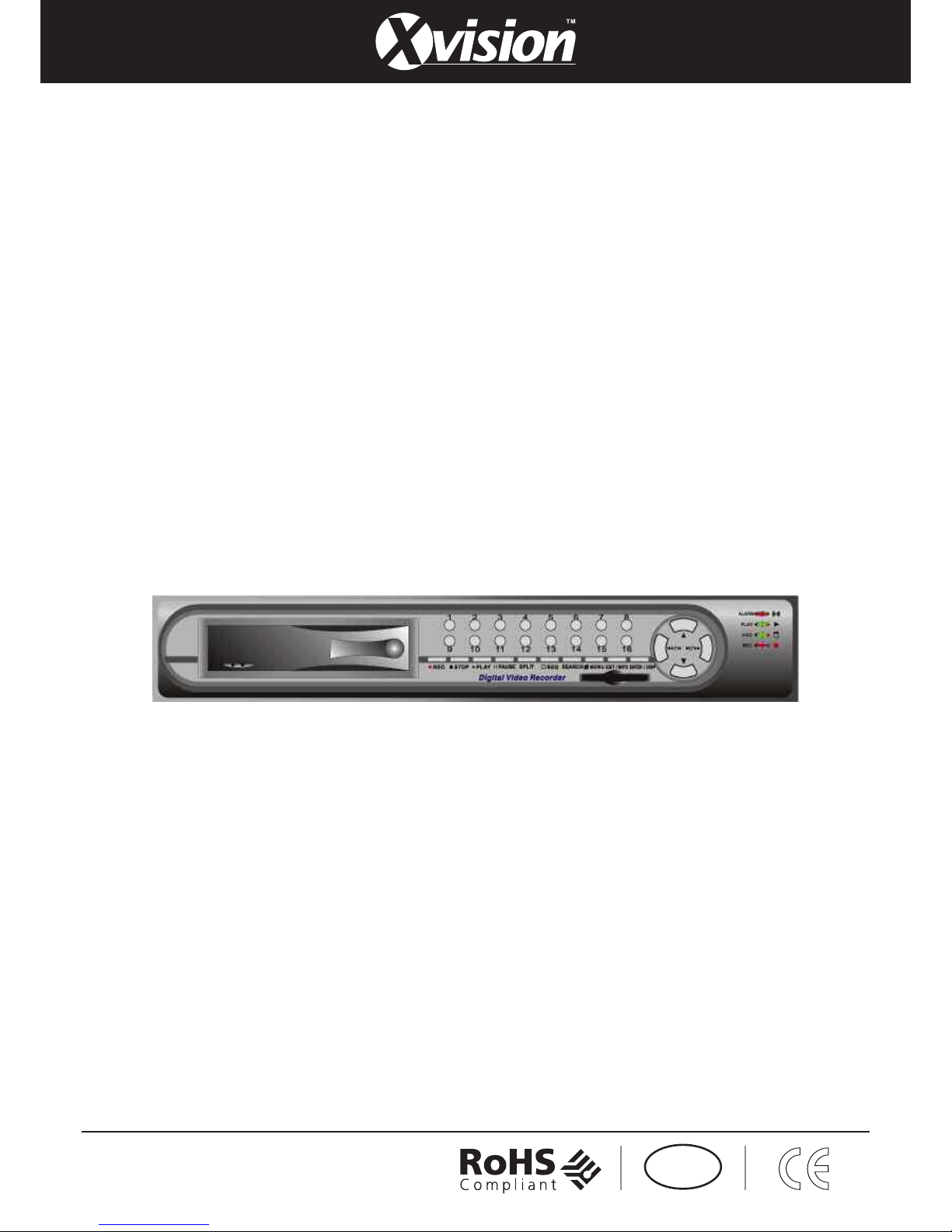
EVD16NCF
16 Channel MPEG4 DVR
UUL
L
Page 2

Contents
1. SAFETY PRECAUTIONS..................................................................................3
2. FEATURES ......................................................................................................... 4
3. PACKING LIST .................................................................................................. 5
4. NAME and FUNCTION of EACH PART .......................................................... 6
4.1 FRONT PANEL BUTTONS and CONTROLS...................................... 6
4.2 REAR PANEL BUTTONS and CONTROLS........................................7
5. INSTALLATION.................................................................................................8
6. OPERATION DESCRIPTIONS........................................................................ 10
6.1 LIVE MODE......................................................................................... 10
6.2 RECORD MODE.................................................................................. 12
6.3 PLAYBACK MODE............................................................................. 13
6.4 SEARCH ............................................................................................... 14
7. MENU SETUP DESCRIPTION.......................................................................15
7.1 EIGHT/ SIXTEEN CAMERA MODE RESCAN................................. 16
7.2 DATE/ TIME SETUP ........................................................................... 16
7.3 CAMERA SETUP................................................................................. 17
7.3.1 EDIT CAMERA TITLE 1-8 .............................................................. 17
7.3.2 EDIT CAMERA TITLE 9-16 ............................................................ 18
7.3.3 VIDEO ADJUST................................................................................18
7.3.4 MOTION DETECTION..................................................................... 19
7.4 RECORD SETUP.................................................................................. 20
7.5 SCHEDULE SETUP............................................................................. 21
7.6 HARD DISK SETUP............................................................................22
7.7 CF CARD SETUP.................................................................................23
7.7.1 CF CARD COPY ............................................................................... 23
7.8 OTHERS ............................................................................................... 24
7.8.1 PASSWORD ...................................................................................... 25
7.8.2 BUZZER ............................................................................................ 26
7.8.3 RELAY OUTPUT.............................................................................. 26
7.8.4 ALARM INPUT.................................................................................27
7.8.5 SQUENCE DWELL TIME................................................................28
7.9 FACTORY DEFAULT.........................................................................28
8. NETWORK DVR SETUP ................................................................................ 29
8.1 Connecting Network DVR.................................................................... 29
8.1.1 Online using Intranet or Fixed IP....................................................... 29
8.1.2 Online using ADSL (PPPoE) Router ................................................. 29
8.1.3 Online using DDNS Server................................................................29
8.2 Online with DHCP Server..................................................................... 30
8.3 Online without DHCP Server................................................................31
8.4 Online Connection................................................................................. 32
8.4.1 Install ActiveX ................................................................................... 32
1
Page 3

9. FUNCTION SETUP.......................................................................................... 35
9.1 Main Display.........................................................................................35
9.1.1 View ................................................................................................... 36
9.1.2 Image Recording ................................................................................ 36
9.1.2.1 Save as JPEG:.................................................................................. 36
9.1.2.2 Save as AVI:.................................................................................... 37
9.2 Advanced Setup..................................................................................... 39
9.2.1 Network Setting.................................................................................. 39
9.2.2 User Setup .......................................................................................... 40
9.2.3 DDNS Setup....................................................................................... 41
10. TROUBLESHOOTING .................................................................................. 42
11. NETWORK INSTALLATION........................................................................ 43
11.1 System Configuration..........................................................................43
11.2 Suggested PC Equipment.................................................................... 43
12. HARD DISK INFORMATION.......................................................................44
13. APPENDIX......................................................................................................45
13.1 DB25 Alarm Input/Relay Output Definition....................................... 45
13.2 List of Tested Hard Disk Drive...........................................................45
13.3 List of Tested Compact Flash Card..................................................... 45
14. SPECIFICATION............................................................................................ 46
The author assumes no responsibility for any errors or omissions that may appear in this
document nor does the author make a commitment to update the information herein.
VER.:1.0, P/N.: 040150/1
2
Page 4
3
1. SAFETY PRECAUTIONS
CAUTION
RISK OF ELECTRIC SHOC K.
DO NOT OPEN!
CAUTION :
TO REDUCE THE RISK OF ELECTRICAL SHOCK,
DO NOT OPEN COVERS (OR BACK).
NO USER SERVICEABLE PARTS INSIDE.
REFER SERVICING TO QUALIFIED
SERVICE PERSONNEL.
It is advised to read the Safety Precaution Guide through carefully before operating the
product, to prevent any possible danger.
WARNING: This symbol is intended to alert the user to the presence of un-insulated
“ dangerous voltage”.
CAUTION: This symbol is intended to alert the user to presence of important operating and
maintenance (Servicing) instructions in the literature accompanying the
appliance.
Disposal of Old Electrical & Electronic Equipment (Applicable in the European
Union and other European countries with separate collection systems).
This symbol on the product or on its packaging indicates that this product shall not be treated as
household waste. By ensuring this product is disposed of correctly, you will help prevent
potential negative consequences for the environment and human health, which could otherwise be
caused by inappropriate waste handling of this product. The recycling of materials will help to
conserve natural resources. For more detailed information about recycling of this product, please
contact your local city office, your household waste disposal service or the shop where you
purchased the product.
The power cord is the main power connection. Therefore, constantly plug and unplug of the
power cord might result in malfunction of the product.
Do not install the product in an environment where the humidity is high.
Unless the product is waterproof or weatherproof, otherwise poor image quality may occur.
Do not drop the product or subject them to physical shocks.
Except for vandal-proof or shockproof product, otherwise malfunctions may occur.
Never keep the product to direct strong light.
It can damage the product.
Do not spill liquid of any kind on the product.
If it gets wet, wipe it dry immediately. Alcohol or beverage can contain minerals that corrode the
electronic components.
Do not expose to extreme temperatures.
Use the product at temperatures within 5℃ ~ 40℃.
Page 5

4
2. FEATURES
16-Channel video recording and 1-Channel audio recording.
1-Video outputs to monitor, 1-video output to SPOT, and 2-audio outputs.
Auto NTSC/ PAL video format detection.
Auto video loss detection and alarm alert.
16-Alarm signal input and 1-Relay output (auto alarm recording).
High-capacity removable hard disk (up to 500 GB capacity), digital image
storage replaces tape-based mechanical systems.
Auto overwrite or alarm notification when hard disk is full, reduces manpower
management.
Power-loss memory function, designed to reboot and continue recording.
MPEG4 videos and G.726 audio compression format.
Maximum recording rate is 60fps@352x240 (NTSC) or 50pfs@352x288
(PAL).
Maximum recording rate is 30fps@704x240 (NTSC) or 25pfs@704x288
(PAL).
Adjustable recording quality and frame rates for recording.
4 Types of record mode: Manual, Schedule Alarm, Schedule Motion Detection
and Schedule Continue.
Monitoring or recording can be shown by full or split screen display, and auto
sequential switching.
Quick efficient playback search by Date & Time.
Recorded images backup is applicable by Compact Flash card (PC supports
ASF file playback).
Includes RJ-45 interface for network connection (optional).
Firmware update by Compact Flash card.
Page 6
3. PACKING LIST
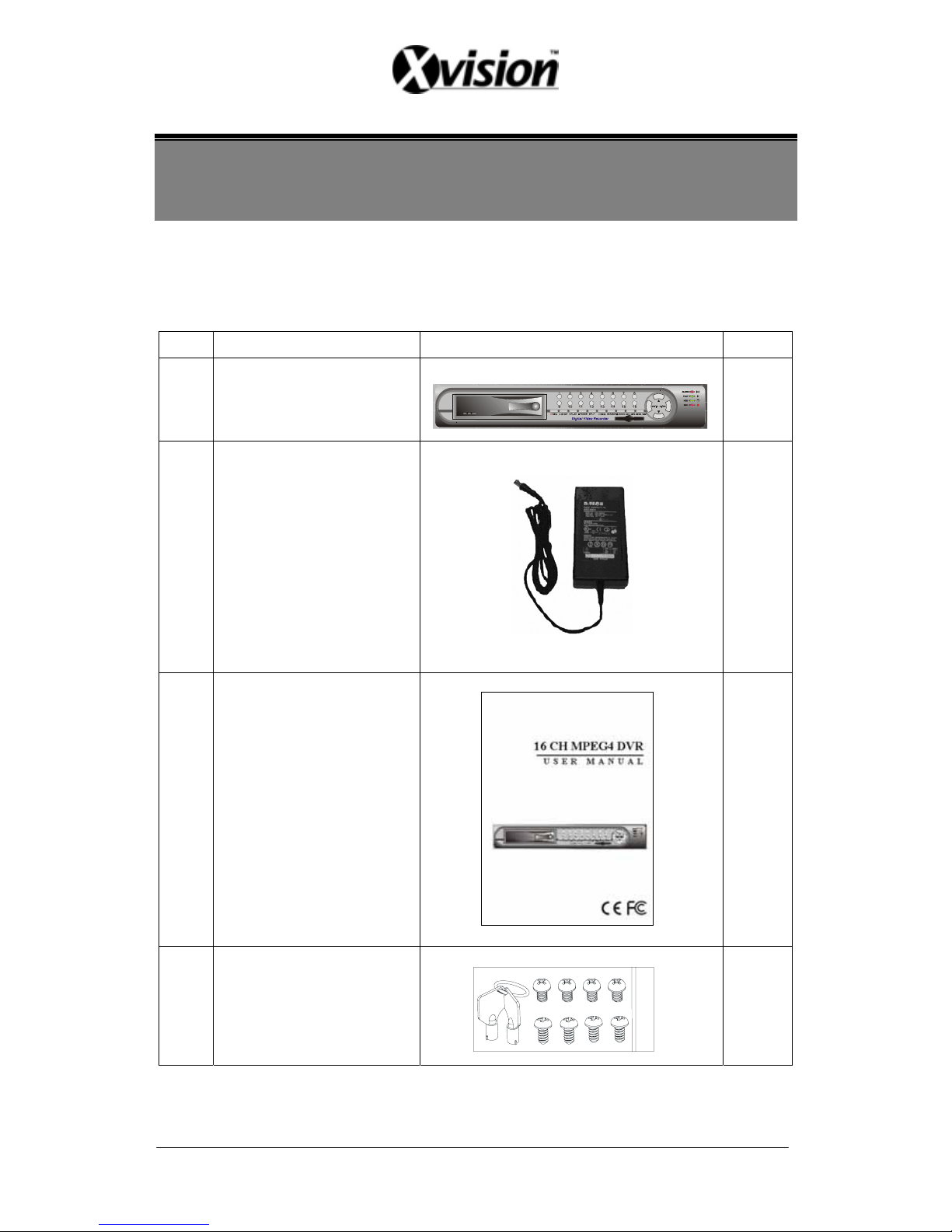
Check and make sure all the items shown below are included in your product package.
If something is missing, contact your dealer as soon as possible.
No. Item Picture Quantity
1
DVR
(Digital V ideo Recorder)
1
2
Power Adaptor
and Power Cord
Input: AC 100~240V
Output: DC 12V/4.2A
1
3 Manual
1
4
Hard Drive Cartridge Key Lock
(optional)
And Fixed Screws
1
5
Page 7
6
4. NAME and FUNCTION of EACH PART
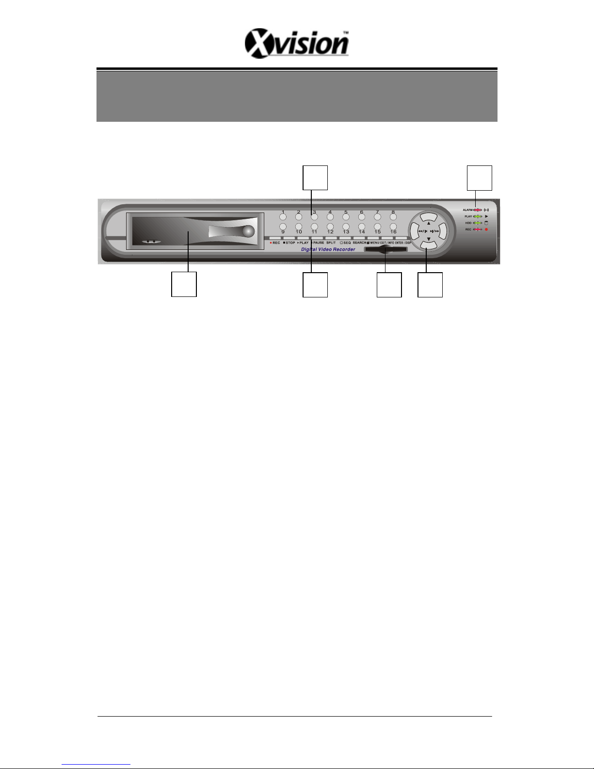
4.1 FRONT PANEL BUTTONS and CONTROLS
1. Camera Select (1-16 Video Channel Button)
2. LED Indicator (Alarm/ Playback/ HDD/ Record).
3. Removable Cartridge Casing: 3.5” IDE HDD, Max.: 500 GB (optional).
4. Function Button:
REC: Manual Record.
STOP: Stop Button (Manual Record/ Play).
PLAY: Play Button.
PAUSE: Pause Button.
SPLI T: Full Screen/ Quad Screen/ 9-Split Screen/ 16-Split Screen (switching
channels).
SEQ: Auto Sequencing Button.
SEARCH: Quick Search on Data Recorded.
MENU: Menu Setup Button.
EXIT/ INFO: Return to Previous Menu/ System Information Display Switch.
ENTER/ DISP: Confirm Button/ Message Display Switch.
5. CF Card Slot: Insert the CF card to backup the recording material and to
upgrade the system software etc.
6. Direction Button:
LEFT: Decreases the Setting Value under the Menu/ Step Rewind
Playback/ Fast Rewind Playback (speed adjustable).
RIGHT: Increases the Setting Value under the Menu/ Step Forward
Playback/ Fast Forward Playback (speed adjustable).
UP: Moves the Cursor Upward/ Forward Switching Channel Display.
DOWN: Moves the Cursor Downward/ Rewind Switching Channel Display.
2
4 6 5
3
1
Page 8
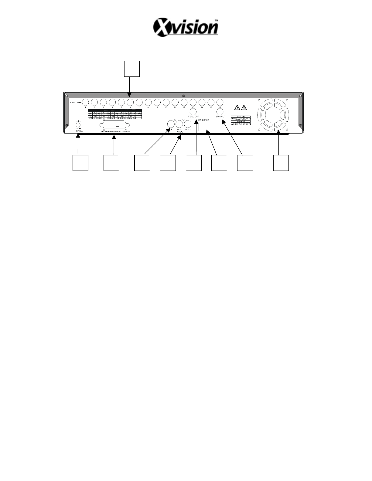
4.2 REAR PANEL BUTTONS and CONTROLS
1
7
9 82 63 54
7
1. Video Input: 16-Channel BNC Input Terminal
2. DC Power Input: 12V/4.2A
3. Alarm Input/ Relay Output: DB25 Female Terminal (Please refer to appendix)
4. Audio Input: 1-Channel RCA Input Terminal
5. Speaker Output: 2-Channel BNC Output Terminal
6. Main Monitor Output: 1-Channel BNC Output Terminal
7. Network Connection: 1-Ethernet Connection Terminal (optional)
8. SPOT Monitor Output: 1-Channel BNC Output Terminal
9. Fan
Page 9
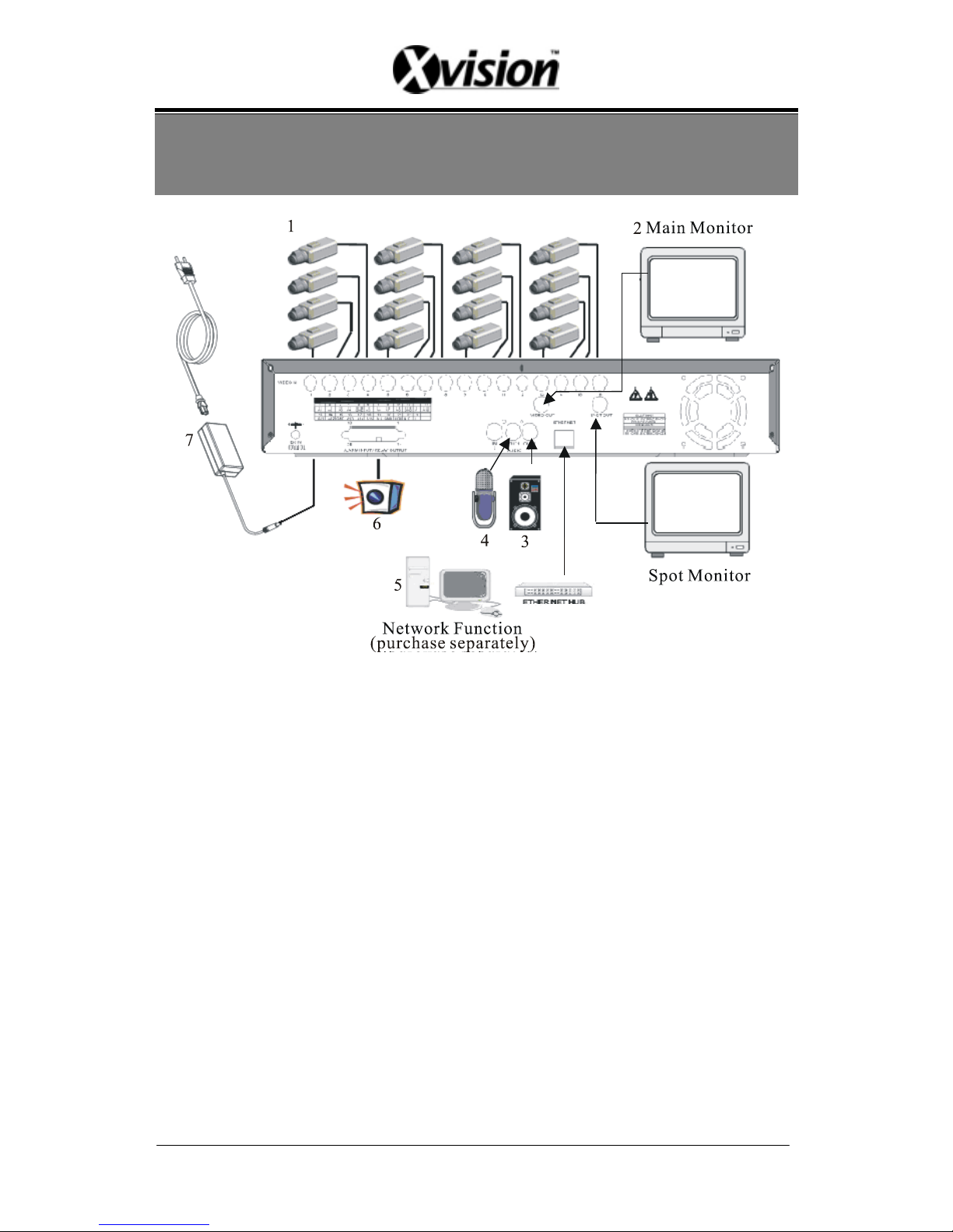
5. INSTALLATION
1. Connect the camera output (1 - 16) to video input (VIDEO IN) of the DVR.
2. Connect the monitor to the main monitor output (VIDEO OUT) of the DVR.
3. Connect the speaker to the speaker output (AUDIO OUT) of the DVR.
4. Connect the microphone output (1) to audio input (AUDIO IN) of the DVR.
5. Network function (purchase separately) connection.
6. Alarm Input/ Relay output:
16-Channel alarm input to DVR (ALARM1~16 and GND), or use relay output
signal from the DVR (N.C./ COM or N.O./ COM).
7. Use the supplied power adapter to connect this DVR to the power outlet.
8
Page 10

Note before operation
1. The DVR does not support HDD hot swap function. To prevent damage, please
enter main menu to stop all HDD activities, then power-off the device before
replacing the hard disk.
2. When the hard disk information icon turns to red, the device is notifying the user
to replace a new hard disk.
3. After power-on, system auto detects the video system (NTSC/ PAL) of the first
camera connected. When no camera has been connected, the video system will be
the same as previous setup.
4. After power-on the system auto enters 16-split screen mode, and previously setup
schedule recording mode.
9
Page 11

6. OPERATION DESCRIPTIONS
6.1 LIVE MODE
1. Press “DISP” button to switch “ON/ OFF” channel, date, and time message
display.
2. Press “INFO” to switch “ON/ OFF” system information display.
3. When the hard disk information icon turns to red, the device is notifying the
user to replace a new hard disk.
4. Press “CH” button to monitor full screen images (CH1 – CH16).
5. Press “SPLIT” button to switch to “Full Screen/ Quad Screen/ 9-Split Screen/
16-Split Screen” display. Under Full Screen/ Quad Screen/ 9-Split Screen, press
“UP/ DOWN” button to switch rewind/ forward in the form of the current split
screen display.
6. Press “SEQ” button to switch “ON/ OFF” sequencing order display. Full screen
channel auto sequence will skip the channel with video loss event.
7. When video loss occurs, video loss message will be shown on the screen.
8. During alarm triggered event the corresponding channel name will be changed
to color red (same result happens under Playback or Record mode).
9. Letter “M” is shown on the display of the channel with the motion triggered
event.
10. Connect the audio output to speaker input to enable live audio.
11. Live monitoring operations has not affect on recording functions.
12. When an alarm event occurs, SPOT monitor will immediately switch to the
video image of the channel that has been triggered, and until the duration time’s
up, it will return to the previous channel switching status.
10
Page 12
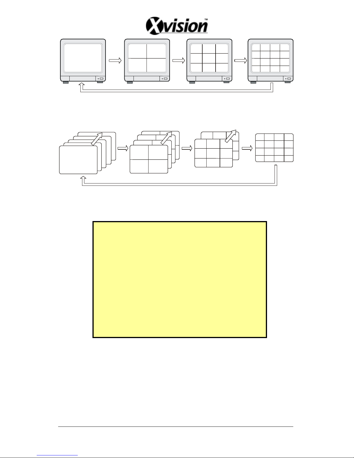
Full Display and Quad Display Switching Order
Full Display and Quad Display Sequencing Order
SYSTEM INFORMATION
SYSTEM VERS I ON : 1 .00B432529
IMAGE QUALITY : MED I UN
MANUAL I P S : 60
CONTINUE I P S : 60
MOT I ON
DETECTION I PS
: 60
A
LARM I PS
: 60
V
IDEO SI ZE
: 352 X 240
A
UDI O
: ON
D
ISK FULL
: OVERWR I T E
H
DD TOT AL CAP AC I TY
: 0MB
H
DD REMA I N CAPAC I TY
: 0MB
S
.M.A. R . T . STATUS
: NORMAL
System Information
11
Page 13
6.2 RECORD MODE
1. Live monitoring is operable during recording.
2. When the hard disk information icon turns to red, the device is notifying the
user to replace a new hard disk.
3. Manual Record: Under monitoring mode, press “REC” button to enable all camera
recordings, and “STOP” button to stop manual recording.
4. When schedule recording (ALARM/ MOTION DETECTION/ CONTINUE
RECORD) has been activated. Recording can not be stopped by pressing
“STOP” button, it is ineffective during schedule record time.
5. When the main password or the playback password is switched off, or the
password has been copied onto the CF card, and the CF card has been inserted.
Press PLAY or SEARCH button, system auto enters the playback or search
mode, and the will not request a password to be entered.
6. When the main password is switched off, or the password has been copied onto
the CF card, and the CF card has been inserted. Press MENU button, system
auto enters main menu, and will not request a password to be entered.
7. After entering playback mode or menu setup, when correct password has been
entered, all recording activities will stop. When exiting playback mode or menu
setup, once the schedule recording has been switched on, schedule recording
will auto start-up.
8. Power-on after power-loss, the system auto returns to the recording mode before
power-loss.
12
Page 14
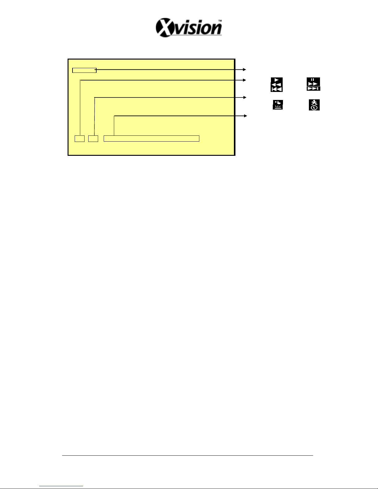
6.3 PLAYBACK MODE
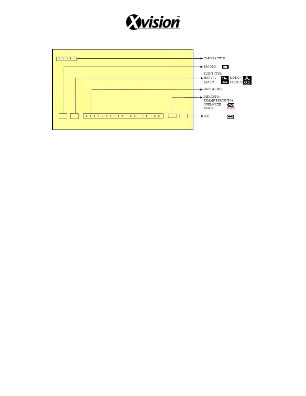
DOOR2 CAMERA TITLE
PLAYBACK PAUSE
REWIND FAST FORWARD
STEP BACKWARD STEP FORWARD
EVENT TYPE:
MANUAL MOTION
ALARM CONTINUE
DATE & TIME
2004/05/05 20:30:00
1. Press PLAY button, when playback password is setup to “ON”, system will
request to enter a password, when correct password has been entered, all
recording activities will stop.
2. When the main password or the playback password is switched off, or the
password has been copied onto the CF card, and the CF card has been inserted.
Press PLAY button, system auto enters the playback mode, and the password
will not be requested again by the system.
3. Press “DISP” button to switch “ON/ OFF” channel, date, and time message display.
4. Press “INFO” to switch “ON/ OFF” system information display.
5. Press “CH” button to playback full screen images (CH1 – CH16).
6. Press “SPLIT” button to switch to “Full Screen/ Quad Screen/ 9-Split Screen/
16-Split Screen” display. Under Full Screen/ Quad Screen/ 9-Split Screen, press
“UP/ DOWN” button to switch rewind/ forward in the form of the current split
screen display.
7. SEQ function is inapplicable during playback.
8. Press “PAUSE” button under normal playback to pause.
9. During pause status, press “LEFT” button to step rewind playback, and
“RIGHT” button to step forward playback.
10. During normal playback, press “LEFT” button to adjust the rewind
pla ybac k speed (x32/ x64 ), and “RIGHT” button to adjust forward playback
speed (x2/ x4/ x8/ x16/ x32/ x64). Press “PLAY” button to return to normal
speed and “PAUSE” button to pause.
11. Connect the audio output to the speaker input to simultaneously enable video
and audio playback.
12. Press “STOP” button to stop playback, and return to live monitoring mode or
schedule record mode.
13
Page 15
6.4 SEARCH
1. Press SEARCH button, when playback password is setup to“ON”, system will
request to enter a password, when correct password has been entered, all
recording activities will stop.
2. When the main password or the playback password is switched off, or the
password has been copied onto the CF card, and the CF card has been inserted.
Press SEARCH button, system auto enters the search mode, and will not
request a password to be entered.
3. Press SEARCH button for quick search function by date and time, press
ENTER or PLAY button to enter 16-split screen display.
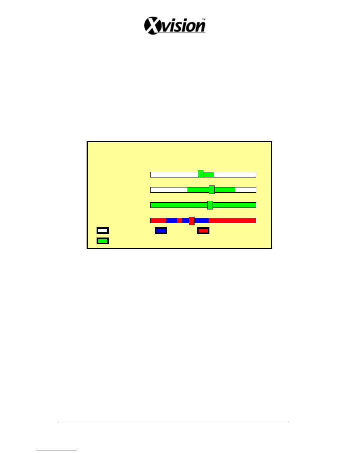
4. YEAR/ MONTH/ DAY/ HOUR:
data available under this date period.
5.
r Bar: No recorded available under this time period.
data, and
under this time
6. Use “UP/ DOWN” buttons to move the cursor to the desired item (YEAR/
7. “ENTER” or “PLAY” button to enter
SEARCH
YEAR 2005
MON 0 5
DAY 1 6
HOUR
13
MIN 23
NO D
ATA
CONT . MANUAL
MOT I ON
D
ATA
ALA
RM
White Index Bar: No recorded
Green Index Bar: Recorded data available under this date period.
MINUTE:
White Colo
Red Color Bar: Manual recorded data, motion detection recorded
alarm recorded data is available under this time period.
Blue Color Bar: Schedule recorded data is available
period.
MONTH/ DAY/ HOUR/ MINUTE), use “LEFT/ RIGHT” buttons or drag the
index bar to make changes on the setup.
After setup has been completed, press
play mode, or “EXIT” button to return to live monitoring mode.
14
Page 16

15
7. MENU SETUP DESCRIPTION
Password is requested after “MENU” button is pressed.
ENTER PASSWORD
XXXXXXXX
1. In order to enter the main menu, password entered must be correct. After
entering the main menu all recording activities will stop.
2. Default Password: 12345678 (CH1~CH8 represents number 1~8).
3. When the main password is switched off, or the password has been copied onto
the CF card, and the CF card has been inserted. Press MENU button, system
auto enters main menu, and will not request a password to be entered.
SETUP
[8/16 CAMERA MODERESCAN]
DATE / T IME >
CAMERA >
RECORD >
SCHEDULE >
HARD D I SK >
CF CARD >
OTHERS >
FACTORY DEFAULT >
Main Menu
Page 17

7.1 EIGHT/ SIXTEEN CAMERA MODE RESCAN
1. When only 8 cameras has been connected (whether it is the first 8 or last 8
cameras), the system will enter 8-ch monitoring display mode. For all cameras
to be displayed the system will have to reboot or enter the menu to re-detect
16-ch monitoring display mode.
2. When more than 8 cameras are connected, the system will enter 16-ch
monitoring display mode, and when disconnecting the cameras leaving only 8
cameras connected, the system will have to reboot or enter menu to re-detect
8-ch monitoring display mode.
3. Under 16-ch display mode, please avoid mix application on corresponding
channels (corresponding channels: 1-9, 2-10, 3-11,…, 8-16) of b/w and color
cameras; otherwise color cameras may be auto changed to b/w mode. Therefore,
connecting or disconnecting the cameras, the system will have to reboot or enter
menu to re-detect the monitoring display mode.
7.2 DATE/ TIME SETUP
DATE /TIME SETUP 1
DATE FORMAT:Y/M/D
DATE :2006 /05/05
TIME :20:30:00
DATE FORMAT (Three Types of Date Format Setup) :
1. Y/M/D: Year/ Month/ Day
2. M/D/Y: Month/ Day/ Year
3. D/M/Y: Day/ Month/ Year
16
Page 18

7.3 CAMERA SETUP
CAMERA SETUP 2
CH 1 - 8 TI TLE >
CH 1 - 1 6 T I TLE >
VIDEO ADJUST >
MOTI ON DETECTI ON >
7.3.1 EDIT CAMERA TITLE 1-8
ED I T CAMERA TI TLE 1 - 8 2 - 1
CH TITLE
1 CH1*****
2 CH2*****
3 CH3*****
4 CH4*****
5 CH5*****
6 CH6*****
7 CH7*****
8 CH8*****
[DEFAULT
]
1. Maximum 8 character title setups.
2. Move the cursor to the desired camera number by using “UP/ DOWN” button
3. Move between the characters (camera title) by using “LEFT/ RIGHT” button and
use “UP/ DOWN” button to edit the camera title (letters A-Z, numbers 0-9 or
blank spaces).
17
Page 19

7.3.2 EDIT CAMERA TITLE 9-16
ED I T CAMERA TI TLE 9 - 1 62- 2
CH TITLE
9 CH9*****
10 CH10****
11 CH11****
12 CH12****
13 CH13****
14 CH14****
15 CH15****
16 CH16****
[DEFAULT
]
7.3.3 VIDEO ADJUST
VIDEO ADJUST 2 - 3
CHANNE L : 0 1
BRIGHTNESS (1-10) :05
CONTRAST ( 1 - 1 0 ) : 0 5
SATURATION (1-10) :05
HUE ( 1-10) :05
[DEFAULT
]
Adjustable brightness, contrast, saturation, and hue for 1 –16 CH videos.
18
Page 20
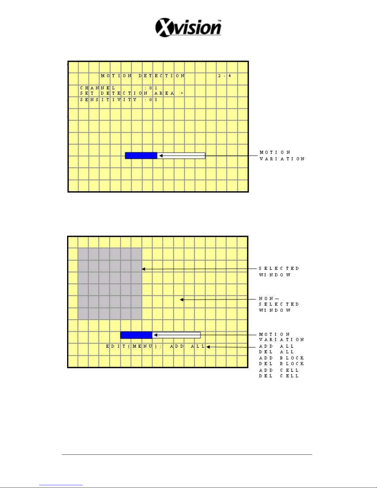
7.3.4 MOTION DETECTION
1. Select Camera Channel: 01 ~ 16
2. Select Motion Detection Sensitivity Rate: 01 ~ 05
3. Select “SET DETECTION AREA” to show the display below.
1. Blue bar shown above indicates the motion variation of the detection window,
when motion event exceeds the sensitivity setup, it triggers motion detection
recording.
2. Full Screen Display: NTSC and PAL are divided into16 x 12 detection blocks.
19
Page 21
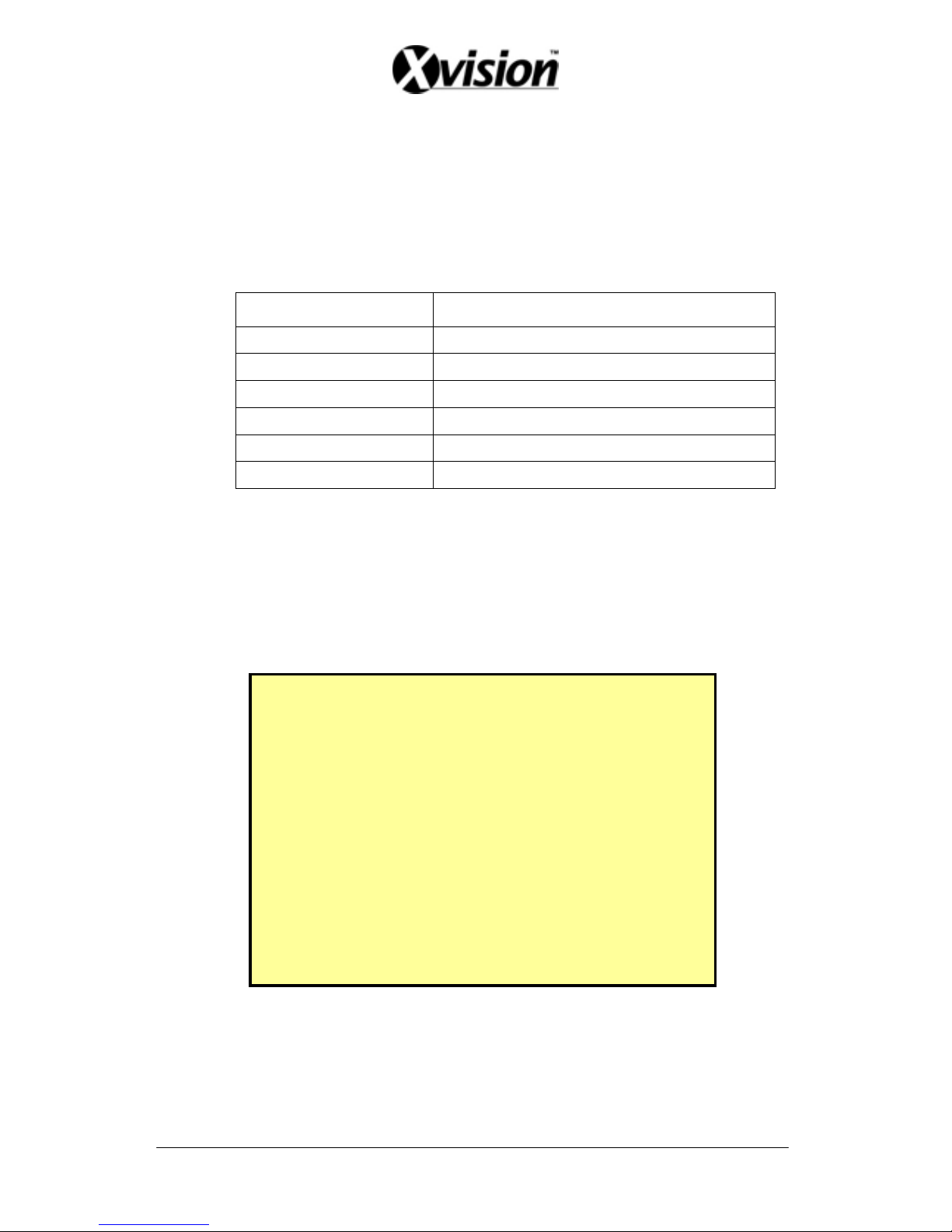
3. Area Block Color:
Yellow: Detection Block.
Transparent: Non-Detection Block.
4. Press “MENU” button to select motion detection function.
A. Cursor Movement: Press ▲/ ▼/ / button to randomly move the cursor.
B. Setup Motion Detection Area:
(1) Press “MENU” button, select motion detection edit function:
Function Description
Add Cell Enable single detection cell
Del Cell Disable single detection cell
Add Block Enable partial detection block.
Del Block Disable partial detection block.
Add All Enable all detection cells.
Del All Disable all detection cells.
(2) Press ENTER/ DISP button, switch the cursor to edit mode, or to confirm
detection block, and press <▲/ ▼/ / > button and use the above setup
guide to change the detection area (big or small).
7.4 RECORD SETUP
RECORD SETUP 3
QUAL I TY :MEDIUM
AUDI O : ON
DI SK FULL :OVERWR I TE
POST ALARM SEC : 1 0
MANUAL I P S : 6 0
CONTINUE I P S : 60
MOTI ON DETECT ION I PS : 6 0
ALARM I PS : 6 0
VIDEO SI
ZE :352 X
240
[DEFAULT
]
1. QUALITY: LOW/ MEDIUM/ HIGH.
2. AUDIO:
ON: Audio recording enabled.
OFF: Audio recording disabled.
20
Page 22

3. DISK FULL:
Overwrite: When the disk is full the system overwrites the old data
(overwriting from the oldest data)。
Stop: When the HDD is full the system stops recording (message will be
displayed).
4. POST ALARM: Recording time after an event (Alarm/ Motion Detection)
has been triggered.
5. MANUAL: IPS by manual recording.
6. CONTINUE: IPS by schedule continuous recording.
7. MOTION DETECT: IPS by schedule motion detection recording.
8. ALARM: IPS by schedule alarm recording.
9. VIDEO SIZE:
NTSC: 704x240/ 352x240
PAL: 704x288/ 352x288
10. DEFAULT: Reload the factory default setting.
7.5 SCHEDULE SETUP
SCHEDULE SETUP
4
SCHEDUL E : ON
11
012345678901
AAAAMMMCCAAA
11111111222
2
23456789012
3
- - - A MMMCC * * *
[DEFAULT
]
* : ALL - :NONE
A:ALARM M:MOTION C:CONT.
Three Types of Schedule Recording Setup:
1. Continue Record: Continuous recording according to the setup of the schedule time.
2. Motion Detect Record: Motion detection recording according to the setup of the schedule
time.
21
Page 23

3. Alarm Recording: Alarm trigger recording according to the setup of the schedule time.
Optional Settings: Each hour individually setup to different recording modes,
combined settings or even no settings are acceptable.
During schedule recording when manual recording is applied, the system auto
switches to manual recording (manual recording is the first priority recording).
Record Mode Priority:
Manual Record>Alarm Record>Motion Detection Record>Continuous Record
7.6 HARD DISK SETUP
HARD D I SK S ETUP
5
HDD TOTAL CAPACI TY : 1
2000
0MB
HDDREMAINCAPACITY:
250
0MB
BEGIN DATE : 2 005/01/05
END DATE :2005/01/13
FORMAT
>
1. Displays the hard disk total capacity and the remaining capacity.
2. Displays the begin and end date of the recorded material and when no recorded
materials are available, current date is displayed.
3. FORMAT: Format the HDD.
22
Page 24

7.7 CF CARD SETUP
CF DI SK SETUP 6
CF TOTAL CAPAC ITY : 2 50MB
CF REMAIN CAPACI TY : 120MB
CF CARD COPY >
[ BACKUP LOG F I LE ]
FORMAT
>
1. CF TOTAL CAPACITY: Total Capacity
2. CF REMAIN CAPACITY: Remaining Capacity
3. CF CARD COPY: Copy the selected file to the CF card.
4. FORMAT: Delete all data stored in the CF card.
7.7.1 CF CARD COPY
CF CARD COPY 6 - 1
CHANNEL : 0 1
AUD I O : ON
BEGI N :
2004/05 /03 12:20 :30
END :
2004/05 /03 12:25 :45
[
COPY
]
PROGRESS B
AR
1. CH: Selectable 1 -16 camera option.
2. AUDIO: Whether audio will be copied or not.
23
Page 25

3. BEGIN/ END: The system will start coping according to the setup (begin and
end time).
4. COPY: Select “COPY” to start copy.
*When the data size selected exceeds the storage capacity of the CF card, it will
start coping from the beginning and stop when CF card is full. Different channels
and different events setup generates different ASF files (audio data follows its
corresponding video file). PC supports ASF file playback.
7.8 OTHERS
OTHERS SE TUP 7
PASSWORD :ON
SET PASSWORD >
KEY STOP BUZZER/ RELAY: ON
BUZZER >
RELAY OUTPUT >
ALARM INPUT >
SEQUENCE DWELL T IME>
COLOR BAR
LANGURAGE : ENGL I SH
1. PASSWORD:
ON: Enable password protection, password is required before entering the main menu.
OFF: Disable password protection, password will not be required before entering the
main menu.
2. KEY STOP BUZZER/ RELAY: When buzzer or relay device is triggered by an
event, press on any key to deactivate.
3. COLOR BAR: By using the color bar, the user may adjust the color of the
monitor.
24
Page 26

4. LANGUAGE: Supports English and Chinese on-screen menus and displays.
7.8.1 PASSWORD
SET PASSWORD 7 - 1
PASSWORD FOR PLAYBACK: ON
[ SAVE PAS SWORD TO C F CARD ]
NEW PASSWORD :XXXXXXXX
CONF I RM PAS SWORD : XXXXXXXX
1. Search/ Playback Password: Whether to enter the password during search or
playback.
2. When password is stored on the CF card, after inserting the CF card the
password will not be requested by the system.
3. Default Password: 12345678 (CH1~CH8 represents number 1~8).
4. Press “ENTER” button to enter new password, confirm settings, and press
“EXIT” button to exit.
5. For long- hour searching, one may disable the playback password and enable it
after searching has been completed.
25
Page 27

7.8.2 BUZZER
BUZZER SETUP
7-2
BUZZER :ON
PERIOD
KEY BEEP :OFF
VIDEO LOSS :ON 06 SEC
ALARM :ON 06 SEC
MOTION DETECT ION: OFF 0 6 SEC
DISK FULL :OFF 06 SEC
[DEFAULT ]
BUZZER: Embedded buzzer sounding.
ON: Buzzer is enabled.
OFF: Buzzer is disabled.
Period: Duration time of the buzzer output.
Buzzer event includes the following:
1. KEY PRESSED: Key press beeping.
2. MOTION DETECTION: Triggered by motion detection.
3. ALARM: Triggered by external alarm.
4. VIDEO LOSS: Triggered by video loss.
5. DISK FULL: Triggered when disk full, system stops recording.
7.8.3 RELAY OUTPUT
RELAY OUTPUT SETUP
7-3
RELAY OUTPUT :ON
PERIOD
VIDEO LOSS :ON 06 SEC
ALARM :ON 06 SEC
MOTION DETECT ION: OFF 0 6 SEC
[DEFAULT ]
26
Page 28

RELAY OUTPUT: Relay output can be connected to external sounding device or
warning device.
Two Types (NO/ NC) of Relay Output Setup:
ON: Relay output enabled.
OFF: Relay output disabled.
PERIOD: Duration time of the relay output.
Relay output event includes the following:
1. VIDEO LOSS: Triggered by video loss.
2. MOTION DETECTION: Triggered by motion detection.
3. ALARM: Triggered by external alarm.
7.8.4 ALARM INPUT
ALARM I NPUT SETUP 7 - 4
A
L 1111111
CH L1234567890123456
OOOOOOOOOOOOOOOOO
[DEFAULT
]
+ :EACH
- :DISABLE O:NO C:NC
Sensor Type:
NC → Normal Close Alarm ( TTL level input )
Setup NC (Normal Close), the alarm will be triggered during NC status.
NO → Normal Open Alarm ( TTL level input )
Setup NO (Normal Open), the alarm will be triggered during NO status.
ALL
+ (EACH): Alarm input can be individually setup to NC or NO.
- (DISABLE): Disable all alarm input function.
C: All alarm input is setup to NC.
O: All alarm input is setup to NO.
27
Page 29

7.8.5 SQUENCE DWELL TIME
SEQUENCE DWELL S ETUP
7-5
DWELL
SEQUENCE : 03SEC
SPOT MONITOR :03SEC
SPOT MON I TOR ALARM:05SEC
[DEFAULT
]
1. SEQUENCE: Main display sequence dwell time setup.
2. SPOT MONITOR: SPOT monitor dwell time setup.
3. SPOT MONITOR ALARM: SPOT monitor alarm dwell time setup.
7.9 FACTORY DEFAULT
FACTORY DEFAULT SETUP
8
RECALL DEFAULT NOW?
[
YES]
[
NO ]
To return to factory default setting, select “YES” option and then press “ENTER”
button to reload the factory default setting. Press “EXIT” to exit.
28
Page 30

29
8. NETWORK DVR SETUP
Before installing the Network DVR, you need to first setup an IP Address, connect it
to the ADSL Modem or LAN Hub, and use IPEdit.exe to test the DVR.
Note: Before using PPPoE and DDNS connection method, one must first setup an IP
Address (using IPEDIT.exe).
8.1 Connecting Network DVR
3 methods for connecting Network DVR:
1. Online using Intranet or Fixed IP
2. Online using ADSL (PPPoE) Router
3. Online using DDNS Server
8.1.1 Online using Intranet or Fixed IP
Setup similar to “8.2 Online with DHCP Server” .
8.1.2 Online using ADSL (PPPoE) Router
Setup similar to “9.2.1 Network Setting”.
8.1.3 Online using DDNS Server
The DDNS service provides the dynamic IP to users to gain access to resources
connected to the Internet via a cable or DSL connection. Once you’ve decided to
apply this function, please register your domain name at http://www.dyndns.org (this
website supports register free service). Paid DDNS service is applied to long-term
users. For more information, please refer to
“9.2.3 DDNS Setup”.
Page 31
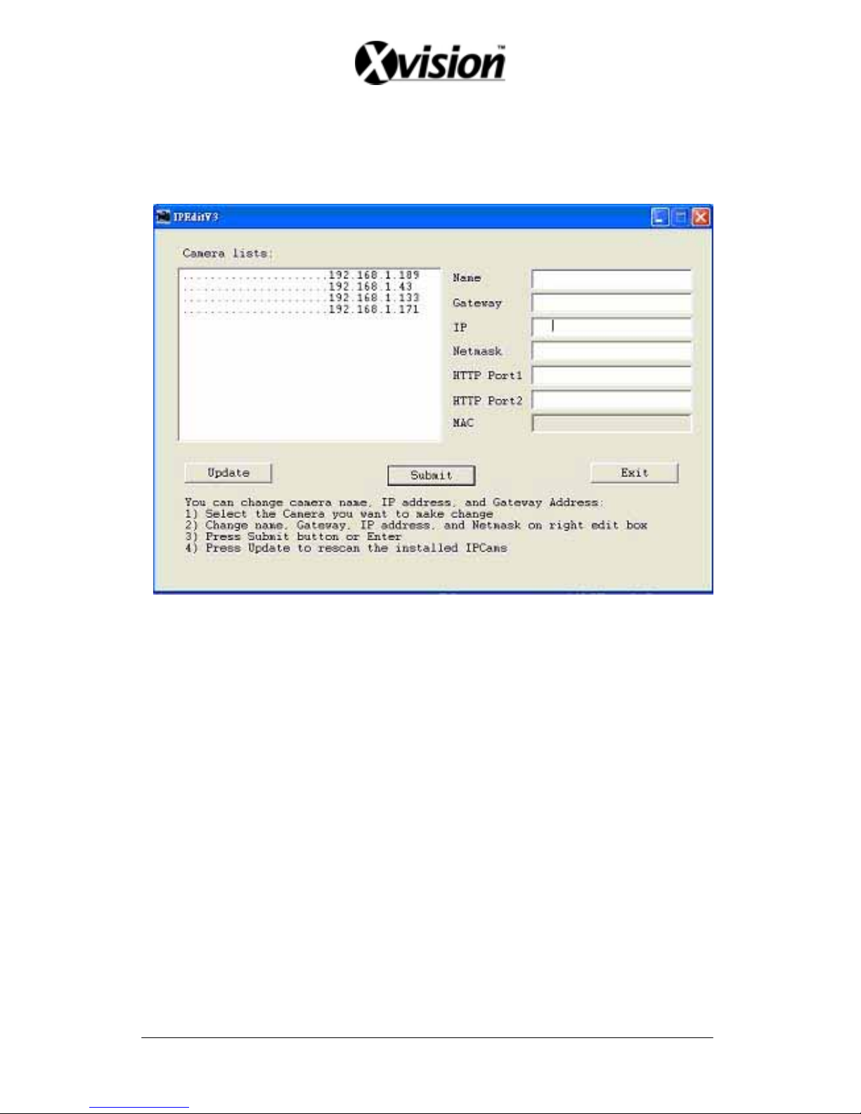
8.2 Online with DHCP Server
Use IPEDIT.exe to find the installed Network DVR. Select this Network DVR in the
Camera List Window. The default configuration will be shown on the right window.
Update the IP status.
Online with DHCP Server
30
Page 32
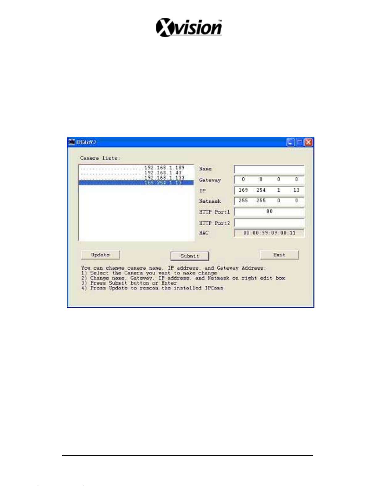
8.3 Online without DHCP Server
1. Use IPEdit.exe to find the installed Network DVR.
2. The Internet DVR without IP allocated by DHCP will have a default IP
Address of 169.254.1.13.
3. Select this Internet DVR on Camera List Window.
4. The default configuration will be shown on the right window.
5. Under DOS mode enter “IPCONFIG” to access Geteway, IP, and Netmask
setting values.
Online without DHCP Server
After the “Submit” button is clicked, the IP information of this Network DVR will be
updated.
31
Page 33
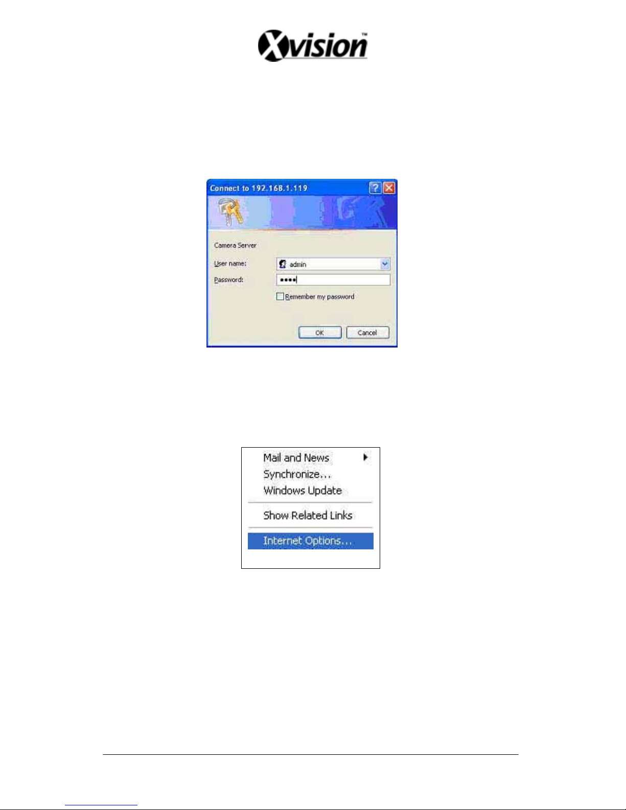
8.4 Online Connection
Start the Internet Explorer, enter the IP Address of the Network DVR into the
Address field, such as 192.168.1.31 or click twice on IPEdit.
Before connection, “User name” and “Password” will be requested:
Default User Name: admin (characters capitalize/ un-capitalize )
Default Password: 1234
8.4.1 Install ActiveX
Before entering remote connection, please install ActiveX and check your
browser setup by following the procedures below:
a. Open Internet Explorer under “Tools”, select “Internet Options”.
Tools Internet Options
b. Select “Security”, and then press “Custom Level”.
32
Page 34
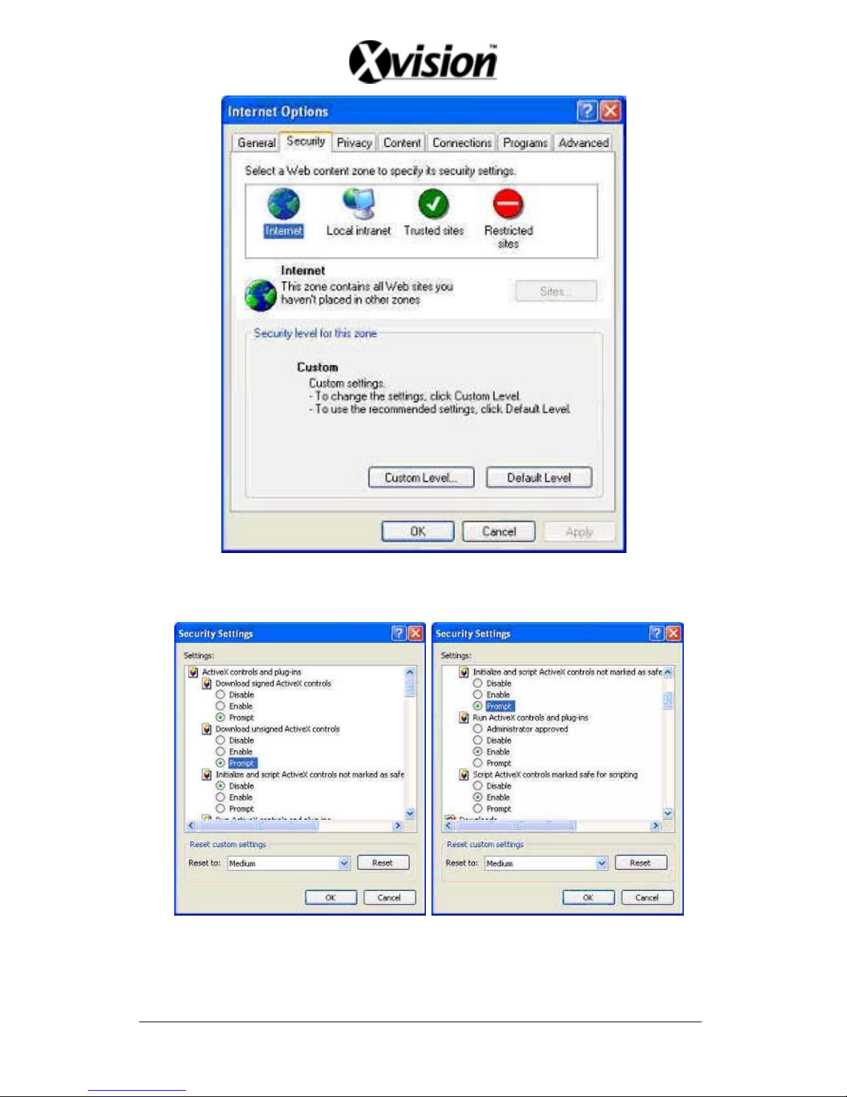
Safety->Internet Explorer->Setup level
Start ActiveX Control
33
Page 35
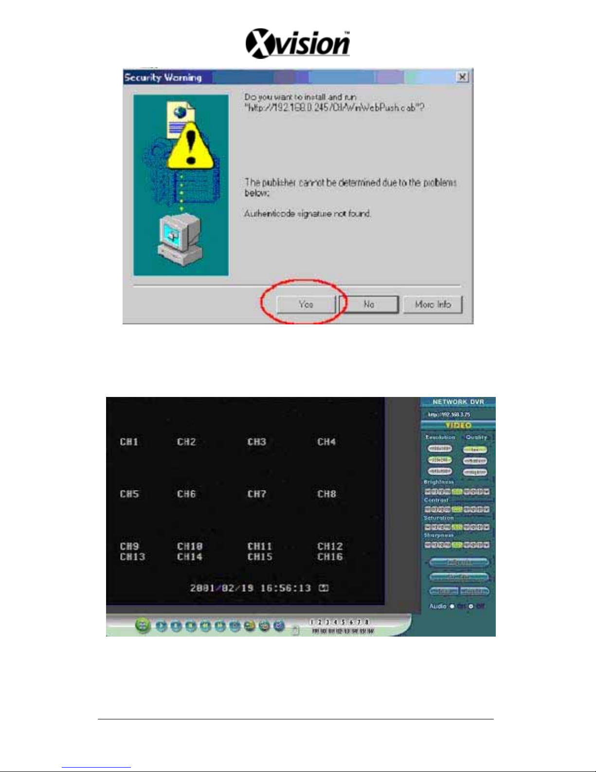
When ActiveX control installation has been completed, live images will be shown on the
display.
Connect to Network DVR through browser.
34
Page 36
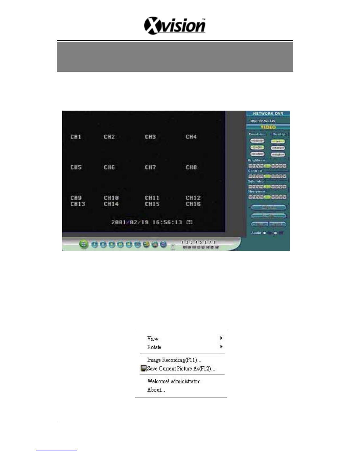
9. FUNCTION SETUP
9.1 Main Display
Best browsing resolution is 1027x768.
①
③ ④
⑤
⑥
⑦
⑧
○
9
○10
○
1
Live Display
Move the cursor inside the image range, right mouse click to display 5 function selections:
• View/ Make changes on image display
• Image Recording/ Record function setup
• Save Current Picture/ Save the current image
• Welcome! Administrator/ Display current user name
• About/ Version Description
35
Page 37
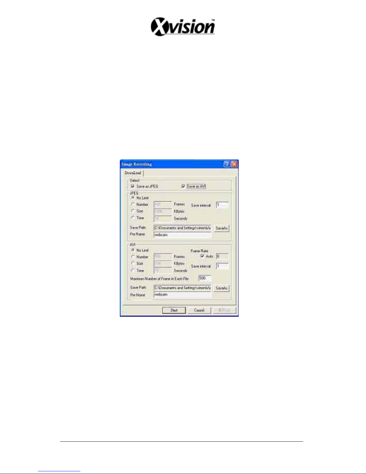
9.1.1 View
Two types of display method:
1. Resizable: Adjustable image size.
2. Actual size: The actual image size.
3. Status Bar: Reveals current status.
9.1.2 Image Recording
Image Recording Setup Display:
1. Save as JPEG: Save as picture file
2. Save as AVI: Save as AVI animation file
Note: To prevent asynchronous AVI recording, both function may not be simultaneously selected.
9.1.2.1 Save as JPEG:
• No Limit: Unrestricted image storage (continuous).
• Number: Image storage according to “number”.
• Save interval: Image storage according to “1/10 second” (e.g.: Enter “10”,
then 1 frame is stored per second. Enter “50”, then 1 frame is stored in 5
seconds).
• Size: Image storage according to “size”.
• Time: Image storage according to “time”.
• Save Path: Image storage according to “Save Path”.
• Pre Name: Image storage according to “Prefix Name”.
36
Page 38
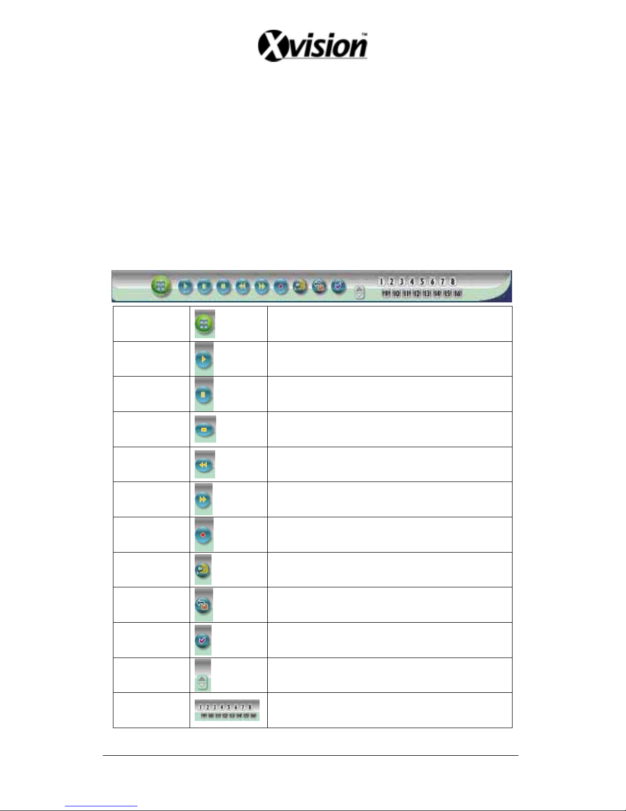
9.1.2.2 Save as AVI:
• No Limit: Unrestricted image storage (continuous).
• Number: Image storage according to “number”.
• Save interval: Image storage according to “1/10 second” (e.g.: Enter “10”, then 1
avi file is stored per second. Enter “50”, then 5 avi files are stored in 5 seconds).
• Size: Image storage according to “size”.
• Frame Rate: Image storage according to “frame rate”.
• Time: Image storage according to “time”.
• Maximum Number of Frame in Each File: Image storage according to “maximum
frame”.
• Pre Name: Image storage according to “Prefix Name”.
• Save Path: Image storage according to “Save Path”.
②
DVR Control
When the system is DVR, DVR control is shown by the diagram below:
SPLIT
Full Screen/ Quad Screen, 9-Split Screen, 10-Split
Screen.
PLAY
Play button.
PAUSE
Pause button.
STOP
Stops manual recording and playback.
REW
Relate to direction button (left).
FF
Relate to direction button (right).
REC
Manual record button.
SEARCH
Supports quick search of recorded videos.
EXIT/INFO
Return to Previous Menu/ System Information
Display Switch. Confirm Button/ Message
Display Switch.
ENTER/DISP
Return to Previous Menu/ System Information
Display Switch. Confirm Button/ Message
Display Switch.
UP/DOWN
Move cursor upward/ switch one channel
forward. Move the cursor downward/ switch one
channel backward.
CH
Camera select button: CH1~16 (relate to DVR
CH: 4CH/ 8CH/ 16CH display).
37
Page 39

③
Resolution Setting
176x144
352x288
704x576
120x160
320x240 (Pre-set Value)
640x480
Note: Resolution may differs according to different camera types (ex.: NTSC = 120x160,
320x240, or 640x480).
④
Quality Setting
High
Middle
Low (Pre-set Value)
⑤
Brightness/ Contrast/ Saturation/ Sharpness
- : Mini. Value
STD: Pre-set Value
+: Max. Value
The higher values are shown to the right and descend in value as you go to the left.
⑥
Configuration
Advance setup (this function is applicable only to Admin).
⑦
Live Video
Back to live video display.
⑧
Record
Please refer to 9.1.2 Image Recording.
○
9 Snapshot:
Press this button to capture one live image and press “RIGHT” button to store the image.
○
10 Audio
Live audio control “On/ Off” (IE Audio Pre-set: OFF).
38
Page 40
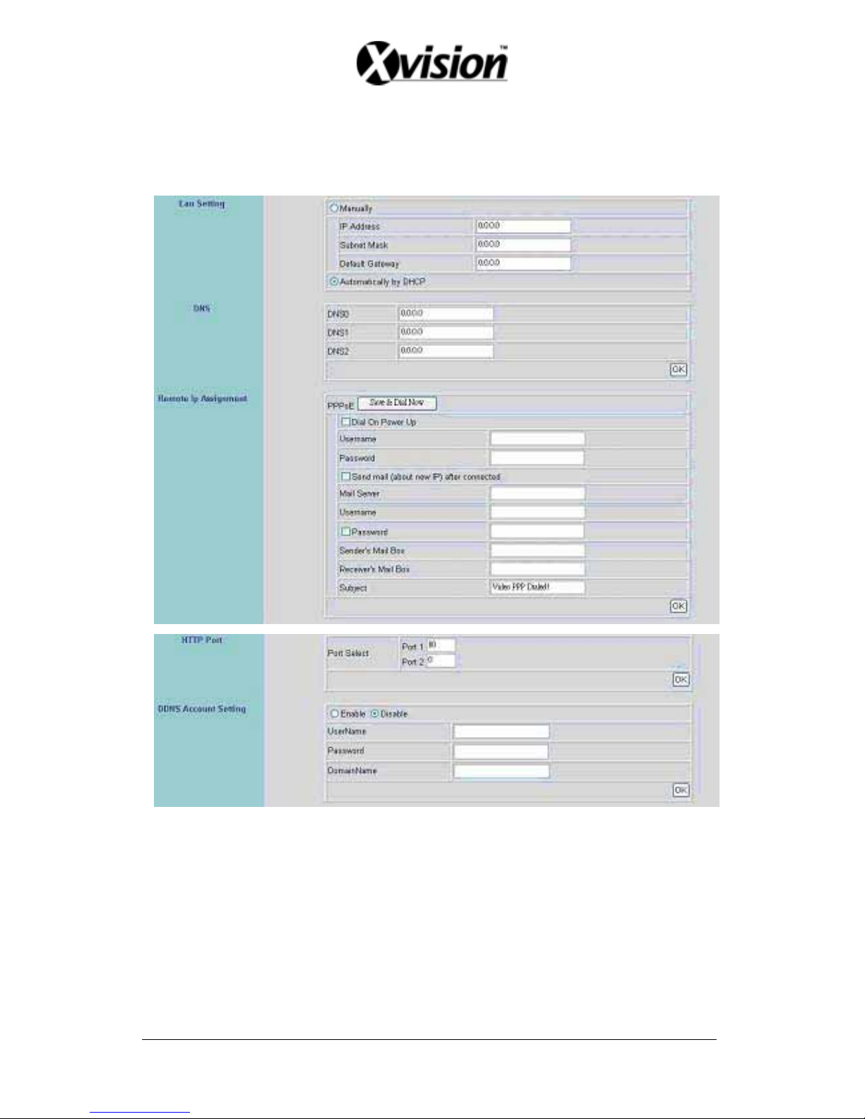
9.2 Advanced Setup
Only “Admin” can select “configuration” (advanced setup).
9.2.1 Network Setting
①
②
③
④
⑤
⑥
①
Lan Setting: LAN IP address setting is the same as IPEdit.
②
DHCP: Select item “Automatically by DHCP” to gain an IP address.
③
DNS: Fixed IP users needs to setup an IP address, please contact your local ISP dealer .
④
PPPoE: Connecting using ADSL, please contact your local ISP dealer. Select item
“Send mail (about new IP) after connected”, mail will automatically be
sent when connected to the ISP (as shown below).
Note: Please restart the Network DVR after setup has been completed
39
Page 41
⑤ Port Select: IP sharing device enables switching port function, setup the port and enter
http://XX.XXX.X.XX:8887 (as shown on the diagram above). Please restart the Video
Server after the setup has been completed, Port1=80 (Pre-set Value).
⑥ DDNS: To apply dynamic IP address, you may register at DDNS Server:
http://www.dyndns.org
To setup follow the steps below:
1. Register at DDNS Server: http://www.dyndns.org
2. Apply domain name.
3. Dial-up using ADSL Router: Click “Enable” button, then input your UserName,
Password, and DomainName (Similar to registering at DDNS Server).
Note: Please reboot after setup.
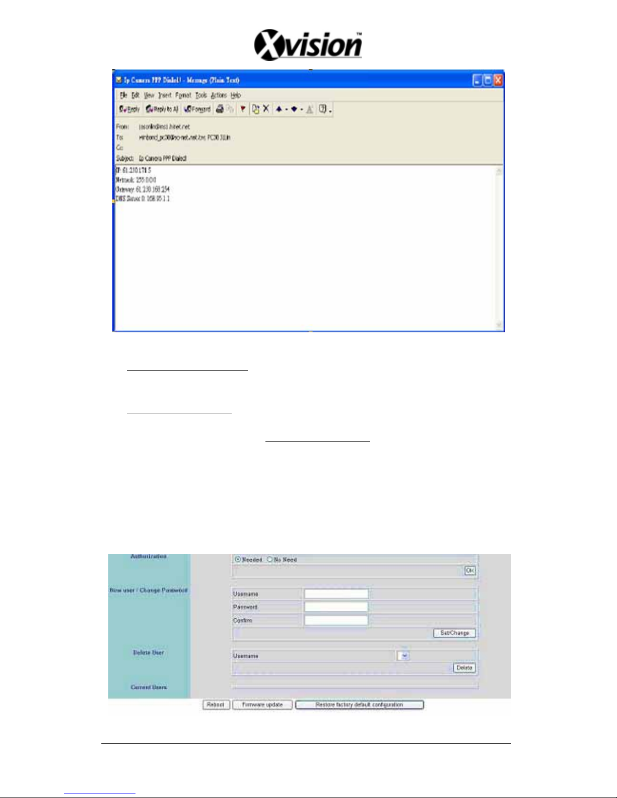
9.2.2 User Setup
40
①
②
③
④
⑤
⑦
⑥
Page 42
① Authorization: User Authorization Setting “Needed/ No Need”.
② New user/ Change Password: Add user or change password (Max. user = 30).
Note: Under the highest resolution, for optimum effect maximum of 20 users are
suggested (English/ Chinese Characters= 11).
③ Delete User: Delete user account.
④ Current Users: Currently registered users.
⑤ Reboot: Restart the Network DVR.
⑥ Firmware update: Updates the firmware.
○
7
Restore factory default configuration: Click “Restore factory default configuration” the
button to return to factory default settings (Please restart the Netw o r k D V R after setup
has been completed).
Note: Standard user may only view live display, record, and capture images.
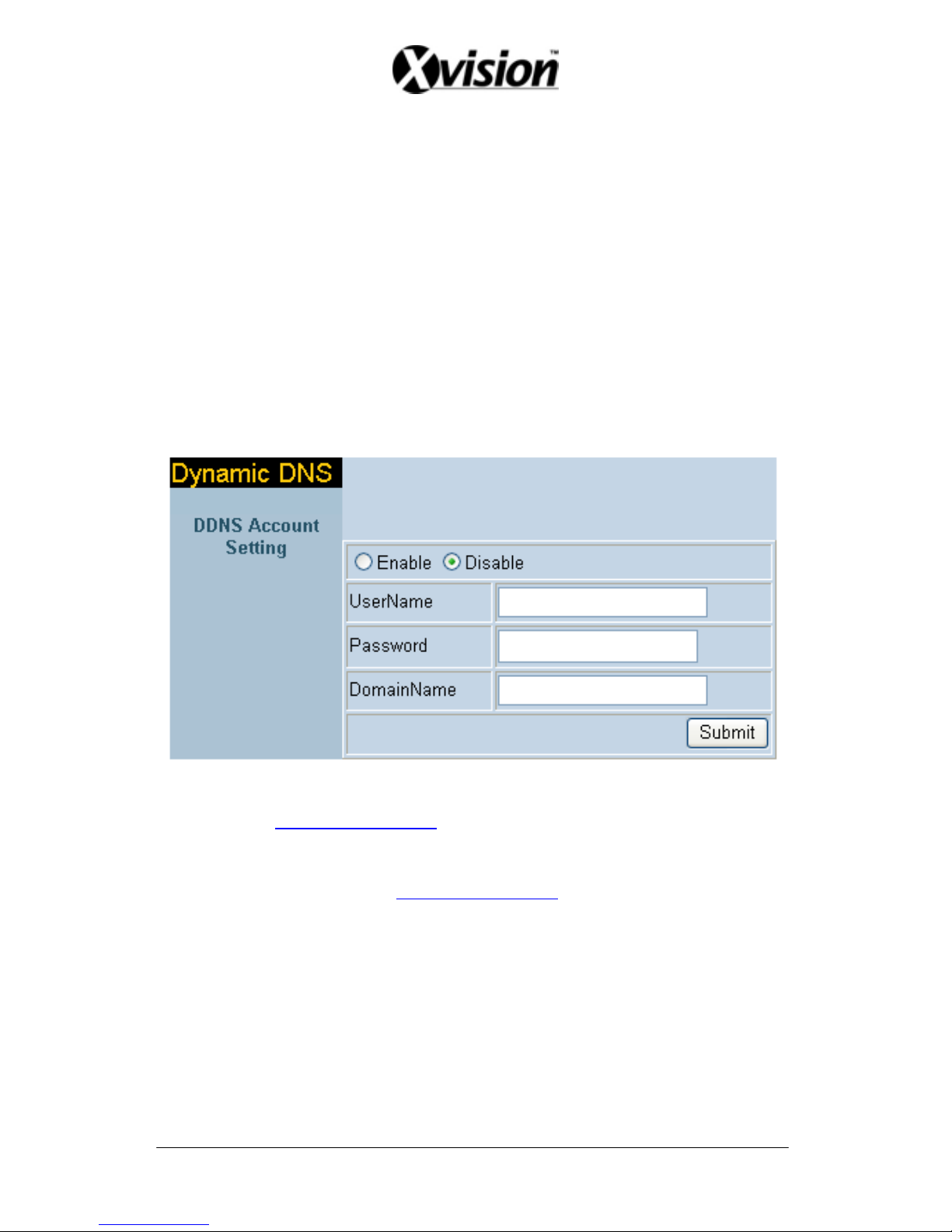
9.2.3 DDNS Setup
DDNS: To apply dynamic IP address, you may register at DDNS Server:
http://www.dyndns.org
To setup follow the steps below:
4. Register at DDNS Server: http://www.dyndns.org
5. Apply domain name.
6. Dial-up using ADSL Router: Click “Enable” button, then input your UserName,
Password, and DomainName (Similar to registering at DDNS Server).
Note: Please reboot after setup.
41
Page 43
42
10. TROUBLESHOOTING
Question Answer
Unable to detect the Network DVR
Reconnect the internet line and make
sure that it properly connected and
then restart the system.
No picture and sound
Check that everything is connected
properly (camera or microphone).
Reconnect everything, make sure that
the signal line is properly connected
and then restart the system.
No images is shown on the web page
Please follow “8.4.1 Install ActiveX”,
setup the IE, and install ActiveX.
IPEdit unable to detect the IP Address
Please check your software, some
software (e.g.: firewall or anti-virus
software) may block-out IPEdit
software.
Page 44
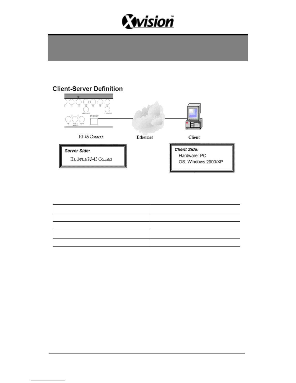
11. NETWORK INSTALLATION
11.1 System Configuration
Note: Before installation, connect the video input first and then power-on.
11.2 Suggested PC Equipment
CPU 1G (Above)
RAM 256M (Above)
Sound Card YES
Office System (OS) Microsoft Windows 2000/ XP
Monitor Resolution 1024x768 (Above)
43
Page 45
44
12. HARD DISK INFORMATION
1. Supports 3.5” ATA 2/ 3/ 4/ 5/ 6 format hard disk.
2. Enables installation of both built-in and removable hard disk.
3. Support high-capacity hard disk storage (up to 500 GB capacity).
4. Hot swap function is not applicable. To prevent damage, please enter the main
menu to stop all HDD activities, then power-off the device before replacing the
hard disk.
5. When the hard disk information icon turns to red, the device is notifying the user
to replace a new hard disk.
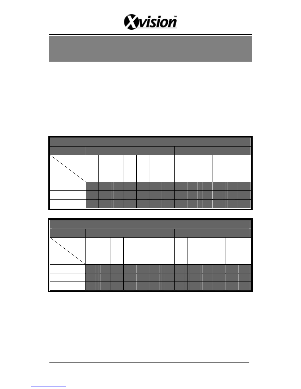
500GB HDD - Possible Recording Time per Day (NTSC)
Video Size 352 X 240 704 X 240
Frame Rate
(Field/ Sec.)
Image Quality
60 30 15 8 4 2 1 30 15 8 4 2 1
High
14 24 40 71 121 220 387 16 30 45 82 148 269
Medium
18 29 48 83 140 250 427 19 36 53 96 172 303
Low
30 47 76 126 205 346 564 29 53 76 138 241 408
500 GB HDD - Possible Recording Time per Day (PAL)
Video Size 352 X 288 704 X 288
Frame Rate
(Field/ Sec.)
Image Quality
50 25 12 6 3 2 1 25 12 6 3 2 1
High
16 26 44 78 133 205 363 19 35 53 96 149 275
Medium
20 32 53 93 156 238 408 24 42 70 110 168 305
Low
33 52 83 141 228 335 546 34 62 91 160 240 408
Note: Tables above are for reference only. The recording time per day may differ
depending on the actual recording environment, please take note!
Page 46
45
13. APPENDIX
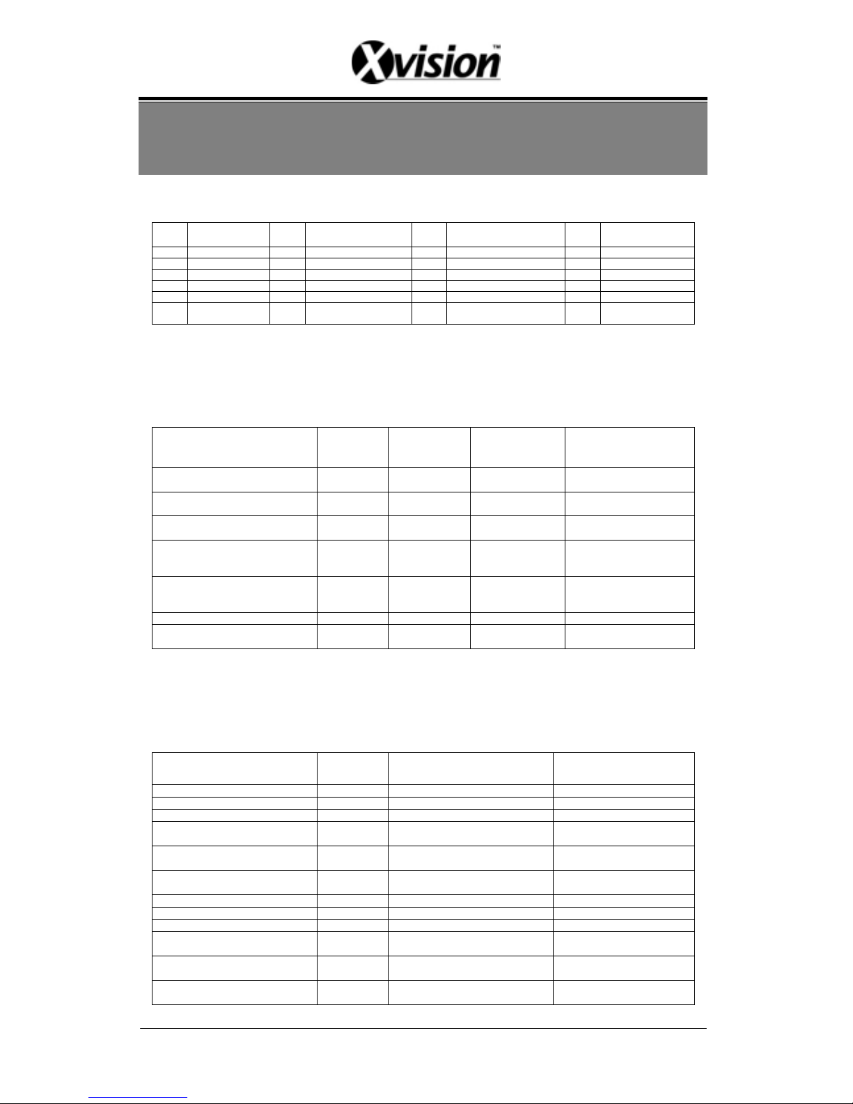
13.1 DB25 Alarm Input/Relay Output Definition
Pin Definition Pin Definition Pin Definition Pin Definition
1 ALARM 1 2 ALARM 2 3 ALARM 3 4 ALARM 4
5 GND 6 ALARM 5 7 ALARM 6 8 ALARM 7
9 ALARM 8 10 GND 11 ALARM 9 12 ALARM 10
13 ALARM 11 14 ALARM 12 15 GND 16 ALARM 13
17 ALARM 14 18 ALARM 15 19 ALARM 16 20 GND
21 RELAY
OUT-COM
22 RELAY OUT-N.C. 23 RELAY
OUT-N.O.
13.2 List of Tested Hard Disk Drive
Brand names listed below implies tested and suggested priority use. The product does
not guarantee problems due to specification change, and other brands unlisted does
not mean that it is incompatible.
Brand
(according to alphabetical order)
Capacity Part No. Serial No. Comment
HITACHI 500GB
HDS725050KL
AT80
P/N:0A31613
S/N:ZAG327DC
ATA/IDE 7200RPM
Made in Thailand
Maxtor 40GB
D740X-6L
MX6L040L2
051Z04
B2211J
Made in Singapore
Maxtor 80GB
E-H011-02-312
2
R29F2HGE
DiamondMax 16 ATA/133
Made in Singapore
Maxtor 80GB
E-H011-02-388
0
Y28DVEWC
DiamondMax Plus 9
ATA/133
Made in Singapore
Maxtor 120GB
E-H011-02-388
0
Y35E89XE
DiamondMax Plus 9
ATA/133
Made in Singapore
Seagate 4GB ST34321A VTF07041 Made in Malaysia
Western Digital 40GB
WD400EB-00JE
F0
WMAJA1636391 Made in Malaysia
13.3 List of Tested Compact Flash Card
Brand names listed below implies tested and suggested priority use. The product does
not guarantee problems due to specification change, and other brands unlisted does
not mean that it is incompatible.
Brand
(according to alphabetical order)
Capacity Serial No. Comment
ADATA 128MB 0410077-128
ADATA 256MB 0411073-256
ADATA 1GB 0411081-1GB
Apacer 64MB
P/N:86.20640.010
M/N:AP-CF06411
Made in Taiwan
Apacer 128MB
P/N:86.21280.150
M/N:AP-CF12811
Made in Taiwan
Apacer 256MB
P/N:86.22560.110
M/N:AP-CF25611
Made in Taiwan
SanDisk 64MB AB0308VH Made in China
SanDisk 256MB N/A
SanDisk 512MB N/A
Transcend 512MB
114231 0808 4050
63 512MCP 0515
45x
Transcend 1GB
109928 0595 4050
63 1BCP 0503
45x
Transcend 4GB
117152 0130 5690
VC 4BCP 0523
80x
Page 47
46
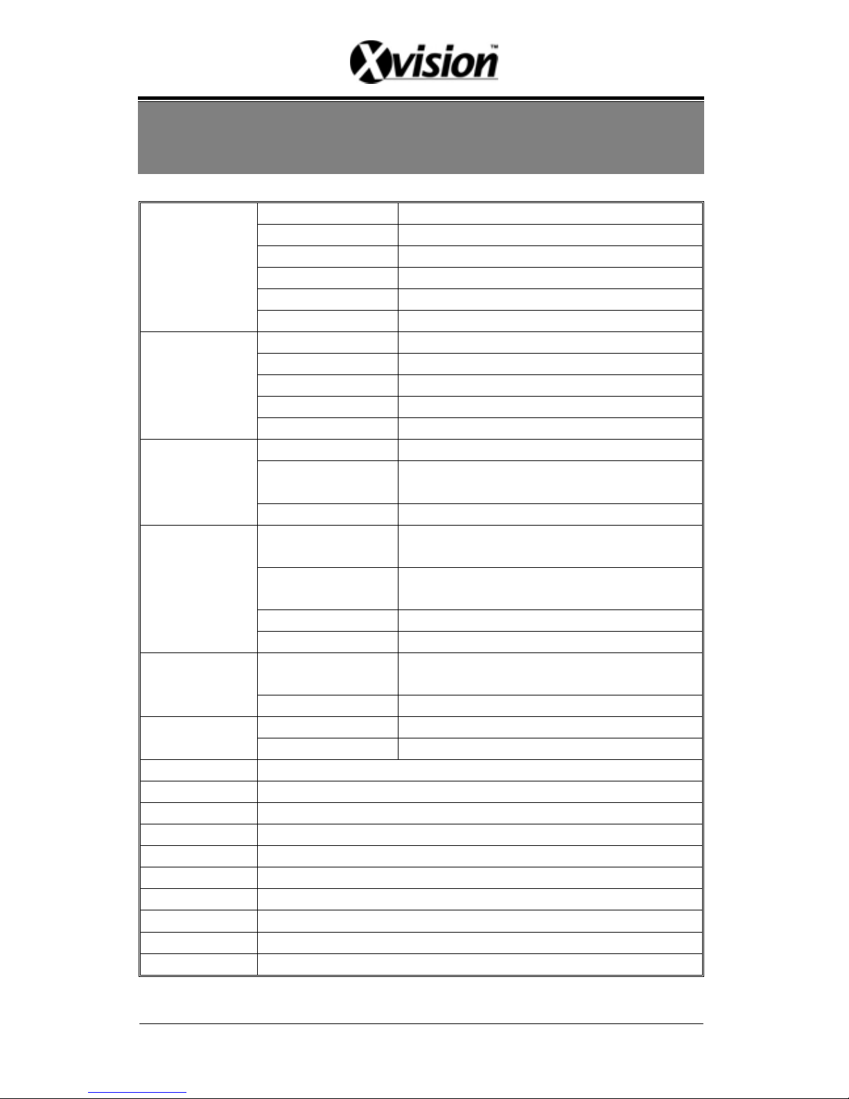
14. SPECIFICATION
Format NTSC / PAL Auto Detection
Video Loss Auto Detection
Codec MPEG4
Input 16 CH BNC (1.0 Vp-p. / 75 Ohms)
Main Display Output 1 CH BNC (1.0 Vp-p. / 75 Ohms)
Video
Spot Display Output 1 CH BNC (1.0 Vp-p. / 75 Ohms)
Input 1 CH RCA
Sampling Rate 8 KHz
Codec G.726
Output Bit Rate 32 Kbps
Audio
Output 2 CH RCA
Resolution 720 x 480 (NTSC), 720 x 576 (PAL)
Frame Rate
Max.: 240 fields/sec (8 CH mode)
Max.: 120 fields/ sec (16 CH mode)
Live
Mode Single / Quad / 9-Split / 16-Split/ Sequence
Resolution
NTSC: 352x240 / 704x240
PAL: 352x288 / 704x288
Frame Rate
NTSC: Max 60 IPS @352x240, Max 30 IPS @704x240
P AL: Max 50 IPS @352x288, Max 25 IPS @704x288
Quality Low / Medium / High
Record
Mode Manual / Alarm / Motion Detection / Continue
Speed
Normal / Pause / Fast Rewind (x32, x64) / Fast Forward
(x2,x4,x8,x16,x32,x64)
Play
Mode Single / Quad / 9-Split
Input 16 CH, N.C. / N.O.
Alarm
Output 1 CH, N.C. / N.O.
Storage 3.5”IDE HDD x 1 (Removable), Max. 500 GB, Fixed HDD (Optional)
Backup Type I CF Card x 1, ASF File Format
LED Indicators Alarm / Play / HDD / Record
OSD Language English / Traditional Chinese
Power Supply 12V / 4.2A
Power Adaptor AC 100~240 V Input, DC 12V / 4.2A Output
Dimension 430 (W) x 70 (H) x 316 (D) mm
Weight 3570 g (without HDD)
Storage Envir. 30 ~ 90% RH, 0℃ ~ 50℃ (32℉ ~ 122℉)
Operation Envir. 30 ~ 80% RH, 5 ~ 4℃ 0 (41 ~ 1℃℉04 )℉
Page 48
Network (optional)
Ethernet 10/ 100 BaseT Ethernet (RJ45)
Network
Protocol
TCP/ IP,HTTP,PPPoE,DNS,DDNS,
DHCP,SMTP
Format NTSC/ PAL Auto Detection
Video
Compression M-JPEG
Audio
Compression AC-97
Resolution Max. 640 x 480 (NTSC), 704 x 576 (PAL)
Display
Frame Rate Max. 20 fps
Resolution Max. 640 x 480 (NTSC), 704 x 576 (PAL)
Frame Rate Max. 20 fps
Quality Highest/ High/ Middle/ Low/ Lowest
Recording
Mode Manual
(Note: Design and specifications are subject to change without prior notice.)
47
Page 49

MEMO
48
 Loading...