

Page 1

Multi-Protocol
controller
keyboard
XTS-KBC-100
USER‘S MANUAL
Page 2
Warning
TO REDUCE THE RISK OF FIRE OR ELECTRIC SHOCK, DO NOT EXPOSE THIS PRODUCT TO
RAIN OR MOISTURE. DO NOT INSERT ANY METALLIC OBJECTS THROUGH THE VENTILATION
GRILLS OR OTHER OPENINGS ON T HE EQUIPM ENT.
FCC COMPLIANCE STATEMENT
FCC INFORMATION: THIS EQUIPMENT HAS BEEN TESTED AND FOUND TO COMPLY WITH THE LIMITS
FOR A CLASS A DIGITAL DEVICE, PURSUANT TO PART 15 OF THE FCC RULES. THESE LIMITS ARE
DESIGHEND TO PROVIDE REASONABLE PROTECTION AGAINST HAMRFUL INTERFERENCE WHEN THE
EQUIPMENT IS OPERATED IN A COMMERCIAL ENVIRONMENT. THIS EQUIPMENT GENERATES, USES,
AND CAN RADIATE RADIO FREQUENCY ENGERGY AND IF NOT INSTALLED AND USED IN ACCORDANCE
WITH THE INSTRUCTION MANUAL, MAY CAUSE HARMFUL INTERFERENCE TO RADIO
COMMUNICATIONS. OPERATION OF THIS EQUIPMENT IN A RESIDENTIAL AREA IS LIKELY TO CAUSE
HARMFUL INTERFERENCE IN WHICH CASE THE USER WILL BE REQUIRED TO CORRECT THE
INTERFERENCE AT HIS OWN EXPENSE.
CAUTION: CHANGES OR MODIFICATIONS NOT EXPRESSLY APPROVED BY THE PARTY RESPONSIBLE
FOR COMPLIANCE COULD VOID THE USERS‘S AUTHORITY TO OPERATE THE EQUIPMENT.
CE COMPLIANCE STATEMENT
WARNING: THIS IS A CLASS A PRODUCT. IN A DOMESTIC ENVIRONMENT THIS PRODUCT MAY CAUSE
RADIO INTERFERENCE IN WHICH CASE THE USER MAY BE REQUIRED TO TAKE ADEQUATE
MEASURES.
This symbol indicates that there are important
operating and maintenance instructions in the
literature accompanying this unit.
This symbol indicates that dangerous voltage
constituting a risk of electric shock is present within
this unit.
CAUTION: TO REDUCE THE RISK OF
ELECTRIC SHOCK, DO NOT
REMOVE COVER ( OR BACK). NO
USER SERVICEABLE PARTS INSIDE.
REFER SERVICING TO QUALIFIED
SERVICE PERSONNEL.
1
Page 3

Contents
Warning............................................................................................... 1
Contents.............................................................................................. 2
Introduction..........................................................................................3
Installation........................................................................................... 4
Stand-Alone mode...............................................................................5
RS-485 network...................................................................................6
Working with the keyboard.................................................................. 7
Operating.............................................................................................8
PTZ-operation......................................................................................9
Cruising functions................................................................................10
Sequence setup...................................................................................11
Viewing control.................................................................................... 12
Keyboard setup menu..........................................................................13
Keyboard Setup / Auxiliary Functions..................................................14
Key- Function Overview.......................................................................15
Specification........................................................................................ 16
2
Page 4

INTRODUCTION
• 3-Axis controlling stick provides max. usability and performance( Pan/ Tilt / Zoom) in 1-hand-
operation.
• Variable, step-less controlling speed for PTZ, easy for manual object tracking.
• Large-sized, high-contrast LCD display with green back-light for a comfortable overvie wand
detailed status report.
• Easy access: Hot-keys for most frequently used PTZ function.
• Programming and call of presets, tour and pan-swing.
• Direct parameter setup for accessing additional camera / speed-domefunctions ( e.g. Flip
images, switching day/night mode..etc).
• Controls up to 255 Speed-Domes or PTZ Devices from 1 keyboard.
• Master / Slave operating mode for multiple control ( 2 modes).
• Built-In configuration menu for keyboard setup.
• Double-featured keypad inputs ( by pressed longer than 3 sec.)
Features
3
The keyboard Intelligent, multiple-protocol keyboard controller is designed for operator t o control
speed-domes, zoom camera and PTZ device. it‘s ergonomic concept and user -friendly 3-axis
controlling stick provide its operator max. usability and performance. With this keyboard
controller, you can also easily activate and programming presets, tou r s and memo r i zed persona l
references on PTZ devices. It can also be used to access addtional devices setting via short key,
such as manual / auto iris, day&night mode changing and etc.
The large-sized LCD is used to display current status, and as well as to pr o v ide a menu-s ystem
for setting operational parameter of the keyboard. It is equipment with a gr een back- ligh t fo r
operation under different conditions.
This keyboard contains 2 RS-485 connectors for operation in Master- or Slave-mode, which can
be used in multiple-control environment with selectable privilege.
• Multiple-Protocol support in each channel.(XTS, XTS-2, B01, Pelco D, Pelco P).
Page 5
INSTALLATION
Unpacking
Please unpack the equipment and make sure all listed itemsand accessoriesare includedin the box:
Keyboard controller 1
RJ-11 RS485 connection cable 1
Instruction manual 1
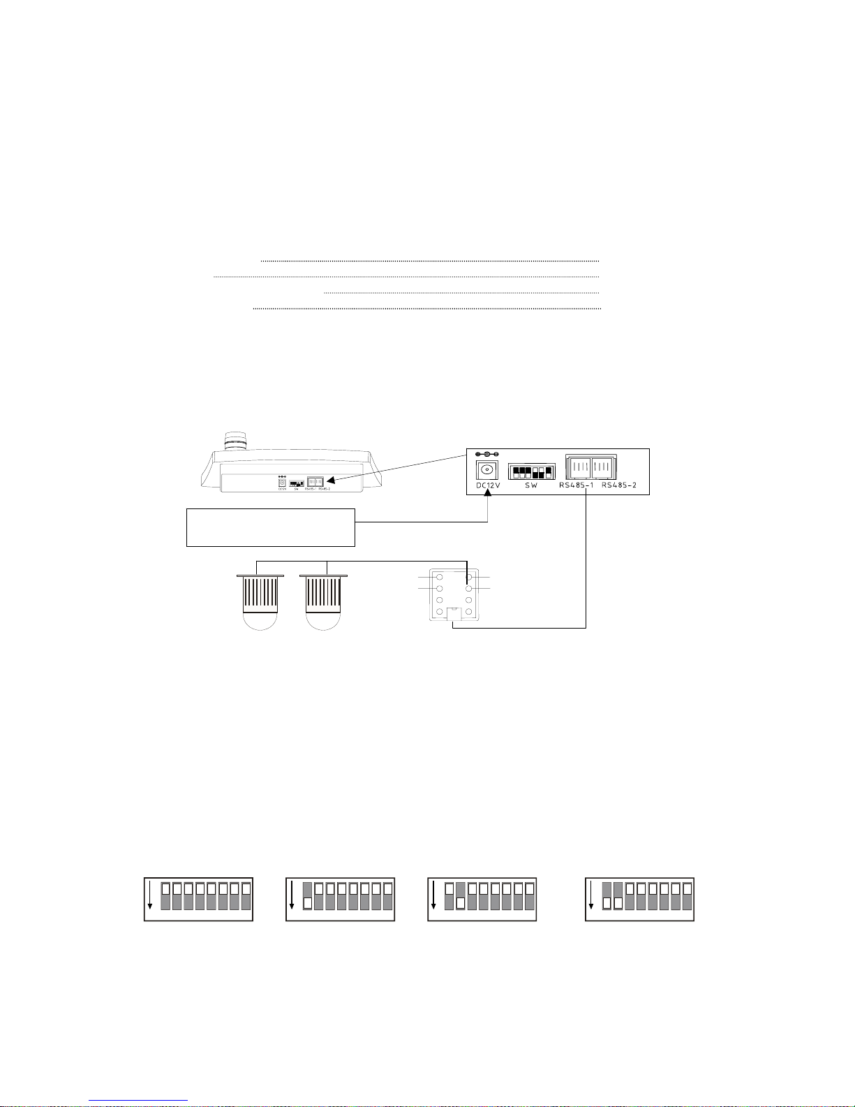
There are 2 RJ-11 connectors on the keyboard for RS-485 cont rol:
RS485-1( Master port) line connector is normally used for Speed-Dome or othe r PTZ-device wi th RSFor further information regarding wiring, please refer to the operation manual of the connected PTZ
devices.
Keyboard ID
Some PTZ devices might require the setup of keyboard’s ID ( sender ID), you can set the ID by
Connection
ID is 0
( default setting)
ON
1 2 3 4 5 6 7 8
ON
1 2 3 4 5 6 7 8
ON
1 2 3 4 5 6 7 8
ON
1 2 3 4 5 6 7 8
ID is 1 ID is2 ID is3
9 ~12V Power supply
500mA
Master port Slave port
R
RS485+
Bl
RS485-
C
GND
Y
GND
RJ11 cable
Speed dome /
PTZ devices
4
Chunk box
1
Chunk box
485 connector. Indicator for chunk box wir ing: Red:RS485+, Black: RS485 -, Green & Yellow: Ground.
changing the DIP-swit ch of no.1 and 2 on the back pane l of the keyboard. The default setting is “0 ”
Page 6
STAND-ALONE
Stand-Alone / Master-Slave operation
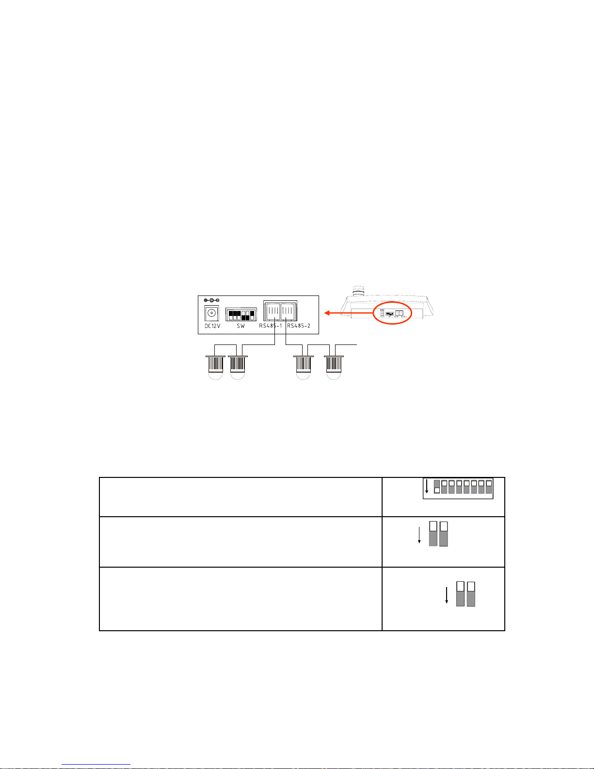
This keyboard support 2 operation mode for max. 255 devices connected. Depends on the
requirement, you can setup the keyboard for stand-alone or master/ Slave mode:
1. Stand-Alone mode:
Only 1 controller keyboard is used for all connected devices. In this operation mode, both
connectors ( RS-485-1 and RS-485-2) can beused. Depends on the wiring type, you might need to
active the termination of the keyboard for the RS-485 chain. The connection
Setup the Stand-Alone mode:
ON
1 2 3 4 5 6 7 8
2. Depends on the wiring, you might need to activate the on-board
termination of the keyboard for RS-485 connection chain. Use DIPswitch no. 7 (port RS-485-1) and no. 8 (port RS-485-2) for enable or
disable the on-board termination.
1. On the back panel, set the DIP-Switch no. 3 and no. 4 to state „OFF“
SettingSteps:
ON
3 4
ON
7 8
RS-485 Chain no.1 RS-485 Chain no.2
Up to
32 devices
....
...
Termination
5
Page 7
MASTER/SLAVE MODE
(optional function)
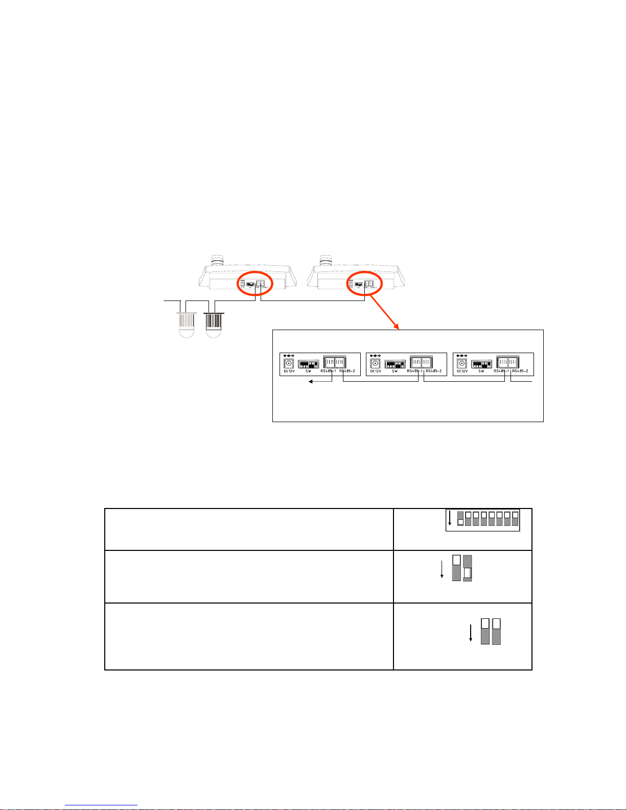
2. Master / Slave mode:
For certain installations, multiple-control structure might be required. You can setup the keyboard to
Master / Slave mode in order to work with more than 1 keyboard simultanously. In this operation
mode, all keyboards have to be connected in a chain, with RS-485-1 for output and RS-485-2 as
input ports. The keyboard that is nearst to the devices has the highest priority.
How to setup Mater/Slave mode:
Keyboard 1 Keyboard 2
Other keyboard
or termination
To PTZ or speed
dome devices
Up to
32 devices ...
ON
1 2 3 4 5 6 7 8
2. Depends on the wiring, you might need to activate the on-board
termination of the keyboard for RS-485 connection chain. Use DIPswitch no. 7 (port RS-485-1) and no. 8 (port RS-485-2) for enable or
disable the on-board termination.
1. On the back panel, set the DIP-Switch no. 3 to state „OFF and no. 4
to state „ON“
SettingSteps:
ON
3 4
ON
7 8
6
Page 8
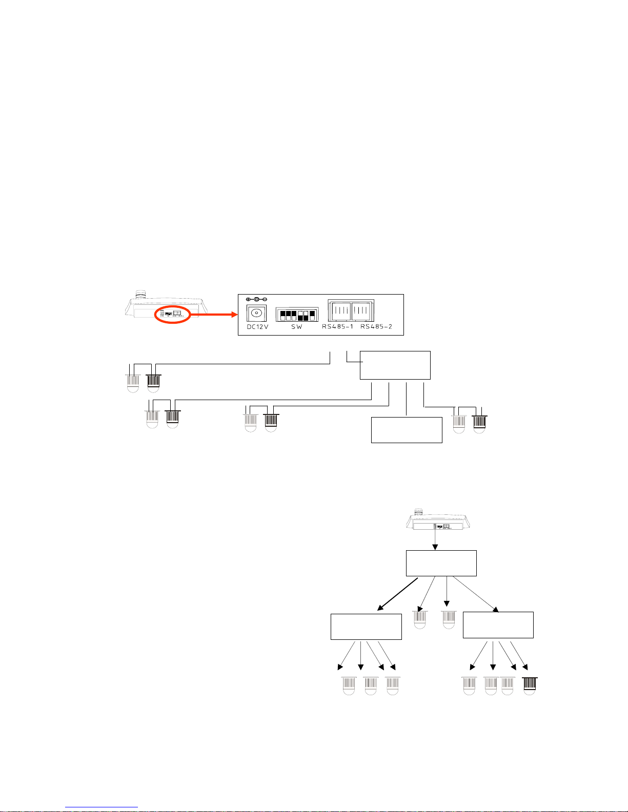
RS-485 NETWORK
Multiple connections to a single port
Depends on the installation environment, you may have different RS-485 chains connected as a
„network“. In order to let your keyboard working properly, please refer to the examples given
bellow:
You can connect max. 3 RS485-chains to each port ( in Master / Slave mode: connect only to RS485-1 port.) For more chains, you need to use a RS-485-Distributor to expand the connectivity
( Please contact technical personnel or sales representatives for purchasing and further
information). The total number of connected devices shall notexceed 32.
* Depends on cable-quality and environment, the wiring length might be shorter than specified.
4-way RS-485
Distributor
RS-485 chain no.1, up to 1000 m*
RS-485
Distributor
Max32 devices
Star- / Tree- Connection network
Basically, a star connection is similar to a
multiple-connection. Each RS-485 port on the
keyboard can handle up to 3 chains ( totally 6
chains in stand-alone mode, Only 3 chains in
Master/ Slave operation mode). In case more
chains are present, you might need to use RS485 distributors. Each chain can be expanded
with RS-485 distributor ( tree-connection). The
total number of connected PTZ devices shall
not be more than 32.
RS-485-chain no. 3
up to 1000 m*
RS-485-chain no. 4
up to 1000 m*
Further RS-485-chains through
2nd RS-485 distributor,
with each chain length up to 1000 m*
RS-485
Distributor
RS-485
Distributor
RS-485 chains
7
RS-485
Distributor
OR
Page 9
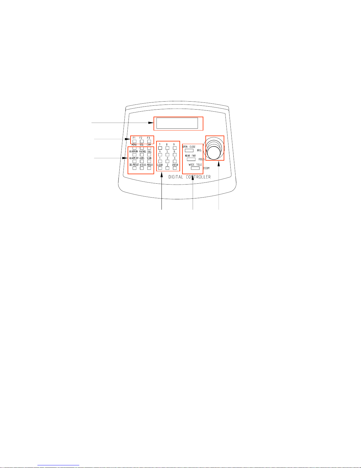
WORKING WITH KEYBOARD
Front panel
1
2
3
45
6
1. Status & Menu Display: LC-Display with back-light shows current keyboard setting, status and
configuration menu.
2. Extended Function keys: activate extended functions, such as extended camera settings and setup
3. Operation keys: Performing default operations such as presets, sequence, camera selection etc.
4. Digit pad: Numeric input for parameter setup.
5. Camera operation keys: Manual iris and focus control, secondary zoom-control button.
6. 3-axis PTZ-stick (KB3A only) for pan, tilt and zoom: PTZ control.
8
Note:
- the default operation keys canprovide a secondary function by keep on pressing longer then 3 seconds.
Please refer to the chapters for detailed description
- Combined with the operation keys, you might need the digit pad for parameter input. Press [ENTER] for
input confirmation and [CLEAR] for cancellation.
Page 10
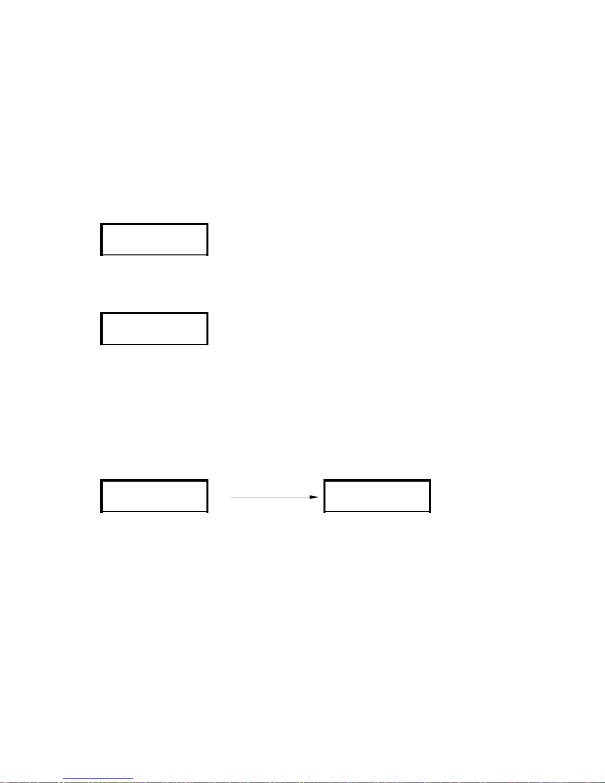
OPERATING
Turning on the keyboard
This keyboard can control up to 255 connected devices. You canselect any one by pressing
[CAM] + [ID]+ [ENTER]
9
VERSION V2.06
LCD shows the keyboard‘s firmware version
and manufacturing date
After plugging in the power, the keyboard will start the initialization and self-test. The LC-Display
will show following message: (for about 2 sec.)
Master
LCD shows the current controlling protocol
and selected device ID. „Master“ indicates
that the keyboard is currently set to „Mastermode“
After about 2 seconds, the keyboard finishes the initializationand is ready to operate :
Select a device
CAM [ID]
[ID] can be any number between 1 –255.Please ensure that every device connected to the
keyboard has a valid and unique ID.For setting up the ID, please refer to the operating manual of
each device.
Master
To setup the keyboard in other controlling protocol, please refer to the section „Keyboard setup“for
details.
XTS-2 CAM:001
2009 / 11 / 05
XTS-2 CAM:001
XTS-2 CAM:[ID]
Page 11
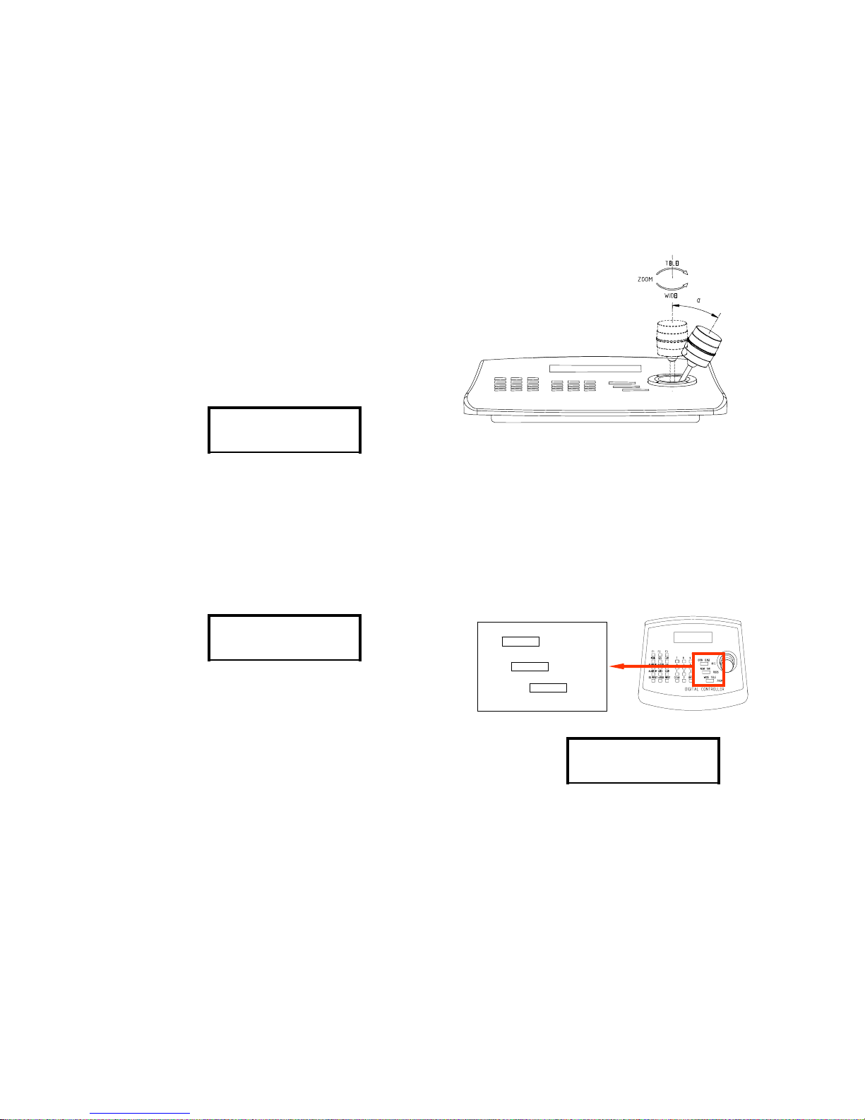
PTZ-CONTROL
Secondary zoom control and camera operation
speed (depends on the angle the stick has been moved).
Move the stick to up or down for the tilt-operation,
and move left and right for pan-action. For zooming,
only)
While operating, the LCD will show the action
which is currently performed. E.g the stick is on
up-right:
Up Right
Using the PTZ-Stick
OPEN CLOSE
NEAR FAR
WIDE TELE
IRIS
FOCUS
ZOOM
Beside the stick, the keyboard provids an additional button to control the zoom action, which can be
used simultaneously with the PTZ-stick. By pressing the zoom-buttonthe LCD shows the performed
action:
Most PTZ-devices or Speed-dome camera operate in
Auto-Focus and Auto-Iris mode by default. In case you
need to work manually, please follow the steps below:
During the PTZ-operation, Camera will change to auto-focusing for providing clear pictures.
WIDE
Manual Iris: press „OPEN“ button for opening the camera
iris( brighter) and „close“ fo r closing it ( darker). To switch back to
Auto-Iris mode, please press the button „A. IRIS“ on the left side of
the keyboard panel.
Manual Focus : press „NEAR“ and „FAR“ buttons for fine-tuning the focusing. For switching back to the
Auto-Focus mode, just press the button „A. Focus“ on the left side of the keyboard panel. Operation on
the PTZ-Stick will force the camera switching to Auto-Focus mode.
OPEN
E.g: status while „IRIS close“ is
pressed
Note: some camera models need to enter „manual mode“ at first, before manual adjusting on the iris and focus manually. Pleaserefer
to their operating manuals for further information.
10
You can use the PTZ-Stick to perform pan, tilt and zoom (KB3A only) operation with various
please turn it to left (wide) or right( tele). (KB3A
XTS-2 CAM:001
XTS-2 CAM:001
XTS-2 CAM:001
Page 12
PRESET / CRUISING TRACKS
Presets
Sequential cruising, also known as „tour-function“: It runs through pre-defined points with individual speed
and duration settings. These points can be defined with the preset-positions:
Save a preset-position: move the PTZ device to desired position, then press
Preset: N
[PRESET] + [N]+ [ENTER]
number between 0 and 255.
Call a preset-position: to call a preset, press
[CALL] + [N]+ [ENTER]
The PTZ device will movethe camera to the
requested preset position.
Delete a preset-position: for deleting a saved preset, press
[DelPreset] + [N]+ [ENTER ]
Sequence ( tour)
Most Speed-Dome camera and PTZ-devices supports memorizing preset positions. You can use this
keyboard to save and call the saved presets.
1
2
3
4
5
Preset points
Sequence 1
Call: N
DelPreset: N
Note: In order to setup the points for a sequence, youmight need to setup the preset position at first.
This keyboard supports the setup of max. 4 sequence with 16 points for each. Some PTZ-Device or
Speed-Dome camera may not support this function. For details please refer to the operating manual for
further details.
Save a sequence:
enter the sequence setup by pressing [SEQ] longer than 3 seconds. LCD will
show following status:
SET SEQ n
Now enter the sequence ID (1 to 4) and press [ENTER] to enterthe edit
mode
n indicates the sequence which currently is being edited, x shows the point the
number of presets contained in this sequence( max. 16).
EDIT SEQ
n SEQ x Preset
11
[N] indicatesthe current preset and can be any XTS-2 CAM:001
XTS-2 CAM:001
XTS-2 CAM:001
XTS-2 CAM:001
Page 13
SEQUENCE/ SCAN/ PATROL
No. Pre Spd Time
01 n1 n2 n3
No.: index of the points, max. 16
Pre.: Preset-position assigned for this point, from 1 to 255
Spd: The cruising speed to this point, 1 (lowest ) to 8 (highest speed)
Time: duration of the stay in seconds (1 to 99)
The cursor now is pointed to n1 ( preset), Use[number]+[Enter] to assign a preset to this point. The
number can be from 1 to 255. After assigning, the cursor will move automatically to n2 (speed). Use
[FAR] or [NEAR] to move the cursor from 1 parameter to another. For moving to next point, please
press [TELE] or [WIDE].
After the setting for all points is done, youneed to press [SEQ] ( less than 3 sec) to save the sequence
and turn back to the main menu:
No. Pre Spd Time
Save, waiting.......
If any point of a sequence has been assigned with 0 ( means no preset),
then all the points after this one will be set to 0.( deleting)
Activate a stored sequence:
[SEQ] + [N]+ [ENTER]
SEQ n
[N] can be any number between 1 to 4, please note not to press
[SEQ] longer than 3 sec.
LCD will show the calling of sequence no. N has beenexecuted.
Scan
Activate Scan:
[SCAN] + n + [ENTER]
SCAN n
LCD shows the activation of scan
In order to work with the Scan-Function, you might need to
enter the device‘s setup-menu and define the scan-points
Patrol
Set Patrol: Press the key [PATROL] for long than 3 sec. for entering the patrol setup mode, then
press patrol number ( 1 to 4) setup. Use [ENTER] for confirmation.
[PATROL] ( 3 sec.) + n + [ENTER]
SET Patrol n
Note: You can only setup the patrol-function on device
which support this feature.
Activate a patrol-track:
[PATROL] + n + [ENTER]
Patrol n
12
Note: which is to call learning (pattern scan), the actual command
code is Call + (70 + n) + Enter , n means Learning No .
Note: which is to call SEQ(track), the actual command code is
Preset + (70 + n) + Enter , n means Track No.
※PATROL + n + Enter and SEQ + n + Enter are eff e ctive to XTS,XTS2,PelcoD and Pelc oPprotocol.
※PATROL + n + Enter and SEQ + n + E n t e r are o n ly q ui c k calls o f le arni n g (pattern scan) and SEQ;
XTS-2 CAM:001
XTS-2 CAM:001
XTS-2 CAM:001
XTS-2 CAM:001
the corresponding setting must be done by the dome camera and PTZ menu.
Page 14
FOCUS/ IRIS CONTROL
Automatic and manual Focusing:
This keyboard provides function keys for accessing zooming, focusing and iris control directly. It is
handy to operate them through these keys. In some protocols you might need to enter the manual mode
at first before operating.
Adjusting the focus of the camera manually. Now
the camera will enter the manual mode
automatically
FAR
FAR
NEAR
Near
A. Focus
With this key, the camera will enter the Auto-Focus
mode.
Automatic and manual Iris:
AdjustingtheIris stateof thecamera. Use[OPEN]
to open the camera‘s iris in a dark enviroment, and
use [CLOSE] for zone with more lightning.
OPEN
OPEN
CLOSE
CLOSE
A. IRIS
Press this key for entring the auto-iris mode.
Secondary ´Zooming function key
Beside the controlling Stick, you can also use these
keys for the zoom-function.
TELE
TELE
WIDE
WIDE
13
XTS-2 CAM:001 XTS-2 CAM:001
XTS-2 CAM:001 XTS-2 CAM:001
XTS-2 CAM:001 XTS-2 CAM:001
Page 15
KEYBOARD MENU
1. Protocol setup
You can change the setting of keyboard from the setup menu. For entering setup, please press
the key [Menu] longer than 3 seconds. Use [TELE] for moving to next item, and [WIDE] to move
backwards. Press [ENTER] for confirmation. For exiting please press the [MENU]-key, all the
changes on settings will be stored.
* Depends on cable-quality and environment, the wiring length might be shorter than specified.
The keyboard supports multiple controlling protocol, for operation with the connected devices, you need to
setup up the protocol correctly. Please refer to the operation instruction of the manufacturer. Please press
[FAR] or [NEAR] for moving to next protocol. For exiting, please press [Menu]
1: Protocol ÅÆ
This keyboard support the call-up of the OSD menu of speed dome by pressing the short-cut key [MENU].
In order to make it functioning correctly, you need to set up for every connected device. Once the [MEN U]
key is setup, the keyboard will assign the function keys with correct value automatically:
[Patrol], [A.Iris], [A.Focus], [Alarm On], [Alarm Off] ( depends on PTZ model)
For change the camera ID, please press [FAR] and [NEAR]. Please use [ENTER] to move to the next
option. Following options are supported:
OSD function.
1: Protocol ÅÆ
Pelco P 9600
1: Protocol ÅÆ 1: Protocol ÅÆ
2. Demo menu code
2: Demo menu code
Cam001: Call 8
device‘s OSD menu by pressing [MENU]
2. „Call 95“: Please choose this option for the another speed-domes and PTZ devices:
2: Demo menu code
Cam002: Call 95
E.g: the camera device no. 2 uses normally the key-combination [CALL]+ 95 for
entering the OSD menu. Choose this option will enable the entering of OSD by
pressing the key [MENU]
2: Demo menu code
14
1: Protocol ÅÆ
Pelco D 9600
1: Protocol ÅÆ
1: Protocol ÅÆ
Pelco D 1200
1: Protocol ÅÆ
XTS
1: Protocol ÅÆ
ALEC 4800
1: Protocol ÅÆ
ALEC 9600
1: Protocol ÅÆ
LG MULTIX 9600
1: Protocol ÅÆ 1: Protocol ÅÆ 1: Protocol ÅÆ 1: Protocol ÅÆ
B01 Pelco P 4800 Pelco D Pelco D 4800
XTS-2 2400 XTS-2 4800 XTS-2 9600 XTS-2 19. 2K
1. „Call 8“: Please choose this option for the XTS speed-domes and PTZ devices, which support the
E.g: the camera device no. 1 is a XTS-SD26XDN-WP speed dome ( set to work with
XTS-2 protocol). The selection of the option „call 8“ will enable entering the
3. „ None“: This option indicates that the current device does not support OSD Menu
Cam003: None
Page 16
AUXILIARY FUNCTIONS
3. LCD Backlight
The LC Display supports the backpanel – lightning, which can be helpful in some working environments.
3. LCD Light ÅÆ
ON
Use [FAR], [NEAR] to select ON / OFF, use [MENU] for exiting.
4. Key-Tester
This keyboard provides a key-tester function for debugging.
4. Key Press testÅÆ
Press: <KEY>
Enter the Key-Tester and the key board starts waiting for operator‘s
input.
AUXILIARY FUNCTIONS
For accessing the auxiliary functions, such as camera internal setting parameter or brush, you can use the
key-combination [F1] + n + [ENTER], where n indicates the function code described in page 17.
F1 ON n
For acivting any on the function, please press [F1] for longer than 3
seconds. This LCDisplay will display „F1 ON n “
To deactivate, you need just press [F1] once and enter the
function code
F1 OFF n
F1 ON n
e.g: [F1]+12+[Enter] for wash
15
XTS-2 CAM: 001
XTS-2 CAM: 001
XTS-2 CAM: 001
Page 17

SUMMARY-KEY FUNCTION
**Starts Auto-Iris mode][A. IRIS]21.
**Starts Auto-Focus mode[A. FOCUS]20.
Focusing Near (starting manual focus mode)[NEAR]19.
Focusing Far (starting manual focus mode)[FAR]18
Zoom-In[TELE]17.
Zoom-Out[WIDE]16.
Close Iris(Enters manual iris mode)[CLOSE]15.
Open Iris (Enters manual iris mode)[OPEN]14.
Confirmation of selected operation. [ENTER]13.
Clear current keyboard input[CLEAR]12.
Number Input[0] – [9]11.
0 – 255 Select PTZ-Device No. X[CAM] + X + [ENTER]10.
Start Scan[SCAN]9.
0 – 255Delete Preset No. X[DEL Preset] + X +
[ENTER]
8.
0 – 255Set preset point no. X[PRESET] + X + [ENTER]7.
0 – 255Move to preset No. X[CALL] + X + [Enter]6.
Disable alarm function[ALARM OFF]5.
Enter Keyboard setup
menu
Enter device OSD
Menu
[MENU]3.
*,**0 – 16Auxiliary Function
On
Auxiliary Function
Off
[F1] + X + [ENTER]2
no. X
no. X
x –
Range
RemarkPress 3 sec.Press onceKey-CombinationNo.
** May not work with some speed-domes or PTZ-devices
16
1 [SEQ] + X + [ENTER] Activate Sequence Setup Sequence 1 – 4 *,**
4. [ALARM ON] Enable alarm function
* May not functioning with protocols other tha B01, XTS, XTS-2
Page 18

ADDITIONAL FUNCTION/ SPECIFICATION
300mm x 230mm x 110mmDimension
Under 90%Humidity
-5°C to 40°CTemperature
9V – 12V DC, 500mAPower supply
Max. 1200 m (0.5mm Ø wire)Wiring distance
2400/ 4800/ 9600 Baud, Protocol dependentBaud rate
EIA / RS-485, Half-DuplexTransmission / receiver
All Rights reserved.
Technical specification might be modified without prior notice.
Specification
Auxiliary Functions
OffOnA uxiliaryLight16
OffOnLight15
OffOnLenspower supply14
OffOnBrush13
Decorder
functions.
OffOnWash12
Black-WhiteColorColor / Black-White image11
NormalFreezeFreeze image10
NormalMirrorMirror image9
ManualAutomaticWhite Balance8
ManualAutomaticIris7
ManualAutomaticFocusing6
Reserved5
OffOnDigital Zoom function4
OffOnCam er a Dis p l a y3
OffOnLow Illumination mode ( night mode)2
OffOnBack light conpensation1
OffOnCam er a P o wer0
Press 3 Sec. Press onceFunction NameX
17
 Loading...