

Page 1

1
Acknowledgement!
Thank you for purchasing our car DVD player! In order to use this system properly, please
read this manual before using it. Keep this manual for the future reference.
1. Warning:
Keep the disc entry clean. You should clean it immediately if there is dust. Disc with dust
must be cleaned by clean soft cloth before putting into the machine, otherwise, the dust will
be taken into the machine together with the disc from the entry, which may influence the
drive of the machine, and cause the entrance problems of the disc. The dust may dirty the
laser head resulting in the poor read or failed read of the disc.
Notes for installation
This DVD play is designed for operation on 12V-14V DC negative ground system only.
Make sure your car is fit for this negative ground system before installing the DVD.
Remove the [-] power supply of the battery ground wire before installing this DVD, so as to
decrease the rate of damaging the machine because of short circuit.
Follow the wire color on the installation manual to connect the line. Wrong connection may
cause the machine malfunctions or damage the car electrical system.
Lead wire ( - ) of speaker must connect to the ( - ) terminal of the speaker. Do not connect it
to the car or other lines.
Do not block the vent or louver board to avoid the fire caused by the overheating inside the
machine.
When you start to use the DVD after the installation completed (Including after you have
changed the battery), you should use a small round tool to press the RES button on the panel
to restore the system to the initial settings.
Page 2

2
2. Connecting guide
ONE DIN Connection Guide
1. Rear right audio output
2. Rear left audio output
3. Front right audio output
4. Front left audio output
5. Right audio output
6. Left audio output
7. SUB-WOOF
8. Rear cam in
9. Video input
10. Radio antenna
11. Video Output 1
12. GPS antenna
13. DTV Antenna
15. Power Supply
16. Power Ground
17. ACC car keys switch
18. Brake-Con
19. BACK-CON
20. Radio antenna connector
21. Front left speaker
22. Front right speaker
23. Rear left speaker
24. Rear right speaker
25. KEY 1
26. KEY2
27. Headlight Control line
28. GND
Page 3

3
TWO DIN Connection Guide
1. Rear right audio output
2. Rear left audio output
3. Front right audio output
4. Front left audio output
5. right audio output
6. Left audio output
7. SUB-WOOF
8. Video input
9. ILLUNI
10. Radio antenna
11. TV Antenna
12. GPS antenna
13. DTV antenna
14. IPOD
15. Power supply
16. Power Ground
17. ACC car keys switch
18. BRAKE-CON
19. BACK-CON
20. Radio antenna connector
21. Front left speaker
22. Front right speaker
23. Rear left speaker
24. Rear right speaker
25. key 1
26. Key 2
27. rear cam input
28. Video output 1
29. Video output 2
Page 4

4
Special prompt:
1. ILLUMI: Connection head lamp headlamp power supply positive electricity
2. PARKING: Connection hand brake grounding
3. REVERSE-IN: Connection Back-draft firing line
4. B+: Connection automobile level positive electricity
5. ACC: Connection automobile vehicle key firing line
6. GND: Connection automobile level negative wire
7. P-CNTR: Connection external connection power amplifier ACC
8. Key1, key2: The steering wheel pilot wire, cannot receive a telegram the source, with
original vehicle against coil data line connection
Note: To keep pictures during the driving, connect the Break-in control line
(pink) to GND.
3. One Din Mounting Dimension
1. Pause
2. Repeat
3. Random
4. Stop
5. Down Slide
6. Up Slide
7. IPOD Slot
8. Aux in
9. Eject
10. Remote control Sensor
11. MIC
12. SD card Slot
13. USB port
14. Tuning/Selecting Tracks
15. Tuning/Selecting Tracks
16. Clock
17. Band
18. Reset button
19. Volume adjustment
20. Mute button
21. Open Screen
22. Power
Page 5

5
4. Two Din Mounting Dimension
Diagram of panel 01
1. MIC
2. Power ON/OFF
3. Mute
4. VOL-
5. VOL+
6. USB Port
7. LCD Touch screen
8. IR Receiver
9. Down Slide
10. Up Slide
11. Eject
12. Reset
Diagram of panel 02
1. Power ON/OFF
2. MODE
3. IR RECEIVER
4. LCD Touch Screen
5. Down Slide
6. Select
7. UP Slide
8. Reset
9. Eject
10. USB Port
Diagram of panel 03
1. LCD Touch Screen
2. IR Receiver
3. Power ON/OFF
4. SEL
5. VOL-
6. VOL+
7. UP Slide
8. Down Slide
9. Eject
10. MUTE
11. Reset
12. USB Port
Page 6

6
Diagram of panel 04
1. MIC
2. Reset
3. IR Receiver
4. Power ON/OFF
5. MUTE
6. LCD Touch Screen
7. VOL+
8. VOL-
9. SRC
10. Down Slide
11. UP Slide
12. Band
13. Eject
14. USB Port
Diagram of panel 05
1. Power ON/OFF
2. MIC
3. SEL
4. Reset
5. VOL-
6. VOL+
7. MUTE
8. LCD Touch Screen
9. Band
10. Down Slide
11. UP Slide
12. IR Receiver
13. Eject
14. USB Port
Diagram of panel 06
1. Power ON/OFF
2. LCD Touch Screen
3. Previous
4. Next
5. UP Slide
6. SEL
7. Down Slide
8. VOL-
9. VOL+
10. Eject
11. MUTE
Page 7

7
Diagram of panel 07(6.2 inch Fixed Panel)
1. Reset
2. Power/Mode
3. Mute
4. SD/GPS/USB slot
5. Aux in
6. MIC
7. Eject
8. SEL
9. Volume+
10. Volume-
Diagram of panel 08(6.2 inch Fixed Panel)
1. Reset
2. Eject
3. USB port
4. Band
5. Power/Mode
6. Volume+/-
7. SEL
8. GPS/SD slot
9. AUX in
10. MIC
Diagram of panel 09(6.2 inch Fixed Panel)
1. Power
2. GPS slot
3. MIC
4. Mute
5. GPS button
6. Menu
7. Set button
8. Volume+/-/Pause
9. USB port
10. TUNE button
11. SEL
12. TV button
13. DVD button
14. Band
15. Reset
16. SD card slot
17. Eject
Page 8

8
Diagram of panel 10(6.2 inch Fixed Panel)
1. MIC
2. GPS button
3. Mute
4. Volume+/-
5. Tuning/Selecting Tracks
6. Tuning/Selecting Tracks
7. AUX in
8. Eject
9. DVD button
10. SD card slot
11. USB port
12. GPS card slot
13. Band
14. Reset
5. Contents:
1. Warning……………………………………………………………………….1
2. Connecting guide…………………………………………………………...2-4
3. One Din Mounting Dimension………………………………………………..4
4. Two Din Mounting Dimension………………………………………..….....5-8
5. Contents………………………………………………………………..……8
6. Special Features………………………………………………………….…9-10
7. Main Menu…………………………………………………………………..11
8. General Setup……………………………………………………...……...11-15
9. Radio Mode………………………………………………………...….…15-17
10. DVD/SD/MMC/USB Operations……………………………..….……..17-19
11. TV mode………………………………………………………………....19-20
12. GPS Navigation Operation…………………………………….….....…..20-22
13. Bluetooth Mode…………………………………...……………….……22-24
14. IPod Operating Mode………………………………………………..…..24-25
15. AUX mode……………………………………………………….….……...25
16. System setup Menu………………………………………………….…..25-28
17. Remote Control………………………………………………….….…...….29
18. Troubleshooting……………………………………………………...….….30
19. Specifications………………………………………………………….……31
Page 9

9
6. Special Features:
※Three-Dimensional Cartoon Button Menu
Picture1
Picture 1:In the state of boot, you can slid panel left, right, up and down freely just only by your finger,
It would forward to the directions as the arrow shows on the figures, the main menu would revolve to the
directions that you slid.
※ Moving Icons Freely On the Main interface
Picture 2
Picture 2: You can move the icon freely on the main interface.
Step1: Looking picture 1, it shows all the icon buttons on the main interface when power on.
Page 10

10
Step2: You can move the icon freely to another position. Such as picture 2.【IPOD】Icon is
moved to the position of 【SD】Icon. You also can move the under small Icon to the up
position, It shows the icon button will bigger than before.
Step3: Looking picture 3, The position of 【SD】icon and 【IPOD】Icon is moved done.
※ Pictures-in-picture
A
1. In the mode of GPS, You can return to main interface by touch icon 1.
2. You can change the conditions among PIP1*, PIP2*, and PIP off by touch Icon2,
Please look at picture A, Under PIP1*State, The picture will show one quarter of GUI on
the interface. Under PIP2*state, The picture will show half of GUI on the interface(Picture
B). You can touch the direction of the screen to move them freely. Under PIP off state, The
picture will closed (Picture C).
B C
3. When you need lock the picture by touch Icon3.
Page 11

11
7. Main Menu
1. TV model 5. General Setup Button 9. DVD mode
2. AUX IN model 6. GPS navigation mode 10.Radio model
3. Bluetooth model 7. SD/MMC card mode 11.Status and time display
4. IPOD model 8. USB mode
●Enter to each mode
Press1-10 button to enter the corresponding mode
● Status and time
11 icons in the display area show current time and Bluetooth, USB, SD are
at work or not. If Bluetooth, USB, SD are at work, The color of icons
is high bright respectively, Other wise, the color is murky grey.
8. General Setup:
Press 5( ) in any interface except GPS, it will appear general setup menu
as below:
Page 12
12
1. Routine setup button 6.Language setup 11.Manual brake test setup
2. Display setup button 7.Key volume setup 12.Steering wheel setup
3. Voice setup button 8.Music navigation setup 13.Touch screen calibration
4. Time setup button 9.Backlight mode setup 14.Main menu button
5. Edition information button 10.Rear-view mirror setup 15.Open unit logo
● Routine setup
Press 1 routine setup button to setup the language, key volume, music
navigation, backlight mode, rear-view mirror, manual brake test, steering wheel
setup, touch screen calibration separately.
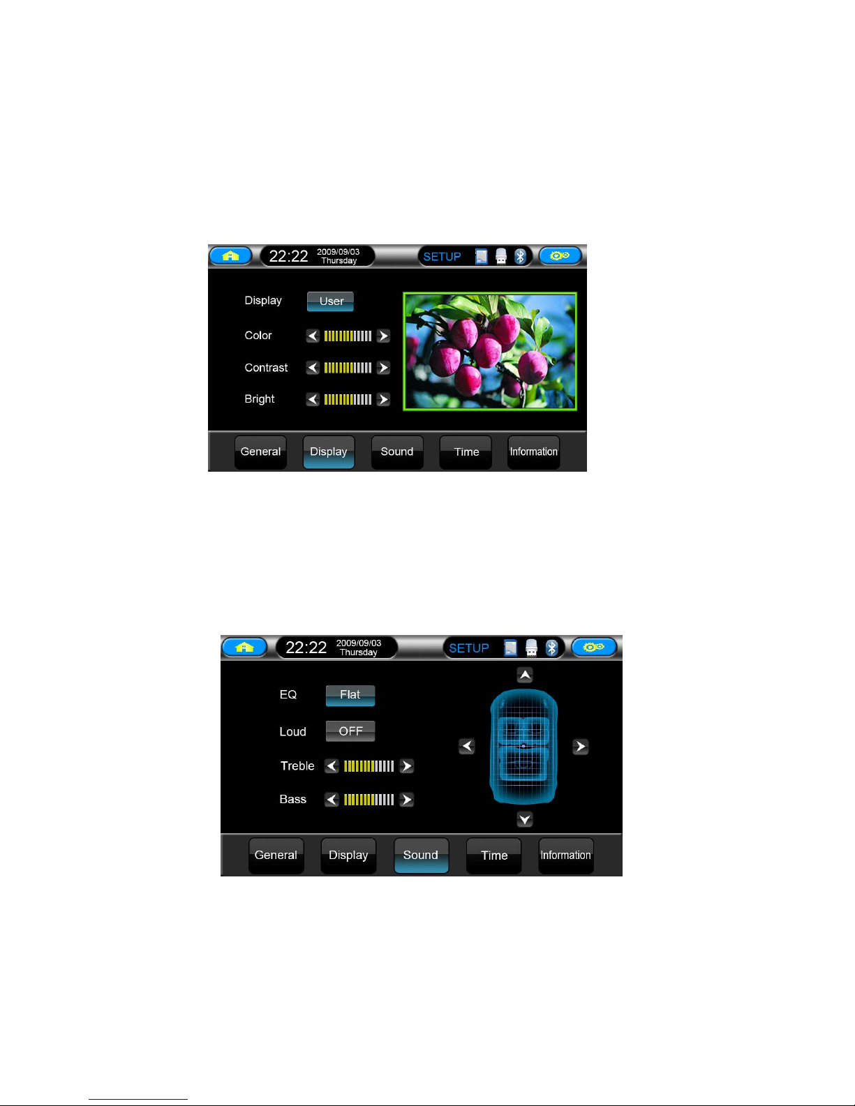
● Display setup
Press 2 display setup buttons to setup display mode, color, brightness,
contrast separately.
● Voice setup
Press 3 voice setup buttons to setup EQ mode, loudness, treble, bass and the
balance of four loudspeakers which are in front, back, left, right of car
separately.
● Time setup
Press 4 time setup button to setup time and date separately
● Return to main menu
Press 14 returns to main menu mode.
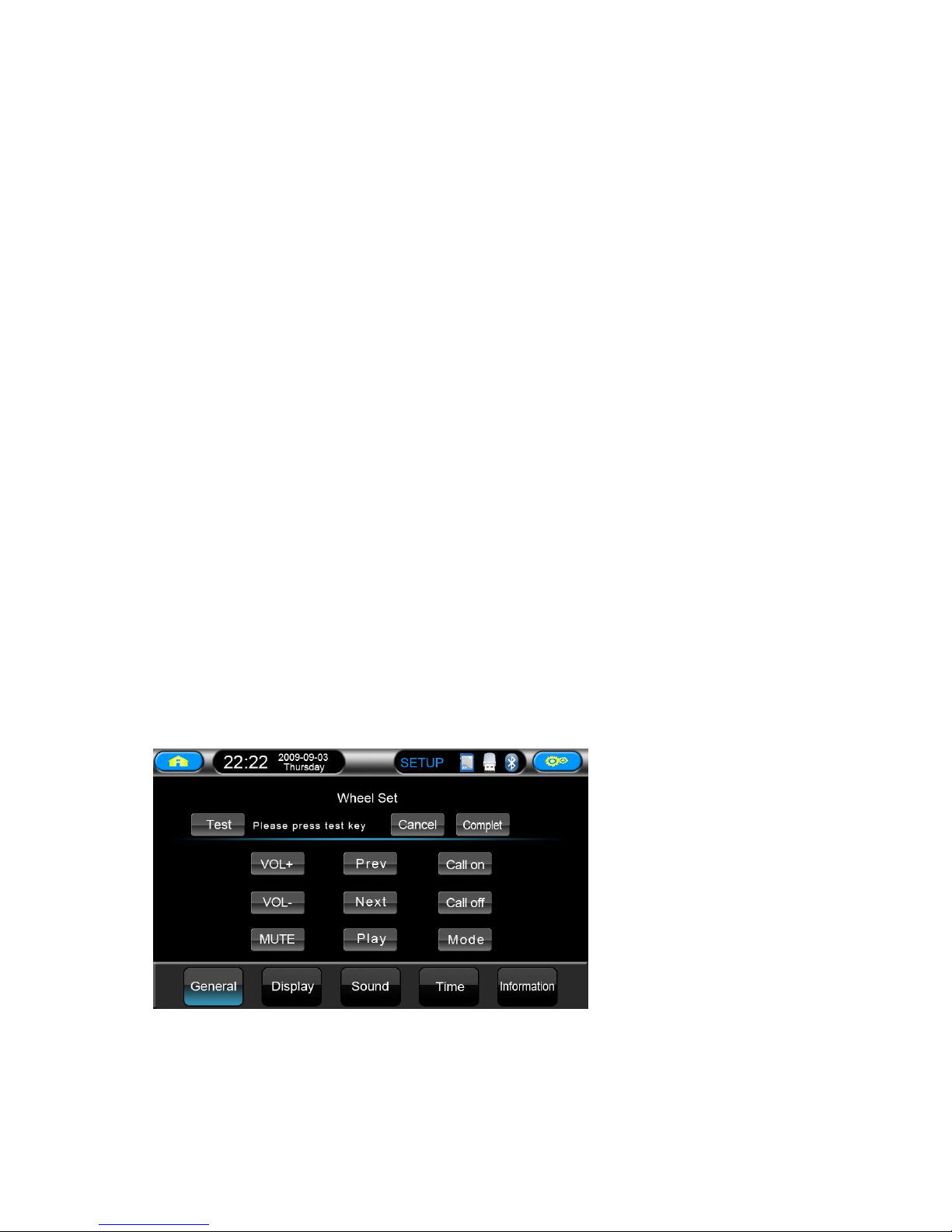
● Steering wheel setup
Setup and use of steering wheel:
If your car with steering wheel control, please operate as follows:
1. Under the circumstance of power cut off, find the grounding wire of your car's steering
Page 13

13
wheel wires, (Note: some cars have three pieces of wires, others have two pieces), then,
connect it to the grounding wire of three pieces of steering wheel wires drew forth from the
main unit. If your car's steering wheel has three pieces of wires, connect the other two pieces
of key wires to the rest two pieces of key wires drew forth from the main unit, you can
connect them at will; if your car's steering wheel has two pieces of wire totally, you can
connect the rest one to any piece of the rest two pieces of key wire drew forth from the main
unit;
2. Supply the power to turn on the unit after you confirm the steering wheel connection
wires all correct, press the setup button of upper right corner in the screen to enter setup
menu;
3. Press the center of direction setup button in the top of setup menu, the steering wheel
setup menu will bound out;
4. After steering wheel setup menu bound out, press text button firstly, you will see sample
figure of A and B displayed in information box, this is the initial figure that the main unit get
sample to car's steering wheel.
5. Then, press the following key "cancel" firstly to clear all keys. Note: you must press this
key to clear all previous setting before every to change setting.
6. And then, you can make the keys learn. after you press the top function key, the
information box will prompt "PLS PRESS KEY" to prompt user to press key of car's steering
wheel that need to define. when you have pressed the key of car's steering wheel, the
information box will display the key figure that you pressed, that means the key has been got
sample by main unit, then, you can learn the next key till finish all keys learning.
7. When complete the learning, you need to press "complete" to save the key you have
learned and start steering wheel function, if you didn't press "apply" key after finished
learning, before you will study will make invalid processing.
8. If you don't want it after finish learning, press "cancel" to cancel it, at the same time,
close the steering wheel function.
9. If you think that some keys' sample figures are very close during learning and it's easy to
mistake code, press exchange two wires, means exchange previous two pieces of wires from
car steering wheel to unit drew forth. If the car's steering wheel just has one piece of wire,
please connect the key wire of steering wheel to the other wire of unit, then return to the first
step to learn.
10. Maybe there are several keys in car's steering wheel, you can define by yourself, make
the key function of steering wheel and key function in menu correspondence, and finish
learning. You can ignore it if a key in menu but not in steering wheel, it won't influence
normal use. You just need to learn the keys which are in steering wheel's OK.
11. You can also enter setup menu and press "cancel" to close steering wheel function after
finish learning steering wheel. After closed the steering wheel will have no function. If you
need to turn on steering wheel function, please return to the first step and re-learn to setup.
Page 14
14
●Display setup
·Press the display mode right picture shows which has four kinds of mode to
select:
Customize→Standard→Bright→Soft
·Press the right picture shows “color” “contrast” “brightness” to adjust the color,
contrast and brightness of display screen at will separately.
● Voice setup
·Press “EQ mode” button of right picture shows which has five kinds of mode
to adjust:
Standard→Rock→Popular→Jazz→Classical
·Press “loudness” button of right picture shows to choose “turn on” or “ turn
Page 15

15
off” the loudness.
·Press the left or right button of “treble” and “bass” you can adjust treble or
bass by yourself.
·Press car’s up, down, left, right button as right picture which can come to the
adjustment to car’s front, back, left, right loudspeakers.
● Time setup
·Press time adjustment button and button to setup time and date.
·Press time adjustment button to setup the time display is “12H” or “24H”.
·Press date adjustment of right picture button and button to adjust
date’s year, month, day.
·After finish the adjustment, Please【Submission】button and then exit the time
setup menu.
● Edition information
·Press edition button, It will display the software’s edition information.
9. Radio mode
1. Automatically scan radio
2. Scan
3. Loc
4. Single track/stereo switch
5. TA (RDS) (optional)
6. AF (RDS) (optional)
7. PTY (RDS) (optional)
8.Mute
Page 16

16
9.Voulume
10.Manual scan radio+
11.Manual scan radio-
12.Wave band switch
13.Return to main menu
14.General setup
15.Status and time display
16. Favorite radios
Automatically scan radio
·Press 1【auto-scan radio】button, the unit will auto-scan radio, and save them
into 1-6 button of each wave band.
●Scan
·Press 2【browse】button, it auto-scan radio which is per-set in 1-6 button of
each wave band, Every radio is displayed for 10 minutes.
● Loc
·Press 3【Loc】button to setup remote or short-range scan radio mode of unit, if
be setup in the short-range scan radio mode, the unit just receive local strong
signal radio. If be setup in remote mode, it will receive local and remote radios.
● Stereo and single track switch:
·Press 4【ST】button to setup stereo and single track receive radio mode.
● RDS(optional function)
·If no RDS, or RDS is closed, 5-7 are Invalid.
A.【PTY】press 7 to choose your favorite programs style, 2 seconds later it will
auto-scan program of the program style you setup.
B.【TA】after you press5, it will to auto-search RDS display radio.
C.【AF】AF function is setup to be open while being again, Press 5 to close or
re-open it,
If the current signal is weak, within 50 seconds the unit will auto-search and
display strong signal radio of same style.
● Manual Scan
·Press 10【 】and 【 】 to choose different radio channels upward and
downward. Long press 10【 】and【 】the unit will search the channels
upward or downward automatically, It stops when a channel is searched.
● Band switch:
·Press 12【Band】to switch the radio band. The switching order is as follows:
FM1→FM2→FM3→AM1→AM2
● Favorite radio channels:
·When the unit receive a favorite channel, You can press one of the buttons in
1-6 keys for 2 seconds to save it in this button. Press 1-6key to play the preset
channel. Show as picture 16.
Page 17

17
● Return to main menu:
·Press 13 to return to the main menu
● General setup:
·Press 14 and the general setup menu shows up.
Snap: In DVD/USB/SD/IPOD/AUX video mode, press the picture and the setup
interface as above will be shown, you can then set the settings as demanded; it
will turn full screen display if there is no operation within 10 seconds, or if you
press the picture again.
10. DVD/SD/MMC/USB operations
The unit will enter the DVD mode automatically when you put in a disc, if there is a disc
inside the device, you can also enter the DVD mode by pressing DVD icon in the menu status,
Enter/eject disc button.
1. Eject
2. Play/ pause
3. Stop
4. Direction key
5. Menu display
6. Catalog function
7. Audio
8. Zoom
9. Volume+/-
11. Repeat play
12. Fast forward
13. Fast backward
14. Previous
15. Next
16. Return to main menu
17. General setup menu
18. Status/time
19. System
20. Random button
21. DVD setup button
22. Title button
23. Display button
24. Scan button
25. OK
26. Up
27. Down
28. Left
Page 18

18
29. Right
◆Enter/eject
Press button 1 control the enter or eject of the disc.
◆Play/pause
Press button 2 to pause, press it again to recover normal play.
◆Stop:
Press button 3 to stop playing, and press2 to play again.
◆Direction keys:
Press button 4 P1 to enter the second page, 4 will display P2, press P2 to
enter the
Third page, button 4 display P3, Press P3 to enter the first page.
◆Menu play:
Press buuton5 [menu] to enter the menu mode. [Note: the disc should be the
VCD2.0, which supports the menu play or DVD].
◆Catalog function:
Press 6 [catalog] to choose various catalog of DVD.
◆Track function operation
Press 7 [track] to switch the set of left track, right track, mixed track, stereo,
language (which should be supported by disc) freely.
◆ Reduce and enlarge:
Press 8 [reduce and enlarge] to reduce or enlarge the display picture by
times, you may refer to remote control introduction.
◆Volume control:
The volumes increase/decrease if you press 9 volume button.
◆Repeat play:
Press button 11 to set the repeat mode and the repeat sequence is as follow:
All repeat→single repeat→repeat off
Note: the default mode is "all repeat".
◆ Fast forward / fast backward:
Press 12 and 13 button to play fast forward and fast backward. Press 12
continuously to play fast forward [×2×4×8×20]. Press button directly in fast
forward or fast backward to return to the normal play.
◆Select program setup:
Press button 14 or 15 to choose next or previous.
◆Return to main menu:
Press button 16 to return to main menu.
◆General setup menu:
Press button 17 and the general setup menu shows up. For details, please refer
Page 19

19
to the general setup from page 9.
◆System button:
Press 19 [system] to choose NTSC or PAL system.
◆Random button:
Press 20 [random] to play programs in DVD randomly.
◆DVD setup:
Press 21 [setup] to setup DVD mode.
◆Title button:
Press 22 [title] to display the title catalog in DVD.
◆Display button:
Press 23 [display] to display play time and programs of DVD.
◆Scan:
Press 24 [scan] to scan Program in DVD.
◆Confirm:
Press 26-29, up, down, left, right to choose the status you want. Press 25 [OK]
to confirm.
Click TV icon in the main menu to enter the TV mode (can choose analog TV)
11. TV mode
Analog TV
1. TV system setup
2. Automatic scan
3. Previous channel
4. Next channel
5. Mute
6. Volume+/ -
7. General setup menu
8. Status and time
9. Return to main menu
◆TV system setup
Press 1 [TV setup] repeatedly to select the correct TV audio/video system. The
selection sequence is as follows:
PAL_L→PAL_DK→PAL-BG→SECAML→SECAM_BG→SECAM_DK→
NTSC_M
◆Preset the TV
Press 2 [automatic scan] to scan and save the TV automatically. It can save up
to 99 radio channels.
◆Volume control
Press button 6 to control the volume to increase and decrease. The volume is
Split into 30 grades. If you turn off the unit [or close the ACC lock] when the
volume is set below 10, the unit will come to the previous volume when you
restart the device; if the volume is set above 10, the unit will restore to default 10
after you restart the unit.
Page 20

20
◆Channel selection:
Press 4 and 3 buttons to select the previous channel and next channel
respectively.
Digital TV
1. Menu
2. Track
3. Previous channel
4. Next channel
5. Volume +/-
6. General setup
7. Status and time
8. Return to main menu
9. Catalog
10. Exit button
11. Scan radio button
◆Menu
Press 1 [menu] to display digital TV.
◆Track
Press 2 [track] to control digital TV left track and right track.
◆Volume control
Press button 5 to control the volume to increase and decrease. The volume is
Split into 20 grades. If you turn off the unit [or close the ACC lock] when the
volume is set below 10, the unit will come to the previous volume when you
restart the device; if the volume is set above
10, the unit will restore to default 10 after you restart the unit.
◆Channel selection
Press 3 and 4 to select previous channel and next channel respectively.
◆Catalog
Press 9 [catalog] to control digital TV catalog.
◆Exit
Press 10 [exit] to exit digital TV interface.
◆Scan radio
Press 11 [scan] to scan digital TV channels.
12. GPS Navigation Operation
◆Select GPS in main interface
Page 21

21
◆Enter the GPS interface as below:
1. Navigation
2. GPS Setup
3. Entertainment
Press 1[Navigation] in the GPS main menu to enter the GPS console; press [2]
to set up the map, Details as below GPS setup
Press【3】Entertainment to enter E-book, Music, and Movie to go to
corresponding mode. ( must exist corresponding content in SD card).
GPS setup:
Press icon 2 in the GPS main menu to
enter the setup menu; Will show the
follow picture:
Press Navigation setup, usual setup, GPS
monitor, Touch screen, Screen, language,
Time, , and System to enter the
corresponding interface.
Navigation Setup:
Page 22

22
Press "Navigation setup" to enter the map path setup interface, press [1] and
choose the path of the map, then, find the GPS map file (exe) and save it. Press [2]
to return to the GPS menu; then, press navigation icon to start the GPS operation.
◆Usual setup:
Press "Usual setup" to enter the setup interface. You can set the volume, key
sound, and language here.
◆GPS monitor:
Press "GPS monitor" to enter the GPS monitor interface. You can see the
information about the GPS satellite status.
◆Touch screen:
Press "Touch screen" to enter the calibration interface. Use the special pen to
click the five calibration points for 2 seconds in turn. The screen displays OK
when the calibration is
Successful, then, press OK to return to the setup menu.
◆Screen setup:
Press "Screen" to enter the screen setup interface. You can set the brightness,
color/size/position here.
Note: it is recommended to set the screen size to be default. Level: 0; Vertical:
6.
◆Time setup:
Press "Time" to enter the clock setup interface. You can set the clock and
time zone here.
◆Skin setup:
Press "Skin" to enter the skin setup interface to choose the different skins and
picture switching effects.
◆System setup:
Press "System" to enter the system setup interface.
Note: the navigation interface and function may vary from the map
software. For details navigation operations, please refer to the interface of
the map.
13. Bluetooth
Please note the several following points before reading the Bluetooth operating
instructions:
◆To connect the mobile phone Bluetooth, enter “Bluetooth” panel and press
button to match.
◆After the successful match, the Bluetooth picture will turn to “Bluetooth
icon”.
◆Default matching password is 0000.
Page 23

23
Phone dial number
1. Dial / receive calls
2. Refuse / hang off calls
3. Backspacing
4. Bluetooth / mobile phone
switching key
5. Phone book
6. Music display
7. Bluetooth setup
8. Number key
9. Number display
10. Return to main menu
11. Status and time display
12. General setup
Phone Book
1. Phone book
2. Dialed calls
3. Received calls
4. Missed calls
5. Bluetooth / mobile phone
switching
6. Next
7. Previous
Bluetooth Music
◆The Bluetooth of this DVD
supports A2DP, stereo Bluetooth
music play protocol and automatic
control. If the matched mobile
phone supports the functions, you
just need to press 1 in the standby
mode under the A2DP
communication protocol, then, the
device will control the mobile
phone automatically to play its
music. You can press 1 to pause
when play the music. The device
returns to normal when you press it again. Press 2 to stop playing and 1 to start to
play again. Press 3 to select the next program and 4 to select the previous
program.
Page 24

24
Bluetooth setup
◆Press 1 [reset] to see the save data of
Bluetooth.Press2 [cut] to cut the
connecting Bluetooth. Press3 [connection]
to connect Bluetooth.
◆Press 4 to increase/decrease the volume
of Bluetooth,
14. IPod operating mode
1. Volume + /-
2. Random Button
3. Turn off
4. Repeat
5. Confirm
6. Video
7. Previous video
8. Next video
9. Next
10. Play/pause
11. Previous
12. Menu
13. Return to main menu
14. General setup menu
15. Status and time
Volume control ◆
Press 1 button to control the volume to increase and decrease. The volume is
Split into 30 grades. If you turn off the unit [or close the ACC lock] when the
volume is set below 10, the unit will come to the previous volume when you
restart the device; if the volume is set above 10, the unit will restore to default
10 after you restart the unit.
Random ◆
Press 2[random] to play audio and video in IPOD randomly.
Turn off ◆
Press 3 [turn off] to close IPOD connecting status, IPOD will charge power
immediately.
Repeat ◆
Press 4 [repeat] to replay current program or cyclical replay all programs.
Page 25

25
M◆ enu play
Press 12 [menu] to enter menu play mode.
Program selection setup: ◆
Press 9 or 11 to select next or previous respectively.
In play status: ◆
Press 10 to pause / play, press it again to recover normal play.
In play status: ◆
Press 6 [video] to enter video play; press 7 to select previous video, press 8 to
select next video.
15. AUX mode
1. Volume -
2. Volume +
3. Mute / vocal
◆Press 2 [+] and 1 [-] button to control
the volume to increase and decrease. The volume is Split into 30 grades. If you
turn off the unit [or close the ACC lock] when the volume is set below 10, the
unit will come to the previous volume when you restart the device; if the
volume is set above 10, the unit will restore to default 10 after you restart the
unit.
Speaker◆ status display:
Press 3 means mute, press it again to return to the vocal status.
16. System Setup Menu
You can press Setup key on the remote control to bring up the System Setup Menu when the
unit is under the stop/playback mode.
SETUP MENU Main Page
Press up/down direction button to select a item, then press
ENTER.
System Setup
Page 26

26
TV SYSTEM
According to the Color System of the TV, you can choose the TV System.
AUTO: Choose this settings if your DVD player is connected to a multi-system TV.
NTSC: Choose this settings if your DVD player is connected to a NTSC TV.
PAL: Choose this settings if your DVD player is connected to a PAL TV.
PAL60: Choose this settings if your DVD player is connected to a PAL60 TV.
The default setting is NTSC.
SCREEN SAVER
If the screen saver is on, when your DVD player is in Stop, Open, or No Disc state, or there is
a frame frozen for more than 3 minutes, the screen saver will be displayed. This feature can
protect the screen from damage.
ON: Choose this setting to activate the screen saver.
OFF: Choose this setting to cancel the screen saver
The default setting is ON.
TV TYPE
16: 9 (Wide Screen): Choose this setting if your DVD player is connected to a wide screen
TV. If you choose this setting and you don’t have a wide screen TV, the images on the screen
may appear distorted due to vertical compression.
4: 3 LB (Letter Box): Choosing this setting if your DVD player is connected to a normal
ratio TV. connector You’ll see the movies in their original aspect ratio (height-to-width ratio).
You’ll see the entire frame of the movie, but it will take up a smaller portion of the screen
vertically. The movie might appear with black bars at the top and bottom of the screen.
4 : 3 PS (Pan & Scan): Choosing this setting if your DVD player is connected to a normal
ratio TV. You can fill the movie to the entire screen of your TV. This might mean that parts of
the picture (the left and right edges) won’t be seen.
PASSWORD
The password option is initialized locked, and you cannot set the ratings limit or change the
password. In order for the Ratings feature work, the password mode must be turned on. If you
want to set the ratings limit, you will need to enter the default password, which is 0000, then
press Enter to confirm. To change the password, you will be prompted for the old password,
then be prompted for a new. Enter a 4-digit number (this is your password).
Notes: Some time, the password is 6-digit number, the default is 000000.
RATING
The Rating feature is a rating limit system, like movie ratings. It works with DVD discs that
Page 27

27
have been assigned a rating. This helps you control the types of DVDs that your family
watches.
There are two rating options: NO ADULT and KID SAFE.
Select the VIEW ALL option to cancel the rating limit.
The default setting is VIEW ALL.
DEFAULT
Choose this option to resume all the setup options to default settings.
LANGUAGE SETUP
OSD LANGUAGE
press the Arrow buttons to choose the OSD language you prefer. Press Enter to confirm, and
it will display OSD in that language; There are 8 optional OSD languages: Chinese, English,
Japan, French, Spanish, Portuguese, German and Latin.
AUDIO LANGUAGE
press the Arrow buttons to choose the audio language you prefer. Press Enter to confirm. If
the disc you are playing has that language available, it will output audio in that language;
There are 8 optional audio languages: Chinese, English, Japan, French, Spanish, Portuguese,
German and Latin.
SUBTITLE LANGUAGE
press the Arrow buttons to choose the subtitle language you prefer. Press Enter to confirm. If
the disc you are playing has that language available, it will displays subtitles in that language;
There are 8 optional audio languages: Chinese, English, Japan, French, Spanish, Portuguese,
German, and Off.
MENU LANGUAGE
press the Arrow buttons to choose the menu language you prefer. Press Enter to confirm. If
the disc you are playing has that language available, it will displays menu in that language;
Page 28

28
There are 8 optional menu languages: Chinese, English, Japan, French, Spanish, Portuguese,
German, and Off.
AUDIO Setup
KEY
Use the Up and Down arrow button to
move the scroll and adjust the key.
VIDEO SETUP
BRIGHTNESS
Use the Up and Down arrow button to
move the scroll and adjust the brightness.
CONTRAST
Use the Up and Down arrow button to
move the scroll and adjust the contrast.
HUE
Use the Up and Down arrow button to
move the scroll and adjust the hue.
SATURATION
Use the Up and Down arrow button to
move the scroll and adjust the saturation.
DIGITAL SETUP
DYNAMIC RANGE:
When “LINE OUT” is selected, choose
this setting to adjust the line out ratio and
get different effect. If adjusting to FULL,
the audio signal peak value will be the
minimum; while adjusting to OFF,
maximum. DUAL MONO
Choose this option to setup the L and R
mono output mode; There are four modes
in this option: STEREO, MONO L,
MONO R, and MIX MONO; It is mainly
used in karaoke mode.
Page 29

29
17. Remote Control
1. Power supply
2. Play/Pause
3. Enter/Eject
4. Direction keys
5. Band/System switching button
6. Enter
7. Volume +/-
8. Select the channel/program/Fast
backward/forward
9. Programming/Stereo
10. Playing time display
11. GPS screen switching
12. Repeat/Automatically save the channel
13. Random play/Local & remote control
14. Number keys
15. Audio settings
16. PBC settings
17. Mute
18. Desired program
19. Mode switching
20. Stop/Return
21. Angle selection
22. Title/Language settings
23. Main menu setup
24. Title/Catalog settings
25. Zoom in/Zoom out
26. GPS shortcut/mode
27. TFT screen up-sliding key
28. TFT screen down-sliding key
29. Compensation of equal-loudness
Page 30

30
18. Troubleshooting
Note: Please ask the local distributor for help if the above settlement do not
Problems Reasons and settlement
No power Check whether the fuse of power supply is broken.
Change for another one with a proper capacity if necessary.
LCD display mess-up and
the key does not work
Press Reset Key
Cannot receive the radio
channel
Check whether the antenna is connected or whether it is
connected well. Connect the antenna well.
Bad effect on receiving
the radio
The length of the antenna may not enough. Check whether the
antenna is spread out or broken. Change for a new one if it is
broken.
The broadcasting signal is too weak, change for another one with
a strong signal.
The antenna is not connected to the ground properly. Make sure
whether the antenna is connected well to the ground.
Cannot put the disc into
the DVD
There is a disc inside the DVD. Withdraw the disc to solve it.
Stereo indicator flashes Perfect the tuning frequency
The broadcasting signal is too weak. Please set it in the MONO
mode
Noise The disc is broken or dirty. Change for a good disc.
No picture The video cable between the DVD and TV is not connected well.
The picture shake The system color setting is not correct. Set the color system to
"PAT" or "NTSC" according to your TV.
Bluetooth cannot work Check whether the Bluetooth mobile phone matches the DVD and
whether it is correctly connected to the DVD. Match and connect
it again according to the instruction of the mobile phone.
Echo is too loud in
Bluetooth talk
The volume is too loud. Turn the DVD down to a proper volume.
The Bluetooth mobile
phone music and talk is
played off and on
Check whether the Bluetooth mobile phone is placed too far away
from the DVD.
Put the mobile phone to a proper position within 5 meters from
the DVD.
Page 31

31
work. Do not Repair by yourself.
19. Specifications:
General
Power supply
Load
Max. Power output
Tone control
Dimensions
Installation dimension
Weight
DVD chip
Applicable disc
Video system
Installation angle
Video
Video system
Video output
Horizontal resolution
Audio
Max. Output
Frequency scope
S/N ratio
Resolution
AM tuning
Frequency scope
MF frequency
Practical sensitivity (-20db)
FM tuning
Frequency scope
MF frequency
Effective sensitivity (-30db)
S/N ratio
Stereo Channels Crosstalk
14.4VDC
4 Ω
50W*4
+/-8db (Bass: 100Hz, Treble: 10 KHz)
About 192*178*100mm (D*W*H)
About 169*182*103mm (D*W*H)
About 2.65 Kg
MPEG4.DVD,SUPER VCD, MP3, CD,
CD-R, CD-RW, PICTURE-CD
AUTO, NTSC, PAL
0-+/-30·
16:9 Mail MODE/16:9FULL SCREEN
1.0Vp-p.75ohms
500
600 Ω (2.0Vrms)
20Hz-20 KHz
85db
80db
522-1620(Europe/China/Russia), 530-1710
450 KHz
25db
87.5-108 (Europe/China), 65-74; 87.5-108
87.5-107.9 (USA)
10.7MHz
15db
60db
30db (1 KHz)
NOTE: Refer the upgrade of the unit, Technical features updating, No
Page 32

32
more advice from fty!
 Loading...