

Page 1

XT-NET
User’s guide
1/15
Page 2
XT-NET
XT-NET
User’s guide
CONTENTS
1. System requirements
2. Installing the Software
3. Connecting to the processor
3.1 Connection via RS232
3.2 Connection via Network Interface
4. Managing the processor
4.1 Layout
4.2 Menu
4.3 Toolbar
5. Going Online
6. Launching a Panel
7. Parameter Synchronisation
8. Progress Bar
9. Navigation
10. Selecting a Device
11. Device Context Menu
1. SYSTEM REQUIREMENTS
The minimum hardware requirements necessary for acceptable performance are a Pentium processor 450MHz and 128MB of RAM.
Network Controller has been created for Microsoft Windows© 32-
bit (NT, 98*, ME*, 2000, XP, Vista) operating systems.
*Note: In theory it should be possible to run Network Controller using Windows 98 or
Millennium Edition operating systems; however we do not recommend using these versions as they have limited resources. If you do use these versions remember to close all
the other applications before running Network Controller.
Network Controller has been developed using the most modern
technology in software development, in particular it has been developed using the .NET Framework. Therefore, before installation,
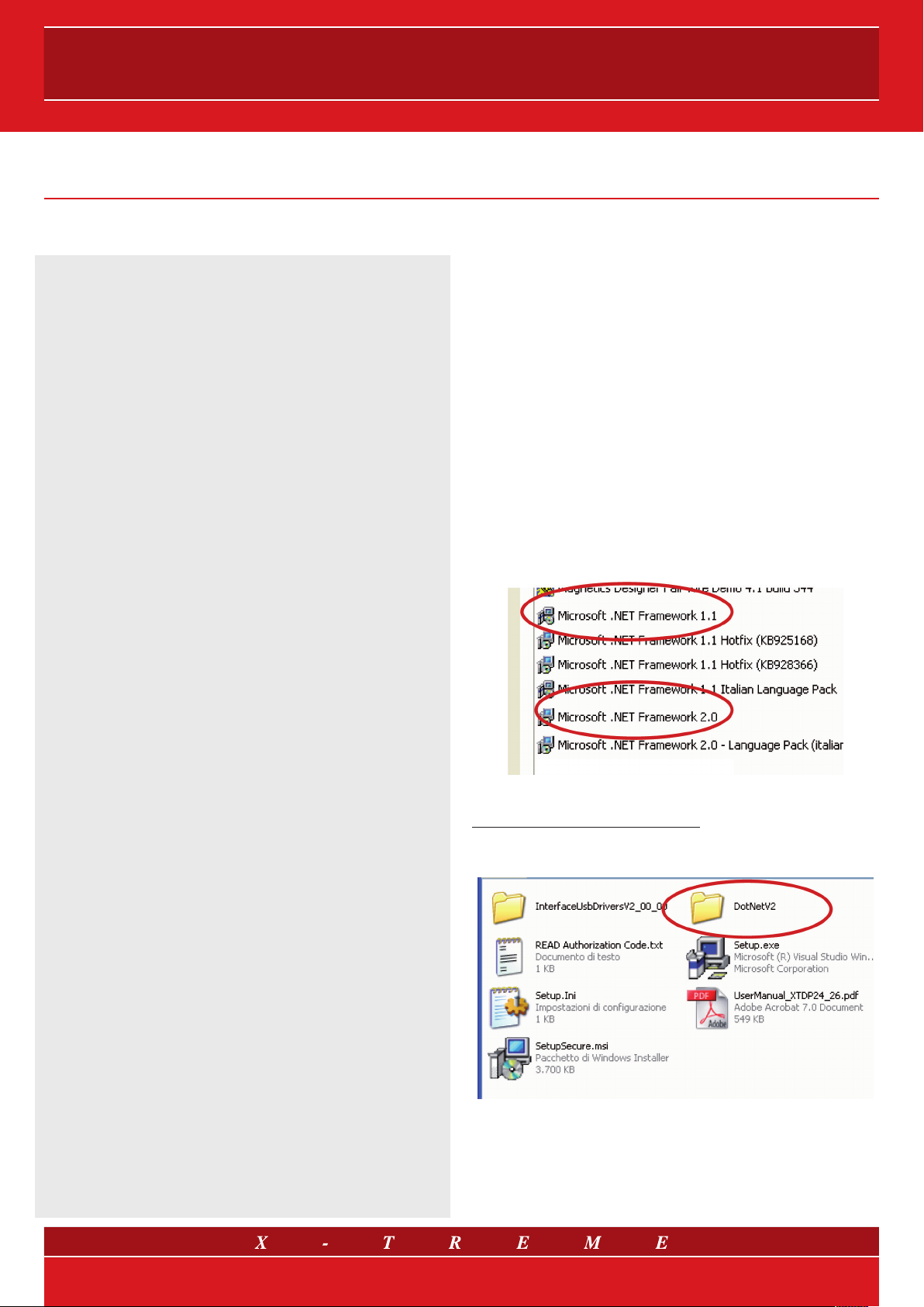
.NET Framework is required. To verify whether .NET Framework is
installed on your PC, from Start go to the Control Panel, open Application Installation and verify that Microsoft .NET Framework 1.1
or Microsoft .NET Framework 2.0 is included in the list of programs
already installed.
12. Control Panels
13. Monicons
14. Controls
14.1 Drop-Down Selector boxes
14.2 Spin boxes
14.3 Buttons
14.4 Radio buttons
14.5 Faders
14.6 Filter Response Panels
14.7 Copy Graphics
14.8 Copy/Paste Settings
15. Offline Operation
16. Saving Data
17. Loading Factory Settings
18. Cloning a Device
19. Presets
20. Device Properties
21. Device Firmware
If .NET Framework is not on the list of programs installed, it can be
downloaded for free from:
http://www.microsoft.com/downloads
A copy of the .NET Framework installation file can be found in the
DotNetV2 folder on the attached CD.
22. Keyboard Shortcuts
2/15
Page 3
User’s guide
2. INSTALLING THE SOFTWARE
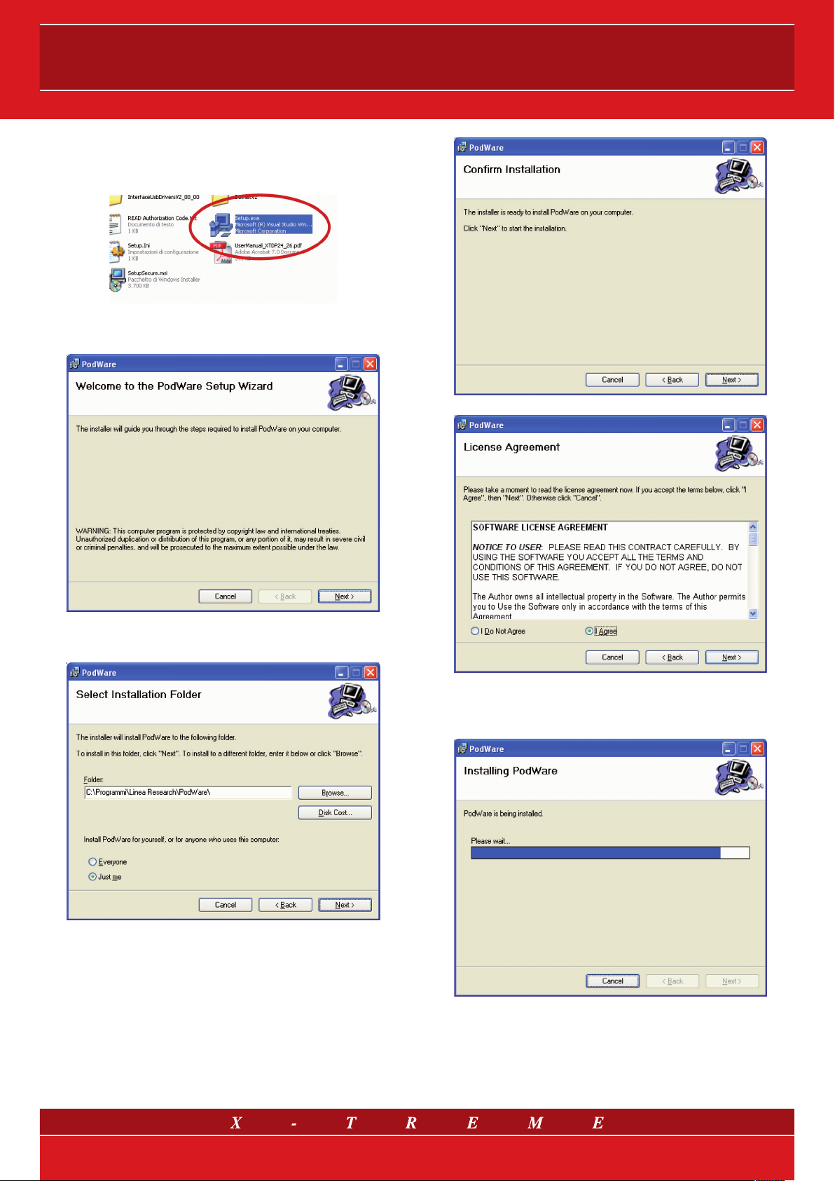
To install Network Controller, from the CD, double click on the file
Setup.exe.
The following window will appear:
Click on Next> to start installation.
Choose whether you want to install the software for all the users of
the PC or only for the current user and click on Next> to continue.
Select I Agree to accept the software licence conditions, click on
Next> to continue with installation. Wait a few moments:
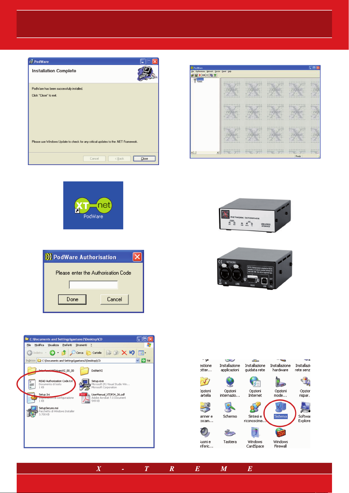
Click on Close to end installation.
3/15
Page 4
XT-NET
A window like this will appear:
Once installation is completed the following icon can be found on
the pc desktop:
Double click to run Network Controller. When running for the first
time the authorisation code will be requested:
The code can be found in the “READ Authorisation Code.txt” file on
the attached CD. Enter the code and click on Done to confirm.
3. CONNECTING TO THE PROCESSOR
Connection to the processor can be done in two ways.
1) By using the serial port (RS232);
2) By using XT-NETINT external device (shown below).
3.1 Connection via RS232
If you choose to connect to the processor via the RS232 connector, you must ensure that the Personal Computer has a serial port,
otherwise (as with the majority of portable PCs) you will have to use
a USB to Serial adapter. In this case, we should point out that before
making the connection you must ensure that the adaptor is correctly
installed and that the serial port (a “virtual COM”) is visible to the
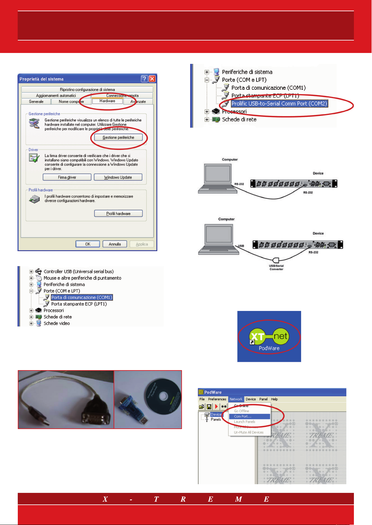
operating system. In order to verify this, from the Control Panel open
the System Management.
4/15
Page 5
User’s guide
Select the Hardware device and select Peripheral management:
In this case the system recognises the USB to Serial adapter as
COM2. This port must be used to connect to the processor.
Fig. 2 Connection via serial port
Verify that there is a COMx communication port and that it functions correctly (COM1 in this example). If there is no COMx physically
present, install a “USB to Serial” adaptor and verify the number of the
serial port with which the adapter is recognised by the system.
Fig. 1 Two different model USB to RS232 adapter
Proceed as above to arrive at the list of hardware on the PC, if installation has been carried out correctly you should be able to see the
new hardware.
Fig. 3 Connection via USB/Serial adapter
Run the Network Controller software by double clicking on the
XT-NET PodWare icon.
5/15
Page 6

XT-NET
Verify the COM port to be used, then from the Network menu select
Com Port.
Choose the COM port that you wish to use to connect to the processor (that is the COMx port available in the PC if connection is made
without USB/Serial adapters or the virtual COM port installed by the
operating system if you use USB to Serial adapters). Once the COM
port has been correctly chosen, in order to establish a connection with
the processor, simply click on the Go On Line button on the tool bar.
2) if you wish to use the Network Interface via USB port, simply connect the device to the personal computer and the new software will
be automatically recognised by the operating system and will need
an installation driver.
Fig. 5 Connection via USB port
Follow the operating system configuration procedure for the installation
of the new hardware and indicate the “InterfaceUsbDriversV2_00_00”
folder as the origin of the installation files on the attached CD.
At this point the devices available in the network will be tested and will
appear in the list of Devices.
3.2 Connection via Network Interface
Installation and verification of the Network Interface
If you use the XT-NETINT Network Interface that allows for remote
handling from a distance of up to 1 km and the control of more than
100 network devices, first of all you must install the driver for the peripheral. Proceed in the following way:
1) if you wish to use the Network Interface via serial port you do not
have to install any driver. You must remember that if used in this way
the Network Interface needs a 12V external power supply:
Once installation is completed check which COM port has been assigned by the operating system to the new hardware. Go to the list
of peripherals by following the usual path (Start> Control Panel> Sys-
tem > Hardware> Peripheral Management) and verify the presence
of the following adapter.
In this case use COM6 for connecting to the processor. Run
the Network Controller software by double clicking on the
XT-NET PodWare icon.
Fig. 4 Connection via RS-232 serial port
6/15
Page 7

User’s guide
Check which COM port is to be used, then from the Network menu
select Com Port.
4. MANAGING THE PROCESSOR
Network Controller can automatically discover devices connected to
the networks you tell it you would like to use. The connected devices
are then presented to you in an organised Tree, ready for you to select
the panels you would like to display and manipulate.
Select the COM port that you have decided to use to connect to the
processor. Click on the Go Online button on the toolbar.
At this point the devices available in the network will be tested and will
appear in the list of Devices.
When devices are arranged in the main window, their default representation is a Monicon - an icon which conveys basic monitoring
status indication. This Icon can usually then be opened up to the full
control panel by clicking on a navigation button.
Fig. 5 Example of a MonIcon
Any number of Monicons and full panels may be displayed and organised on the screen automatically or manually. Each device type
usually has a predefined Monicon and control panel associated with
it, the latter containing controls for all the parameters you can adjust
within the device. Adjusting any of the controls on the panel whilst on-
line will cause adjustments to be made in the relevant device in “real
time”. A comprehensive set of features allow you to save and retrieve
stored parameter sets, manipulate presets, etc.
7/15
Page 8

XT-NET
4.1 Layout
When Network Controller is launched, its main window comprises
three main areas:
1. A Tree panel on the left for navigating among devices and panel;
2. A toolbar at the top with the most commonly used actions available
at a single mouse click;
3. A control panel area (the remainder of the window) for device Monicons and control panels.
The user may adjust the size of the application window by dragging
the angle at the bottom-right of the main application window. The
Tree panel may be sized by dragging the split-line between the tree
and the main control panel area.
4.2 Menu
The menu system is arranged as follows:
Files
Open - opens a file which contains parameters for the selected device
Save - saves the current settings for the selected device in the cur-
rent file name
Save As - saves the current settings for the selected device under a
new file name
Load Factory Settings - updates factory settings in the selected
device (see Loading Factory Settings)
Open Device Clone - opens a file to clone the selected device
Save Device Clone - saves the settings of the selected device into
a cloning file (see Cloning a Device)
Exit - closes the application.
Preferences
Show Bandwidth As - allows you to set the units used in Bandwidth
controls
Show Delay As - allows you to set the units used in Delay controls
(see Controls).
Network
Go Online - allows communication with devices on the network
Go Offline - stops communication with devices on the network
Com Port - allows you to select which serial COM port you wish to
use
Launch Panels - launches the control panels for all the devices in
the network.
Panel
Tile Horizontally - arranges all the panels from left to right
Tile Vertically - arranges all the panels from top to bottom
Cascade - arranges all the panels in a heap from top-left to bottom-
right.
Help
Help topics . opens the help file (in your HTML viewer)
Some of these menu items have shortcuts using toolbar buttons (see
Toolbar).
4.3 Toolbar
The toolbar provides the following oneclick functions:
Open
Opens a file which contains parameters for the selected device. A
dialogue will appear, inviting you to choose a file to open.
Save
Saves the current settings for the selected device. If you have previously opened or saved a file, the settings will be saved in the same
file name, otherwise, a dialogue will appear inviting you to enter a
file name. If the settings have not changed since you last saved or
opened a file, the icon will appear greyed out, indicating that a save
is not necessary.
Online
Goes online/offline to/from the network. If a device cannot be found,
an error will be reported. While Network Controller remains online, this
toolbar button is coloured green; it is red when offline.
Locate
Flashes the indicators on the selected device (if online), to assist device identification, and as a quick check that communications are
working. This only works when online.
Mute All
Mutes (or Un-Mutes) every device in the system. When the speaker
in the button is red, the system is muted. A green speaker means
un-muted. This has nothing to do with channel mutes, which operate
completely independently. This state is not saved in devices; a power
cycle will cause a device to default to unmuted.
Launch All Panels
Launches the control panels for all of the devices on the network. This
only works when online.
Help
Launches Help topics. If you place the mouse cursor over a toolbar,
text fill appears describing the action of the button. If this text does
not show, click on the panel background (see The Selected Device).
Device
Locate - to locate the selected device (e.g. led flashing)
Update Firmware - update firmware in the selected device (See De-
vice Firmware)
Add Device Panel - allows a panel for a device to be added to the
layout while offline
Properties - lists device details which may be of interest for maintenance (see The Selected Device).
8/15
Page 9

User’s guide
5. GOING ONLINE
Network Controller queries the network, searching for compatible
devices. As Network Controller finds each device, it will add it to the
Devices node of the Tree, along with text describing the model of the
device, and the name of the device given by the user. Once all devices has have been discovered, you are ready to start controlling the
system by doubleclicking a device icon in the Tree to launch a control
panel (see Launching a Panel).
If Network Controller becomes unable to communicate with a device
for some reason whilst online (such as a break in the network cable),
the corresponding icon for it in the Devices node of the Tree will appear in red, indicating that control and monitoring on that device is
invalid. Most devices will allow themselves to be ‘rediscovered’ automatically if such a cable break is repaired.
6. LAUNCHING A PANEL
Once the application is online, and there are one or more devices in
the Devices node of the tree, a panel may be launched for a given
device in one of the following ways:
• By double-clicking on the appropriate Devices node of the Tree;
• By dragging a Devices node to the layout area of the main window;
• By dragging a Devices node to the Panels node of the Tree;
• By right-clicking on the Devices node and selecting Launch Panel
from the context menu (see Device Context Menu);
• By selecting Launch All Panels, either from the Toolbar (see Toolbar), or from the Network menu (see Menu).
After a few seconds, the panel (or more usually, the reduced-size Monicon) will appear in the layout part of the main window. At the same
time, an icon for the device will appear in the Panels node of the Tree.
This is now a fully functional real-time control panel for the connected
device. A Monicon may be enlarged to a full-size control panel by using navigation buttons (see Navigation).
Several control panels may be launched onto the layout, so that the
user can monitor the operation of several devices simultaneously. As
each panel is added, another icon is added to the layout node of the
Tree, indicating the presence of another panel in the layout. The panel
menu has features for arranging the panels into regular neat patterns
if required (see Menu).
Once the panel appears, the application will take a few seconds while
it copies the settings in the device to the control panel, as indicated
by the progress bar at the bottom-right of the main window.
To locate a panel for a particular device, just double-click on its icon in
the Panels node of the Tree. This will bring the associated panel to the
front, and highlight it (bring it into focus - see Navigation).
A panel may be removed from the layout by clicking on the ‘X’ in the
top-right corner of the panel. This action will also remove the device
icon from the Panels node of the Tree. The panel may be launched back
onto the layout by doubleclicking on the Devices icon in the Tree.
9/15
Page 10

XT-NET
7. PARAMETER SYNCHRONISATION
Network Controller aims to always ensure that the control settings
in the virtual control panel are always a faithful representation of the
settings in the connected device. To achieve this, the parameters in
the device are copied to the control panel when going online. This
takes a few seconds to complete (see Communications and Progress
Bar). Whilst online, any changes to the control settings will result in
changes in the stored parameters in the devices, thus retaining synchronisation. When a file is opened online, the new settings are not
only set in the control panel; they are also transferred to the device.
Clicking the ‘-’ on one of the main Tree nodes will close that branch,
allowing you to remove some detail from the Tree. Clicking the ‘+’
will restore the full detail. Panels will often have navigation buttons for
changing the amount of detail seen (and size of the panel).
A Monicon panel will have a ‘>’ button for expanding it into a full control panel. Similarly, a full panel will often have a ‘<’ button for reducing
the amount of detail (and panel size).
8. PROGRESS BAR
The area in the status bar at the bottom-right of the application window will indicate progress of some operations. A coloured bar will
extend to fill the extreme right-hand box, indicating progress from 0 to
100%, after which it will disappear. While in progress, the text to the
left of the bar will indicate what operation is being performed.
Loading will often be shown to indicate that the data is being transferred between the device and Network Controller.
While the progress bar is showing activity, it is best not to perform any
other actions in Network Controller.
9. NAVIGATION
The Tree view on the left-hand side of the screen allows you to view
the system. The two main nodes in the Tree are Devices, listing all the
compatible devices found on the network, and Panels, listing all the
control panels that have been launched onto the Layout.
Control panels may be launched by double-clicking on, or dragging a
Devices node (see Launching a Panel).
10. SELECTING A DEVICE
The “Selected Device” is the device to which operations from the
Device menu will be applied, and to whom related the toolbar button
actions (such as Locate, Save, Open) will be applied.
If a device is selected in the Tree view (by clicking on a device node or
a panel node so that the text of the node highlights), then this is the
selected device. If no device is selected in the Tree, then the control
panel in focus (the one whose colour is different to the others) will be
the selected device. If there are no panels in the layout, and no device
is selected in the Tree view, then no device is selected, and device
related operations will not work.
10/15
Page 11

User’s guide
11. DEVICE CONTEXT MENU
By right-clicking on the node of a device in the Tree, a ‘context menu’
will appear, providing you with the following possible actions:
Launch Panel - launches the control panel for this device
Rename Device - allows the Device Name to be changed
Update Firmware - update firmware in this device
(see Device Firmware)
Locate Device - to locate this device (e.g. led flashing)
Properties - lists device details which may be of interest for
maintenance.
If you do not wish to select any actions from the context menu, it
can be dismissed by pressing the ESC key, or by clicking the mouse
anywhere else in the application window.
12. CONTROL PANELS
Each panel will have a complete set of controls relating to the adjustable parameters within the device. Each control will contain the
current parameter value (see Parameter synchronisation). In some
panels, Tabs are used to distinguish between different sections of
the device. Single parameters may be adjusted “live” whilst online.
Also see Controls. Panels will often have a tool bar, with buttons for
executing commonly used functions such as File Open, File Save,
Locate and Help (see Tool Bar).
13. MONICONS
Monicons are a condensed representation of a device, which show
some monitoring status information, but few or no controls. Since
these are quite small, they are a convenient way of arranging the devices on the main window in a manner meaningful to the application.
Clicking the ‘>’ button will cause the full control panel for the device
to be displayed.
Some controls may allow the units of measurement used for displaying and adjusting values to be changed, such as Equaliser Band-
widths (which may be shown in Octaves or Q) or Delays, which may
be shown in distance or delay units. The units of measurement are
selected in the Preferences menu (see Menu).
14.1 Drop-Down Selector boxes
These are for selecting one item from a number of possibilities in a list.
Click the arrow on the right-hand end of the control to cause it to display a list of the options. Click on the text for that option to select it. If
there are many options to choose from, a scroll-bar will be shown, allowing you to scroll up and down the list by clicking the scroll arrows.
Note that once the control is highlighted, the PGUP, PGDN and Arrow
keys or the mouse wheel may also be used to change the selection.
14.2 Spin boxes
The value would normally be adjusted by clicking on the top button to
increase the displayed value, or on the bottom button to reduce the
displayed value. Holding the mouse button whilst on a button will after
a short delay cause the repeat mechanism to repeatedly increment or
decrement the value. Alternatively, values may be typed into the value
box directly. To do this, click in the value box and type in the new value.
The value you type in may include a minus sign, a decimal point, and/
or an engineering multiplier, such as ‘k’ to signify a multiplication of
1000. This may appear at the end of the typed string, or may be used
instead of a decimal point (such as 6k2 to mean 6200). Some controls
may auto-range as the value changes. For example, delay controls in
distance mode may change from mm to m as the distance increases
beyond 999 mm. If you wish to type a value into such a control, then
metres will be assumes unless you specify mm (such as “53mm”). For
the value to be accepted, you can either click outside the control (such
as on another control), or press the Enter key. Once Control button is
highlighted, the PGUP, PGDN and Arrow keys or the mouse wheel may
also be used to adjust the value.
14.3 Buttons
Buttons generally have two states; pressed (active) and non-pressed
(inactive). Generally, the button will apply the condition that is labelled
when it is pressed. The space bar may be used to activate a button
which is in focus.
14. CONTROLS
Controls have standardised properties that allow them to work in a
consistent way across various control panels for different devices.
Many controls will allow the mouse wheel to be used for fine adjustments, or the keyboard as an alternative (see Keyboard Shortcuts).
When using the keyboard or the mouse wheel, it is necessary to have
the control in question ‘in focus’. You can bring a control into focus
either by tabbing to it (using the Tab key), or by clicking on it with the
mouse. Focus is often shown as a dotted rectangle around part of
the control, or by the text in a control being highlighted, or by a solid
outline being added to a button.
14.4 Radio buttons
These are laid out in mutually exclusive groups to select one of a
number of options. Press the radio button to select it, which will
cause any other button in the group to be deselected. Once a control
in the group is highlighted, the PGUP, PGDN and Arrow keys may
also be used to change the selection.
11/15
Page 12

XT-NET
14.5 Faders
Faders provide a linearly traversing button, which may be dragged
using a pressed mouse to adjust the value. These sometimes also
have an associated value box for showing the numerical value of the
parameter. Once the control is highlighted, the PGUP and PGDN
keys may be used for coarse adjustment, and the Arrow keys or the
mouse wheel may be used to for fine adjustment.
14.6 Filter Response Panels
Some panels provide a graphical representation of the response of
one or more of the filters/equalisers in the device. These will usually
consist of coloured semi-transparent filled areas representing individual filters, overlaid with a white curve line representing the overall
response of a bank of filters/equaliser sections. When the associated
filter parameters are adjusted, you will see the curves responding so
they always show the current response.
It will usually be possible to ‘drag’ the filter parameters with the computer mouse directly on the Response Panel. If you click anywhere in
a Response Panel, you will see a set of ‘drag handles’ appearing at
the apexes of the individual filter response curves. These handles will
usually be of the same colour as the filter they relate to, and carry a
number or letter to assist identification. To change a filter parameter,
place the mouse pointer over the drag handle, then press and hold
the left mouse button while moving the mouse (vertically to change
the filter gain, and horizontally to change the filter frequency). The
filter Width/Slope/Order may be adjusted either using the mouse
wheel or by holding the keyboard Shift key while dragging the handle
vertically. The keyboard may also be used (see Keyboard Shortcuts).
To do this simply right-click on the source panel (the one you want
to copy from) and select Copy EQ Settings. Then on the destination
response panel (the one you want to copy to), right-click and select
Paste EQ Settings.
15. OFFLINE OPERATION
The user may launch a control panel for a device whilst offline by
using the menu feature Device>Add Device Panel. Clicking on this
will cause a dialogue to be shown which allows you to choose the
particular model of device you would like to add to the layout. Once
you have chosen the model, click the Add button. The application
will then be busy for a few seconds while the panel is constructed,
after which it will appear in the layout part of the window, and an icon
for it will be added in the panel part of the Tree. More device panels
may then be added by making further device model selections and
clicking Add. When you have added all the panels you need, click the
Done button to dismiss the dialogue. Offline operation is useful either
for demonstration or product familiarisation, or for creating setting
files when a real device is not available. Settings made on an offline
panel may be saved to a settings file by clicking the file Save icon on
the panel. Similarly, a settings file may be loaded into the panel for
further modification.
Note that when you go online to a network of devices, any offline
panels will first be dismissed. You can of course load a settings file
you created offline into a device when online (see Saving Data).
14.7 Copy Graphics
To assist in preparing documentation etc, any response panel may
be copied (to the Windows clipboard) by right-clicking on the panel
and selecting Copy Image to Clipboard. The bitmap image may then
be pasted into another application (such as word-processing), usually by selecting Edit>Paste in that application (or CTL+C).
14.8 Copy/Paste Settings
You can copy EQ settings from one channel to another on a given
device, or copy EQ settings from one device to another.
16. SAVING DATA
Device data may be saved to disk or opened from disk. Network
Controller Device Settings Files (with file extension .dse) contain all
the data necessary to restore a device to exactly the same state as
when the file was saved. If the current settings have been changed
since the last file save or file open, the Save icon on the panel toolbar
will be shown in solid colour. If the settings are already safe, the Save
icon appears grey. If a file is opened when online to devices, the new
data will be sent to the device, overwriting whatever was in the device. A warning will be given before this is done - Network Controller
will always try to protect your data, warning you if you are attempting
an action that could cause loss of data.
17. LOADING FACTORY SETTINGS
Using the File>Load Factory Settings menu option, you can update
the basic factory settings. Depending on the type of device, this may
or may not disturb the settings you have created in the device.
See the individual device help which may be launched by clicking on
the ? tool button on the control panel for the device. This procedure
will apply to the currently selected device (see The Selected Device).
12/15
Page 13

User’s guide
Once you have selected the menu item, you will be guided to select
a Device Factory (.dfa) file to load. If you have a control panel for the
device in view, this will automatically be dismissed for a time while
loading takes place. The progress bar at the bottom-right of the application indicates when the process has finished, after which your
control panel will reappear if you had launched one.
18. CLONING A DEVICE
There are several different categories of settings within a device
which are manipulated by the various file types. The standard Device
Settings File (.dse) will only manipulate those parameters which are
under the control of the user. More of the settings may be changed
by loading Factory Settings (see Loading Factory Settings). However,
to create a completely duplicate device whose settings will be identical in every way, the Cloning facility may be used. To do this, select
the device which you wish to clone from (see The Selected Device),
then use File>Save Device Clone. Once you have selected the menu
item, you will be guided to choose a Device Clone (.dcl) file name
to save. If you have a control panel for the device in view, this will
automatically be dismissed for a time while saving takes place. The
progress bar at the bottom-right of the application indicates when
the process has finished, after which your control panel will reappear
if you had launched one. Now select the device you wish to clone
to, then use File>Open Device Clone. A similar process to that described above will allow you to chose the .dcl file to open. Once the
process is complete, the two devices will be identical. Clearly for this
to make sense, the two devices should be of the same type.
20. DEVICE PROPERTIES
By selecting Device>Properties from the menu (see Menus), or by
selecting Properties from the Device Context Menu (see Device Context Menu), a dialogue will be shown listing some properties for the
selected device (see The Selected Device).
These are as follows:
19. PRESETS
Some devices have presets, which are controlled via the Preset dialogue on the control panel for the device. To recall a preset, click the
arrow in the Recall drop-down menu, scroll to the required preset,
then click on the preset name. To store a preset, click the store button then complete the details in the Store dialogue. To delete a preset, click the Arrange button, then select a preset to delete and click
Delete. These actions will take place within the control panel in Network Controller, and within the device if you are OnLine to a device.
For more specific information, please see the individual device help
which may be launched by clicking on the ? tool button on the control panel for the device.
Model Name - the Model Name/Number the type of device is usually known as (e.g. “XTDP24”)
Device Name - the name given to this particular device by the user
(e.g. “Left fill”). This can usually be changed in a control panel, or in
the Device Context Menu (see Device Context Menu)
Settings Name - the name given to the current set of parameter
settings (e.g. “Bright vocal”)
Firmware Model - a number describing the type of software running in the device
Firmware Version - the version number of the firmware so you can
tell if you have the latest (see Device Firmware)
Handle - a 4-digit hexadecimal number which will uniquely identify
this device on a network
Link Address - a hexadecimal number which the network will use
for addressing this device
Hardware Version - a number representing a variant of the hardware build of a given device type.
When you have finished, just click the Done button.
13/15
Page 14

XT-NET
21. DEVICE FIRMWARE
Firmware is the software which runs inside the device. Most products which are controllable from Network Controller have firmware
which can be updated by the user. Firmware is uniquely identified by
two parameters:
1. The Firmware Model Number. This is not the model number of
the product, but a number which uniquely describes the type of
firmware used by the device. When updating firmware, the same
firmware model must be used.
2. The Firmware Version Number. This describes the issue of the
firmware update within a given model number. When updating
firmware, the latest firmware Version Number for a given firmware
Model Number would normally be selected. Firmware updates are
usually supplied in .dfw (Device FirmWare) files. Network Controller uses a .dfw file to load new firmware into a device. Firmware
files are named like this: ****5678V1234.dfw. The four numerals
before the ‘V’ are the Firmware Model number, while the four numerals after the ‘V’ represent the firmware Version Number - 1234
in this example. Divide this number by 1000 to arrive at the version - 1.234 in this example. There may be characters to the left
of the model number which provide some verbal description to
assist identification of the file, but the model number is the most
important and unambiguous way of selecting the appropriate file.
You can inspect the firmware Model and Version in the Device Properties dialogue. To update the firmware in a device, see Menus or
Device Context Menu.
21. KEYBOARD SHORTCUTS
Network Controller supports the following ‘shortcuts’:
TAB - Move to next control
In value boxes:
CTL+C - Copy
CTL+V - Paste
CTL+X - Cut
CTL+Z - Undo
On Drop-down, Spin, Push, Fader and radio controls:
PGUP - Increase value (coarsely)
PGDN - Reduce value (coarsely)
UP/RIGHT ARROW - Increase value (finely)
DOWN/LEFT ARROW - Reduce value (finely)
On push-button controls:
SPACE - Activate/De-activate
On Filter Response Panels:
PGUP - Increase Width/Slope/Order value
PGDN - Reduce Width/Slope/Order value
SHIFT+MOUSE DRAG - Adjust Width/Slope/Order value
UP ARROW - Increase filter gain value
DOWN ARROW - Reduce filter gain value
RIGHT ARROW - Increase filter frequency value
LEFT ARROW - Reduce filter frequency value
TAB - Move to next filter.
14/15
Page 15

Contacts
www.x-tremeaudio.com
X-Treme Headquarters:
via Monti Urali, 33 - 42100 Reggio Emilia - Italy
tel. +39 0522 557735
fax +39 0522 391268
X-Treme Audio reserves the rights to change or modify products and specifications at any time without prior notice.
X-Treme and the corresponding symbols, images and registered trademarks are of exclusive property of Sound Corporation group. © 2010 Sound Corporation group. All rights reserved.
15/15
For technical support/information: support@x-tremeaudio.com
For general information: info@x-tremeaudio.com
For commercial information: sales@x-tremeaudio.com
 Loading...