

Page 1
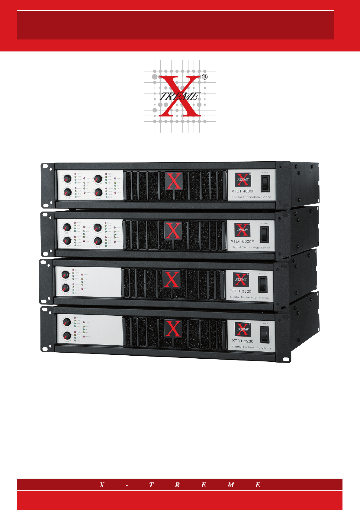
XTDT AMPLIFIERS
XTDT AMPLIFIERS
DIGITAL TECHNOLOGY
AMPLIFIERS
Owner’s manual
1/14
Page 2

Owner’s manual
DIGITAL TECHNOLOGY SERIES AMPLIFIERS
Owner’s Manual
CONTENTS
1. Important safety instructions
2. Declaration of compliance
2.1 User’s liability
3. Introduction
3.1 Unpacking
3.2 Installation/Assembly
3.3 Front panel
3.4 Rear panel
4. Brief description of the product range
5. User instructions
5.1 Maximum power consumption
5.2 Cooling
5.3 Settings
6. Ouput stage block diagram
7. Protection features
7.1 Limiter
7.2 Thermal protection
7.3 Power safety check
7.4 DC protection
7.5. Absorption limitation
7.6 Power supply protection
7.7 Switch-on/Turn-off transients
7.8 Maintenance information
8. Technical features
2/14
Page 3
XTDT AMPLIFIERS
1. Important safety instructions
This symbol indicates the presence of important user instructions
and information that should be given particular attention so as to
use the product properly.
This symbol indicates the presence of “dangerous voltage” that
may cause the risk of electric shock. Pay the utmost attention and
proceed cautiously.
Please, read carefully the following - not thorough -advice for a
correct and safe use of Digital Technology Series amplifiers.
1. Follow carefully the attached documentation and keep it for
future reference.
2. Comply with the warnings.
3. Store the packaging and check that all material is in excellent
conditions.
4. Do not use water near the product, do not pour water or any
other liquid on the amplifiers. Do not use it with wet hands or
feet into the water.
5. Do not use next to heat sources such as radiators, stoves or
other similar devices.
6. Check the integrity of the mains cable. Do not tread on the
cable and do not squeeze the plug.
7. Connect the plug to a socket equipped with grounding. Do not
tamper with the plug. If the plug supplied is not compatible with
your socket, please apply to an electrician for its replacement.
8. Connect to supply mains with the same voltage as indicated
on the back of the amplifier.
9. Install the amplifiers in compliance with the instructions.
10. Do not obstruct the air ducts.
11. Disconnect the appliance in case of storm and if unused.
12. Connect according to the instructions only.
13. Do not connect an input signal higher than that indicated in the
manual.
14. Do not connect the amplifier output to the input of another
channel.
15. Do not connect any output of the amplifier to power sources
such as battery, voltage supply or outlet, regardless of wheth-
er the amplifier is on or off.
16. Keep the volume controls to a minimum during the amplifier
switching on/off.
17. Do not remove the upper or lower cover: there is a risk of elec-
tric shock.
18. Do not try to self-repair the appliance, but apply to qualified
personnel.
19. Clean with a dry cloth only.
20. The product should be handled by skilled personnel in the fol-
lowing cases:
- damaged mains cable or plug;
- exposure of the product to rain or humidity;
- some liquid has entered inside the unit;
- an object has fallen on the unit;
- the unit has fallen down and is damaged;
- the product does not work correctly or shows a remark-
able change of performance.
21. Careful supervision is necessary if the product is used in the
presence of children or inexpert adults.
22. This product could produce sound levels which cause hear-
ing damage. Use the utmost care and do not operate at high
volume level or at an uncomfortable level for a long time.
Consult an audiometric specialist in case of hearing loss or
complaints.
3/14
Page 4
Owner’s manual
2. Declaration of compliance
This device complies with the requirements of the EMC directive
89/336/EEC, amended by 92/31/EEC and 93/68/EEC, and the requirements of the Low Voltage Directive 73/23/EEC, amended by
93/68/EEC.
Standards Applied:
EN55103-1 (Emissions)
EN55103-2 (Immunity)
EN60065, Class I (Safety)
2.1 User’s liability
• Damages to the loudspeaker systems
Always check the peak and continuous power of the loudspeakers. This amplifier is extremely powerful and can be potentially
dangerous both to the loudspeakers and to persons. Most loudspeakers may be easily damaged or broken, especially by amplifiers operating in bridge. Even if there is a gain reduction through
the attenuators on the amplifier’s front panel, it is still possible to
reach the maximum output power if the input signal level is high
enough.
• Dangerous output voltage
The amplifier can generate hazardous output voltage. Do not
touch exposed cables of loudspeakers with the amplifier in operation.
3. Introduction
Congratulations for choosing X-Treme Digital Technology
Series amplifiers and thank you for trusting us and our products.
All the X-Treme amplifiers have been carefully planned in the smallest details, from every part of its equipment to final assembling.
The R&D dpt. underlines that the product you have chosen uses
the most advanced technology. An improper use of the amplifier
can compromise its correct operation. Therefore we recommend
you using it carefully and correctly. Read this manual carefully as
it contains essential information for a safe use of your amplifier.
3.1 Unpacking
Immediately inspect the package and its content so as to check
whether there are any signs of damage. After unpacking check
the product and all parts, if you notice any damage inform your
dealer immediately. It is advisable to save the packaging materials
even if the amplifier shows no sign of shipping damage; you might
have to return it to X-Treme or to one of its dealers. Use the original package only, which is the best way to protect the equipment
from shipping mishandling.
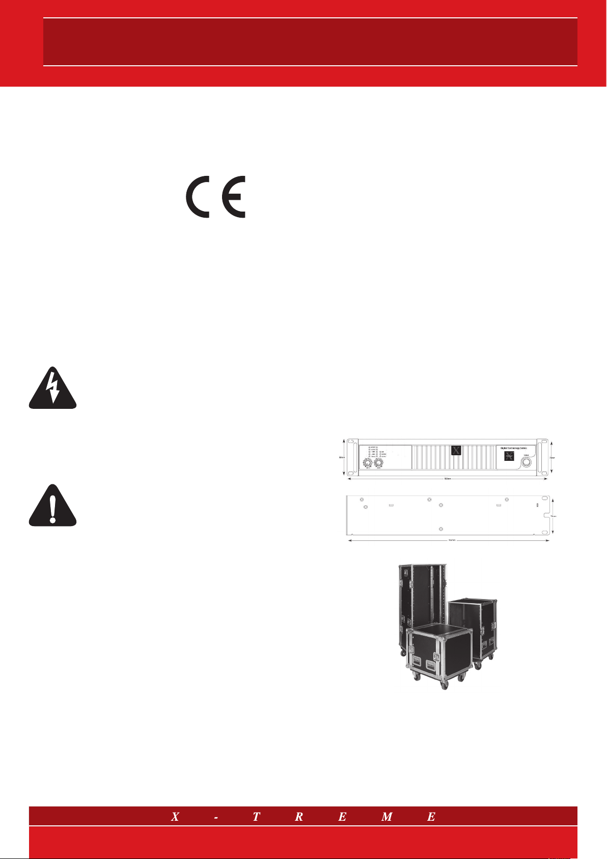
3.2 Installation/Assembly
All models of the X-Treme Digital Technology Series amplifiers may
be installed in a 19’’ standard rack strand. For the assembly 4
holes are present on the front panel; in order to get an optimum
fastening, that is important in movable systems, additional supports are placed on the back.
• Radio interferences
A sample of this product has been tested and approved to meet
the requirements of the Electromagnetic Compatibility Directive
(EMC). These requirements have been defined so as to provide
reasonable protection against dangerous interference of electrical equipment. Whenever this product has not been installed or
handled according to these guidelines, it might interfere with other
equipment such as radio receivers. However, there is no guarantee that they should not occur in a specific installation. Should
this equipment interfere with transceiver equipment (such possibility can be checked by switching on and off the device), the user
should try to cancel the interference by observing one or more of
the following measures:
- increase the distance between the device and the receiver;
- connect the device to a plug linked to a different circuit from the
one to which the receiver is connected;
- redirect or move the receiver’s antenna;
- make sure that the unit concerned conforms to the EMC immunity limits (CE-labelled). All electrical equipment sold in the EC
should be approved concerning the protection against electromagnetic fields, high tension and radio interference;
- contact qualified personnel.
fig. 1
fig. 2
Pay particular attention during the installation; we remind you that
the amplifiers should not be installed in places with:
• high temperatures;
• dust, excessive humidity or water next to the devices;
• presence of strong magnetic fields;
• vibrations;
• enclosed spaces that coud avoid airing.
4/14
Page 5
XTDT AMPLIFIERS
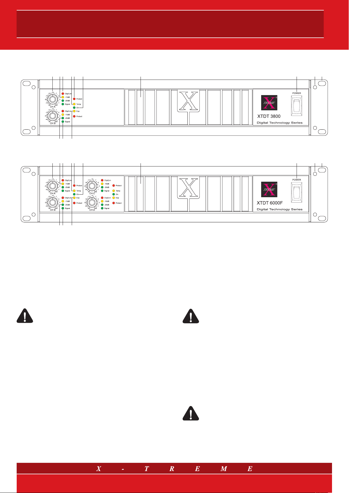
3.3 Front panel: controls and indicators
4 74
1210113 54 6 98
Fig.3 a) Front panel mod. XTDT3200 and XTDT3800
1210113 54 6 98
4 74
Fig.3 b) Front panel mod. XTDT4800F and XTDT6000F
1) Holes for the assembly
2) Holes for standard rack handles
3) Input attenuators
A precision attenuator for every channel with 21 positions allows
tuning of the amplifiers level for every channel.
Warning: when using a mono in bridge both level attenuators A-B (C-D) should be set to the same position.
Please set them to position 0 dB.
4) Signal LED
Every channel has a LED bar that shows the input signal level.
Green LED shows the presence of a signal and level -20 dB, yellow -10 dB.
5) Clip/Limiter LED
Every channel has a LED that lights up at clip point and when the
limiter activates.
6) Protection LED
Protection LED that lights up when the load voltage is under 1 Ω
or the amplifier output has been short-circuited.
Respectively: 0.1%, 1% and 10% of maximum power.
8) Hi-Temp LED
It indicates when the dissipator temperature starts increasing. At
60 ºC the Hi-Temp LED will start flashing and the output power will
be gradually reduced. At 75 ºC the Hi Temp LED will remain lit and
A-B channels (mod. XTDT3200 and XTDT3800) or A-B, C-D (mod.
XTDT4800F and XTDT6000F) will go into mute until the temperature reaches normal level, resetting is automatic.
Warning: this condition usually occurs due to inadequate
ventilation clearance, please check thoroughly the amplifier installation.
9) Active LED
It lights up to show that the amplifier is on and works properly.
10) Starting up push button
A soft-start system limits absorption when starting up.
11) Ventilation grid
Grid with sponge filters for proper ventilation of the amplifier and
to prevent dust infiltration.
Warning: do not block the ventilation entries.
7) Exp LED
It indicates that an optional expansion board has been inserted.
5/14
Page 6

Owner’s manual
3.4 Rear Panel: controls and connectors
fig.4 a) Back panel mod. XTDT3200 and XTDT3800
fig.4 b) Back panel mod. XTDT4800F and XTDT6000F
12) Fan discharge grids
The fan of the cooling system creates an airflow with front/back
directions. The air for cooling the amplifier is taken from the opening on the front side and it is then discharged through the opening
on the back.
Warning: do not obstruct these openings.
13) A.C. Mains cable
Make sure that the cable is undamaged and that the connecting
plug has earth connection.
14) S.N. tag
Every unit has a tag showing: model, power consumption and
serial number.
15) Speakon output connectors
There is a connector for every channel when operating in stereo or
parallel mode. For operating in bridge use Neutrik Combo© connector (refer to fig. 5, 6, 7).
16) Switch for mode setting
Switch to set the usage mode (refer to drawings 5, 6 and 7).
17) Input connectors
Combo© connectors (female XLR with 6.3 mm jack), a connector
for every channel for balanced or unbalanced inputs.
Warning: noises such as buzzing or disturbance on the
loudspeakers may occur when installing wiring next to
dimmer, motors, etc. Balanced connections reduce considerably such noises.
18) HPF and Gain Switch
A 6-position DIP switch to set different gain values and High Pass
Filter for each different channel.
6/14
Page 7

XTDT AMPLIFIERS
4. Brief description of the product range
The Digital Technology Series amplifiers are available in four
models with different power outputs and number of channels.
XTDT3200 and XTDT3800 are two-channel models with a power
supply of up to 1600 W and 1900 W respectively per channel at 4 Ω.
XTDT4800F and XTDT6000F are four channel models supplying
up to 1200 W and 1500 W respectively per channel at 4 Ω.
All XTDT series amplifiers have been fully designed with switching
technology (both the supply power unit section and the power stage)
to obtain high power and performances with a very low weight,
a result which cannot be achieved with traditional configurations.
These features make this series particularly suitable to meet the
typical requirements of the professional audio sector: power, low
weight and high performance (and, therefore, low consumption).
All Digital Technology Series amplifiers are equipped with an
integrated controlled system which protects both the amplifier and
its load. The signal is constantly monitored, with a level control
and indication through a LED on the front panel. An in-built limiter
protects the loudspeakers from any damage caused by distortion
signals. As far as temperature is concerned, the control system
maintains the necessary conditions for a correct operation of
the power components. The output signal control protects the
load from high current values or from the presence of live DC
components. Moreover, the Digital Technology Series amplifiers
contain a selectable hi-pass filter (30 or 75 Hz) designed to adjust
the amplifier to the connected loudspeaker systems.
• Multi-application
• High-technology
• Lightness
• High power & efficiency
only
11 kg!
XTDT3200
Output power @ 2 Ω
Output power @ 4 Ω
Output power @ 8 Ω
only
13 kg!
XTDT4800F
Output power @ 4 Ω
Output power @ 8 Ω
2 x 2000 W *
2 x 1600 W *
2 x 850 W *
4 x 1200 W *
4 x 700 W *
only
11 kg!
XTDT3800
Output power @ 4 Ω
Output power @ 8 Ω
only
13 kg!
XTDT6000F
Output power @ 4 Ω
Output power @ 8 Ω
2 x 1900 W *
2 x 1100 W *
4 x 1500 W *
4 x 850 W *
* EIA 1 kHz - 1% THD - both channels driven @ 230 VAC
7/14
Page 8

Owner’s manual
5. User instruction
5.1 Maximum power consumption
Check whether there is enough power to supply the amplifier
(refer to the data at the end of this manual). Please ensure that
the voltage of the network complies with the instructions found at
the back of the amplifier. Maximum power consumption is limited
solely through the internal fuses.
Warning: before any audio connection keep in mind that
the regular procedure is to turn off the amplifier and to
unplug it from the mains, and set the volume tuners to the
minimum during start up.
5.2 Cooling
Pay particular attention to the ventilation/cooling conditions of the
amplifier. An internal system of forced airflow, by a variable speed
fan, allows cooling of the dissipators from the heat generated by
power parts. The airflow is directed from the front panel to the
back panel of the amplifier, which means that the air is drawn in
from the front and is discharged through the back opening.
Pay particular attention to leave enough space in front of the amplifier to allow the air to go in and enough space at the back to
allow it to come out. If the amplifier is installed in a rack strand,
make sure that there is enough air clearance: air should easily flow
through the amplifier and meet no resistance.
5.3 Settings
Make sure that the equipment is turned off before setting it according to your needs.
It is also possible to set the amplifier for the following functions:
• Gain
One of the main advantages of XTDT amplifiers is the sectable
input gain for each channel, thanks to proper DIP switch that are
placed in the rear pannel. The user is able to calculate the right
Sensitivity value starting from the maximum output voltage and,
obviously, the driven load.
In particular:
V
MAX
V
MAX
Sensitivity (dBu) = V
• Selectable filter for low frequencies
1/2
= (PxZ)
, where P = power and Z = impedance;
(dBu) = 20 log V
/ V0, where V0 = 0.775 V;
MAX
(dBu) - Gain (dB).
MAX
Your amplifier is equipped with an HPF filter that can be selected
for every channel. To set the cutting frequencies use DIP switches
that are placed in the rear pannel of the amplifiers; the cutting
frequencies available are 30 or 75 Hz. When the filter is disabled,
the amplifier will still be protected by the input DC.
• Stereo mode (standard)
When using stereo mode every channel operates independently
and its input attenuators control the respective level.
The minimum recommended load for running in stereo is 2 Ohm
per channel for XTDT3200 and XTDT3800 and 4 Ohm per chan-
nel for XTDT4800F and XTDT6000F (please refer to technical
specifications).
The input signal can be connected by using Combo© connectors
cabled on the back panel. The loudspeakers are linked to the output connectors speakon A-B (C-D) (refer to fig. 5).
fig. 5 a) Stereo Mode mod. XTDT3200 and XTDT3800
Balanced Connection
shie ld
inve rting
non- inve rting
6.3mm (1/4-inch) TRS, XLR
Unbalanced Connection
jump er
6.3mm (1/4-inch) TRS, XLR
jump er
Fig. 5 b) Stereo Mode mod. XTDT4800F and XTDT6000F
• Bridged mono mode
The bridged mono mode is enabled when the Link/Bridge switches on the back panel are set to position “ON”. Using bridged
mono mode implies that A and B (2 Ch.) or A and B, C and D
(4 Ch.) are running with the same input signal, but with inverted
phases. For output power values refer to technical specifications
on paragraph 7.
For bridged mono usage a single input is required for 2 Ch. amplifiers (Ch A or Ch B), whereas for 4 Ch. models Ch C or Ch
D can be selected also, paying particular attention that level attenuators are set to the same position (we recommend position 0
dB). To connect the signal connectors Combo© can be used. The
loudspeakers should be linked to the selected output connector
speakon (refer to fig. 6).
8/14
Page 9

XTDT AMPLIFIERS
fig. 6 a) Bridge Mono Mode mod. XTDT3200 and XTDT3800
Balanced Connection
shie ld
inve rting
non- inve rting
6.3mm (1/4-inch) TRS, XLR
Unbalanced Connection
jump er
6.3mm (1/4-inch) TRS, XLR
jump er
fig. 7 a) Parallel Inputs (Link) mod. XTDT3200 and XTDT3800
Balanced Connection
shie ld
inve rting
non- inve rting
6.3mm (1/4-inch) TRS, XLR
Unbalanced Connection
jump er
jump er
fig. 6 b) Bridge Mono Mode mod. XTDT4800F and XTDT6000F
• Parallel inputs (Link)
The parallel mode is enabled when the Link switches are set to
position “ON”. In parallel mode, the inputs of both channels are
connected and receive the same signal. The input signal should
be connected to Ch A or Ch B for 2 Ch. amplifiers, and also Ch
C or Ch D for 4 Ch. units. Both input connectors Combo© can be
used. Level attenuators work independently, it is therefore possible
to set a different level for every channel. The loudspeakers are linked
to the speakon output connectors A and B (2 Ch. - see fig. 7 a) or A
and B, C and D (4 Ch. - see fig. 7 b)
Please make sure that only the inputs are connected in parallel. Never connect the positive output terminals on earth or parallel.
Warning: always unplug the Link switches when running
the amplifier for Bi-amping.
fig. 7 b) Parallel Inputs (Link) mod. XTDT4800F and XTDT6000F
9/14
Page 10

Thermal Protect
6. Output stage block diagram
CH A input
+
–
-
+
HPF
(30 - 75 Hz)
Owner’s manual
Mute Bus
Multiple
Gain
(26 ÷ 44 dB)
Limiter
Circuit
Error
amplifier
Modulator
Output
stage
driver
Overcurrent
monitor
Half
bridge
power
stage
Fan
controller &
Thermal
monitor
CH B input
+
–
LINK / BRIDGE
dip-switch
+
-
HPF
(30 - 75 Hz)
Clock
generator
and divider
Mute Bus
Clock
generator
and divider
Modulator
Multiple
Gain
(26 ÷ 44 dB)
Vu Meter
Limiter
Circuit
Error
amplifier
Mute Bus
Thermal Protect
fig. 8 Output stage block diagram - XTDT amplifiers
DC
monitor
Power supply
shutdown
DC
monitor
Output
stage
driver
Output
low-pass
filter
Output
low-pass
filter
Half
bridge
power
stage
Overcurrent
monitor
CH A output
1+
2- 2+
1-
1+
2- 2+
1-
CH B output
Fan
controller &
Thermal
monitor
The figure above shows a block diagram displaying the output
stage of XTDT amplifiers (Class D).
XTDT digital amplifiers are provided with a PWM-based technology (Pulse Width Modulation) i.e. the input signal is converted
into a pulse sequence whose output values are higher than the
input ones. Over the time, the average pulse width values will be
directly proportional to the one-point amplitude of the input signal.
The output pulse frequency is typically 10 or more steps higher
than the one-point amplitude of the input signal. A low-pass filter
(LPF) removes the undesired signal components from the modulation spectrum and yields an output signal corresponding to an
accurately amplified version of the input one.
10/14
Page 11

XTDT AMPLIFIERS
7. Protection features
All professional X-Treme amplifiers are equipped with strong protection systems to safeguard the amplifier and its load. These protection systems ensure the power amplifier a long operating life.
7.1 Limiter
When the limiter is ON the CLIP/LIM LED lights up. With the limiter
action the channel gain will automatically lower to protect the load
(loudspeaker systems) from damage caused by signal distortion.
It is not possible to disable the limiter circuit.
7.2 Thermal protection
The temperature state of the dissipator is constantly checked, the
HI-Temp LED gives indications on the temperature status. The HiTemp starts flashing if the dissipater reaches a temperature of 60º
C. In such case the input signal of the relevant channel will be
automatically decreased until the correct running temperature is
reached. If the Hi-Temp LED stops flashing and the light remains
on (anomalous working condition) the whole system will go to
mute until the temperature reaches normal levels.
7.3 Power safety check
On X-Treme amplifiers the output current is constantly checked as
well as the input signal condition. If the current exceeds the maximum allowed level, output tension will be automatically readjusted
in order to assure the amplifiers safety status.
Power safety control acts especially in case of connection to a
load with impedance lower than the recommended levels or if at
the amplifier’s output a non acoustic signal is released during long
periods of time.
7.6 Power supply protection
The AC voltage is monitored; if its value does not fall within the
correct running range (over or under voltage) the supply will be
automatically blocked. The amplifier will restart when the main
supply voltage exceeds the minimum running tension or is under
the maximum running voltage.
7.7 Switch-on/turn-off transients
A mute circuit (without relay), with a delayed starting up and immediate power turning off, has been introduced in order to avoid
the switch-on/turn-off transients that may cause damage to the
loudspeakers.
7.8 Maintenance information
Please contact the nearest X-Treme Assistance Service (Distribu-
tor or Dealer) or directly X-Treme Audio for maintenance assist-
ance.
X-Treme “After Sales Ser vice”
Via Monti Urali, 33
42100 Reggio Emilia (Italy)
Tel. +39-0522-557735
Fax +39-0522-393733
E-mail: service@x-tremeaudio.com
7.4 DC protection
If a value higher than or equal to 7 V occurs, the presence of a DC
on both channels will be monitored indipendently, and the amplifier output stage and the switching supply will be blocked. This
allows loudspeaker protection from the DC.
7.5 Absorption limitation
The X-Treme power amplifiers are equipped with a soft-start system to reduce the absorption when switched on. This feature is
particularly useful in multiple amplifier installations.
11/14
Page 12

Owner’s manual
8. Technical features
• TWO channels
Models XTDT3200 XTDT3800
Power Output (per Channel)
8 Ω 850 W 1100 W
4 Ω 1600 W 1900 W
2.7 Ω 1800 W 2400 W
2 Ω 2000 W /*
Bridged Mono Power
8 Ω 3200 W 3800 W
4 Ω 4000 W /*
(EIA standard 1kHz – 1%THD both channels driven @ 230VAC)
Frequency Response (1W @ 8Ω) 20 Hz - 20 kHz +0/-1 dB
Distortion THD+N <0.1% @ 0.5dB rated power @ 4Ω, 1kHz; 0.4% @ 0.5dB below rated power @ 2 Ω, 1kHz
Distortion SMPTE-IM <0.35% @ -3dB below rated power @ 8 Ω
Signal to Noise Ratio >101 dBA
Damping Factor (@ 8 Ω 10Hz to 200Hz)
Selectable gain 26-44 dB, 3 dB step size
Input Impedance 10 kΩ unbalanced, 20 kΩ balanced
Hum and Noise -100 dB, A-weighted
Input Connectors (each channel) Balanced: Neutrik Combo™, XLR pin 2 and TRS tip positive
Output Connectors (each channel) Neutrik Speakon™
>200
Controls
Led Indicators Active status, signal -35 dB, level -20 dB, level -10 dB, clip/limiter, protect, high-temperature
Amplifier Protection
Load Protection On/off muting, clip limiter, DC-fault power supply shutdown
Circuitry Digital Technology - Class D amplifiers
Power Supply Regulated global power supply (95 - 265VAC) works anywhere in the world with PFC
Cooling Continuously variable fans, front to rear air flow with front panel dust filter
Power Requirements 95 - 265 VAC, 50-60 Hz
Approvals CE EN55103-1 (Emissions), EN55103-2 (Immunity), EN60065, Class I (Safety)
Current Draw (230 VAC)
1/8 power 4 Ω 3.2 A 3.7 A
1/3 power 4 Ω 6.5 A 7.6 A
at idle 0.5 A 0.5 A
Dimensions (WxHxD) 483 x 88 x 455 mm
Net Weight 11.5 kg 11.5 kg
* The amplifier will be fully operational at 2 Ohm loads (or bridge mode at 4 Ohm), but, due to physical constraints, the hi-temp protection may occur, limiting the maximum
output power to values surely not higher than those obtained using the device at 4 Ohm loads (or bridge mode at 8 Ohm).
Front: power switch, Ch.A, Ch.B stepped gain knobs
Rear: 2/6-position DIP switch
Full short circuit, open circuit, thermal, ultrasonic and RF, continuous non-musical signals,
reactive or mismatched loads, mains AC outside the operating voltage
XTDT3200 XTDT3800
12/14
Page 13

XTDT AMPLIFIERS
• FOUR channels
Models XTDT4800F XTDT6000F
Power Output (per Channel)
8 Ω 700 W 850 W
4 Ω 1200 W 1500 W
2.7 Ω 1550 W 1800 W
2 Ω /* /*
Bridged Mono Power
8 Ω 2 x 2400 W 2 x 3000 W
4 Ω /* /*
(EIA standard 1kHz – 1%THD both channels driven @ 230VAC)
Frequency Response (1W @ 8Ω) 20 Hz - 20 kHz +0/-1 dB
Distortion THD+N <0.1% @ 0.5dB rated power @ 4Ω, 1kHz; 0.4% @ 0.5dB below rated power @ 2 Ω, 1kHz
Distortion SMPTE-IM <0.35% @ -3dB below rated power @ 8 Ω
Signal to Noise Ratio >101 dBA
Damping Factor (@ 8 Ω 10Hz to 200Hz)
Selectable gain 26-44 dB, 3 dB step size
Input Impedance 10 kΩ unbalanced, 20 kΩ balanced
Hum and Noise -100 dB, A-weighted
Input Connectors (each channel) Balanced: Neutrik Combo™, XLR pin 2 and TRS tip positive
Output Connectors (each channel) Neutrik Speakon™
>200
Controls
Led Indicators Active status, signal -35 dB, level -20 dB, level -10 dB, clip/limiter, protect, high-temperature
Amplifier Protection
Load Protection On/off muting, clip limiter, DC-fault power supply shutdown
Circuitry Digital Technology - Class D amplifiers
Power Supply Regulated global power supply (95 - 265VAC) works anywhere in the world with PFC
Cooling Continuously variable fans, front to rear air flow with front panel dust filter
Power Requirements 95 - 265 VAC, 50-60 Hz
Approvals CE EN55103-1 (Emissions), EN55103-2 (Immunity), EN60065, Class I (Safety)
Current Draw (230 VAC)
1/8 power 4 Ω 4.5 A 5.5 A
1/3 power 4 Ω 9.5 A 11.5 A
at idle 0.5 A 0.5 A
Dimensions (WxHxD) 483 x 88 x 455 mm
Net Weight 13.5 kg 13.5 kg
* The amplifier will be fully operational at 2 Ohm loads (or bridge mode at 4 Ohm), but, due to physical constraints, the hi-temp protection may occur, limiting the ma ximum
output power to values surely not higher than those obtained using the device at 4 Ohm loads (or bridge mode at 8 Ohm).
Front: power switch, Ch.A, Ch.B stepped gain knobs
Rear: 2/6-position DIP switch
Full short circuit, open circuit, thermal, ultrasonic and RF, continuous non-musical signals,
reactive or mismatched loads, mains AC outside the operating voltage
XTDT4800F XTDT6000F
13/14
Page 14

Contacts
www.x-tremeaudio.com
X-Treme Headquarters:
via Monti Urali, 33 - 42100 Reggio Emilia - Italy
tel. +39 0522 557735
fax +39 0522 391268
X-Treme Audio reserves the rights to change or modify products and specifications at any time without prior notice.
X-Treme and the corresponding symbols, images and registered trademarks are of exclusive property of Sound Corporation group. © 2010 Sound Corporation group. All rights reserved.
14/14
For technical support/information: support@x-tremeaudio.com
For general information: info@x-tremeaudio.com
For commercial information: sales@x-tremeaudio.com
 Loading...