

Page 1
LINE ARRAYS
LINE ARRAYS
User’s manual
1/21
Page 2

User’s manual
LINE ARRAYS
User’s manual
CONTENTS
1. Free-field acoustics
2. Sound power and pressure levels
3. Physical-mathematical model: brief description
4. Linear sources: introduction
4.1 Infinite length linear source
4.2 Finite length linear source
5. Description of the sound field of a linear source
5.1 Directivity analysis
5.2 In-axis response analysis
6. Arc, J and progressive sources
7. Line arrays: “the state-of-the-art”
8.
X-Treme Vertical Line Array: product range
9.
X-Treme Vertical Line Array
10. MISITM system: from “AS IS” to “TO BE”
11. Types of installations
12. Stacking instructions
13. Suspension guidelines
13.1 X-Treme Installer (XTI)
13.2 Suspension instructions
: system design
13.3 “Straight to the… angle”
13.4 LSA: flying and lifting
1. Free-field acoustics
An unlimited acoustic space without discontinuities or obsta cles
can be defined as a “free-field” and clearly is an idealization of
the real conditions in which the sound usually propagates itself,
whether it is generated by a “natural” source or by a sound re inforcement system. However, this can lead to two situations in
which the free-field conditions may be approximated in a more or
less correct way. The first one refers to an open space (such as
an area where great events and rock, pop music concerts can
take place) provided that weather conditions are stable and homogeneous, and no surfaces or obstacles are found in a suitably
large area all around the source. The second one can be created
artificially in a laboratory with special conditions, known as “ane-
choic” chamber, where all the surfaces limi ting it absorb completely the sound acting on them; the sound inside the chamber
is just the one produced by the source, as no sound is reflected
by the surfaces.
The acoustic field generated by a source in free-field conditions
can be schematically divided into two regions: the so-called near
field and the far field. In the first region of the acoustic field the
sound intensity can have a complex trend depending on the type
of source (see the following section about linear sources) and on
its dimensions, which does not necessarily follow a mo notonic
trend in relation to distance; moreover, the source directionality
characteristics should be carefully examined.
In the second re gion, from the near field to infinity in theoretical terms, the sound intensit y shows instead a linear trend and,
as is well-know, it is inversely proportional to the square of the
distance from the source; in other words, the sound inten-
sity level (defined as the quantit y of energy that flows, per time
unit, through a unitary surface area which is perpendicular to
the wave pro pagation direction. Unit of measurement: Watt per
square metre) decreases by 6 dB for each doubling of distance
(the so called “inverse-square” law). In addition to this, the
source directivity can be determined in an univocal and welldefined manner.
The far-field condition occurs when the values of the distance r from
the source meet all the following conditions:
r >>λ/2π , r >> L , r >> πL2/2λ,
13.5 MISITM and MLA: enclosure suspension rigging
14. Subwoofers
15. Tri-amplification system configuration
16. System configurations: standard examples
16.1 Linear Source Array
16.2 MISI
16.3 Mini Line Array
TM
where L is the largest linear dimension of the source, λ is the longest wavelength (therefore the lowest frequency) of the sound emit-
ted by the source (therefore λ is always ≤ 17.2 m - f ≥ 20 Hz) and the
“much higher” symbol means at least 3 times higher (Bies, Hansen
1988).
Note: a free-field variant is the so-called “free field on a reflect-
ing surface”, such as a large open space on a rigid and highly
reflecting surface (e.g. asphalt, ground) or a made-to-measure
special environment known as “semi-anechoic” chamber. An
omnidirectional source located near a reflecting surface acts as
if it was associated to an image source having the same sound
power: as a result, the intensity at every point of the acoustic
field is worth double the sound intensity generated by the same
source in a free field, therefore the intensity level will be 3 dB
higher.
2/21
Page 3
LINE ARRAYS
2. Sound power and pressure levels
At present, one of the most common and interesting problems to
face is the following: let the sound power (or the sound power level)
of a certain source be given, a magnitude that characterizes it intrinsically, determine the sound pressure (or the sound pressure level)
at any point of the space where the source works. In a free field
or in a free field on a reflecting surface, this problem can be easily
solved by calculating all the necessary elements with the following
simple formula:
Lp = Lw + ID
- 20 log(r) - 11 [dB].
θ,ϕ
Therefore this relationship, which is valid in far-field conditions (in fact,
in this case all the real acoustic sources smaller than the wavelength
of the sounds they produce can be approximated as pulsating point
spheres known as “monopoles”), enables the calculation of the sound
pressure level Lp produced by a source having a sound power level
Lw (=10 log W/Wo with Wo= 1 pW; e.g. if the acoustic power of a speaker system is 100 W its sound power level will be 140 dB), at a certain
distance r in a direction such that the di rectivity index of the source is
ID
(=10 log Q
θ,ϕ
with Q
θ,ϕ
being the direc tivity factor of the source in the
θ,ϕ
direction identified by angles θ and ϕ).
For example, a source with a sound power level of 120 dB (therefore with power W equal to 1 Watt) and a directivity index of 3
dB in the direction where the listener is positioned, produces a
sound pressure level of 84 dB in a 25 m far free-field, because:
Lp = 120 + 3 - 28 - 11 = 84 dB.
Furthermore, if we know the sound pressure level Lp1 at a certain
distance r1 from the source (for example, by measuring it through
a sound-level meter) and in a certain direction, the sound pressure
level Lp2 can be determined at another distance r2 in the same direction, without necessarily knowing the sound pressure level.
In fact, by using the equation above, we obtain:
Lp2 = Lp1 - 20 log(r2/ r1) [dB].
If, for example, a source produces a sound pressure level Lp1 =
92 dB at a distance r1 = 8 m, the sound pressure level at r2 =16 m,
in the same direction, will be 86 dB (as mentioned at the beginning, the sound pressure level decreases by 6 dB when distance
doubles).
Note: in a free-field on a reflecting surface, in the semi-space where
the source is forced to radiate, as previously mentioned, the sound
intensity is twice the intensity existing in a free field. Therefore, 3 dB
should be added to the sound pressure level calculated with the
formula above.
3. Physical-mathematical model: brief description
Most acoustic models are simplified solutions of a general equation
(wave equation) which are subject to certain “constraints”, such as
the environment’s volume or its known value at certain points in the
listening space. Therefore, in an acoustic study the used formulas
are a small set of specific solutions which is almost suitable for describing with sufficient approximation the acoustic field in a listening
environment. In general, these solutions are expressed in terms of
pressure in relation to space and time variables.
In indoor acoustics, the space characteristics are modelled as
boundary conditions and they exert a remarkable influence on the
acoustic field. It is the physical dimension of the space that makes
the presence of waves with a certain length possible (or impossible). In mathematical terms this falls within the category of the
eigenvalue problems. The solutions will be strictly dependent on
frequency and will have periodical behaviours (in acoustical terms
this is the so-called modal theory).
On the contrary, in outdoor acoustics, the boundary conditions
imposed on the wave equation will commonly be radiation conditions, which are necessary to make the mathematical model coherent with the physical reality. The dependency on frequency is no
longer regular as it occurs in closed spaces and the modal theory
cannot be applied. Of course, the differences between open and
closed spaces affect sound reproduction and the ability of a speaker system to adjust to different reproduction contexts, especially if
we consider the wide range of problems arising in open spaces.
Line arrays can solve the various problems associated with
sound reproduction. In this short introduction we will analytically
describe a line array mathematical model and we will com ment
on a few important results deriving from this model. Finally we will
demonstrate that a simple theoretical model can suitably meet
the coherence requirements with real measurement. This short
introduction, having an analytical and general character, will not
deal with the problems concerning the technological features of
the models (waveguides, etc…) or with the electro-acoustics solutions that are nevertheless essential for designing and producing line arrays.
4. Linear sources: introduction
Generally speaking, real sound sources are very complex and it
is quite difficult to describe them in detail. Luckily, in most practical cases, we can resort to substantial simplifications. The most
drastic one, as previously mentioned, consists of considering a
real source as an infinitely small point source whose dimensions
are actually much smaller than the wavelength λ of the reproduced
sound and/or if the listener is at a great distance from the source
position. However, other more complex ideal sources can better
represent the properties of the real sources: it is the case of the
linear sources, namely point sources that are conveniently arranged along a straight line, which are used in the literature to
exemplify a stacked or flying vertical line array system. A row of
cars along a straight road is another more common example of a
real source which can be approximately represented as an infinite
length linear source.
Line source
b=step
n
...
W
0
3
W
0
2
W
0
1
90°
r
0
β
η
P
fig. 1
3/21
Page 4
User’s manual
4.1 Infinite length linear source
With reference to fig. 1, let’s imagine an infinite sequence of unrelated
sources, spaced out by a distance b and all having the same sound
power Wo. As a result, the intensity of each source adds up to that of
the other sources in determining the total intensity at the distance ro in
a normal direction towards the linear source. Working from this hypothesis, we can demonstrate (Beranek, 1988) that with a distance value
ro >= b/π
and therefore at a distance such that the individual sources cannot
be distinguished one from the other, the average sound intensity
can be simply approximated by the relationship:
〈I〉=Wo/4bro [W/m2].
In other words, at distances exceeding the distance between one
source and the next (these are exactly the listening conditions of the
vertical line array sound reinforcement systems, since the distance between the elements is generally one linear metre) the intensity no longer varies with the square of the distance as in the case of
the monopole sources, but is inversely proportional to the distance.
This means that these sound waves (often known as cylindrical)
decrease by just 3 dB for each doubling of the distance rather than
by 6 dB as it occurs in traditional systems (the previously mentioned
“inverse-square” law).
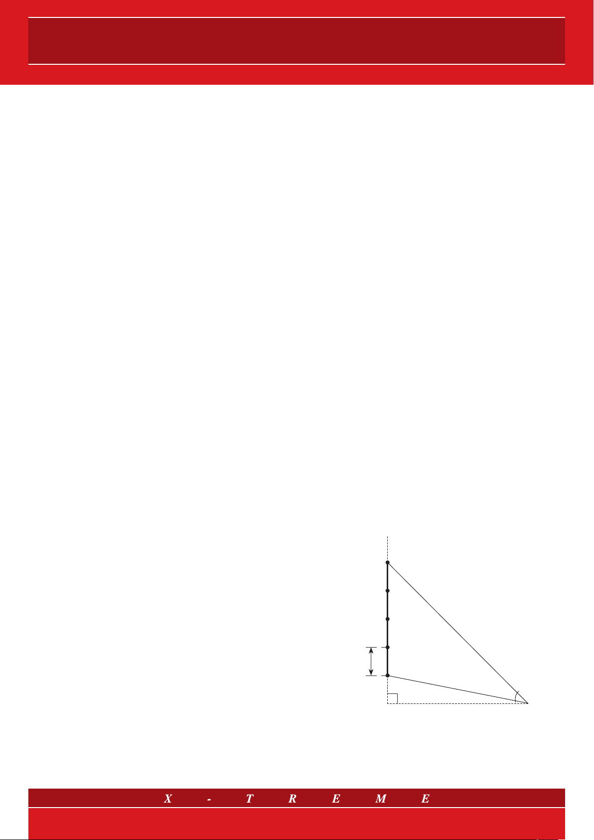
4.2 Finite length linear source
If the sources arranged on a line are in a finite number n (>=3) and
βn is the angle, in radians, below which the source line is seen from
the observation point (as indicated in fig. 1), always at sufficiently
large distances (ro >= b/π), the sound intensity can be determined
according to the following relationship:
〈I〉 = Wo·βn /4πbro [W/m2].
In this case too it is inversely proportional to the distance and,
obviously, it is directly proportional to the angle opening below
which the linear source is seen from the listening point. In conclusion, in this case, one can state that a reasonably accurate description of the ver tical line array behaviour has been reached,
which is approximated as a finite linear source in its near field.
In fact, owing to the di mensions of the magnitudes at issue, the
b/π limit beyond which the array can be approximated as a linear
source (and therefore it can be seen as a source of cylindrical
waves) is much smaller than the above-mentioned limit between
a far field and a near field (it should be recalled that this limit is
represented by the larger distance between the following ones:
r >>λ
/2π, r >> L , r >> πL2/2λ
max
max
).
5. Description of the sound field of a linear source
In order to analyse the sound field generated by a line array let’s
start from a simple and ideal model: the finite linear source (or
line source).
Far field
Line source
L/2
dl
x
dl sin(α)
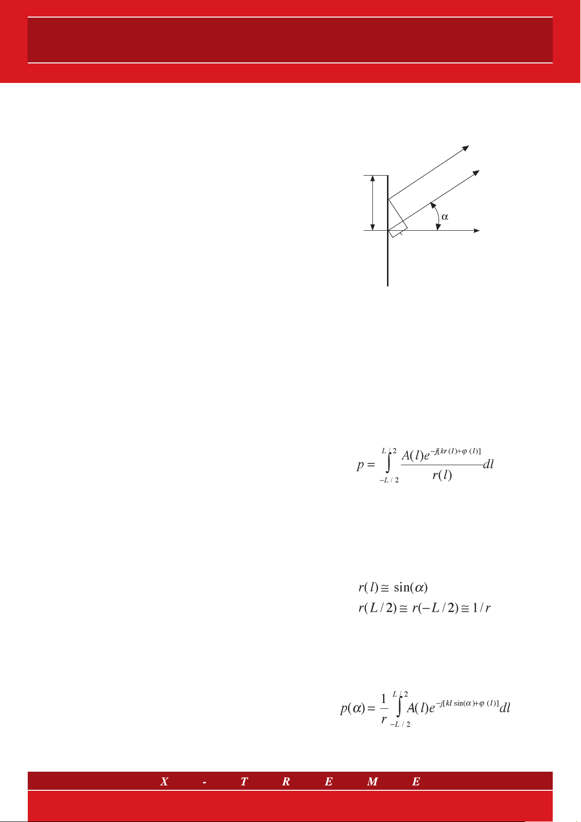
fig. 2
The sound pressure generated by a linear source can be obtained analytically as a special solution of the wave equation,
in relation to space and time coordinates. Moreover, it is also
assumed that the source can only emit a sinusoidal signal. From
a mathematical viewpoint, this simplification allows us to use a
notation (known as phasorial) which simplifies calculations and
ensures completeness without losing its general character. The
Fourier theory shows that, within some hypotheses (which have
been widely verified in the case of musical signals), any periodical
signal can be modelled as the sum of individual sinusoids.
Having said this, we can therefore express the sound pressure generated from a linear source as:
where L is the line length, k is the wave number, A(l) and ϕ (l) are
the signal amplitude and phase respectively on a point of the line (or
rather on an infinitesimal segment dl) at a distance r(l) from a generic
observation point or, rather, from a listening point P.
In order to analytically verify the line array properties, a few additional hypotheses are required. For example, it can be easily noticed that, beyond a certain observation (or ‘listening’) distance,
one will have:
Note: some empirical formulas can be found (Smith, Heil and
others) in which the border distance from the near to the far
field depends on variables such as the array length or the
reproduced frequency. However, it is better not to use them
as they lack any general validity!
In the far field, on the contrary, it is right to apply the considerations
mentioned just few lines earlier about the “inverse-square” law. In
particular, in the case of linear sources, since the sound power of a
single source Wo is known, the formula used to calculate the sound
pressure level in the free-field conditions on a reflecting surface will
be:
Lp = Lwo + 10 log(βn /r) – 8 [dB],
where βn is the angle below which the sources are seen from the
listening point.
This further condition is precisely that of the far field, as previously
mentioned.
Thanks to the far field hypothesis we can rewrite the final expression
of pressure in a form that we will use to evaluate the source directivity (see paragraph 5.1):
4/21
Page 5
LINE ARRAYS
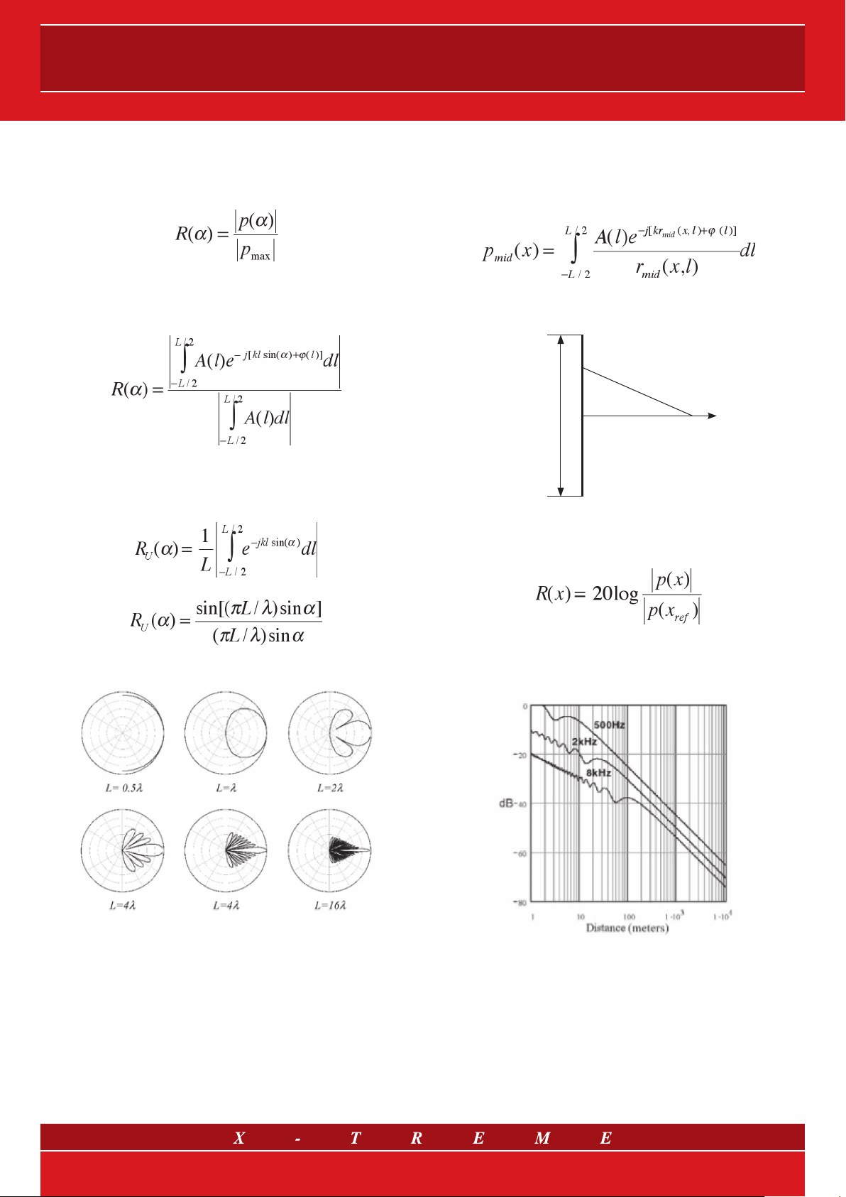
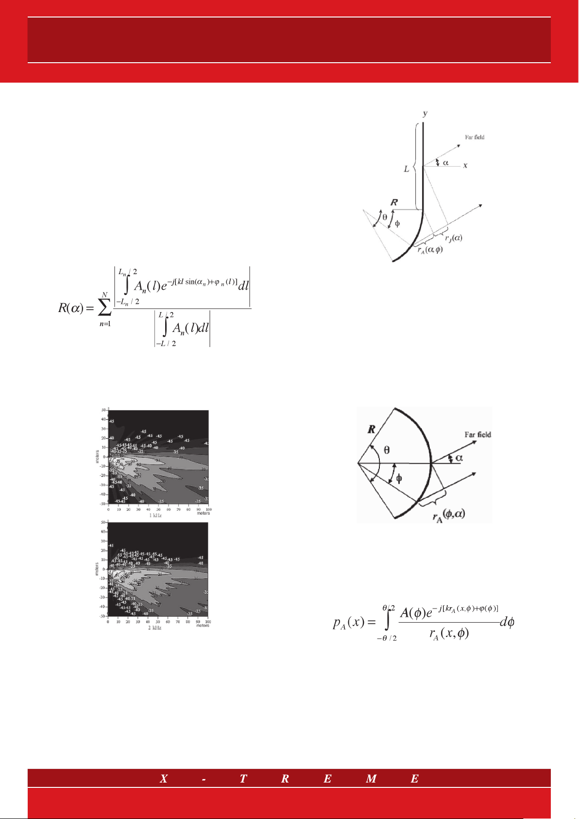
5.1 Directivity analysis
The directivity function enables us to evaluate the pressure distribution in relation to a definite emission direction. By using again the
formulas of fig. 2, the directivity function R(α) can be defined as:
where
p
is the pressure in the maximum emission direction, in
which from a mathematical viewpoint the exponential function below the integral sign assumes the maximum value (= 1). Following
what has been stated above, one can obtain:
In order to have a qualitative representation of the linear source
directivity, take into account the simplest situation (the so-called
uniform linear source) with a constant amplitude (A(l)=A) and null
phase deviation (ϕ=0). One will have:
max
5.2 In-axis response analysis
Similarly to the directivity analysis, and referring to fig. 2, we force the
(observation or “listening”) point P to lie on the axis x. Now let’s go
back to the general case, thereby excluding the far-field hypothesis.
The pressure form will therefore be of the following kind:
where r
The corresponding directivity function on the x axis is often expressed in a logarithmical form:
(x,l) is the distance traced in fig. 4
mid
Line source
r
dl
L
mid
fig. 4
(x,l)
P
mid
(x)
x
p
whose solution is:
rendering the wavelength λ explicit from the expression of the wave
number k.
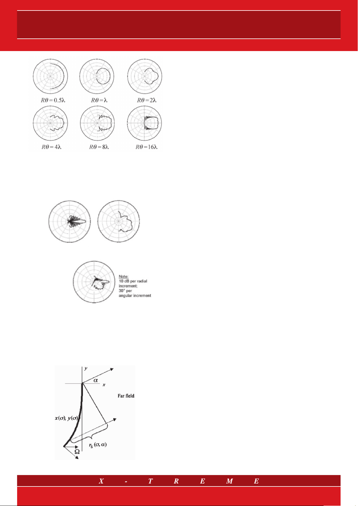
fig. 3
Figure 3 shows the polar diagrams of function RU(α).
Let’s consider the L/λ ratio (0.5, 1, 2, 8, 16), i.e. the ratio between
the line length and the wavelength. It can be easily noticed that a
very high directivity is obtained in wavelengths that are much shorter (1/8, 1/16) than the line length (in the specific case of a few metre
long line arrays, this leads to mid-high frequencies). In other words,
in the case of a linear source, the narrower the main emission lobe
is, the better the sound energy transmission can be forced into a
narrow and orientable corner of the sound front.
Where x
Note that R(x
case of a 4 m long uniform linear source (as already seen in A(l)=A and
ϕ= 0), will have a qualitative trend of the type shown in fig. 5
Each curve refers to a certain sinusoid frequency. A double slope is
observed for each curve: as the distance from the source grows, at the
beginning there is a decrease of 3 dB for each doubling of the distance,
then there is a decrease of 6 dB for each doubling of the distance.
The (theoretical) point in which the curve changes its slope is called
transition distance and it is a function of both the fre quency and the
dimension of the line source (L). The branch with a -3 dB slope is the
near field, that with a -6dB slope is the far field.
is a reference distance, generally 1 m.
ref
)=0. The double logarithmic graph of r(x), in the specific
ref
fig. 5
5/21
Page 6
User’s manual
Therefore, in a linear source the in-axis response decreases by 3
dB for each doubling of the length instead of 6 dB as it occurs in a
con ventional speaker system (point source) until the transition distance is reached, which at medium-high frequencies can be dozens
of metres for sources just a few metres long.
6. Arc, J and progressive sources
In a real configuration the wavefronts generated by the line array
should be adjustable to the variables of the listening space (number
and position of the listeners, listening space morphology, stage
dimensions) to reach, in theory, the maximum listening uniformity
from different positions.
The general formulation of the directivity function, in case of N dif-
ferent sources, sums up the effects of these N (linear or not) sources
— the resulting function is as follows:
Given the freedom levels, this type of model can de scribe some
real situations in a simplified way, such as those in fig. 6, relating to
the measurement of a typical musical event with a line array sound
reinforcement system.
fig. 7
The formal calculation of the expressions relating to the J source,
despite having been substantially simplified, requires superfluous
complex steps. On the contrary, the qualitative analysis of the contribution to directivity given by the lower semi-arc is quite interesting.
Similarly to the considerations made for the linear source, an ideal
arc source model can be created and the pressure expression can
be analysed.
fig. 6
The directivity diagram as shown in fig. 6 can be used to approximately represent a specific case of the suggested general for mula,
where the sum has been reduced to two terms. The mathematical sum of these two terms represents the overlapping of half an
arc source (which will be analytically described later) and a linear
source. The resulting model is an important one, called J source.
Fig. 7 provides a further explanation of the link between the model
we are trying to improve with the analytical description and the line
arrays.
fig. 8
Skipping the mathematical steps required to replace the variables
below the integral sign, we can write down directly the expression
of the acoustic pressure as:
from which the directivity function is obtained.
A qualitative analysis of the polar diagrams of the arc source,
indicated in fig. 9, reveals the same dependency between the lobe
distribution and the frequency/arc length ratio noticed in the case of
the linear sources. As far as linear sources are concerned, however,
a greater width of the main lobe is observed as one can clearly see
from the polar pattern chart in the following figure.
6/21
Page 7
LINE ARRAYS
fig. 9
As a result of this property of arc sources, taking into account the
lower semi-arc only and adding a linear source, one can see (fig.
10) that the J source model is suitable to describe the sound field
represented in fig. 6.
Line source Arc source
J source
7. Line arrays: “the state-of-the-art”
The term “line array” (also called “sound columns”) applies to a
sound reproduction system made up of a variable number of vertically arranged units (also called modules), which can achieve the
effect of a single acoustic source having the dimen sions of all the
component units and whose performance provides a coherent reproduction, that is the result of the sum of its various compo nents.
The vertical alignment allows narrowing of the reception zone to be
achived as well as greater directivity and sound pressure compared
to traditional systems.
The idea is to create columns made up of low, middle and high frequency speakers; the systems consist of small, light modules joined
into a wide acoustic source - the “line array”. The main advantage of
this type of system is the energy saving deriving from narrowing the
vertical directivity and a higher directivity of the sources which can
also produce sound waves decreasing by 3 dB only for each doubling of distance instead of 6 dB as happens in traditional systems.
These types of waves are defined as cylindrical and are generated
while respecting certain parameters relating to the elements making
up the array within a certain distance from the source (near field ),
which depends on the frequency of the reproduced wave and on
the lenght of the source itself. Having only two dispersion dimensions instead of three as in traditional spherical waves, the sound
transmitted by the cylindrical waves decreases much more gradually in relation to the distance from the source. As a result, the listening experience does not change significantly in terms of sound level
from a position far from the line array source to a position very near
to it. Moreover, the vertical radiation for this type of system decays
rapidly above and below the line array. As a result, less reverberation is generated in case of indoor use because no wave is radiated towards any reflecting surfaces existing in the upper part of the
room. Consequently, clarity and sound intelligibility are remarkably
improved.
fig. 10
The J source model can be generalized in the progressive source
(fig. 11), where the curvature is no longer null (or, better, infinite) and
then constant such as in the J source, but it is parametrized in relation to a coefficient σ. The analytical formulation is even more complex than the arc source but it is clear that a progres sive source can
achieve complete control of the emission lobes.
8. X-Treme Vertical Line Array: product range
Created in 2001, the X-Treme brand identifies all the products man-
ufactured by the Sound Corporation group business unit which
produces “concert, touring and portable sound systems”, that is
professional audio systems for concer ts, open air “live” events or
any other indoor installation where music is played live.
The X-Treme SBU (Strategic Business Unit) catalogue presents 3
different lines of vertical line array (VLA), all consisting of a 3-way
module (the bi or tri-amplification mode can be selected by switching the high current handling terminals in the crossover) and its corresponding stacked or flying subwoofer, available in both active and
passive versions.
The Linear Source Array (LSA) system is the top solution of the
range: in particular, the XTLSA module features high performances
in terms of acoustic pressure as well as an innovative horn-loaded
midrange configuration; the
system has been designed to achieve an acoustic pressure similar
to that of the above-mentioned “big” system, but with a higher response speed. Finally, the Mini Line Array (MLA) system stands
out for its exceptional sonic accuracy with extremely reduced bulk
and weight.
MISITM (Middle-Sized Line Array)
fig. 11
7/21
Page 8

User’s manual
Self-powered systems
The Linear Source Array XTLSA/A, MISITM XTMISI/A and Mini Line
Array XTMLA/A active modules have been designed with the purpose of offering highly professional products combining the X-Treme
audio system quality with new digital electronics technologies for
the audio sector: in fact, both the power stage and the power supply unit have been entirely designed with switching technology to
achieve high performance with very reduced weight.
The signal quality, in terms of distortion, is the same of that of the
traditional professional amplification systems, while the pre-amplification stage uses a powerful DSP (Digital Signal Processor)
which allows extremely accurate processing of the signa l as well
as the implementation of complex algorithms in infinitesimal times.
In particular, the system management is innovative and accurate
thanks to the remote connection thus enabling the creation of
speaker system networks which can be controlled by a single station. The X-Treme designers’ efforts have led to the development of
very interesting products for those working in the professional audio
sector and appreciating continuous technological improvements.
9. X-Treme Vertical Line Array: system design
The X-Treme vertical line array (VLA) acoustic speaker systems
have been designed to achieve broad horizontal and vertical coverage. This has been obtained thanks to a new waveguide for
high range selection capable of producing a 120° coverage on a
horizontal plane. Star ting from an array made up of side-by-side
X-Treme speakers, the cabinets can be progressively opened by
using the rear bars and by selecting the hole that ensures correct
positioning, to obtain an array with different curvatures. A linear
array can be created by using the hole corresponding to the lowest position in the rear of the cabinet handles. All X-Treme VLA
loudspeaker systems have been designed as systems composed
of identical elements in a vertical array configuration.
When different loudspeaker systems (often called ‘line array mod-
ules’) are configured in a line array, the electro-acoustic transducers
are placed inside the cabinets in order to meet the Wavefront Sculp-
ture Technology© criteria for each frequency band (1. the wave fronts
generated by the electro-acoustic transducers for high frequencies
are planar, 2. the “step”, that is the distance between acoustic centres of the individual mid-low frequencies sources is smaller than half
the wavelength correspon ding to the highest reproduced frequency
= cut-off freq.).
Therefore, each element generates a linear wave-front with
a constant phase which enables several eleme nts to be assembled together creating a single broad sound source. Since
the separation angle between the elements is adjustable, the
wave-front can be modelled by changing the shape of the array.
Thanks to a successful coupling right across the audible spectrum, the X-Treme VL As generate a coherent wave-front on a
large area with tiny variations in frequency response and sound
pressure level. Therefore, these products are broadband sound
reinforcement systems which ensure coherence up to the highest frequencies. In terferences may occur as in all loudspeakers
systems, but what makes X-Treme different is that interferences
are constructive in the declared coverage area, and destructive
outside this area. In a line array configuration, the bulk of the enclosures is smaller because all the array elements are coherently
coupled, and fewer cabinets are required compared with conventional systems.
This means that the VLAs are highly competitive in case of touring
applications in which transport, space availability and assembling can
be very expensive. These properties make these systems very convenient even for fixed installations where compact dimensions and
coverage predictability are essential factors. In fact, one of the key
benefits of the line arrays is predictability of the wave-front shape.
Besides coverage accuracy, another important advantage resulting
from using X-Treme array systems is their ability to extend the near
field at high frequencies.
In linear arrays, this leads to SPL reduction by 3 dB for each doubling
of the distance versus 6 dB in the traditional systems. This property
results from the physical features of cylindrical waves and spherical
waves. This also means that these systems should not be evaluated
on the basis of the classic “cost/kilowatt” ratio — since they gener-
ate flat wave-fronts, they follow different attenuation laws compared
with traditional systems. Determining the SPL value according to
standard calculations is not meaningful because VLAs generate a
combination of cylindrical and spherical wave-fronts which must be
evaluated according to specific models (as shown in paragraph 4).
X-Treme curved arrays
When curved arrays are used, a combination of cylindrical and
spherical propagations is obtained. Although the propagation of
pure cylindrical waves does not always occur, reduction by 3 dB
in relation to distance can be achieved through the extension of
the near field and correct orientation of the system on the listening
area. From a psycho-acoustic perspective, the near field extension
allows the listener to be at a great distance from the systems and
to perceive just a small difference in SPL terms due to the non conventional attenuation. In practice, the result is a high fidelity listening
expe rience, a better stereophonic image and exceptional clarity. At
a subjective level, listeners feel that the speaker systems are closer
to them and that the sound is “right on your face”. The sound image
localization is towards the stage, rather than towards the speaker
systems. The near-field extension implies that not very high sound
pressure levels are required near the system in order to obtain suitable SPLs at the back of the listening area. Moreover, this property
reduces the potential hearing loss for the audience and technicians
alike. The near-field extension, combined with the coverage accuracy and predictability, can also effectively increase the critical
distance in highly reverberating spaces (critical distance can be
defined as the distance to which the direct sound energy equals
that of the reflected sound). In many situations it is very important to
prevent signals from reaching the ceiling, which means preventing
energy from reaching any reflecting surfaces which have no relation
with the sound event, such as in sports halls, arenas or amphitheatres. Having less reverberation resulting from the sound acting on
empty rooms or reflecting surfaces and by directing more energy
to the listening area, critical distance can be increased in a specific
room. Finally, another benefit of X-Treme VLA systems is the high
decaying SPL level outside a well-defined wave field. This allows
installation of the arrays behind or on top of the microphones with
an exceptional resistance to feedback. Basically, if the bottom of the
last module is visible, it means that one is outside the system coverage field. The FOH technicians too will prefer working with these
loudspeaker systems for their low back-propagation, even at low
frequencies, as the woofers will be positioned in a vertical array.
The high SPL attenuation levels outside the coverage area make
X-Treme VLAs an excellent solution for situations in which environmental noise should be avoided, such as, for example, in open air
amphitheatres located near residential areas.
8/21
Page 9

LINE ARRAYS
10. MISI
The MISI
TM
system: from “AS IS” to “TO BE”
TM
(Middle-Sized line array) vertical line array can be de-
fined as a suitable compromise between power, weight and size.
The designers of the MISITM system aimed to create a series of line
array speakers capable of achieving considerable sound coverage
with reduced bulk and weight. As a result, the system is particularly
suitable for both middle-large tours as well as indoor and outdoor
fixed installations.
The MISI
TM
system provides the right solution to the needs of those
working in the live sector and/or dealing with sound reinforcement
of large spaces. Each loudspeaker system offers 120° coverage
horizon tally and 15° coverage vertically. The trapezoidal enclosure
corners of the XTMISI unit have been designed so that a 2 x 7.5° angle is achieved when two loudspeaker systems are set side by side.
Thanks to the suspension mechanics, starting from an array made of
side-by-side XTMISI modules (7.5° x 2 = 15° between the different
cabinets), the various cabinets can be progressively “opened” by us-
ing the rear bars and selecting the hole ensuring correct positioning, in
order to obtain arrays with different curvatures (fig. 12). The mechanical
suspension system designed for the vertical line array module XTMISI
allows the angle between two speakers to be adjusted, with a 1° resolution, from 0° to 15°, corresponding to two side-by-side loudspeaker
systems and a line array respectively.
Array curvature
adjustment system
On a horizontal plane, the whole line array, made of different XTMI-
SI modules, shows the same directivity as a single element (120°).
On a vertical plane, coverage is determined by the number of array
elements and by a specific separation angle between them. Given
this predictability, vertical coverage can be optimized in order to be
adjusted to the specific geometry of the area to be covered.
The high SPL attenuation levels outside the coverage area make the
TM
MISI
system an excellent solution for all situations in which envi-
ronmental noise should be avoided, such as, for example, in open
air amphitheatres located near residentia l areas.
The accuracy, flexibility and predictability of the X-Treme approach
to sound reinforcement open up new horizons for sound design.
11. Types of installations
In practice, not all the line arrays permit a straight-line configuration. In fact, depending on the application and any specific needs,
the array can be curved in order to obtain sufficient coverage for
the entire listening area. For this reason, every loudspeaker system
making up the line array can include a flying system by which it can
be hooked and then oriented on a vertical plane. It should be noted
that the flying system, being an integral part of the speakers, has
been conceived so that the front hooking can ensure correct spacing out between the different units (while the rear hooking modifies
the vertical orien tation consistently with theories on line arrays).
Thus J-shaped systems are quite common although, of course,
there are some constraints for their theoretical application such as
a limit for the maximum opening angle that can be achieved. One of
these conditions is specified below: in curved arrays, the opening
angle is inversely proportional to the distance of the listening point to be more precise, in the farthest positions the angles must be very
small and they should become progres sively larger as the listening
point gets nearer to the line array. The vertical coverage of a curved
array is given by the dimension and height of each loudspeaker system, by the opening angle between the various cabinets and by the
number of flying modules.
Side-by-side
speaker systems (15°)
fig. 12
Therefore, each element generates a linear wave-front with a constant phase and allows overall assembling of several elements producing a single and broad sound source. Since the separation angle
between the elements is adjustable, the wave front can be modelled
by varying the shape of the array.
As regards the interferences occurring in all audio systems, the
XTMISI line array module has been designed to obtain a constructive interference in the declared coverage area and destructive outside this area. Moreover, thanks to successful coupling right across
the audible spectrum, the XTMISI element generates a coherent
wave-front on a large area with tiny variations in frequency response
and sound pressure level. Therefore, MISI
TM
is a broadband audio
system, which remains coherent up to very high frequencies.
Ground stacked or flying?
Although flying systems are generally preferred by most sound
technicians, there are a lot of arguments supporting both solutions.
In many cases, however, the best solution depends on the logistical
characteristics of the space to be sound reinforced or, simply, the
system cannot be suspended at all.
The perception of the sound image from the stage provided by the
stacked systems is a positive element when small areas have to
be sound reinforced. The stacking systems offer a higher SPL at low
frequencies thanks to the coupling with the floor. In addition to these
geometrical reasons, a stacked array can achieve a larger vertical
coverage as compared with a flying one. For all these reasons, the
stacking systems are more useful in small configurations where just
a few elements are sufficient to achieve an excellent coverage of the
audience.
On the other hand, flying systems are the best solution to achieve
a uniform sound pressure level if the total ratio between the number
of flying elements and the area to be covered is sufficient to guarantee a suitable coverage from the front to the back. Flying systems
also provide an excellent solution for the quite common sightline
problems and allow high frequencies to better penetrate into listening area with a reduced shadow effect. As for flying configurations,
some additional loudspeaker systems are required to cover the
central area of the first rows (“front-fill”) which enable the localization of the sound image on the stage for the first 10-20 rows of the
audience.
9/21
Page 10

User’s manual
XTLSAS
XTLSAS
XTLSA
XTLSA
12. Stacking instructions
The stacked system has been designed for a maximum of 12
elements.
In this type of installations, the exact limits of vertical dispersion of
X-Treme array systems don’t leave any small error margin. Of course,
the FOH engineer should know if the audience will be standing or
sitting, but in any case, the lowest part of the array will always be
higher than the head of the first rows of the listening area.
If the array bottom is placed far down, the received SPL level in first
rows could be too high and the public standing in front of the system
could act as an acoustic barrier for the next rows. Ideally, the array
bottom should be located slightly above the audience (at least 2
metre high) and the volume of the lowest speaker should be set at
a suitable level.
Note: in the broad pass-band applications, a vertical stack of 4 sub-
woofers provides a solid base if it is 2 metre high from the floor
surface.
13. Suspension guidelines
As far as the anchoring points are concerned, the flying system
has been designed for not more than 12 elements.
Pay special attention to the height at which the system is installed.
In several cases, in fact, it is easier to optimize the area coverage at
a specific height rather than another. In order to manage and carry
out a complex operation such as the installation of curved arrays
in a short time and safely, the X-Treme engineers have developed
a dedicated software (XTI – see later), which allows calculation
of the α angle of the vertical orientation. Note that the orientation
should not be performed by considering only the coverage area on
the axis, but also the geometry of the listening area outside the axis,
in particular from 45° to 60°. It is also possible to sound reinforce
places in which the two sections of the listening area have a different shape. In this case, coverage of the areas close to the borderline
should be carefully determined and the array must be oriented differently in the two sections.
13.1 X-Treme Installer (XTI)
It is a “custom-made” software system designed and developed
to favour a correct installation of the vertical line arrays (VLA) and
of X-Treme conventional loudspeaker systems. Starting from geometric orientation, the software system calculates the sound field
through an algorithm based on the acoustic wave amplitude and
phase, according to the information available to the system. The
operator can set a few installation parameters, such as, for example, the VLA position and the geometric variables associated
with the audience. Through simulation he can also control the
start-up and switching off of the VLA and the elemen ts making
up the clusters, thus guaranteeing broad and effective control of
the simulated sound field. Besides the VL As, the softwa re system
enables the addition of other electro-acoustic speakers, such as
subwoofers or double subwoofers, with the configuration chosen
by the operator. Therefore, the sound field simulation allows inclusion of both VLAs and sub clusters, which can be conceived as
horizontal arrays or, more commonly, as planar arrays working at
low frequencies. It should be stressed that the essential purpose
of this acoustic software tool is to allow the operator to check
directly the effect of any change in the VLA vertical orientation
angle (the α angle, that is the angle associated with the highest
speaker), in the orientation angles between the various modules
(splay angles) and in the other VLA installation parameters on the
acoustic coverage of the audience area.
13.2 Suspension instructions
The STD-LSA, STD-MISI, STD-MLA bars (see fig. 13) constructed from martensitic steel tubular elements are designed to support
big loads. Equipped with two flying points, they are made of a reinforced central bar which is also used for lifting. The bars have a set
of holes with a 2.6 cm diameter working as a collection point for the
steel or lifting chains. The chosen collection point will determine the
inclination angle of the whole array. The line passing through the
two anchoring points crosses the barycenter of the flying system to
guarantee an aligned and balanced suspension. The two anchoring points can be hooked separately to different suspension motors in order to share the load between the two points and to allow
the whole array to be inclined within certain limits. Alternatively, a
single motor and a single suspension point can be used while making sure that a correct array inclination is achieved.
fig. 13
The new flying system without external hardware simplifies the installation procedure so much that it can be carried out by just one
person. No extra hardware must be hooked to the speaker system
and the system dimensions are such that transport becomes easy.
13.3 “Straight to the… Angle!”
The XT-ANGLE is an electrical-mechanical device equipped with a
motorized linear actuator for remote adjustment of the vertical tilting of X-Treme arrays. The flying bar contains a worm screw which,
when set to rotate by the motor, allows the lengthways movement
of the coupling block and therefore the tilting of the flying bar (depending on the weight distribution of the array). This system, which
is patent pending, offers unprecedented possibilities to professional
riggers (that have never been seen before).
In actual fact, it allows:
a) the array to be lifted without having to decide the anchoring point
beforehand;
b) more precise angles to be set, compared with those offered by
the anchoring hole of a traditional rod;
c) the system to be adjusted after mounting, without ever having to
bring it back down to the ground.
13.4 LSA: flying and lifting
fig. 14
10/21
Page 11

LINE ARRAYS
fig. 17
Depending on the hole in which the (XT-PIN) pin is inserted in the
upper part of the speaker system, the acoustic speaker systems will
be arranged according to a specific angle. Lifting the structure with
the hung loudspeaker systems and sliding the pins into the upper
groove, on the holes delimiting the selected angles, the operation
can be easily carried out as shown in figure 16.
Once the array lifting has been completed, the STD-LSA, STD-MISI
or STD-MLA bars must be fixed to avoid any rotation.
13.5 MISI™ and MLA: enclosure suspension rigging
The MISI™ and Mini Line Array systems are equipped with a fly-
ing hardware placed on the front and the rear of the acoustic loud-
speaker system.
Two pull-out metallic bars are fitted on both sides of the loudspeaker
system front (in the lower part). By unhooking and sliding out these
two bars, the acoustic enclosure can be fixed to the lower element
(that is the flying bar if the speaker is the first on the floor or any other
line array module). Safe fixing is ensured by sliding the pins into the
corresponding holes of the lower unit.
On both sides of the rear part of the speaker two hinged joints are
fitted; they are used to determine the angle between two succeed-
ing cabinets. By releasing and rotating them, the joints can be fixed
to the upper element (any speaker or the flying bar as for the module
on top of the array), matching the fixing holes with the required angle
and sliding the pins (XT-PIN), as shown in figure 18.
fig. 18
When a certain number of speaker systems are lifted (fig. 14 shows
a line array system configuration in which the first two modules are
made up of flying subwoofers and the others of line ar ray elements
with a standard type of installation), they should be inter-connected
(between them) on the floor, placing them on special wheelboards.
Then follow the procedure shown in the following figure.
Slide the metallic joints of each loudspeaker system in the insert of the
handle of the next system, fixing them with the pins in the final part only,
which corresponds to the front part of the speakers (fig. 15).
In the curved arrays, the vertical dispersion angles must be inversely
proportional to the distance from the listening point. For example,
regarding the farthest positions, the dispersion angle will be small,
and will increase progressively as the listening point gets closer to the
linear array. The coverage angle of the curved array is given by the dimension or height of each speaker, the incli nation angle between the
speakers and the number of units to be suspended. The maximum
inclination angle between two Linear Source Array modules is 7.5°.
fig. 15
fig. 16
11/21
Page 12

User’s manual
fig. 19
The wheelable metallic joints are equipped with two holes - one
above the other - corresponding to even or odd angles for a secure
fixing, as indicated in figure 19.
Also in this case, the coverage angle of the curved array depends
on the dimensions of each loudspeaker system, the incli nation angle between the speakers and the number of units that must be
suspended. The enclosures will be arranged with a specific angle
(fig. 20) according to the hole in which the pin (XT-PIN) will slide into
on the upper part of the loudspeaker system. The maximum inclination angle between two subsequent MISITM or MLA modules is 15°.
fig. 20
14. Subwoofers
The subwoofers are used to extend the system frequency response
up to 25-30 Hz and to increase the SPL level at low frequencies
without increasing potential hearing damage to users.
General guidelines for using subwoofers
The number of subwoofers to be used depends on 3 parameters:
1) Number of flying elements
The recommended standard number of subwoofers corresponds to
a 1:1 ratio (1 upper module - 1 subwoofer).
2) Type of programme to be reproduced
The standard subwoofer ratios are recommended for reprodu cing
classical music or for conventions. In these applications subwoofers provide low frequencies extension of the line array modules
and generate contribution of roughly 6 dB in the bands used. In
this case, the resulting audio system will work as a 4-way broad
pass band in tri-amplification mode. In live applications with rock
music reproduction, 1:1.5 ratio (e.g. 2 modules and 3 subwoofers,
4:6, 8:12) or even 1:2
mended for strong reinforcement at low frequencies.
3) Type of location or installation
When the subwoofers are stacked outdoors, the ratios are those
mentioned above. In the case of flying units, a higher number of
subwoofers is required. They are usually installed on the floor,
in a side-by-side configuration, in order to exploit the emphasis
resulting from the floor coupling. When the flying modules and
the subwoofers are physically separated, it is well-known that the
phase alignment is valid in one position only, therefore a suitable
compromise should be reached. When the systems are aligned,
a position that is most representative of the listening area should
be chosen.
It is also well-known that when different subwoofer arrays are placed
on the sides of the stage (left-right), sums and cancellations will occur that vary according to the different listening positions.
This phenomenon can be avoided by using the following techniques:
a) using vertical subwoofer arrays placed on the sides of the stage
(e.g. 4-4 left-right configuration). See drw. 21 a);
b) placing n elements on the sides of the stage and 2n elements
in the middle of the stage (e.g.: left-centre-right 2- 4-2 configuration), as shown in drw. 21 b). This ensures better coverage on
the stage axis (where most of the audience is usually found) and
a coherent sound image;
c) physically curving the subwoofer arrays to create an L-shaped
array rotating around the stage angle, see drw. 21 c). This orientates
the main lobes of the left and right arrays out of the stage axis, thus
reducing the central sum.
It should be stressed that using a central horizontal line array with an
electronic delay limiting its directionality will still generate excessive
sound concentration in the middle of the audience. However, the
advantage of a vertical omnidirectional directivity is achieved, which
makes it a good solution for indoor use.
(1 upper module - 2 subwoofers)
STAGE
are recom-
STAGE
12/21
fig. 21 a) fig. 21 b)
STAGE
fig. 21 c)
Page 13
LINE ARRAYS
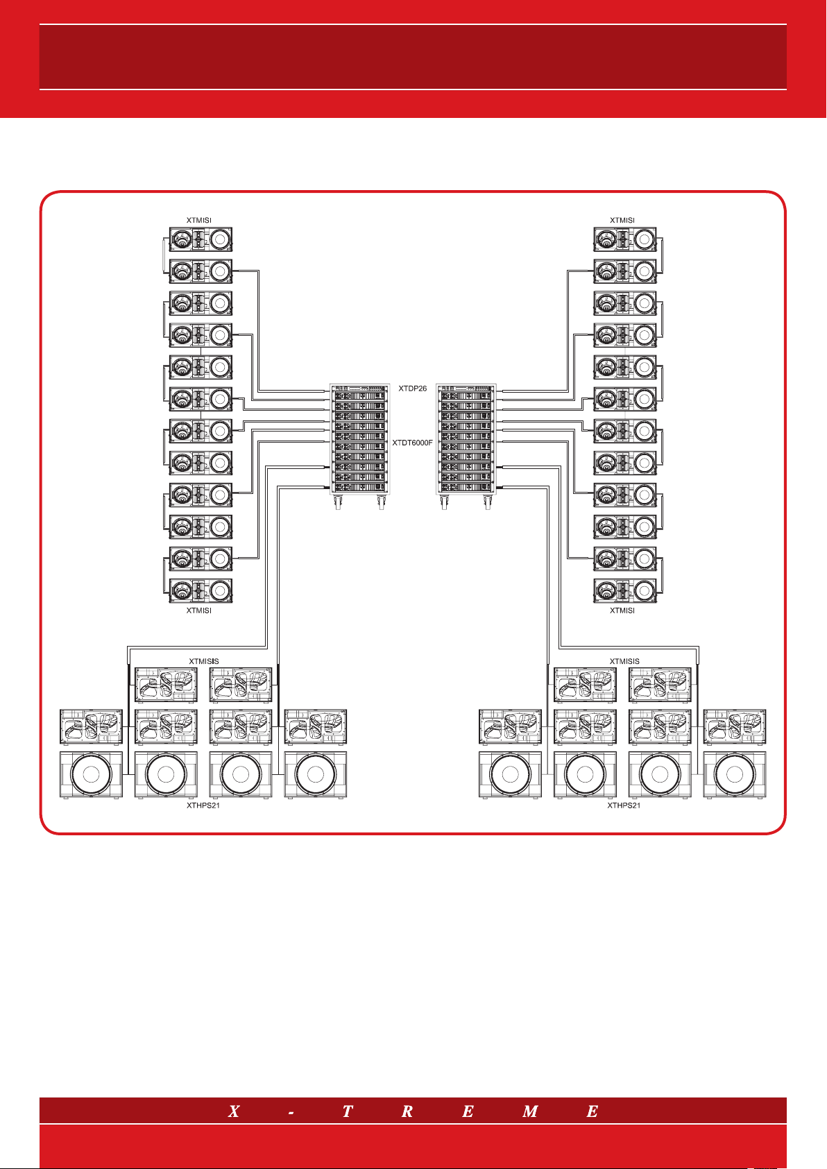
15. Tri-amplification system configuration
APPLICATIONS
• Large scale touring;
• Large open spaces, squares, etc…
• Stadiums, sports venues, large arenas;
• Huge fixed installations.
13/21
BRIEF DESCRIPTION
• Total Power Handling: 51600 W RMS
• Total Power Amplifiers:
• Horizontal coverage angle: 2 x 120°
• Reachable distance: 80-100 m
• Max potential audience: 20÷25000 people
120000
W RMS (@4 Ohm)
Page 14
UNITS
User’s manual
24 XTMISI
12 XTMISIS
8 XTHPS21
20 XTDT6000F
2 XTDP26
Middle-Sized Line Array module - Power handling RMS: 900 W - Impedance (bi-amp) 8+8 Ohm - Max SPL: 136 dB
Arrayable double subwoofer - Power handling RMS: 2400 W - Impedance: 4+4 Ohm - Max SPL: 140 dB
“Big Punch” Infra-bass subwoofer - Power handling RMS: 1500 W - Impedance: 8 Ohm - Max SPL: 139 dB
Stereo Switching Class D Amplifier with PFC (95-265 VAC) - Output Power RMS: 4x1500 W (@4 Ohm)
Digital Speaker Management System - Ways: 2 Input, 6 Output - Frequency response: 12÷20k Hz ±0.5 dB
CONNECTORS
The XTMISI and XTMISIS cabinets are fitted with a pair of Neu-
trik Speakon NL8 connectors, while XTHPS21 sub uses Neutrik
Speakon NL4. The double Speakon connector permits to connect
in parallel a fur ther loudspeaker system of the same type. All eight
Type
NL8
NL8
Pins
1+ 1- 2+ 2- 3+ 3- 4+ 4-
LF+
(XTMISI)
SW+
(XTMISIS)
SW-
(XTMISIS)
pins of both connectors are wired in parallel. The XTMISI uses the
pin assignments 2+/2- for woofer, 3+/3- for mid-high section in
bi-amp (this configuration) and 4+/4- for high section in tri-amp.
Pins 1+/1- are designed to XTMISIS and XTHPS21 subwoofers.
LF-
(XTMISI)
Mid/Hi+
(XTMISI
bi-amp)
Mid/Hi(XTMISI
bi-amp)
High+
(XTMISI
tri-amp)
High(XTMISI
tri-amp)
NL4
SW+
(XTHPS21)
SW-
(XTHPS21)
= Utilize d louds peaker s ystems- power amplifier s conne ctions .
PROCESSOR PROGRAMS
DSP UNIT SOUND FILE
XTDP26
12_XTMISI+XTMISIS+XTHPS21_Mono.dfa ---
(*) The “Far” output has a boost in the ultra- high freque ncy zone; to be us ed for a set of upper modules whi ch are position ed in the top part of th e array (suspended or stacked), depe nding on installation
geome try and e nviron menta l condit ions (arc hitecture, humidity), to thr ow the ver y high fr equen cies far enough, despite air abso rption.
12_XTMISI_Mono.dfa Near/Far*
OUTPUT
OPTIONS
FUNCTION
Array made of 12 bi-amplified elements
without subwoofer
Array made of 12 bi-amplified elements
with subwoofer
ACCESSORIES
STD-MISI
XT-ANGLE
XT-ANGLERC Remote controller for XT-ANGLE with bright display (cable included, 10 m in length)
XT-D8P Connection panel specially designed for line arrays
XT-PSB32/8 Patch board 32A - 2 XLR IN, 2 XLR OUT - 4 Speakon OUT NL8MPR - 3 rack units
XT-NETINT Network Interface for XT-NET connection (PC adapter: from USB or RS232 to standard RJ45)
XT-NETPS Power unit for supplying up to 2 XT-NETINT (if a RS232 is used)
XTMISIS-SK Wheelboard for XTMISIS and XTMISIS/A double subwoofer
XTHPS21-SK Wheelboard for XTHPS21 infra-bass subwoofer
Flying bar for Middle-Sized Line Array
Electro-mechanical device for setting the pitch of the line array systems (flying bar not included)
14/21
Page 15

LINE ARRAYS
16. System configurations: standard examples
16.1 Linear Source Array: DSP active solution
APPLICATIONS BRIEF DESCRIPTION
• Large scale concert & touring;
• Large open-air events, public squares, etc...
• Stadium, sports halls, arenas;
• Large fixed installations.
15/21
• Total Power Amplifiers: 22800 W RMS (@4 Ohm)
• Horizontal coverage angle: 2 x 120°
• Reachable distance: 70-80 m
• Max potential audience: 8000 people
Page 16

UNITS
User’s manual
8 XTLSA/A
4 XTLSAS/A
Active bi-amplified line array module - Amp. Power: 800+800 W RMS - Digital DSP on board (2 preset)
Active arrayable double subwoofer - Amp. Power: 2500 W RMS (@ 4 Ohm) - Digital DSP on board (2 preset)
CONNECTORS
The input signal for XTLSA/A and XTLSAS/A uses a female XLR
Bal connector. To wire the connector, use pin 2 for Hot (+), pin 3 for
Cold (-) and pin 1 for ground (GND).
Two internal presets are selectable through a switch positioned
in the rear side of the speakers. Moreover, thanks to the powerful DSP on board, it is possible to generate a cascade network of
Type
XLR
Pins
1 2 3
Ground
GND
Positive
(+)
Negative
(-)
N loudspeaker systems (XT-NET) via UTP CAT5 cable with RJ45
connectors – this allows the user to edit the audio parameters of
the speakers and hence to read the history of the amplifier status
from a single external PC.
A second XLR male connector permits the signal to be linked to
other additional loudspeaker systems.
PRESETS
DSP UNIT SOUND FILE
4_XTLSA_A_NoSub.dfa A (Near) / B (Far)*
XTLSA/A
4_XTLSA_A_Sub.dfa A (Near) / B (Far)*
XTLSAS/A XTLSAS_A.dfa
(*) Sele ctabl e via hard ware on the l oudsp eaker system’s rear pan el. The “Fa r” optio n (switch po sition: B) h as a boost i n the ultra -high fr equen cy zone; to be us ed for a set of upper mod ules wh ich are
positi oned in the top par t of the array (susp ended or stacked), dep ending on installa tion geom etry and en vironm ental con ditions (architecture, humi dity), to throw the ver y high frequencies far enou gh,
despi te air absorption. The sam e purpose can be ac compl ished w ith a manu al boos t in the 10 kHz zone.
(**) To use onl y with othe r upper module s - apar t from X TLSA - in ca se they hav e inver ted polarity re sponse .
HARDWARE
SWITCH OPTIONS
A (Polarity: normal) /
B (Polarity: inverted)**
FUNCTION
Array made of 4 active elements
without subwoofer
Array made of 4 active elements
with subwoofer
Subwoofer mode
ACCESSORIES
STD-LSA
XT-ANGLE
XT-ANGLERC Remote controller for XT-ANGLE with bright display (cable included, 10 m in length)
XT-NETINT Network Interface for XT-NET connection (PC adapter: from USB or RS232 to standard RJ45)
XT-NETPS Power unit for supplying up to 2 XT-NETINT (if a RS232 is used)
XTLSA-SK Wheelboard for XTLSA and XTLSA/A loudspeaker system
XTLSAS-SK Wheelboard for XTLSAS and XTLSAS/A double subwoofer
Flying bar for Linear Source Array
Electro-mechanical device for setting the pitch of the line array systems (flying bar not included)
16/21
Page 17

LINE ARRAYS
16.2 MISITM: passive solution powered by switching technology
APPLICATIONS BRIEF DESCRIPTION
• Medium/large scale touring;
• Central clusters, front fill, side fill, delay towers, etc...
• Medium/large open-air events, squares, etc…
• Stadiums, sports halls, arenas;
• Theme parks, circus shows;
• Theatres, auditoriums, music halls;
• Medium/large fixed installations;
• Large live clubs, music pubs and other live performance venues.
17/21
• Total Power Handling: 16800 W RMS
• Total Power Amplifiers: 15600 W RMS (@4 Ohm)
• Horizontal coverage angle: 2 x 120°
• Reachable distance: 60-70 m
• Max potential audience: 6000 people
Page 18

UNITS
User’s manual
8 XTMISI
4 XTMISIS
2 XTDT4800F
1 XTDT6000F
1 XTDP26
Middle-Sized Line Array module - Power handling RMS: 900 W - Impedance (bi-amp) 8+8 Ohm - Max SPL: 136 dB
Arrayable double subwoofer - Power handling RMS: 2400 W - Impedance: 4 Ohm - Max SPL: 140 dB
Stereo Switching Class D Amplifier with PFC (95-265 VAC) - Output Power RMS: 4x1200 W (@4 Ohm)
Stereo Switching Class D Amplifier with PFC (95-265 VAC) - Output Power RMS: 4x1500 W (@4 Ohm)
Digital Speaker Management System - Ways: 2 Input, 6 Output - Frequency response: 12÷20k Hz ±0.5 dB
CONNECTORS
The XTMISI and XTMISIS cabinets are fitted with a pair of Neutrik
Speakon NL8 connectors. The double Speakon connector per-
mits the parallel connecton of a further loudspeaker system of the
same type. All eight pins of both connectors are wired in parallel.
Type
NL8
NL8
Pins
1+ 1- 2+ 2- 3+ 3- 4+ 4-
LF+
(XTMISI)
SW+
(XTMISIS)
SW-
(XTMISIS)
The XTMISI uses pin assignments 2+/2- for woofer, 3+/3- for
mid-high section in bi-amp (this configuration) and 4+/4- for
high section in tri-amp. Pins 1+/1- are designed for XTMISIS
subwoofers.
LF-
(XTMISI)
Mid/Hi+
(XTMISI
bi-amp)
Mid/Hi(XTMISI
bi-amp)
High+
(XTMISI
tri-amp)
High(XTMISI
tri-amp)
= Utilize d louds peaker s ystems- power amplifier s conne ctions .
PROCESSOR PROGRAMS
DSP UNIT SOUND FILE
XTDP26
(*) The “Far” output has a boost in the ultra- high freque ncy zone; to be us ed for a set of upper modules whi ch are position ed in the top part of th e array (suspended or stacked), depe nding on installation
geome try and e nviron menta l condit ions (arc hitecture, humidity), to thr ow the ver y high fr equen cies far enough, despite air abso rption.
4_XTMISI_BiAmp_Stereo.dfa Near/Far*
4_XTMISI_BiAmp+XTMISIS_Stereo.dfa ---
OUTPUT
OPTIONS
FUNCTION
Array made of 4 bi-amplified elements
without subwoofer
Array made of 4 bi-amplified elements
with subwoofer
ACCESSORIES
STD-MISI
XT-ANGLE
XT-ANGLERC Remote controller for XT-ANGLE with bright display (cable included, 10 m in length)
XT-D8P Connection panel specially designed for line arrays
XT-PSB32/8 Patch board 32A - 2 XLR IN, 2 XLR OUT - 4 Speakon OUT NL8MPR - 3 rack units
XT-NETINT Network Interface for XT-NET connection (PC adapter: from USB or RS232 to standard RJ45)
XT-NETPS Power unit for supplying up to 2 XT-NETINT (if a RS232 is used)
XTMISIS-SK Wheelboard for XTMISIS and XTMISIS/A double subwoofer
Flying bar for Middle-Sized Line Array
Electro-mechanical device for setting the pitch of the line array systems (flying bar not included)
18/21
Page 19

LINE ARRAYS
16.3 Mini Line Array: passive solution with “Big punch” powered by switching technology
APPLICATIONS BRIEF DESCRIPTION
• Medium/small scale concert & touring;
• Central clusters, front fill, side fill, delay towers, etc...
• Medium/small open-air events, public squares, etc…
• Theme parks, circus shows;
• Theatre sound reinforcement;
• Houses of worship;
• Medium fixed installations;
• Medium/large live clubs, music pubs and others;
• Multi-purpose venues and congress/fairs centres;
• Corporate A/V events;
• Small to medium sized portable PA systems.
19/21
• Total Power Handling: 13600 W RMS
• Total Power Amplifiers: 18400 W RMS (@4 Ohm)
• Horizontal coverage angle: 2 x 120°
• Reachable distance: 50-60 m
• Max potential audience: 4000 people
Page 20

UNITS
User’s manual
8 XTMLA
4 XTHPS36
2 XTDT3200
2 XTDT6000F
1 XTDP26
Mini Line Array module - Power handling RMS: 500 W - Impedance (bi-amp) 16+16 Ohm - Max SPL: 133 dB
“Big Punch” Double Subwoofer - Power handling RMS: 2400 W - Impedance: 4+4 Ohm - Max SPL: 143 dB
Stereo Switching Class D Amplifier with PFC (95-265 VAC) - Output Power RMS: 2x1600 W (@4 Ohm)
Stereo Switching Class D Amplifier with PFC (95-265 VAC) - Output Power RMS: 4x1500 W (@4 Ohm)
Digital Speaker Management System - Ways: 2 Input, 6 Output - Frequency response: 12÷20k Hz ±0.5 dB
CONNECTORS
The XTMLA cabinets are fitted with a pair of Neutrik Speakon NL8
connectors. All eight pins of both connectors are wired in parallel.
The XTMLA uses the pin assignments 2+/2- for woofer, 3+/3- for
mid-hi section in bi-amp (this configuration) and 4+/4- for high
Type
NL8
NL4
Pins
1+ 1- 2+ 2- 3+ 3- 4+ 4-
LF+
(XTMLA)
Woofer 1+
(XTHPS36)
Woofer 1-
(XTHPS36)
Woofer 2+
(XTHPS36)
section in tri-amp. The XTHPS36 uses a pair of NL4 Neutrik Spe-
akon. Pins 1+/1- are assigned to XTHPS36 woofer 1 and 2+/2- to
woofer 2. The double Speakon connector permits parallel con-
nection of a further loudspeaker system of the same type.
LF-
(XTMLA)
Woofer 2-
(XTHPS36)
Mid/Hi+
(XTMLA
bi-amp)
Mid/Hi-
(XTMLA
bi-amp)
High+
(XTMLA
tri-amp)
High(XTMLA
tri-amp)
= Utilize d louds peaker s ystems- power amplifier s conne ctions .
PROCESSOR PROGRAMS
DSP UNIT SOUND FILE
XTDP26
(*) The “Far” output has a boost in the ultra- high freque ncy zone; to be us ed for a set of upper modules whi ch are position ed in the top part of th e array (suspended or stacked), depe nding on installation
geome try and e nviron menta l condit ions (arc hitecture, humidity), to thr ow the ver y high fr equen cies far enough, despite air abso rption.
4_XTMLA_BiAmp_Stereo.dfa Near/Far*
4_XTMLA_BiAmp+XTHPS36_Stereo.dfa ---
OUTPUT
OPTIONS
FUNCTION
Array made of 4 bi-amplified elements
without subwoofer
Array made of 4 bi-amplified elements
with “Big punch” subwoofer
References
H. F. Olson, “Elements of acoustical engineering”, Van Nostrand, New York (1940)
D. L. Klepper, D. W. Steele, “Constant directional characteristics from a line source array”, AES (Audio Engineering Society), vol.11, no.3 (1963)
L. L. Beranek, “Acoustics”, AIP (American Institute of Physics), 3rd printing (1990)
C. Heil, “Sound fields radiated by multiple sound source arrays”, J. Audio Eng. Soc., vol.40 (1992)
M. S. Ureda, “Analysis of loudspeaker line arrays”, J. Audio Eng. Soc., vol.52, no.5 (2004)
20/21
Page 21

Contacts
www.x-tremeaudio.com
X-Treme Headquarters:
via Monti Urali, 33 - 42100 Reggio Emilia - Italy
tel. +39 0522 557735
fax +39 0522 391268
X-Treme Audio reserves the rights to change or modify products and specifications at any time without prior notice.
X-Treme and the corresponding symbols, images and registered trademarks are of exclusive property of Sound Corporation group. © 2010 Sound Corporation group. All rights reserved.
21/21
For technical support/information: support@x-tremeaudio.com
For general information: info@x-tremeaudio.com
For commercial information: sales@x-tremeaudio.com
 Loading...