

Page 1
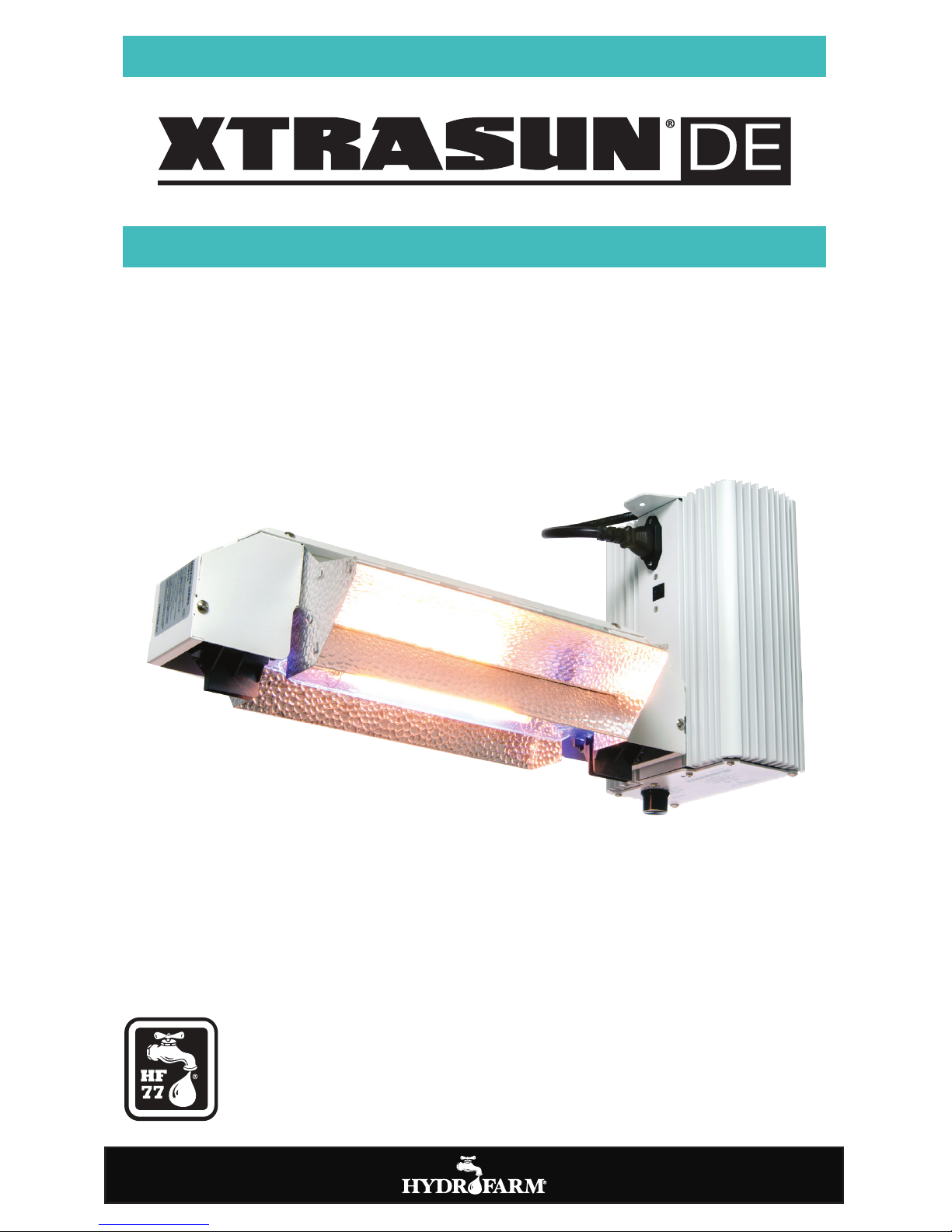
USER MANUAL
XTDEOKT1
COMPLETE LIGHTING SYSTEM OPEN SYSTEM
Page 2
TOOLS NEEDED - (FOR HANGING)
Adjustable
WRENCH
LEVEL LADDER
OVERVIEW
Thank you for purchasing the XTRASUN DE Double-Ended 1000W Open Lighting System. This
system is engineered to provide ultra-wide, uniform, efficient light delivery over the growing area.
For information on additional Xtrasun products please visit Hydrofarm.com.
WARNING: FAILURE TO FOLLOW OUR GUIDELINES COULD RESULT IN ELECTRICAL SHOCK.
Do not touch, move, spray, or clean your light fixture when it is plugged in. Allow it to cool down be
-
fore handling. Recommended mounting clearance for your fixture is 8”-12” on all sides. Do not mount
directly to any surface. Make sure to disconnect the power when changing the lamp.
XTRASUN DE SERIES BALLAST ELECTRICAL SPECIFICATIONS
Model Watts
Main
Voltage
Operating
Voltage
Range
Max
Input
Power
Output Power Settings
Power
Factor
Ignitor
Voltage
THD CF ta tc
XTDE1TH
1000W 240V 216-264V 1200W 600W-750W-825W-1000W-1150W > 0.99 4 kV <10% <1.7 40°C/104°F 75°C/167°F
Model
BALLAST INPUT AMPERAGE REFERENCE
XTDE1TH
Imax 240V 1150W 240V 1000W 240V 825W 240V 750W 240V 600W 240V
5.06A 5.06A 4.60A 3.91A 3.48A 2.86A
2
Page 3
PARTS LIST - (WHAT’S IN THE BOX)
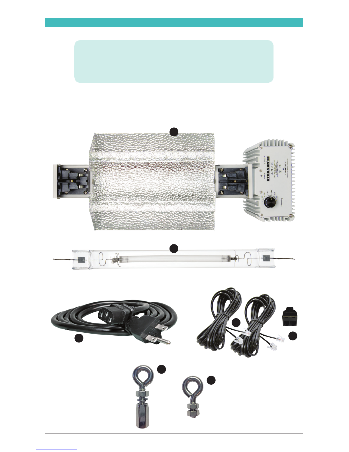
PARTS LIST
A
- Complete Open System
B - DE Lamp
C - Power Cord
D - RJ14 Cables (x2)
E - RJ Splitter
F - Rear Hanging Eye-Hook
G - Spare Hanging Eye-Hook
A
B
C
D
E
F
G
3
Page 4
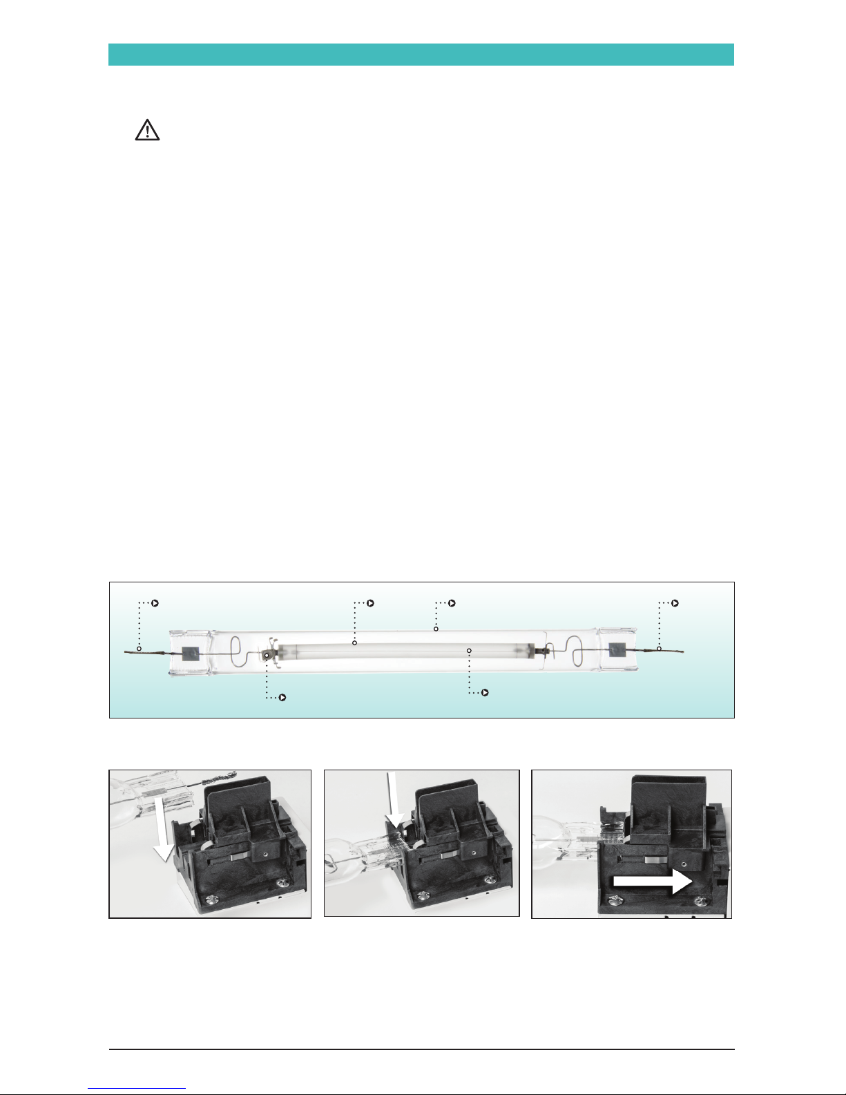
1. Open both lamp holders by sliding them outwards and away from the center of the fixture, as
shown in PHOTO C.
Do not apply excessive force when installing lamp.
NOTE: The bulb must be oriented so that the high voltage wire end/lead (the end near the getter,
which is the small square tab attached to the wire loop) is installed in the socket end closest to the
ballast as seen in DIAGRAM A.
2. Also be sure that the bulb is oriented so that the burner filament (the long wire that runs
along the full length of the arc tube) is positioned upward, facing the top inside surface of the
reflector.
3. Ensure that the wire ends/leads are not bent or frayed, as this will prevent proper installation.
Begin by installing the double-ended lamp within the lamp holders shown in PHOTOS A, B & C.
4. The wire ends/leads must be fully seated as shown (PHOTOS D & E) before sliding each socket
end closed.
5. After sliding the socket ends closed, be certain that there is no gap between the edge of the
sliding section and the part it meets at the end of the slide path. Once lamp is positioned
correctly, slide the lamp holder inward toward the center of the bulb to secure and lock the
lamp in place as shown in PHOTOS F & G.
PLEASE NOTE: Do not force the lamp holders closed. This could cause damage to both the lamp and
lamp holders. Do not handle lamp with bare hands. Always wear surgical or cloth gloves whenever
possible when handling lamp to minimize fingerprints and oils left on the lamp. If the lamp needs
cleaning after installation, use a soft dry cotton cloth to wipe off fingerprints/skin oils.
PHOTO A
PHOTO C
PHOTO B
Anode
(Closest to Ballast)
Getter
(absorbs lamp impurities)
Burner Filament
(always position up)
CathodeArc Tube Quartz Outer Jacket
DIAGRAM A
LAMP INSTALLATION
4
Page 5
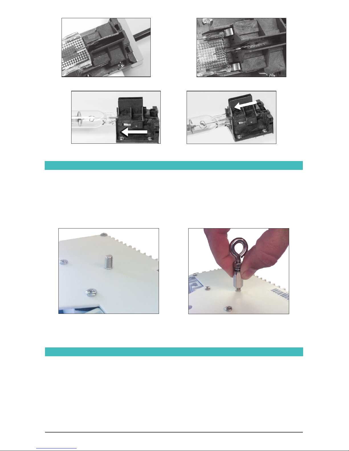
PHOTO F PHOTO G
PHOTO E
PHOTO D
HANGING YOUR FIXTURE
• The lamp may require 10-30 minutes cooling time before restarting.
• After you plug the reflector in, the bulb may require several minutes to reach its full brightness. In the
event of a momentary power interruption, the bulb will not restart immediately.
• Some variation in the color of light emitted by the bulb is not unusual, especially in the first 100
hours of operation.
• Never pull the cord to unplug the reflector, pull the plug only.
• Avoid scratching the bulb, subjecting it to undue pressure, or getting it wet when it is hot; these
actions may cause the bulb to break.
TIPS
1. Make sure your unit is unplugged.
2. Install rear hanging eye hook to threaded stud on top of the ballast. Tighten with adjustable
wrench. (see images below)
3. Hang the fixture from a strong cord or chain from both ends. Make sure you have hooks solidly
screwed into the studs in the ceiling. If you cannot locate the studs, insert expansion anchors
into the ceiling. The hooks should be rated to hold at least 50 lbs each.
5
Page 6
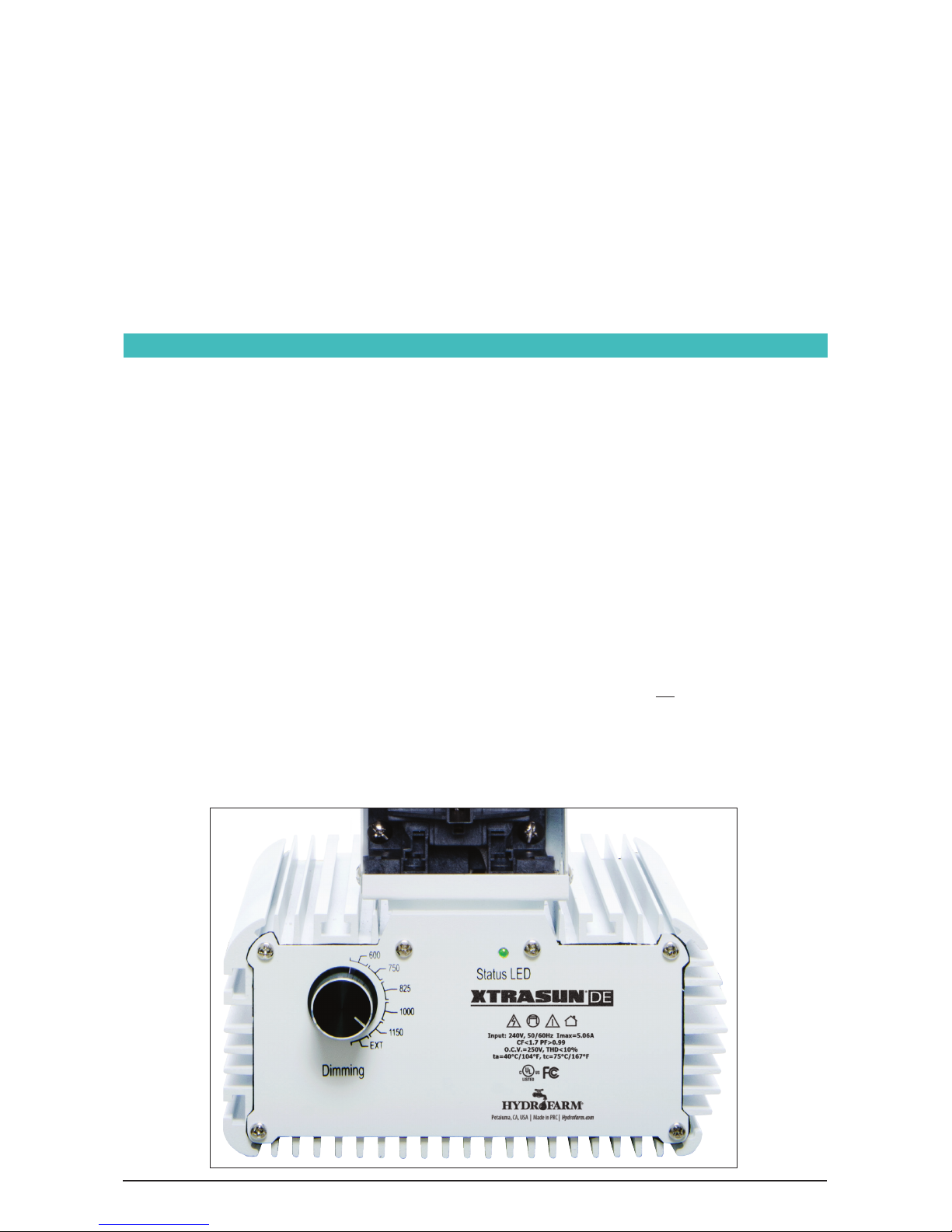
The multi-color status LED provides information on the status of the ballast with respect to its
connection to a controller and its general operating condition, and also gives error and warning
signals. Consult the tables at right to interpret the status LED.
• All operating codes are represented by GREEN signals.
• All warning codes are represented by RED signals.
• All history codes (except the ignition code) are represented by YELLOW signals.
• BLACK dots in the diagrams represent the unlit LED.
• Warning codes and history codes override operating mode display.
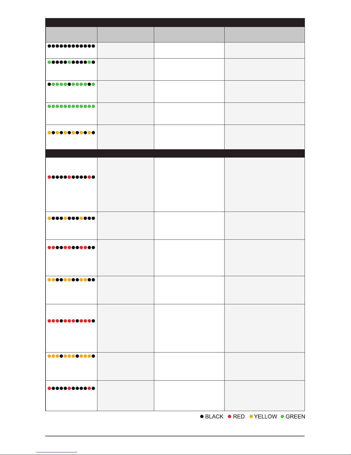
LED signals are represented by colored dots in the diagrams in the table. In the STATUS INDICATIONS
table, the green dots do not represent individual flashes; instead they represent the duration that
the LED is illuminated green. Each dot shown in both diagrams represents one half second. For
example, the “Ballast on” signal is shown as a black dot and then four green dots. This indicates a
dark (unlit) LED for one half second and then a long green flash lasting two seconds.
In the ERROR OR WARNINGS INDICATIONS table, the individual colored dots do represent individual
flashes (black dots represent time that the LED is unlit between flashes). They also represent the
relative time duration of signals (each dot still represents one half second). For example, the “Too
high voltage” signal is shown as two red dots followed by two black dots. This indicates two red
flashes of one half second each followed by one second of a dark (unlit) LED.
TROUBLESHOOTING USING THE BALLAST’S STATUS LED
• In the event of bulb breakage, immediately unplug the reflector to prevent exposure to ultraviolet
energy, which may be harmful to eyes and skin.
• Keep room temperature below 95°F, with adequate air circulation by fan in the growing area.
• The DE lamp produces very high-intensity light and was originally designed for commercial
growing operations. Please take care to consider proximity to plants when installing your fixture.
You may want to allow more vertical space between the plant canopy and the fixture to mitigate the
high-intensity light and heat in the plant area.
• Always use a heavy-duty 3-pronged grounded timer, rated for at least 15 amps. Many 7-day digital
timers are not rated for 1000W lamps. Unplug ballast when changing or removing the lamp. Failure
to do so can cause ballast failure or improper diagnosis.
6
Page 7
STATUS INDICATIONS
LED Status
Message
Fixture Status Description Action/Solution
No LED activity
No power/off
The fixture is not connected to
the mains or the power is off
Check power
Short green flash with
long off interval
Ballast stand-by (on EXT)
Fixture is connected to the mains
and to a controller. Output of
ballast is off
No action required
Long green flash with
brief off interval
Ballast on (on EXT)
Fixture is connected to the mains
and to a controller. Output of
ballast is on
No action required
Solid green on with no
off interval
Ballast on (Manual dim)
Fixture is connected to the mains
and set to manual output
No action required
Rapid yellow flash
Fixture is igniting the lamp
Fixture is trying to restart the
lamp
When lamp does not start: Lamp may
be too hot, defective or not properly
connected (remote). Disconnect,
check power cord and connections
ERROR OR WARNING INDICATIONS
One rapid red flash with
long off interval
Too low voltage
Input voltage is too low
Ballast power drops to 50%
automatically
If used it with 120V input power
accidently, the ballast power will
decrease to 50% of the set power
automatically. Turn off the ballast and
replace it with correct 240V input
power. If the voltage is a bit lower
than 240V, the LED will blink and
the ballast keeps running with set
wattage.
One rapid yellow flash
with long off interval
Too low voltage occurred
in past
Input voltage was too low in
the past
Ballast power drops to 50%
automatically
See above, reset
Two rapid red flashes
with medium-long off
interval
Too high voltage
Input voltage is too high
Ballast power drops to 50%
automatically
Disconnect the ballast. Check input
voltage, check wiring and connection,
check neutral in 3 phase systems,
then reconnect the ballast. LED on
the ballast will blink but power will
not change.
Two rapid yellow
flashes with medium-
long off interval
Too high voltage occurred
in past
Input voltage was too high in
the past
Ballast power drops to 50%
automatically
See above, reset
Three rapid red flashes
with brief off interval
Too high temperature
Electronics temperature is too
high (max. 115°C/239°F)
There is temperature sensor in the
PCB of the ballast. If it senses the
internal ballast temperature reaches
110C, the LED will start to blink. The
ballast power will decrease to 50%
of the set power automatically. Users
should turn off the ballast or cool
down the ballast.
Three rapid yellow
flashes with brief off
interval
Too high temperature
occurred in past
Electronics temperature was
too high in the past (max.
115°C/239°F)
See above, reset
One rapid red flash with
prolonged off interval
No signal from controller
(on EXT)
Fixture is connected to the mains
and set to EXT but there is no
signal on the control input.
If a controller is connected, search
for loose connections, defective
contacts or short-circuits. Re-connect
the controller to the ballast or verify
whether the controller is out of order..
7
Page 8
Hydrofarm.com
WARRANTY
XTDEOKT1 Instructions revised - August 31, 2017 2:04 PM
Thank you for choosing Xtrasun by Hydrofarm. For further information
about Xtrasun products, videos, and technical information,
please visit hydrofarm.com
LIMITED WARRANTY
Hydrofarm warrants the XTDEOKT1to be free from defects in materials and workmanship. The warranty term is for
1 year beginning on the date of purchase. Misuse, abuse, or failure to follow instructions is not covered under this
warranty. Hydrofarm’s warranty liability extends only to the replacement cost of the product. Hydrofarm will not be
liable for any consequential, indirect, or incidental damages of any kind, including lost revenues, lost profits, or other
losses in connection with the product. Some states do not allow limitation on how long an implied warranty lasts or
the exclusion of incidental or consequential damages, so the above limitations or exclusions may not apply to you.
Hydrofarm will, at our discretion, repair or replace the XTDEOKT1 covered under this warranty if it is returned to the
original place of purchase. To request warranty service, please return the XTDEOKT1, with original sales receipt and
original packaging, to your place of purchase. The purchase date is based on your original sales receipt.
Like us on Facebook, follow us on Twitter,
and check out Hydrofarmtv on YouTube and Instagram!
Get Connected with the Hydrofarm Community:
 Loading...