

Page 1
These installation instructions provide essential information for installing VESDA-E VEU Aspirating Smoke Detectors in accordance with the system design. Additional installation and
product documentation is listed below in the Reference Documents section.
VESDA-E VEU Installation Instructions
System Components
The detector is shipped with the following components:
• 1 aspirating smoke detector
• 1 mounting bracket
• 1 mounting template for directly mounting the detector to the mounting surface
• 1 End of Line Resistor for the monitored GPI
• 1 installation instruction sheet
Prerequisites
• A completed system design.
• A 24V DC Power Supply, compliant with local codes and standards.
• Screws and inserts that are appropriate for the mounting suface.
• Type A to Type B USB Interface Lead for initial conguration of the detector.
• Labels as specied in the system design, e.g. Sampling Point labels
• Cable glands that are compliant with the IP rating of the detector.
• Conduit, as specied in the system design.
• 0.2 mm2 to 2.5 mm2 (24 - 14 AWG) wiring for relays.
• A PC or laptop installed with Xtralis VSC for initial conguration.
• Standard connection instructions for where the detectors are to be added to a corporate
network.
Standards Compliance
UL and ULC
For open area, open area high velocity and duct protection the re alarm threshold (setting)
that initiates an evacuation signal must be set such that the sensitivity of each sampling
hole is more sensitive than 10%/m (3.2 %/ft) as determined by the ASPIRE software.
European Installations
The product must use a power supply conforming to EN54: Part 4.
The product is compliant with EN 54-20 sensitivity requirements provided the following
conditions are met:
• For a Class A detector, hole sensitivity must be better than 1.5% obscuration/m and
transport time less than 70 seconds
• For a Class B detector, hole sensitivity must be better than 3% obscuration/m and
transport time less than 90 seconds
• For a Class C detector, hole sensitivity must be better than 10% obscuration/m and
transport time less than 110 seconds
These limits should be veried using ASPIRE during the design of the sampling pipe
network.
The product is compliant with EN 54-20 ow monitoring requirements provided the
following conditions are met:
• The minor low and minor high ow thresholds should be set at 85% and 115%
respectively
• The ow through the detector predicted by ASPIRE must be greater than 20 L/m.
Power Consumption (18 - 30 VDC Supply)
Quiescent In Alarm
Aspirator Speed Setting 1 Setting 5 Setting 10 Setting 1 Setting 5 Setting 10
VEU-A00 7.0 W 8.8 W 14.7 W 7.8 W 9.6 W 15.5 W
VEU-A10 8.2 W 10.0 W 15.8 W 10.4 W 11.6 W 16.6 W
Environmental Requirements
• Temperature
• Ambient: 0°C to 39°C (32°F to 102°F)
• Sampled Air: -20°C to 60°C (-4°F to 140°F)
• Tested to: -20°C to 55°C (-4°F to 131°F)
UL: -20°C to 50°C (-4°F to 122°F)
• Humidity: 10-95% RH, non-condensing
Note:
Please consult your Xtralis representative for information on operation outside
these parameters or where sampled air is continually above 0.05% obs/m
(0.015% obs/ft) under normal operating conditions.
Reference Documents
Additional installation and product information is contained in the following documents,
which are available for download in the Xtralis partner extranet at www.xtralis.com.
• 22061 - VESDA-E VEU-A00 Product Guide
• 22077 - VESDA-E VEU-A10 Product Guide
Installation Instructions
Notes
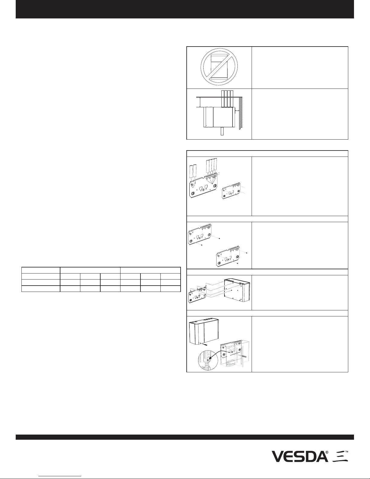
The VESDA-E detector can be mounted in an
upright or inverted position. Do not mount the
detector with a sideways orientation.
Ensure the mounting surface is at as this allows an
air tight seal to be achieved between the sampling
pipe and the tapered air inlet pipes on the detector.
Refer to the detector Product Guide for information
on inverted mounting.
A
B
Ensure that there is sufcient clearance to mount
the detector, noting the location of air sampling
pipes and cable entry points. Due to the rigid nature
of the plastic pipe, installation must provide for
sufcient movement in all pipework (air inlet, air
exhaust and cable pipes) to allow pipe ends to be
easily tted and removed.
• A: Minimum 50 mm (2 in.) below ceiling level.
• B: The detector can be mounted directly
against a wall or obstruction.
Attach the detector to the wall using the mounting bracket
Position the mounting bracket as specied by the system designer
E
F
B
D
A
C
D
G
G
G
G
G
• Position the mounting bracket (A) to allow sampling
pipes (B) and electrical conduit (C) to line up
horizontally with the alignment marks (D) and
vertically with the appropriate pipe depth line.
• 3/4 inch IPS (1.05 inch OD) sampling pipe should
vertically align with the top depth line (E).
• 25 mm OD sampling pipe should vertically
align with the bottom depth line (F).
• Hold the plate in position and mark positions
for 5 screw holes (G) on the mounting surface.
Remove the plate and drill holes. Insert plugs if
required.
Secure the mounting bracket to the mounting surface
B
B
D
D
A
D
C
C
• Align the mounting plate with the holes. Ensure
that the plate is level.
• Insert and tighten two screws (B) in the keyhole
slots (C) followed by three screws (D) in the
remaining slots.
• Use screws and inserts that are appropriate
for the mounting surface and the weight of the
detector.
Position the detector on the mounting bracket
A
A
A
B
C
• Align the mounting studs (A) on the rear of the
detector with the mounting stud slots on the
mounting bracket. Ensure that the center stud
(B) is in its slot.
• Slide the detector (C) down until the top of the
detector is ush with the top of the mounting
bracket.
Secure the detector to the mounting bracket
A
B
C
C
• Open the door on the front of the detector by
inserting a thin screwdriver (A) into the hole at
bottom left of the door (B) and rmly pushing
perpendicular to the door surface to release the
door latch.
• Remove the tape covering the partially inserted
locking screw (C).
• Tighten the locking screw.
Attach the detector directly to the mounting surface
Use the provided mounting template. Refer to the Product Guide for further information.
Note:
Do not remove the mounting studs from the rear of the detector as they are also
used to hold internal components in place.
Inverted Mounting
Some system designs require that the detector be inverted. Directions for correcting the
orientation of the fascia for an inverted detector are available in the Product Guide.
Page 2
The contents of this document are provided on an “as is” basis. No representation or warranty (either express or implied) is made as to the completeness, accuracy or reliability of the contents of this document. The
manufacturer reserves the right to change designs or specications without obligation and without further notice. Except as otherwise provided, all warranties, express or implied, including without limitation any implied
warranties of merchantability and tness for a particular purpose are expressly excluded.
Xtralis, the Xtralis logo, The Sooner You Know, VESDA-E, VESDA, ICAM, ECO, OSID, HeiTel, ADPRO, IntrusionTrace, LoiterTrace, ClientTrace, SmokeTrace, XOa, XOh, iTrace, iCommand, iRespond, iCommission,
iPIR, and FMST are trademarks and/or registered trademarks of Xtralis and/or its subsidiaries in the United States and/or other countries. Other brand names mentioned herein are for identication purposes only and
may be trademarks of their respective holder(s). Your use of this document does not constitute or create a licence or any other right to use the name and/or trademark and/or label.
This document is subject to copyright owned by Xtralis. You agree not to copy, communicate to the public, adapt, distribute, transfer, sell, modify or publish any contents of this document without the express prior written
consent of Xtralis.
www.xtralis.com
UK and Europe +44 1442 242 330 D-A-CH +49 431 23284 1 The Americas +1 781 740 2223
Middle East +962 6 588 5622 Asia +86 21 5240 0077 Australia and New Zealand +61 3 9936 7000
Part: 30317
VESDA-E VEU Installation Instructions
Prepare Detector: Wiring, Pipe Inlet and Exhaust Ports
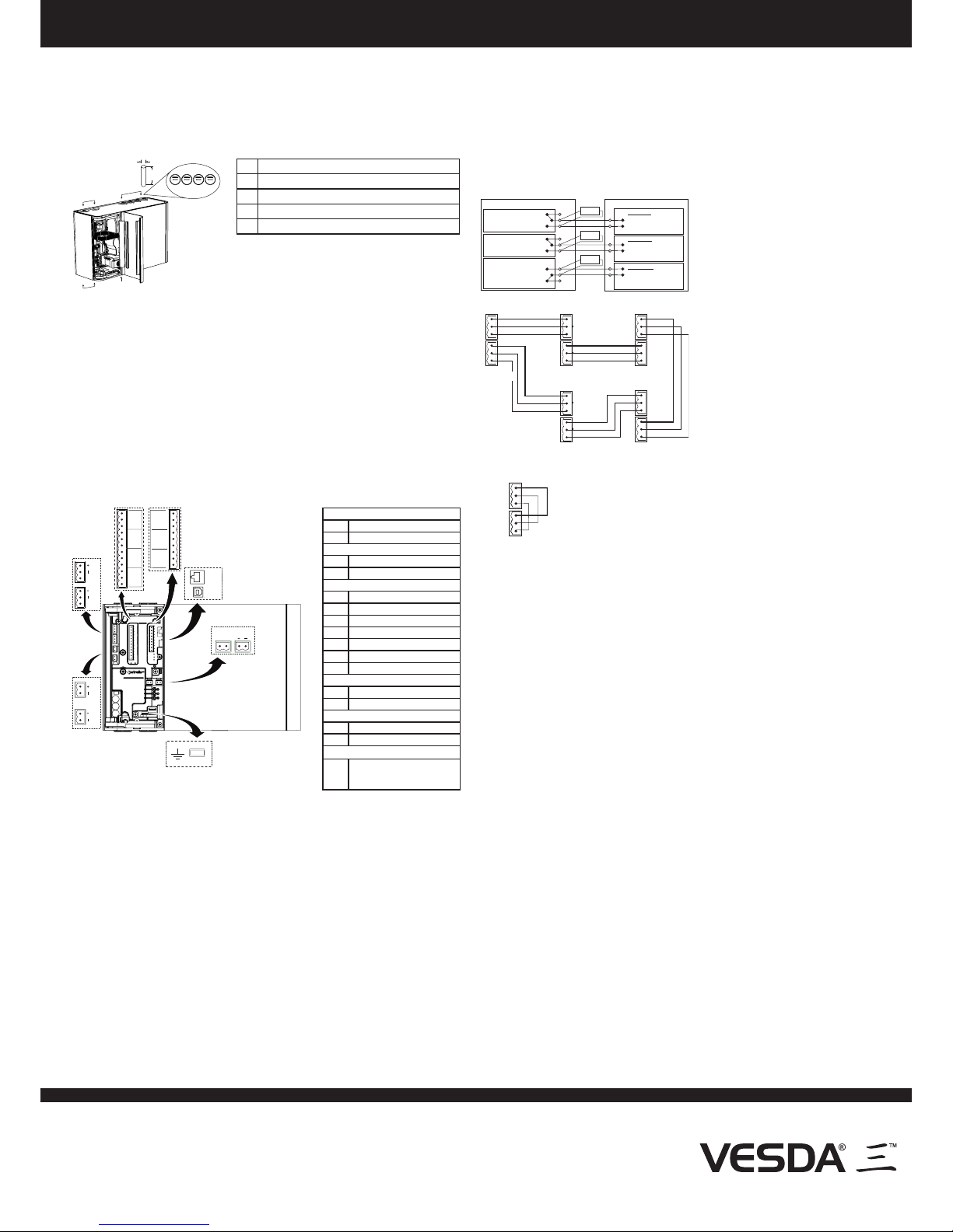
Remove the appropriate plugs for electrical cable installation (B), air sampling pipe inlet
ports (A), and exhaust port (C).
• Where the system design requries less than four air sampling pipe inlet ports, use
ports 2 and 3 before using ports 1 and 4.
• Do not remove the plugs from inlet ports that will not be used.
• Ensure that pipes are clean and their ends are square and smooth.
A
B
B
C
E
D
12
34
INLETS
A Inlet Port, Qty 4
B Cable Entry Port, Qty 4, 26 mm (1”)
C Exhaust Port, OD 25 mm or 1.05” (3/4” IPS) via adaptor
D Inlet Pipe Diameter: OD 25 mm or 1.05” (3/4” IPS)
E Minimum Inlet Pipe Length: 500mm (19.6”)
• Insert the inlet and exhaust pipes (if used) into the correct inlet ports (A) and
exhaust port.
• Exhaust pipe should be as short as possible.
• Feed the electrical wiring connections through the cable entry ports.
• Use the correct cable gland size to t into the 26 mm (1”) cable entry port. Use
correctly rated cable glands to maintain the required IP rating.
Note: Do not glue the inlet and exhaust pipe into the detector ports. The product
warranty will be void if the pipes are glued.
Wiring: Power, Relays, GPI, Loop Module, VESDAnet, Standalone Detector
Warning:
Always switch detector power OFF before plugging/unplugging electrical, relay
or network connections. Failure to do so may cause data corruption and/or
component failure.
Avertissement : Eteignez toujours détecteur avant de brancher/débrancher les relais électriques, ou de
connexions réseau. Au cas contraire vous pouver entraîner la défaillance corruption et/ou
élément de données.
SHSH
NC C NO
NC C NO NC C NO
2 [MINOR F]
NC C NO
1 [ISOL]
5 [ACTION]
NO C NC
6 - FIRE 1
NO C NC
7 [FIRE 2]
NO C NC
A
B
C
D
H
G
F
E
I
J
K
L
M
O
N
4 [ALERT]
3 - URGENT F
P
Power
A Power Out
B Power In
VESDAnet
C VESDAnet B
D VESDAnet A
Relays
E 1 - Isolate (Disable)
F 2 - Minor Fault
G 3 - Urgent Fault
H 4 - Alert
I 5 - Action
J 6 - Fire 1
K 7 - Fire 2
Communications
L USB
M Ethernet
GPI
N Monitored GPI
O Unmonitored GPI
GPI
P Ground Reference Terminal
For UL/ULC installations connect to local
ground to enable ground fault detection on
VESDAnet.
Power and Relay Wiring
Power: There are two sets of power terminals on the main board. Connect a 24 VDC
power supply to the PWR IN socket (B). If required, connect to another detector via the
PWR OUT socket (A).
Relays:
The relays interface to the Fire Alarm Control Panel (FACP) to communicate
faults, alarms and disabled states. Relay contacts are rated 2 A @ 30 VDC, resistive.
Connect as required by the system design. Use electrical wire sizes from 0.2 mm² to
2.5 mm² (24 -14 AWG). Refer to the Addressable Loop Module example.
Warning: Ensure that all wiring complies with manufacturer’s instructions and local and
national re detection code requirements. Refer to Codes and Standards
Information for Air Sampling Smoke Detection section of the detector product
guide for further information on wiring compliance.
Avertissement : Verier que toute les cables ont passé au nombres d’instructions du fabricant et locaux et au
feu national de securited’incendie sois exiger. Adresser aux codes informations sur les normes
et reglementations de detection de fume par prelevement d’air par le notice descriptive du
produit pour plus de renseignements au conformite du cablage.
Caution: DO NOT LOOP WIRE UNDER TERMINALS WHEN WIRING DETECTORS.
BREAK WIRE RUNS TO PROVIDE SYSTEM SUPERVISION OF CONNECTIVITY.
Attention : NE PAS RALIER LES CABLES TERMINAUX PENDANT LES CABLAGES DES FILS. POUR
TOUTES LES CONNECTIONS A RELAIS, INTERROMPRE LES FILS POUR PERMETTRE LA
SUPERVISION DU CABLAGE.
Note: For information on wiring for other types of devices that may be required by
the system design, refer to the detector Product Guide and documentation
accompanying the device.
Unmonitored GPI
The Unmonitored GPI is a programmable input which can be congured to initiate a
number of different actions, including, by default, a Remote Reset function.
Monitored GPI
The monitored GPI senses contact closure and is congurable to initiate the same actions
as the unmonitored GPI. “Mains OK” is the default setting. A closed contact signals GPI
ON and open contact signals GPI OFF.
A 10K end of line resistor is used to allow the detector to monitor for open circuit faults in
the wiring from the detector to the contact.
Connection to Addressable Loop Module for Reporting Alarms and Faults
Normally Closed (NC)
Common (C)FIRE 1
(NO)Normally Open
Normally Closed (NC)
Common (C)ACTION
(NO)Normally Open
Dete torc
Fire Input
EOL* = Normal
Short = Fire
Open = Wiring Fault
3 Inputs Loop Module
Pre Alarm
EOL* = Normal
Short = Fire
Open = Wiring Fault
EOL*
EOL*
Relay shown energized which
is the no-fault condition
Normally Closed (NC)
Common (C)FAULT
(NO)Normally Open
Fault Input
EOL* = Normal
Detector FaultShort =
Open = Wiring Fault
EOL*
This wiring example is for wiring VESDA
detectors to a typical third party Input Loop
Module with three inputs.
This is an example drawing. Refer to the
appropriate product manual for the exact
wiring details of the third party equipment.
* EOL = End of Line Resistor
Connection to VESDAnet
A+
A-
B-
Shield
Module 1
Module 2 Module 3
Module 5 Module 4
Shield
B+
A+
A-
B-
Shield
Shield
B+
A+
A-
B-
Shield
Shield
B+
A+
A-
B-
Shield
Shield
B+
A+
A-
B-
Shield
Shield
B+
(VESDA-E VEU)
The diagram shows an example of the
wiring for a closed VESDAnet loop, which
is the recommended conguration. Remove
the factory default A and B links from the
VESDAnet sockets (C and D) prior to
connecting the detector to the VESDAnet.
It is recommended that 120 Ohm twisted
pair cables (e.g. Belden 9841) be used for
including the devices in the network, with
a maximum length between devices of
1.2 km The polarity of the data wires must
be maintained throughout the network.
Standalone Detector
Shield
A-
A+
Shield
B-
B+
The diagram below shows the factory default wiring for VESDAnet
sockets (C and D) as required for a detector that is not connected to a
VESDAnet.
• Leave as is, or replace if it has been removed.
Communications
• USB: The USB port (L) is used for initial conguration and local maintenance or
servicing of the detector using a PC or laptop installed with Xtralis VSC software. Install
Xtralis VSC prior to connecting the detector to the computer. This ensures that the
required USB drivers are present.
• Ethernet: The Ethernet port (M) is used for permanent network connection to the
detector, and provides a gateway to any other devices on the VESDAnet network. An
Ethernet lead can be routed through the cable entry ports and plugged into the Ethernet
port. Use a standard Ethernet lead when connecting the detector to a network switch,
router or directly to a PC or laptop. Ethernet connection must be congured using a
USB connection prior to use. Set the detector access password using Xtralis VSC.
• WiFi: The WiFi module allows connection of laptops installed with Xtralis VSC to the
detector, and provides a gateway to any other devices on the VESDAnet network. WiFi
must be enabled and congured using a USB connection prior to use. Set the detector
access password using Xtralis VSC.
Sampling Pipe Network
Complete the pipe network installation in accordance with the system design. Refer to
the detector Product Guide and the VESDA Pipe Network Installation Guide for general
information regarding pipe network installation.
• Ensure that the exhaust is open, the pipes are clear and all sampling holes have
been drilled.
Power Up
Connect 24 VDC power to the Power In terminals (2). Close front door.
Conguration
For initial conguration, use a USB connection and the Xtralis VSC software.
• For networked detectors, set the IP address and subnet mask according to standard
building instructions.
• Set the Pipes in Use value in the Airow conguration options.
• Set the aspirator RPM to the value specied in the system design.
• Let the detector run for approximately 2 minutes and conrm that the pipe raw ow
rates (L/min) match the ASPIRE predictions using Xtralis VSC.
• Normalize the airow. This takes approximately 10 minutes, after which the pipe ow
rates (%) should be close to 100%.
• Reset the detector. It should now be running without faults.
Commissioning
• Carry out a smoke test. Refer to the product guide for further information.
Document: 22072_A5
Note: To remove the pipe inlet and cable
entry port plugs, place a large
screwdriver in the large slot and twist,
or use a small screwdriver in the side
slots to lever the plug out.
 Loading...