

Xtralis TT29X 453 User Manual
Installation Manual
Tri-Tech TT 290 Series
Combination Detectors for
Traffic Data Acquisition
Standard Models
• TT 292 MW, US & PIR (2 Classes)
• TT 295 MW, US & PIR (5+1 Classes)
• TT 298 MW, US & PIR (8+1 Classes)
M-TT 290 Series_e.doc / 03.2004 / page 1 (16) www.asim-technologies.com
Highlights
• Vehicle Count
• Speed Assessment
• Classification by Vehicle Type
• Detection of Stopped Vehicles
• Can Detect Alternating Traffic
• Detection of Wrong-Way Drivers
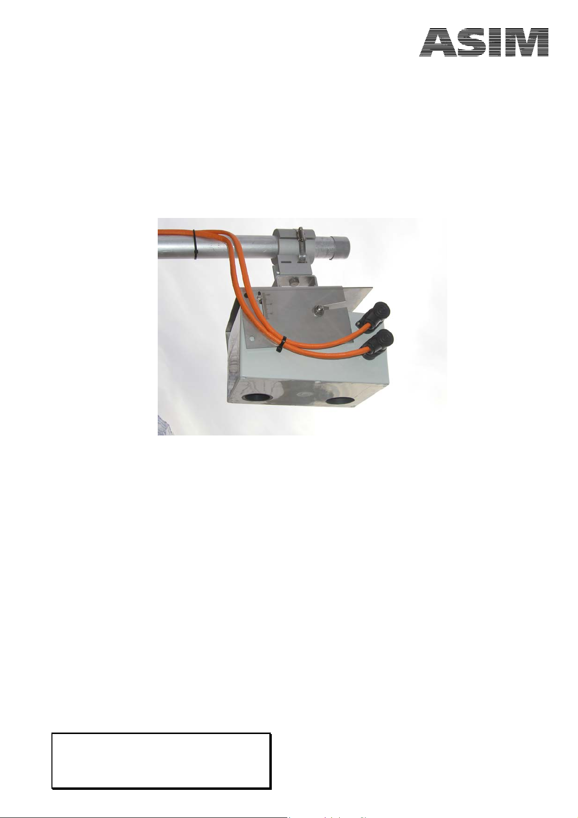
• Easy Mounting and Maintenance
• Vehicle Length Information with TT 295 / TT 298

World Headquarters
ASIM Technologies Ltd
Ziegelhof-Strasse 30
CH-8730 Uznach
Switzerland
Tel: +41-55-285 99 99
Fax: +41-55-285 99 00
e-mail: info@asim.ch
Sales Office North America
ASIM Technologies, Inc.
53 River Street Suite 304 PO Box 12
Billerica, MA 01821 U.S.A.
U.S.A
Tel: +1-978-667-5207
Toll-Free: +1-866-664-ASIM
Fax: +1-978-667-8247
e-mail: info@asim-technologies.com
www.asim-technologies.com
M-TT 290 Series_e.doc / 03.2004 / page 2 (16) www.asim-technologies.com

Table of Contents
Page
Standard Models .....................................................................................................................................................1
Highlights ................................................................................................................................................................1
1 Introduction......................................................................................................................... 4
1.1 Triple-Technology (Tri-Tech) Detection......................................................................................................4
1.1.1 Microwave Doppler Radar (MW) ................................................................................................................4
1.1.2 Ultrasonic (US)..............................................................................................................................................4
1.1.3 Passive Infrared (PIR)....................................................................................................................................4
1.2 Operation Principle of the Detectors of TT 290 Series ..............................................................................4
2 General Information ........................................................................................................... 5
2.1 Detection Areas............................................................................................................................................5
2.2 Counting / Volume.......................................................................................................................................5
2.3 Speed ............................................................................................................................................................5
2.4 Vehicle Classification ...................................................................................................................................6
2.5 Self-Check and Status Output .....................................................................................................................6
3 Planning the Main Application .......................................................................................... 7
3.1 Mounting Tips for Optimal Traffic Data Quality .......................................................................................7
3.1.1 Mounting of Detector Left or Right of the Centre of the Lane ...............................................................8
4 RS 485 Communication ....................................................................................................... 9
4.1 Interface Module and Software..................................................................................................................9
4.1.1 Product Description .....................................................................................................................................9
5 Wiring Instructions for Detectors .................................................................................... 10
5.1 Single Detector Application (Master) .......................................................................................................10
5.2 Operation of Multiple Detectors at the Same Databus ..........................................................................11
5.2.1 Master/Slave Wiring Using Two-Connector Devices ................................................................................11
5.3 Bus-Terminating Resistors .........................................................................................................................11
5.4 Electrical Connections of the Detectors of the TT 290 Series .................................................................12
5.4.1 Recommendations for Cabling .................................................................................................................12
6 Special Functions...............................................................................................................13
6.1 Power Save Mode ......................................................................................................................................13
6.2 Wrong Way Driver Mode (Wrong-Way Vehicle Detection)....................................................................13
6.3 Vehicle Profile Information .......................................................................................................................13
7 Special Traffic Situations.................................................................................................. 13
7.1 Alternating Traffic .....................................................................................................................................13
7.2 Queue / Traffic Jam....................................................................................................................................13
7.3 Stop&Go .....................................................................................................................................................14
8 Software for the Detectors of the TT 290 Series ............................................................ 14
8.1 Introduction ...............................................................................................................................................14
8.2 Applications of the Installation Software ................................................................................................14
8.3 Traffic Data.................................................................................................................................................15
9 Specification TT 290 Series ............................................................................................... 15
9.1 Mechanical Dimensions .............................................................................................................................16
10 Ordering – Information..................................................................................................... 16
11 Disclaimer .......................................................................................................................... 16
M-TT 290 Series_e.doc / 03.2004 / page 3 (16) www.asim-technologies.com

1 Introduction
1.1 Triple-Technology (Tri-Tech) Detection
The combination of the Doppler Radar, Ultrasonic and Passive Infrared detection technologies results in
excellent performance characteristics under all traffic and weather conditions.
1.1.1 Microwave Doppler Radar (MW)
The Doppler radar detects the frequency shift of microwave radiation reflected by a moving vehicle. This frequency shift is proportional to the speed of a vehicle and provides individual speed information for each
vehicle passed.
1.1.2 Ultrasonic (US)
The Ultrasonic part operates within the inaudible acoustic frequency range at approx. 50 kHz. For the detection and classification, short bursts of ultrasound are emitted and received. The time for the echo to return
provides distance information between the object’s surface and the detector. A vehicle standing in the US
detection area can be detected for an unlimited period of time thus providing true presence information.
1.1.3 Passive Infrared (PIR)
The Passive Infrared (PIR) detection principle detects moving objects as they cause radiation contrast changes
to the background. The intensity of the radiation contrast can be either positive or negative, even a fraction
of a degree can result in significant radiation contrasts.
1.2 Operation Principle of the Detectors of TT 290 Series
The detectors of the TT 290 Series combine the three technologies described above into one robust, weatherproof housing. Passing vehicles generate signals in each subsystem. These signals are separately amplified
and processed by a microcontroller, providing additional redundancy resulting in increased self-check
capabilities and high reliability.
The radar part measures the speed of each vehicle. The ultrasonic part scans the vehicle profile to determine
the vehicle classes and separates vehicles in the traffic stream for accurate count information. The multichannel PIR provides lane-selective information and triggers the ultrasonic measurement. In power-save
mode, the PIR also activates the radar.
Classification is accomplished using the length and the shape of a vehicle passed. Depending on the detectors model, vehicles are divided into two classes (TT 292), five plus one classes (TT 295) and eight plus one
classes (TT 298).
M-TT 290 Series_e.doc / 03.2004 / page 4 (16) www.asim-technologies.com
2 General Information
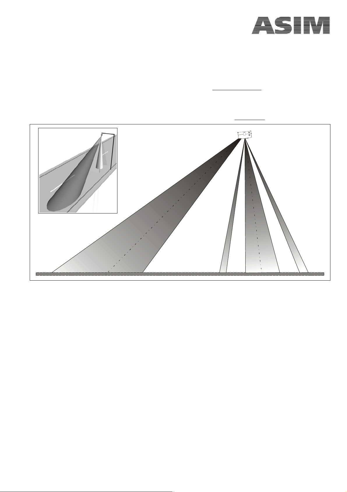
2.1 Detection Areas
The radar part of the detector features a cone shaped detection zone followed by the two PIR detection
zones enclose the cone shaped ultrasonic part. The precise geometry and range of these four detection zones
depends on the mounting height of the detector. It is designed to cover one lane
mounted above the lane on a bridge or other overhead construction (see figure).
The angles between the radar cone, the ultrasonic cone and the two PIR zones are fixed and thus determine
the detection geometry. The distances are interdependent, defined through mounting height and alignment
angle of the detector enclosure relative to the lane surface. Please consult chapter 3.1
provided the detector is
for further details.
Radar
PIR
US
PIR
2.2 Counting / Volume
The combination of the three subsystems ensures highly accurate volume information of all vehicle classes.
Occasional over or under counting can occur in special situations such as slow-moving Stop&Go traffic.
2.3 Speed
During normal traffic flow, the speed of each vehicle is obtained. These individual values can have some
tolerances, average values however are deemed to be very accurate especially if the detector is calibrated
using a reference system: If speed information is systematically inaccurate, the detector can be adjusted by
the corrective v-factor in the installation program ASIM-T.exe without a hardware alignment.
M-TT 290 Series_e.doc / 03.2004 / page 5 (16) www.asim-technologies.com

2.4 Vehicle Classification
Each vehicle moving or through the detection areas can be detected and classified individually. As classification criteria of the standard models, the German TLS specifications for two classes (car and lorry / truck), five
plus one and eight plus one classes are used as a guideline.
The classification and number of classes depends on the model and is shown in the table below:
In Stop&Go traffic or similar situations the classification accuracy, particularly for more than 2 classes, is
severely impaired.
Model TT 292 TT 295 TT 298
Class Description 2 5+1 8+1
car
7
Other classifications are available upon request.
motorcycle
delivery van
not identified
lorry / truck
lorry / truck with trailer
articulated lorry / semi-trailer
bus
car with trailer
1
32
6 6
3 3
4
33
5 5
2 2
10
11
8
9
2.5 Self-Check and Status Output
The detector features an internal self check facility whereby the data pattern and time criteria of all major
functions are permanently checked and processed.
Failure of any detection subsystem of the unit will result in a fault condition, which is identified in the status
byte in the protocol. This status information has to be monitored permanently during operation of the
detector.
The ‘scope’ function in the ASIM-T.exe installation software indicates the status as follows:
Value Status Output
1 Radar fault
2 IR1 fault
4 IR2 fault
8 Ultrasonic fault
16 Wrong-way driver
32 Queue / Traffic jam
Combination of different errors can occur and are evident as follows: status byte value of 33 corresponds to
32 (queue) + 1 (Radar fault).
Further information regarding the status output is available in the telegram specifications. Information
about the Wrong-Way Driver is available under chapter 6.2
M-TT 290 Series_e.doc / 03.2004 / page 6 (16) www.asim-technologies.com
.
 Loading...