

Page 1

ADPRO®
FastTrace™ 2
Series
Hardware
Installation Manual
March 2015
Doc. 21790_05
Firmware version XOa 3.00.0003
Page 2

Page 3
ADPRO® FastTrace™ 2 Series Hardware Installation Manual
21790_05 3
Disclaimer
The contents of this document are provided on an "as is" basis. No representation or warranty (either express or implied) is made as to the completeness,
accuracy or reliability of the contents of this document. The manufacturer reserves the right to change designs or specifications without obligation and
without further notice. Except as otherwise provided, all warranties, express or implied, including without limitation any implied warranties of merchantability
and fitness for a particular purpose are expressly excluded.
Intellectual Property and Copyright
This document includes registered and unregistered trademarks. All trademarks displayed are the trademarks of their respective owners. Your use of this
document does not constitute or create a license or any other right to use the name and/or trademark and/or label. This document is subject to copyright
owned by Xtralis. You agree not to copy, communicate to the public, adapt, distribute, transfer, sell, modify, or publish any contents of this document
without the express prior written consent of Xtralis.
General Warning
This product must only be installed, configured and used strictly in accordance with the General Terms and Conditions, User Manual and product
documents available from Xtralis. All proper health and safety precautions must be taken during the installation, commissioning, and maintenance of the
product. The system should not be connected to a power source until all the components have been installed. Proper safety precautions must be taken
during tests and maintenance of the products when these are still connected to the power source. Failure to do so or tampering with the electronics inside
the products can result in an electric shock causing injury or death and may cause equipment damage. Xtralis is not responsible and cannot be held
accountable for any liability that may arise due to improper use of the equipment and/or failure to take proper precautions. Only persons trained through an
Xtralis accredited training course can install, test and maintain the system.
Liability
You agree to install, configure, and use the products strictly in accordance with the User Manual and product documents available from Xtralis.
Xtralis is not liable to you or any other person for incidental, indirect, or consequential loss, expense or damages of any kind including without limitation,
loss of business, loss of profits, or loss of data arising out of your use of the products. Without limiting this general disclaimer the following specific warnings
and disclaimers also apply:
Fitness for Purpose
You agree that you have been provided with a reasonable opportunity to appraise the products and have made your own independent assessment of the
fitness or suitability of the products for your purpose. You acknowledge that you have not relied on any oral or written information, representation, or advice
given by or on behalf of Xtralis or its representatives.
Total Liability
To the fullest extent permitted by law that any limitation or exclusion cannot apply, the total liability of Xtralis in relation to the products is limited to:
(i) in the case of services, the cost of having the services supplied again; or
(ii) in the case of goods, the lowest cost of replacing the goods, acquiring equivalent goods or having the goods repaired.
Indemnification
You agree to fully indemnify and hold Xtralis harmless for any claim, cost, demand, or damage (including legal costs on a full indemnity basis) incurred or
which may be incurred arising from your use of the products.
Miscellaneous
If any provision outlined above is found to be invalid or unenforceable by a court of law, such invalidity or unenforceability will not affect the remainder which
will continue in full force and effect. All rights not expressly granted are reserved.
Document Conventions
The following typographic conventions are used in this document.
Convention
Description
Bold
Used to denote: emphasis.
Used for names of menus, menu options, toolbar buttons.
Italics
Used to denote: references to other parts of this document or other documents. Used for the result of an action.
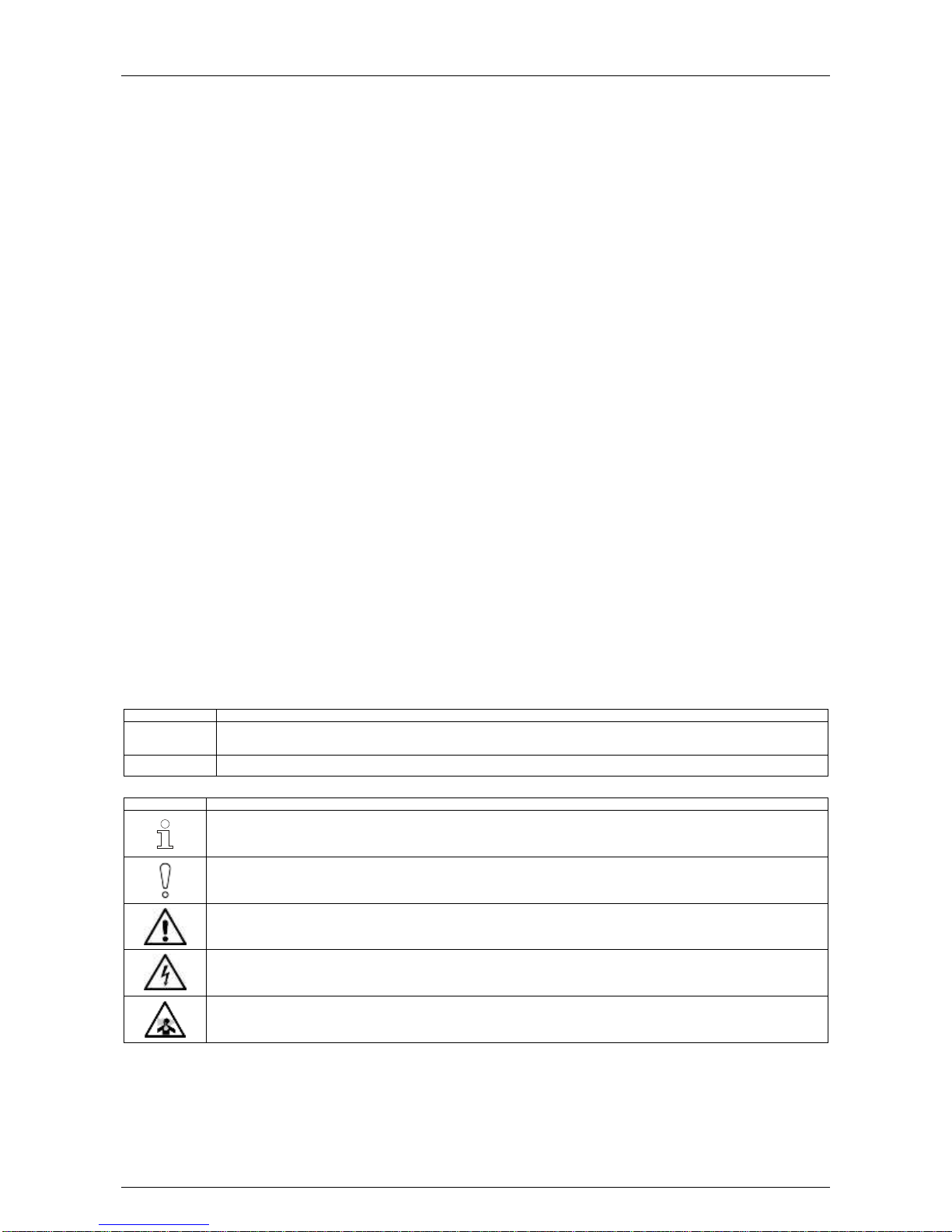
The following icons are used in this document.
Icon
Description
Note. This icon indicates information of special interest that will help the reader make full use of the product, optimise
performance, etc. Failure to read the note will not result in physical harm to the reader, or damage to equipment or data.
Caution! This icon indicates danger to equipment. The danger can be loss of data, physical damage to the equipment, or permanent
corruption of configuration details.
Warning! This icon indicates danger of physical harm to the reader. Not following instructions may lead to death or permanent injury.
Warning! This icon indicates danger of electric shock. This may lead to death or permanent injury.
Warning! This icon indicates that there is a danger of inhaling dangerous substances. This may lead to death or permanent injury.
Page 4
Hardware Installation Manual ADPRO® FastTrace™ 2 Series
4 21790_05
Trade Name Statement
ADPRO is a registered trademark of Xtralis Pty Ltd.
Contact Us
UK and Europe +44 1442 242 330 D-A-CH +49 431 23284 1 The Americas +1 781 740 2223
Middle East +962 6 588 5622 Asia +86 21 5240 0077 Australia and New Zealand +61 3 9936 7000
www.xtralis.com
Environmental Information
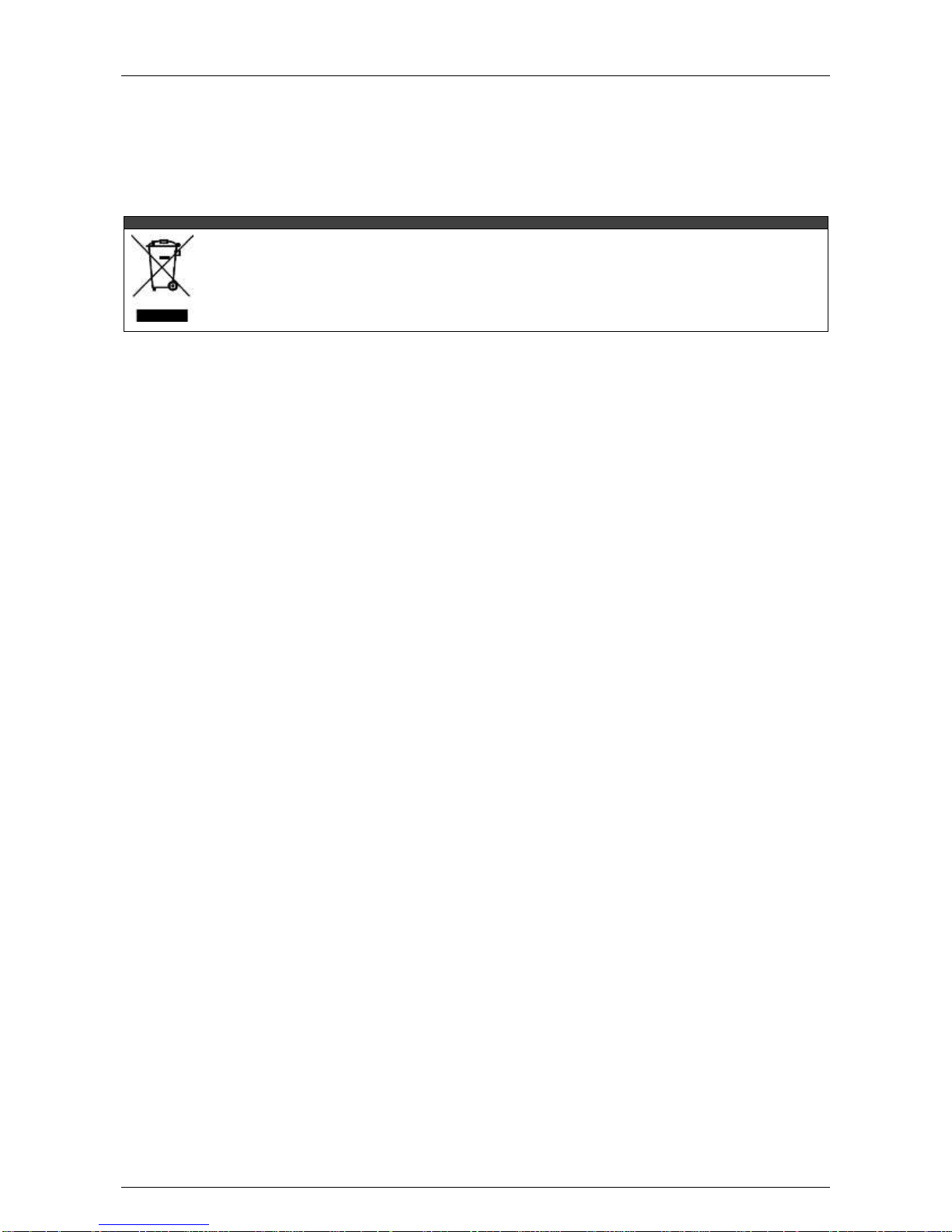
The crossed-out wheeled bin means that within the European Union the product must be taken to separate collection at the product
end of life. This applies to the device but also to any accessories marked with this symbol. Do not dispose of these products as
unsorted municipal waste.
If you need more information on the collection, reuse, and recycling systems please contact your local waste administration. You
can also contact us for more information on the environmental specifications of our products.
Page 5

ADPRO® FastTrace™ 2 Series Hardware Installation Manual
21790_05 5
Contents
1 Technical Specifications ...................................................................................................................... 9
2 Specific FastTrace Configurations .................................................................................................... 12
2.1 FastTrace 2 Lite ......................................................................................................................... 12
2.2 FastTrace 2X .............................................................................................................................. 12
2.3 FastTrace 2E .............................................................................................................................. 13
2.4 System License ......................................................................................................................... 13
3 Hard Disks ............................................................................................................................................ 15
3.1 Required Hard Disk Capacity ................................................................................................... 15
3.2 Adding/Replacing a Hard Disk ................................................................................................. 15
3.3 Retrieving Hard Disk Information ............................................................................................ 15
3.3.1 Using the ta,smart Command ........................................................................................ 15
3.3.2 Using the XOa Client Software ...................................................................................... 16
3.4 Material List (for 1 Hard Disk) .................................................................................................. 17
3.5 Adding Hard Disks with an Intel DH55TC Motherboard ........................................................ 17
3.6 Adding Hard Disks with an Intel DH61BE Motherboard ........................................................ 20
3.7 Boot Problems after Adding a HDD with the DH61BE Motherboard ................................... 23
3.8 Adding Hard Disks with a MiTAC PH10LU Motherboard ...................................................... 24
3.9 RAID 1 Support .......................................................................................................................... 27
3.9.1 About RAID 1 ................................................................................................................. 27
3.9.2 Activating RAID 1 ........................................................................................................... 28
4 Fan Speed Selection ........................................................................................................................... 29
5 Front LED Indicators ........................................................................................................................... 30
5.1 Overview .................................................................................................................................... 30
5.2 LED Connections without Main I/O Card ................................................................................ 30
5.3 LED Connections with Main I/O Card ...................................................................................... 31
6 Required Motherboard ........................................................................................................................ 32
6.1 Overview .................................................................................................................................... 32
6.2 BIOS Settings ............................................................................................................................ 32
6.2.1 Intel DG31PR or Intel DG41TY Motherboard ................................................................ 32
6.2.2 Intel DH55TC Motherboard ............................................................................................ 32
6.2.3 Intel DH61BE Motherboard ............................................................................................ 33
6.2.4 MiTAC PH10LU Motherboard ........................................................................................ 33
6.3 Replacing the Motherboard ...................................................................................................... 33
6.4 Replacing the Motherboard Battery ........................................................................................ 33
7 Extension Boards ................................................................................................................................ 34
7.1 Overview .................................................................................................................................... 34
7.2 General Rules ............................................................................................................................ 35
7.3 Available Configurations .......................................................................................................... 35
7.3.1 With Intel DG31PR Motherboard ................................................................................... 35
7.3.2 With Intel DG41TY Motherboard ................................................................................... 37
7.3.3 With Intel DH55TC Motherboard ................................................................................... 39
7.3.4 With Intel DH61BE Motherboard ................................................................................... 41
7.3.5 With MiTAC PH10LU Motherboard................................................................................ 46
Page 6

Hardware Installation Manual ADPRO® FastTrace™ 2 Series
6 21790_05
8 Main and Extension I/O Cards ............................................................................................................ 48
8.1 Features ..................................................................................................................................... 48
8.2 Possible Configurations ........................................................................................................... 48
8.3 Ordering Information ................................................................................................................ 49
8.4 Physical Position ...................................................................................................................... 49
8.5 Settings on the Main I/O Card .................................................................................................. 50
8.6 Installation ................................................................................................................................. 50
8.7 Reset Signal Details .................................................................................................................. 53
8.8 Adding an Extension I/O Card ................................................................................................. 54
8.8.1 Settings on the Extension I/O Card ............................................................................... 54
8.8.2 Installation ...................................................................................................................... 54
8.9 Adding a Second Set of I/O Cards ........................................................................................... 55
8.10 Connection of Inputs/Outputs ................................................................................................. 55
8.11 Configuring the Internal I/O Cards .......................................................................................... 56
8.12 Input Circuits ............................................................................................................................. 56
9 Main and Extension I/O Cards Next Generation ............................................................................... 57
9.1 Features ..................................................................................................................................... 57
9.2 Possible Configurations ........................................................................................................... 57
9.3 Ordering Information ................................................................................................................ 57
9.4 Material List ............................................................................................................................... 58
9.4.1 Main I/O Card with Mounting Set (#39544000) ............................................................. 58
9.4.2 Extension I/O Card with Mounting Set (#39544010) ..................................................... 60
9.5 Physical Position ...................................................................................................................... 60
9.6 Settings on the Main I/O Card .................................................................................................. 62
9.7 Installation ................................................................................................................................. 62
9.8 Reset Signal Details .................................................................................................................. 65
9.9 Adding an Extension I/O Card ................................................................................................. 66
9.9.1 Settings on the Extension I/O Card ............................................................................... 66
9.9.2 Installation ...................................................................................................................... 66
9.10 Adding a Second Set of I/O Cards ........................................................................................... 67
9.11 Connection of Inputs/Outputs ................................................................................................. 67
9.11.1 Overview of Inputs and Outputs .................................................................................... 67
9.11.2 Connecting Inputs/Outputs ............................................................................................ 68
9.11.3 Cable Strain Relief ......................................................................................................... 68
9.12 Configuring the Internal I/O Cards .......................................................................................... 68
9.13 Input Circuits ............................................................................................................................. 69
10 Required Encoder (A/V) Card ............................................................................................................. 70
10.1 Number of Cameras .................................................................................................................. 70
10.2 Technical Specifications of Analogue Cameras .................................................................... 70
10.3 Replacing a Video Card ............................................................................................................ 71
10.4 Adding a Video Card ................................................................................................................. 72
10.5 Video Input Termination (75 Ohm/High Impedance) ............................................................. 73
11 HIPI Card for IP Cameras .................................................................................................................... 74
11.1 Ethernet Settings ...................................................................................................................... 74
11.2 Adding a HIPI Card .................................................................................................................... 76
11.2.1 Placement on the Intel DG31PR Motherboard .............................................................. 76
11.2.2 Placement on the Intel DG41TY Motherboard .............................................................. 76
11.2.3 Placement on the Intel DH55TC Motherboard .............................................................. 77
11.2.4 Placement on the Intel DH61BE Motherboard .............................................................. 77
11.3 Configuring the HIPI Card ........................................................................................................ 77
Page 7

ADPRO® FastTrace™ 2 Series Hardware Installation Manual
21790_05 7
12 Ethernet Card ....................................................................................................................................... 78
12.1 Installation ................................................................................................................................. 78
12.2 Ethernet Settings ...................................................................................................................... 78
13 DTC Card .............................................................................................................................................. 79
14 PTZ Cameras ........................................................................................................................................ 80
14.1 Serial PTZ on MIO Card ............................................................................................................ 80
14.2 PTZ via DTC ............................................................................................................................... 81
14.3 PTZ via USB Converters ........................................................................................................... 81
15 Presidium ............................................................................................................................................. 82
16 Modems ................................................................................................................................................ 83
17 Audio .................................................................................................................................................... 84
17.1 Audio IN ...................................................................................................................................... 84
17.1.1 Setup .............................................................................................................................. 84
17.1.2 Recommended Microphones ......................................................................................... 84
17.2 Audio OUT .................................................................................................................................. 87
17.2.1 Setup .............................................................................................................................. 87
17.2.2 Connecting the VM22A Audio Switch ............................................................................ 88
18 Connecting PIRs .................................................................................................................................. 89
18.1 Required PIR Firmware ............................................................................................................. 89
18.2 Connecting the PIRs ................................................................................................................. 89
18.2.1 Connecting the PIR Detector Directly to the Main I/O Card .......................................... 89
18.2.2 Connecting the PIR Detector Using the USB to RS-485 8-Channel
Distribution Unit.............................................................................................................. 91
18.2.3 Connecting the PIR Detector Using a USB to Serial Port RS-485 Converter ............... 92
19 Network Load ....................................................................................................................................... 94
20 Current Consumption ......................................................................................................................... 95
21 Retrieving the IP Address ................................................................................................................... 96
22 Diagnostics .......................................................................................................................................... 97
22.1 Retrieving Traces ...................................................................................................................... 97
22.2 Retrieving Reports .................................................................................................................... 99
23 FastTrace 2 Web Pages .................................................................................................................... 101
24 Maintenance ....................................................................................................................................... 102
24.1 Replacing the Filters ............................................................................................................... 102
24.2 Cleaning the FastTrace 2 Server ........................................................................................... 102
25 Product Labelling .............................................................................................................................. 103
25.1 Labels ....................................................................................................................................... 103
25.2 Product Number Structure ..................................................................................................... 104
25.2.1 FastTrace 2 and FastTrace 2X Units ........................................................................... 104
25.2.2 FastTrace 2E Units ...................................................................................................... 105
25.3 Declaration of Conformity ...................................................................................................... 106
Appendix A: Abbreviations......................................................................................................................... 107
Page 8

Hardware Installation Manual ADPRO® FastTrace™ 2 Series
8 21790_05
Page 9

ADPRO® FastTrace™ 2 Series Hardware Installation Manual
21790_05 9
1 Technical Specifications
The FastTrace 2 unit is the current video security system within the ADPRO
®
FastTrace™ series. It has been
developed as a high performance video security unit that can either be managed by CMS software
(e.g. M3000) or by the ADPRO XOa client.
Operating system
PC platform – Linux OS
Network protocols
TCP, UDP, FTP, Telnet, HTTP, SMTP, RTSP, RTP
Bandwidth
Remotely adjustable: compression, fps, and quality.
You can specify a bandwidth limit.
Bandwidth consumption
6 fps CIF/SIF: 70 kbps
12 fps 4CIF/SIF: 400 kbps in optimal quality
Software updates
Local and remote
Maximum number of
cameras
FastTrace 2/2X: 16 (total of analogue and IP cameras)
FastTrace 2E: 32 (total of analogue and IP cameras)
Analogue cameras (*)
FastTrace 2/2X: 4, 8, 12, or 16 analogue A/V inputs
FastTrace 2E: 4, 8, 12, 16, or 20 analogue A/V inputs
Video:
PAL or NTSC
BNC connectors (1.0 Vp-p; 75 ohm)
Max. cable length: 350 m (RG59); 610 m (RG11)
Audio:
1 input per analogue camera
Screw connectors
Input level: 2.0 Vp-p; 1000 ohm
Analogue cameras
Video resolution PAL
QCIF (176 x 144)
CIF (352 x 288)
2CIF (704 x 288)
DCIF (528 x 384) (not available with DS42xx A/V cards)
4CIF (704 x 576)
Analogue cameras
Video resolution NTSC
QSIF (176 x 120)
SIF (352 x 240)
2SIF (704 x 240)
DSIF (528 x 320) (not available with DS42xx A/V cards)
4SIF (704 x 480)
Analogue cameras
images/second PAL
CIF, 2CIF, DCIF: 25 fps / camera
4CIF: 15 fps / camera (25 fps with DS42xx A/V cards)
Analogue cameras
images/second NTSC
QSIF, SIF, 2SIF, DSIF: 30 fps / camera
4SIF: 15 fps / camera (25 fps with DS42xx A/V cards)
IP cameras (**)
Up to 20 IP cameras on a dedicated IP network.
Optional network interface required:
1 HIPI card per 8 IP cameras
FastTrace 2E: 1 Ethernet card for up to 32 IP cameras (with XOa software,
Intel DH61BE or MiTAC PH10LU motherboard and 4 GB RAM or more)
With MiTAC PH10LU motherboard: no separate network card required.
Only H.264 video streaming can be used.
Audio input is supported.
Video resolution and
images/second
Depends solely on the IP camera type.
Maximal HD/MP resolution.
Page 10
Hardware Installation Manual ADPRO® FastTrace™ 2 Series
10 21790_05
Video output
VGA connector; adjustable resolution (up to SXGA)
With MiTAC PH10LU motherboard: DVI-I or DP (DisplayPort)
Video compression
H.264
Audio compression
The audio compression depends on the camera type.
Bandwidth
Remotely adjustable: compression, fps, and quality.
You can specify a bandwidth limit.
Bandwidth consumption
6 fps CIF/SIF: 70 kbps
12 fps 4CIF/SIF: 400 kbps in optimal quality
Recording type
Continuous, on event (e.g. input, motion detection), alarm over IP (S3100),
Presidium
Storage
Max. 4 x 4 TB SATA hard disks. RAID 1 support
Note
You can connect a portable DVD writer to export video
sequences. Use the USB connector on the front, or the
USB connectors on the back of the FastTrace 2.
Remote visualisation
Internet Explorer; Windows XP, Windows Vista, Windows 7,
Windows Server 2003, Windows Server 2008
Management
Internet Explorer (installs XOa client software)
VSKWin software
M3000 software
VideoCentral Platinum
HeiTel EMS software
third-party CMS software
Power supply
100–240 VAC, 50/60 Hz (+80 % efficiency)
Note
The video system must be connected to a
100-230 VAC/16 A mains outlet with proper earth, applying
a separate, locally approved power cord.
Operating temperature
5–40 °C (see Fan Speed Selection on page 29)
Humidity
20–93 % RH (non-condensing)
Dimensions
445 x 132.5 x 300 mm (W x H x D) without flanges
You can fix rubber feet on the bottom. The height is then increased by 2.5 mm.
(*) With an ENTRY system license you can only use 4 analogue cameras, because this is the maximum
number of analogue cameras that is supported by the ENTRY system license. This is for instance the case
with the ADPRO FastTrace 2 Lite.
(**) With an ENTRY system license you cannot use IP cameras, because this is not supported by this
specific system license. This is for instance the case with the ADPRO FastTrace 2 Lite.
Note
You are not allowed to draw any other streams from the IP cameras than those destined for the
FastTrace 2. If you do need to draw other streams from the IP camera for any reason, use the
single stream mode (for more information, see the XOa Client Software User Manual).
If you have to use streams for other applications as well, then also use the single stream mode.
Page 11
ADPRO® FastTrace™ 2 Series Hardware Installation Manual
21790_05 11
Multi-site FastTrace 2 configuration is possible:
Integration of up to 10,000 FastTrace 2 video security systems
Remote video and audio, live video, and consultation of recordings
Compatible with FOXnet®Plus, FALCONnet, S3100, Presidium, VSKwin®, VCP, and M3000
SDK for third-party integration
Note
Please use the reference numbers in this document (for example #17434080) for ordering parts
with Xtralis, or for identifying the correct required part. If a part is indicated by a reference
number ending in an asterisk (for example #1729121*), this indicates that several variants exist
for the part (for example reference numbers #17291210 and #17291211). These variants are
interchangeable. Any variant is suitable for the task described.
Page 12
Hardware Installation Manual ADPRO® FastTrace™ 2 Series
12 21790_05
2 Specific FastTrace Configurations
2.1 FastTrace 2 Lite
The FastTrace 2 Lite has been designed, developed and manufactured as a complete FastTrace 2 video
security system, but the Entry system license that is included, limits the number of supported cameras to a
maximum of 4 analogue cameras.
Also note that the FastTrace 2 Lite can only operate with analogue cameras; it does not support IP cameras.
The FastTrace 2 Lite comes with an Entry system license. It is not possible to expand the video system with
new licenses and/or extra extension boards.
a
FastTrace 2
FastTrace 2 Lite
Full system license
TX (transmission) only license
Entry level license
For more information on the system licenses, see System License on page 13.
For more information on FastTrace 2 Lite, see the commercial datasheet. You can download the datasheet
from our website www.xtralissecurity.com (logon not required for commercial datasheets).
Note
The FastTrace 2 Lite has become obsolete. Xtralis no longer provides it.
2.2 FastTrace 2X
The FastTrace 2X has been developed as a more powerful video system with higher performance and more
efficient operation.
The major difference is that the FastTrace 2X supports up to 16 analytic channels, while the FastTrace 2 is
limited to a maximum of 4 analytic streams.
The FastTrace 2X comes with a full or TX-only system license.
FastTrace 2
FastTrace 2X
Full system license
TX (transmission) only license
Entry level license
For more information on the system licenses, see System License on page 13.
Note
The FastTrace 2X requires software version 2.6 or higher.
Wherever in this document the term FastTrace 2 is used, you can assume that the term refers
to both the FastTrace 2 and the FastTrace 2X, unless specifically mentioned otherwise.
Note
The FastTrace 2X has become obsolete. Xtralis no longer provides it.
Page 13
ADPRO® FastTrace™ 2 Series Hardware Installation Manual
21790_05 13
2.3 FastTrace 2E
The FastTrace 2E is the latest hardware in the ADPRO® FastTrace™ 2 series. It has been developed as a
powerful video system with high performance and more efficient operation to replace the former FastTrace
units. The FastTrace 2E has up to 20 analogue video inputs, up to 32 IP video inputs, and supports up to
32 analytic channels.
Although the XOa 3 software technically allows for 32 IP channels, these 32 channels are only available on
FastTrace 2E models with an Intel DH61BE or MiTAC PH10LU motherboard, and 4 GB RAM or more. On
other models, maximum 16 IP channels are available.
Furthermore, to use the 32 IP channels, the FastTrace 2E requires a new system license. Use Xchange to
install the new license. For instructions, see Field Alert #6 – Upgrading to Xoa 3.
Remember to purchase and install additional IP licenses if required.
You can purchase the FastTrace 2E with a full or TX-only system license.
FastTrace 2
FastTrace 2E
Full system license
TX (transmission) only license
Entry level license
For more information on the system licenses, see System License on page 13.
Note
The FastTrace 2E requires software version 2.10 or higher.
Wherever in this document the term FastTrace 2 is used, you can assume that the term refers
to both the FastTrace 2 and the FastTrace 2E, unless specifically mentioned otherwise.
2.4 System License
From version 2.00, all ADPRO video systems require a system license.
Note
Applications such as IntrusionTrace, LoiterTrace…, IP channels, and the video encoder cards
require a separate license. They are not included in the system license.
There are 3 types of system licenses available:
FULL: all features of the video system are available.
ENTRY(*): all features are available, with these restrictions:
- You can use only 4 analogue cameras (no IP camera support).
- You can use only 1 hard disk.
- You can only use 1 MIO card (and no EIO cards).
TRANSMITTER (TX) only: all features are available, but continuous recording is not allowed and
recording on event is fixed to 5 seconds pre-recording, 10 seconds event recording, and 0 seconds postrecording. Furthermore, event recording stops when the limit of 16,000 events has been reached.
(*) The ENTRY system license is not available for the FastTrace 2X or FastTrace 2E configuration.
A FastTrace 2 video system running without system license will behave as a video system with a FULL
license for 5 days. However, the system informs the user of the license error via the event message
0013 – [SYST] – SYSTEM LICENSE ERROR, and via a popup window at each connection with the XOa
client.
After that period of 5 days, the video system enters a locked-down state, and refuses all connections for
live streams and recordings. All active configured recordings continue on the video system. During this
locked-down state, the XOa client shows only the About window (so that you can retrieve the necessary
information to order a new license) and the Transfer window (so that you can upload a license to the
Page 14

Hardware Installation Manual ADPRO® FastTrace™ 2 Series
14 21790_05
FastTrace 2 video system). For more information on uploading licenses, see the XOa Client Software User
Manual.
Note
The system license is locked on the FastTrace 2 motherboard and is therefore system specific:
the license must include the correct MAC address.
When you upload the system license and your unit already has other licenses (e.g. an encoder
license, a LoiterTrace license…), your video system merges all these licenses together in one
license file. For backup and archiving, you only need to download one file.
Page 15
ADPRO® FastTrace™ 2 Series Hardware Installation Manual
21790_05 15
3 Hard Disks
3.1 Required Hard Disk Capacity
As there are lots of configuration possibilities, Xtralis has a hard disk space calculator available. You can find
this hard disk space calculator on the CD/DVD provided with your FastTrace 2 video system, or you can
download it from our website www.xtralissecurity.com. Make sure you log on with sufficient download rights.
Note
The calculator is an estimating tool only. Figures are purely indicative. The real requirements of
the hard disk capacity depend on scene content.
3.2 Adding/Replacing a Hard Disk
If you receive error messages from your hard disk in the Status screen of the XOa client, you may need to
replace the faulty hard disk.
If the system is running out of disk space, you can add a new hard disk without removing any of the hard
disks in use. You can install up to 4 hard disks.
Note
When using an Entry system license, you can use only 1 hard disk. For example, with the
ADPRO FastTrace 2 Lite.
Note
It is possible to mount a hard disk coming from another unit into a new unit. If you do this, you
can play back video that has been recorded by the other FastTrace 2 unit.
Take the following restrictions into account:
Make sure that the new unit has the same configuration concerning the number of video
channels as the unit from which the hard disk was taken.
Xtralis recommends to immediately put the number of days recording to 0 (in the Recording
Behaviour screen, Maximum days recording). This prevents overwriting of valuable data.
Clear all recording conditions in the recording behaviour. This prevents overwriting of valuable
data.
Do not mix hard disks from different FastTrace 2 units into one, because this will result in
unpredictable behaviour. Do not add the old disk to the new unit, but replace the disk(s) in the
new unit by the old disk(s).
3.3 Retrieving Hard Disk Information
You can retrieve hard disk information and identify possibly hard disks using the Telnet ta,smart command,
or using the XOa client software.
3.3.1 Using the ta,smart Command
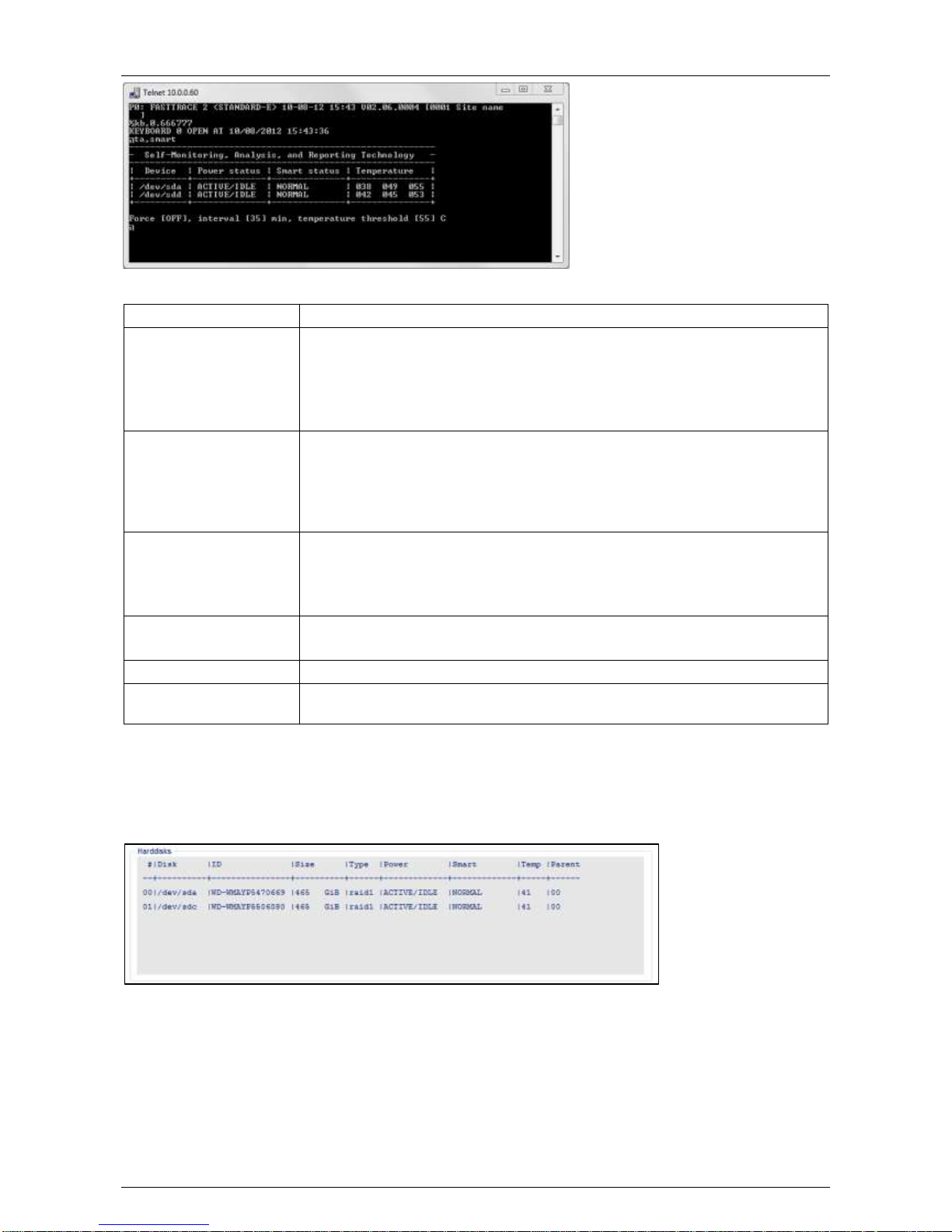
SMART stands for Self-Monitoring Analysis and Reporting Technology. Execute the ta,smart command in a
Telnet session to obtain the SMART information for all hard disks in the FastTrace 2 video system.
Page 16
Hardware Installation Manual ADPRO® FastTrace™ 2 Series
16 21790_05
The screen displays the following information:
Device
Indicates the specific hard disk
Power status
The power status column displays one of the following statuses:
ERROR there is a problem retrieving the power status of the drive
ACTIVE/IDLE drive operates normally
STANDBY drive is in low power mode (drive is in spin-down status)
SLEEPING drive is in lowest power mode (drive is completely shut down)
Smart status
The smart status column displays one of the following statutes:
ERROR drive is failing
ALERT there is a problem retrieving SMART info from the drive, or the
drive may be in the process of failing
NORMAL no problems found with the drive
Temperature
The temperature column displays from left to right:
the minimum temperature of the disk
the current temperature of the disk
the maximum temperature of the disk
Force [ON/OFF]
ON = SMART is checked on disk in STANDBY or SLEEPING mode
OFF = SMART is only checked on disks in ACTIVE/IDLE mode
Interval
Indicates the interval (in minutes) between SMART checks.
Temperature threshold
If the disk temperature is higher than this threshold, the system generates the
alarm I102: 'SMART HDD ALERT TEMP'.
3.3.2 Using the XOa Client Software
If you have more than one hard disk installed in your server, you can check which hard disk is causing the
alarm messages in the XOa client via System > Maintenance > Harddisks. The Smart column shows the
operational status of the hard disks.
Page 17
ADPRO® FastTrace™ 2 Series Hardware Installation Manual
21790_05 17
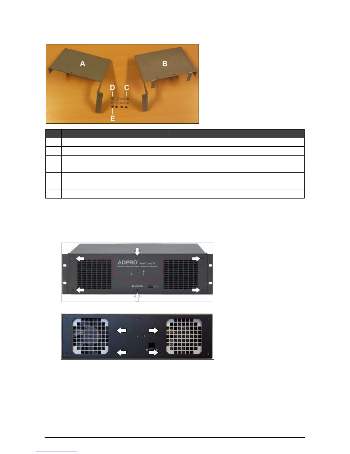
3.4 Material List (for 1 Hard Disk)
Part
Amount+ Reference Number
A
Support for disk 2
1 x #1729121*
B
Support for disk 3 and 4
1 x #1729122*
C
Disk screws
4 x #17434080 or #17434060
D
Dented washers M4
4 x #17720050
E
Mounting screws
4 x #17439080
SATA cable
1 x #1652087*
Tie-wraps
1 x #17730220
3.5 Adding Hard Disks with an Intel DH55TC Motherboard
To add one or more hard disks with an Intel DH55TC motherboard, proceed as follows:
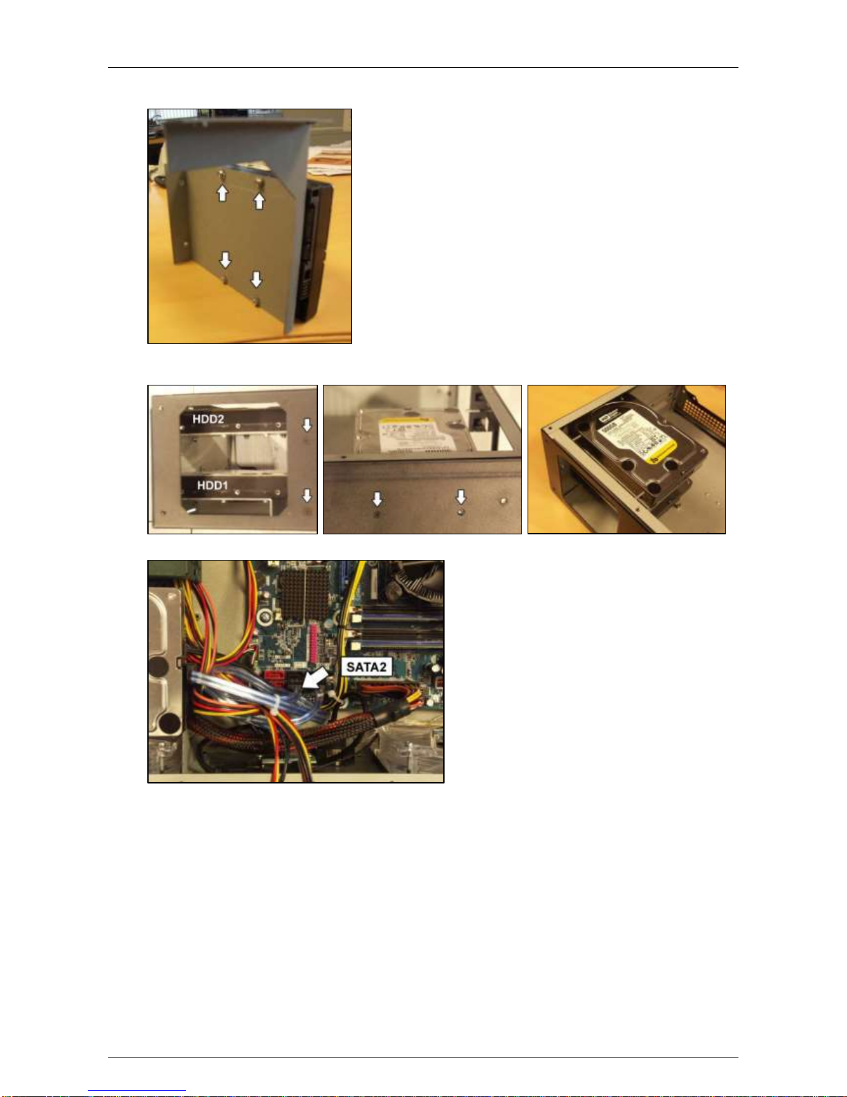
1. Switch off the power supply and remove the lid. Then remove the front plate.
You can now see the mounting holes for the disk bays:
Page 18
Hardware Installation Manual ADPRO® FastTrace™ 2 Series
18 21790_05
2. Fix the second disk to the support #1729121* with the screws #17434080 or #17434060 and dented
washers M4 #17720050.
3. Fix the support to the casing with 4 screws (#17439080): 2 at the front, and 2 at the left side of the
casing.
4. Connect the disk to the SATA2 connector on the motherboard with the SATA cable (#1652087*).
5. For the power supply to the disk, connect the remaining SATA power connector on the power cable of
disk 1 (not the one on the tail end; that one is reserved for the D.O.M.) to the disk.
6. If you need to add more disks, continue with the next step.
If you do not need to add more disks, skip to step 12.
Page 19
ADPRO® FastTrace™ 2 Series Hardware Installation Manual
21790_05 19
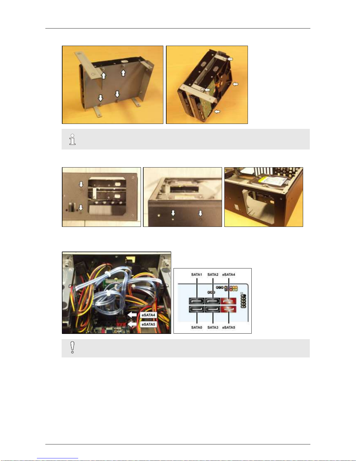
7. Fix the third disk on the top side of the support for disk 3 and 4. If necessary, fix the fourth disk on the
bottom side of the same support.
Note
Make sure to install the disk on the top side of the support first.
8. Fix the support to the casing with 4 screws (#17439080): 2 at the front, and 2 at the right side of the
casing.
9. Connect disk 3 to the eSATA4 connector on the motherboard with a SATA cable (#1652087*).
10. If necessary, connect disk 4 to the eSATA5 connector on the motherboard with a SATA cable
(#1652087*).
Caution!
Do not bend the SATA cables too sharply to prevent cable damage.
11. For the power supply to disks 3 and 4, take an unused SATA power cable and connect it as follows:
- Use the connector that is closest to the power supply for disk 4.
- Use the next connector for disk 3.
Page 20
Hardware Installation Manual ADPRO® FastTrace™ 2 Series
20 21790_05
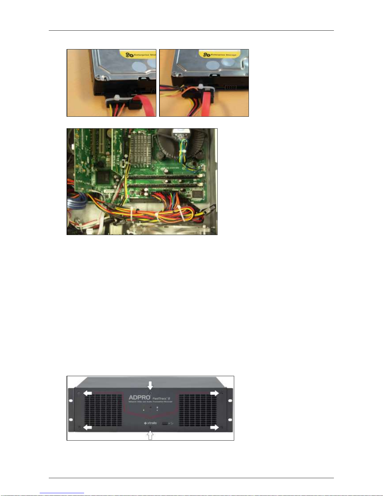
12. If the SATA cables do not have a locking mechanism, use tie-wraps to secure the cables on the
disk(s) in the following way:
13. If there are unused cables left, bundle them with tie-wraps.
14. Fix the front plate (#17011610) on the base with the screws (#17444080).
Put the cover in place and secure with 10 screws (#17439080).
15. Connect a monitor/screen and keyboard to the server. Switch on the power supply and wait for the
boot window to appear.
16. Select XOa Installer and press Enter.
17. The next step depends on the type of hard disk that you are installing:
- If the added hard disk is new, choose Update current system > Manage recording disks and
select the new hard disk in the list. Press Enter. Then choose (using the tab key) Format and use
selected disks. Choose Main Menu and choose Reboot.
- If the added hard disk comes from another server unit, choose Update current system > Mount
all recording disks. Press Enter. Then choose Main Menu and choose Reboot.
The video system now reboots. After rebooting, the new hard disk is ready for use.
3.6 Adding Hard Disks with an Intel DH61BE Motherboard
To add one or more hard disks with an Intel DH61BE motherboard, proceed as follows:
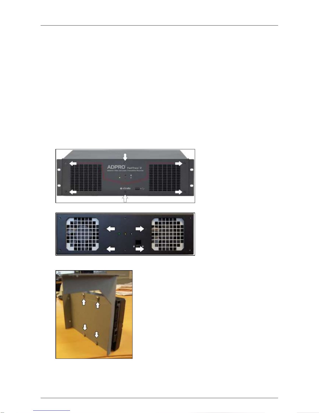
1. Switch off the power supply and remove the lid. Then remove the front plate.
Page 21
ADPRO® FastTrace™ 2 Series Hardware Installation Manual
21790_05 21
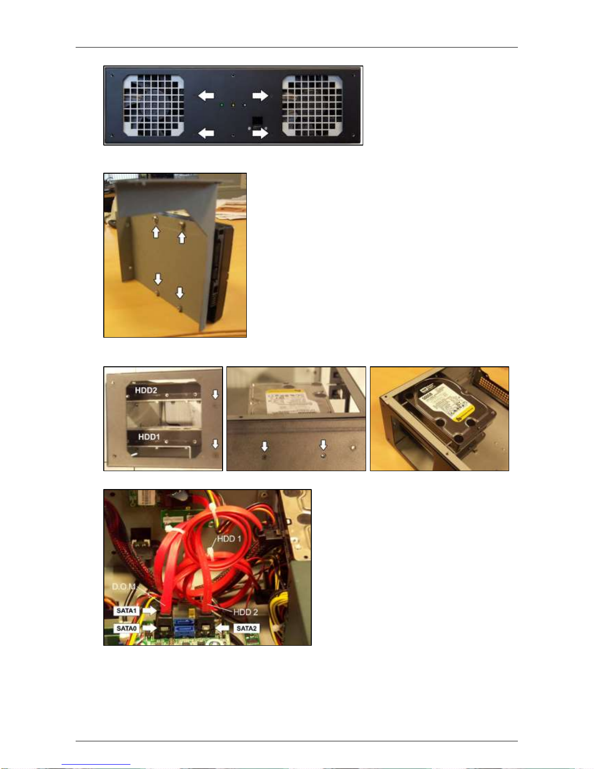
You can now see the mounting holes for the disk bays:
2. Fix the second disk to the support #1729121* with the screws #17434080 or #17434060 and dented
washers M4 #17720050.
3. Fix the support to the casing with 4 screws (#17439080): 2 at the front, and 2 at the left side of the
casing.
4. Connect the disk to the SATA2 connector on the motherboard with the SATA cable (#1652087*).
5. For the power supply to the disk, connect the remaining SATA power connector on the power cable of
disk 1 (not the one on the tail end; that one is reserved for the D.O.M.) to the disk.
6. If you need to add more disks, continue with the next step.
If you do not need to add more disks, continue with step 12.
Page 22
Hardware Installation Manual ADPRO® FastTrace™ 2 Series
22 21790_05
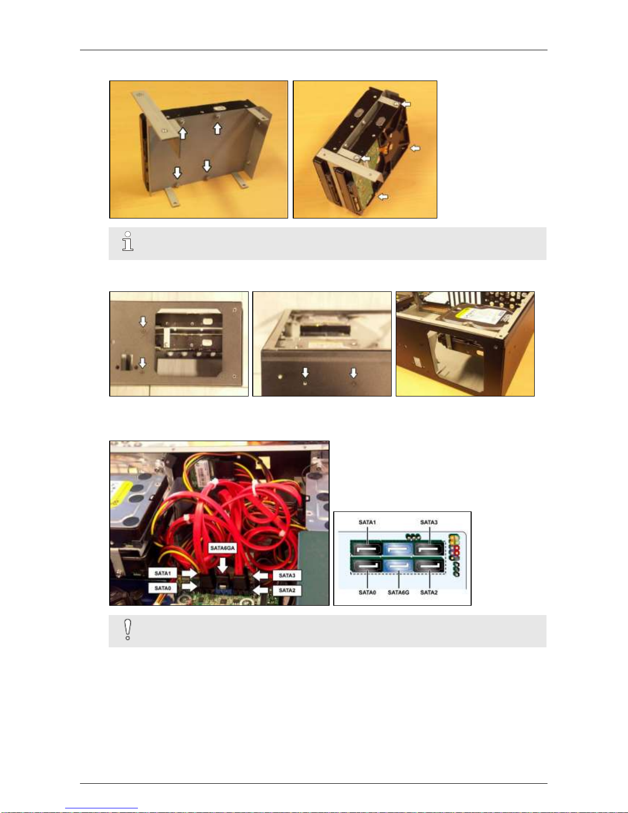
7. Fix the third disk on the top side of the support for disk 3 and 4. If necessary, fix the fourth disk on the
bottom side of the same support.
Note
Make sure to install the disk on the top side of the support first.
8. Fix the support to the casing with 4 screws (#17439080): 2 at the front, and 2 at the right side of the
casing.
9. Connect disk 3 to the SATA3 connector on the motherboard with a SATA cable (#1652087*).
10. If necessary, connect disk 4 to the SATA6GA connector on the motherboard with a SATA cable
(#1652087*).
Caution!
Do not bend the SATA cables too sharply to prevent cable damage.
11. For the power supply to the disk, take an unused SATA power cable and connect it as follows:
- Use the connector that is closest to the power supply for disk 4.
- Use the next connector for disk 3.
Page 23
ADPRO® FastTrace™ 2 Series Hardware Installation Manual
21790_05 23
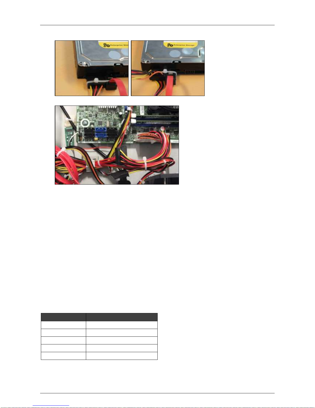
12. If the SATA cables do not have a locking mechanism, use tie-wraps to secure the cables on the
disk(s) in the following way:
13. If there are unused cables left, bundle them with tie-wraps.
14. Fix the front plate (#1701164x or #1701166x) on the base with the screws (#17444080).
Put the cover in place and secure with 10 screws (#17439080).
15. Connect a monitor/screen and keyboard to the FastTrace 2 server. Switch on the power supply and
wait for the boot window to appear.
16. Select XOa Installer and press Enter.
17. The next step depends on the type of hard disk that you are installing:
- If the added hard disk is new, choose Update current system > Manage recording disks and
select the new hard disk in the list. Press Enter. Then choose (using the tab key) Format and use
selected disks. Choose Main Menu and choose Reboot.
- If the added hard disk comes from another server unit, choose Update current system > Mount
all recording disks. Press Enter. Then choose Main Menu and choose Reboot.
The video system now reboots. After rebooting, the new hard disk is ready for use.
3.7 Boot Problems after Adding a HDD with the DH61BE
Motherboard
If you are experiencing boot problems after adding a HDD in a server with a DH61BE motherboard, check if
the SATA cable connections between the HDDs and motherboard are correct. The table below shows the
correct devices and SATA connectors:
Device
SATA Connector
D.O.M.
SATA0
HDD1
SATA1
HDD2
SATA2
HDD3
SATA3
HDD4
SATA6G
Page 24
Hardware Installation Manual ADPRO® FastTrace™ 2 Series
24 21790_05
If the cables connections are different, proceed as follows:
1. Change the cable connections as described in the table.
2. Adjust the boot order in the BIOS. To do so, follow the steps below.
3. Switch off the power supply to the server.
4. Connect a monitor/screen and keyboard to the server.
5. Switch on the power supply and press F2 to enter BIOS mode.
6. Choose Boot, and then choose Boot Drive Order.
The screen displays the current boot order.
7. Put the D.O.M. (= Device on Module; its name is different from the disk names) at the top of the list.
Use the + and – keys to move the D.O.M. in the list. Press Enter to confirm.
8. Choose Exit, and then choose Exit & Save Changes. Choose Yes to confirm.
The server continues booting. If booting is successful, the Xtralis start window appears.
3.8 Adding Hard Disks with a MiTAC PH10LU Motherboard
To add one or more hard disks with a MiTAC PH10LU motherboard, proceed as follows:
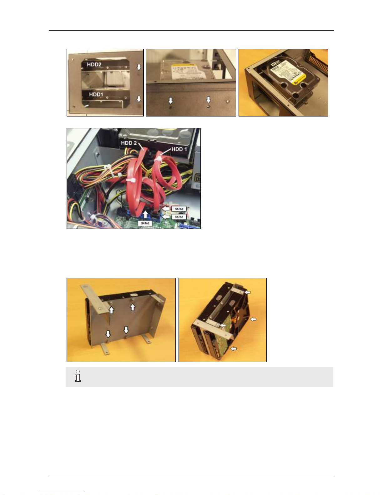
1. Switch off the power supply and remove the lid. Then remove the front plate.
You can now see the mounting holes for the disk bays:
2. Fix the second disk to the support #1729121* with the screws #17434080 or #17434060 and dented
washers M4 #17720050.
Page 25
ADPRO® FastTrace™ 2 Series Hardware Installation Manual
21790_05 25
3. Fix the support to the casing with 4 screws (#17439080): 2 at the front, and 2 at the left side of the
casing.
4. Connect the disk to the SATA2 connector on the motherboard with the SATA cable (#1652087*).
5. For the power supply to the disk, connect the remaining SATA power connector on the power cable of
disk 1 (not the one on the tail end; that one is reserved for the D.O.M.) to the disk.
6. If you need to add more disks, continue with the next step.
If you do not need to add more disks, continue with step 12.
7. Fix the third disk on the top side of the support for disk 3 and 4. If necessary, fix the fourth disk on the
bottom side of the same support.
Note
Make sure to install the disk on the top side of the support first.
Page 26
Hardware Installation Manual ADPRO® FastTrace™ 2 Series
26 21790_05
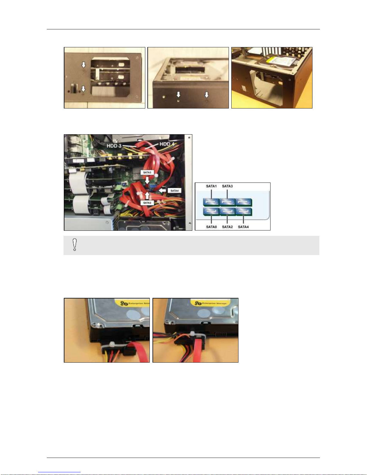
8. Fix the support to the casing with 4 screws (#17439080): 2 at the front, and 2 at the right side of the
casing.
9. Connect disk 3 to the SATA3 connector on the motherboard with a SATA cable (#1652087*).
10. If necessary, connect disk 4 to the SATA4 connector on the motherboard with a SATA cable
(#1652087*).
Caution!
Do not bend the SATA cables too sharply to prevent cable damage.
11. For the power supply to the disk, take an unused SATA power cable and connect it as follows:
- Use the connector that is closest to the power supply for disk 4.
- Use the next connector for disk 3.
12. If the SATA cables do not have a locking mechanism, use tie-wraps to secure the cables on the
disk(s) in the following way:
Page 27
ADPRO® FastTrace™ 2 Series Hardware Installation Manual
21790_05 27
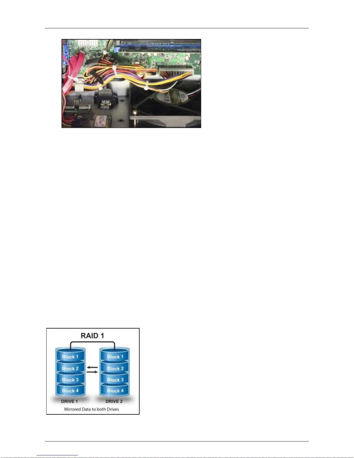
13. If there are unused cables left, bundle them with tie-wraps.
14. Fix the front plate (#1701164x or #1701166x) on the base with the screws (#17444080).
Put the cover in place and secure with 10 screws (#17439080).
15. Connect a monitor/screen and keyboard to the FastTrace 2 server. Switch on the power supply and
wait for the boot window to appear.
16. Select XOa Installer and press Enter.
17. The next step depends on the type of hard disk that you are installing:
- If the added hard disk is new, choose Update current system > Manage recording disks and
select the new hard disk in the list. Press Enter. Then choose (using the tab key) Format and use
selected disks. Choose Main Menu and choose Reboot.
- If the added hard disk comes from another FastTrace 2 unit, choose Update current system >
Mount all recording disks. Press Enter. Then choose Main Menu and choose Reboot.
The video system now reboots. After rebooting, the new hard disk is ready for use.
3.9 RAID 1 Support
From version 2.8.xx onwards, you can activate RAID 1.
3.9.1 About RAID 1
RAID stands for Redundant Array of Independent Disks (originally Redundant Array of Inexpensive Disks).
It is a storage technology that combines multiple disk drive components into a logical unit. Data is distributed
across the drives in one of several ways called RAID levels, depending on the level of redundancy and
performance required. RAID has become an umbrella term for computer data storage schemes that can
divide and replicate data among multiple physical drives, while the operating system can still access the data
as being on one single drive.
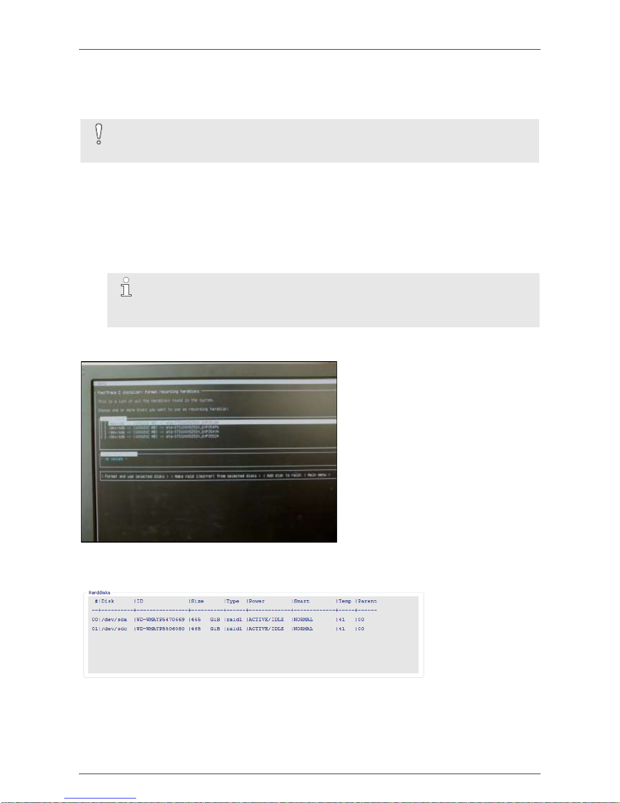
RAID 1 is about mirroring without parity or striping. Data is written identically to two drives, thereby producing
a “mirrored set”: the read request is serviced by either of the two drives containing the requested data,
whichever one has the shortest search time plus rotational latency.
Page 28
Hardware Installation Manual ADPRO® FastTrace™ 2 Series
28 21790_05
3.9.2 Activating RAID 1
RAID 1 requires a minimum of 2 hard disks. The size of the RAID 1 recording combination is the smaller of
the 2 disks installed in your server. If, for example, you have a 1 TB disk and a 2 TB disk, the RAID 1
recording disk has a 1 TB capacity.
Caution!
When you apply RAID 1, the system formats the selected disks and erases the data on the
disks. You will lose all the data on the disks.
To activate RAID 1, proceed as follows:
1. Reboot the server and access the XOa Installer menu.
2. Choose Update current system.
3. Choose Manage recording disks.
4. Use the arrows keys to select the desired hard disk and press Enter to activate the selection. An X
appears in front of the selected hard disk (between the brackets). Select two hard disks, then choose
Make RAID 1 (mirror) from selected disks.
Note
Do not select three or four disks. The third and fourth disk will then be configured as spare
disks within the RAID 1 configuration. If you want to put disk 1 and 2 in RAID 1, and also
disk 3 and 4 in RAID 1, execute this step twice.
5. When mirroring has finished, choose Main menu.
6. Choose Reboot.
You can check which disks are in RAID 1 mode in the XOa client software.
Launch the XOa client software and choose System > Maintenance > Harddisks. At the bottom of the
window you find the Harddisks section. The Type column indicates whether the disk is a RAID 1 disk.
Page 29

ADPRO® FastTrace™ 2 Series Hardware Installation Manual
21790_05 29
4 Fan Speed Selection
Two large fans dissipate the heat. The fans have a switch to select the speed: low, medium, or fast. For most
ambient temperatures, you can set the fan speed to medium. Change the fan speed only for extreme
ambient temperatures.
Note
The most recent units are equipped with new models of fans. These models have no switch to
select the speed. The speed is adjusted automatically.
Page 30
Hardware Installation Manual ADPRO® FastTrace™ 2 Series
30 21790_05
5 Front LED Indicators
5.1 Overview
There are 3 LEDs on the front of the server:
Green LED
Power is on
Yellow LED
Fault
Blue LED
Storage media activity
If the yellow LED lights up, check the status of your server. For more information, see the XOa Client
Software User Manual.
Caution!
When the 3 LEDs are flashing simultaneously, the system is busy updating the recording disks.
In that case, do not turn off power.
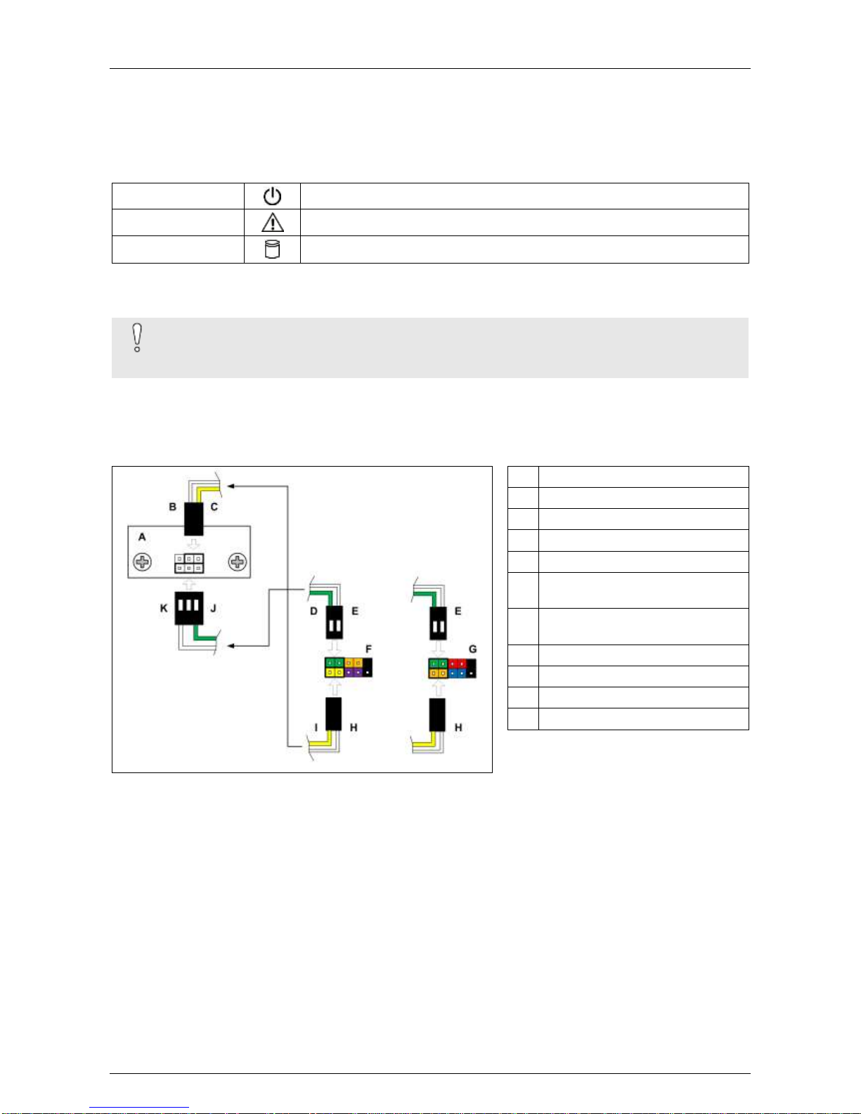
5.2 LED Connections without Main I/O Card
In a system without a Main I/O card, the LED board is connected directly to the motherboard.
A Front LED board
B White
C Yellow
D Green
E White
F Intel motherboard front panel
connector
G MiTAC motherboard front panel
connector
H White
I Yellow
J Green
K White
Page 31
ADPRO® FastTrace™ 2 Series Hardware Installation Manual
21790_05 31
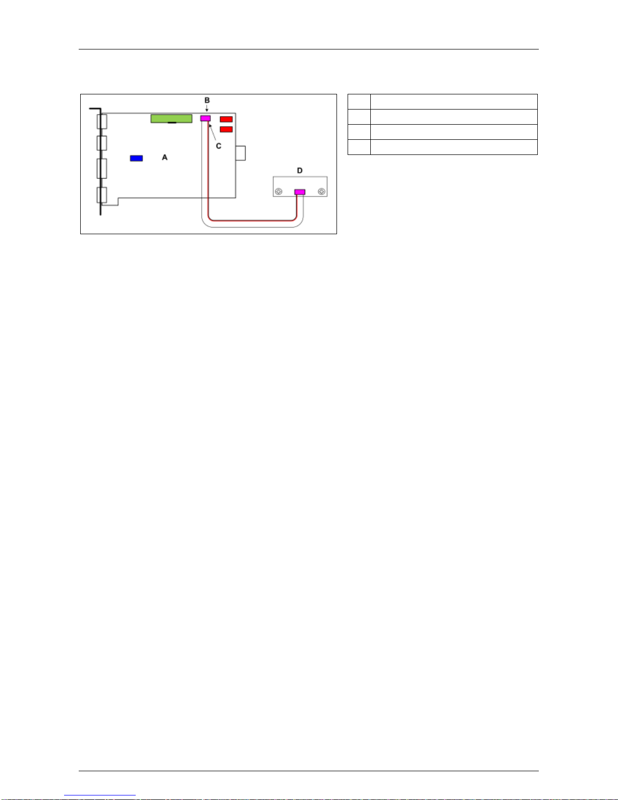
5.3 LED Connections with Main I/O Card
In a system with a Main I/O card, the LED board is connected to the Main I/O card.
A Main I/O card
B 6-pole LED connector
C Red conductor
D Front LED board
Page 32
Hardware Installation Manual ADPRO® FastTrace™ 2 Series
32 21790_05
6 Required Motherboard
6.1 Overview
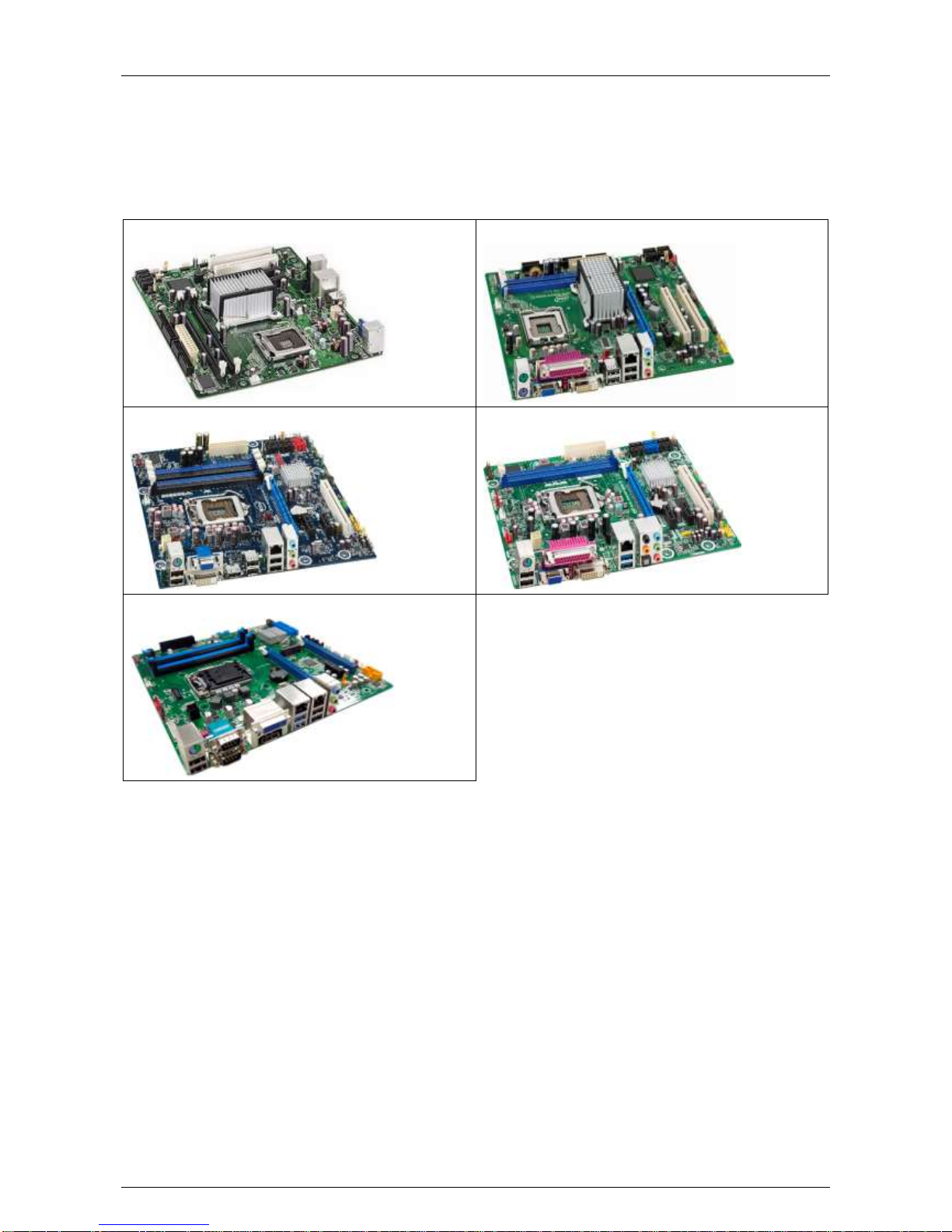
The FastTrace 2 video system only operates with an Intel DG31PR, Intel DG41TY, Intel DH55TC, Intel
DH61BE, or MiTAC PH10LU motherboard.
Intel DG31PR motherboard
Intel DG41TY motherboard
Intel DH55TC motherboard
Intel DH61BE motherboard
MiTAC PH10LU motherboard
6.2 BIOS Settings
6.2.1 Intel DG31PR or Intel DG41TY Motherboard
Choose Main > System Time to set the system time.
Choose Main > System Date to set the system date.
Choose Advanced > Numlock and select the option Off.
Choose Power > After Power Failure and select the option Power-On.
Choose Boot > Boot USB Devices First and select the option Enable.
Choose Exit > Exit & Save Changes and select the option Yes.
All other parameters can be left to the default settings.
6.2.2 Intel DH55TC Motherboard
Choose Main > System Time to set the system time.
Choose Main > System Date to set the system date.
Choose Advanced > Boot > Numlock and select the option Off.
Choose Advanced > Drive Configuration > Smart and select the option Disable.
Choose Advanced > Drive Configuration > Config AHCI and select the option On.
Page 33
ADPRO® FastTrace™ 2 Series Hardware Installation Manual
21790_05 33
Choose Advanced > Event log > Event logging and select the option Disable.
Choose Advanced > Chipset Configuration > HPET and select the option Disable.
Choose Power > After Power Failure and select the option Power-On.
Choose Exit > Exit & Save Changes and select the option Yes.
All other parameters can be left to the default settings.
6.2.3 Intel DH61BE Motherboard
Choose Main > System Time to set the system time.
Choose Main > System Date to set the system date.
Choose Configuration > SATA drives > Smart and select the option Disable.
Choose Configuration > SATA drives > Chipset SATA mode and select the option AHCI.
Choose Configuration > Event log > Event logging and select the option Disable.
If necessary (with newer BIOS versions): Choose Security > Chassis Intrusion and select the option
Disable.
Choose Power > After Power Failure and select the option Power-On.
Choose Boot > Hard drive order and place the DOM CSS HSV40-256M at the top of the list, using the
arrows keys on the keyboard to select the DOM, and the + key to move the selected DOM upwards. Press
Enter.
Choose Exit > Exit & Save Changes and select the option Yes.
All other parameters can be left at the default settings.
Note
With the Intel DH61BE motherboard, you need to reset the BIOS settings every time you
replace or add a hard disk.
6.2.4 MiTAC PH10LU Motherboard
Choose Main > System Time to set the system time.
Choose Main > System Date to set the system date.
Choose Chipset > PCH-IO Configuration > Front Panel Audio and select the option Legacy Front Panel.
Choose Boot > CSM parameters > Launch PXE OPROM policy and select the option Legacy only.
Choose Save & Exit > Exit and Reset and press Enter.
All other parameters can be left at the default settings.
6.3 Replacing the Motherboard
Do not replace the motherboard in the field. If the motherboard needs replacing, send back the server to
your supplier.
6.4 Replacing the Motherboard Battery
It may be necessary to replace the motherboard battery after some time of specific battery faults. For further
instructions, see the technical documentation of the specific motherboard.
Page 34

Hardware Installation Manual ADPRO® FastTrace™ 2 Series
34 21790_05
7 Extension Boards
7.1 Overview
Type
Description
HIPI
PCI Express extension board for 8 IP cameras. (Not compatible with MiTAC PH10LU
motherboard)
See also technical datasheet 19531930 – HIPI card.
Ethernet
For FastTrace 2E only: Ethernet connection for IP camera network up to 32 IP
cameras. An Ethernet card is not required with the MiTAC PH10LU motherboard.
4ch/8ch
DS40xx
PCI extension board for 4 or 8 analogue cameras, including audio inputs per camera.
Note
Use these PCI cards on an Intel DG31PR or Intel DG41TY
motherboard.
4ch/8ch
DS42xx
PCI Express extension board for 4 or 8 or 16 analogue cameras, including audio
inputs per camera.
Note
Use these PCI Express cards on an Intel DH55TC, Intel DH61BE, or
MiTAC PH10LU motherboard.
Main I/O
Main Input Output board: USB extension card, inserted by default in the free slots, or if
necessary in a free PCI or PCI Express connector.
For more information, see technical datasheet 19531920 – Main & Extension I/O
Cards or 19531900 – Main I/O and Extension I/O Next Generation.
Extension I/O
Extension Input Output board: extension board, inserted by default in the free slots, or
if necessary in a free PCI of PCI Express connector and linked to the Main I/O board,
extending the number of inputs and outputs.
For more information, see technical datasheet 19531920 – Main & Extension I/O
Cards or 19531900 – Main I/O and Extension I/O Next Generation.
Page 35
ADPRO® FastTrace™ 2 Series Hardware Installation Manual
21790_05 35
7.2 General Rules
The FastTrace 2 video system offers 6 extension slots:
On Intel DG31PR and Intel DG41TY motherboards: two PCI Express slots, two PCI slots, and two
physical slots.
On Intel DH55TC and Intel DH61BE motherboards: three PCI Express slots, one PCI slot, and two
physical slots.
On the MiTAC PH10LU motherboard: four PCI Express slots, and two physical slots.
You can insert a HIPI card only in a PCI Express slot. HIPI cards are not allowed on the PH10LU
motherboard.
The A/V cards type DS40xx require a PCI slot. The A/V cards type DS42xx require a PCI Express slot. They
also require different types of motherboard, so you cannot mix DS40xx and DS42xx cards.
You can insert Main I/O and Extension I/O cards anywhere, in any free slot. The MIO card is connected to an
internal USB connector, and the EIO card is connected to the MIO card via a flat cable.
7.3 Available Configurations
7.3.1 With Intel DG31PR Motherboard
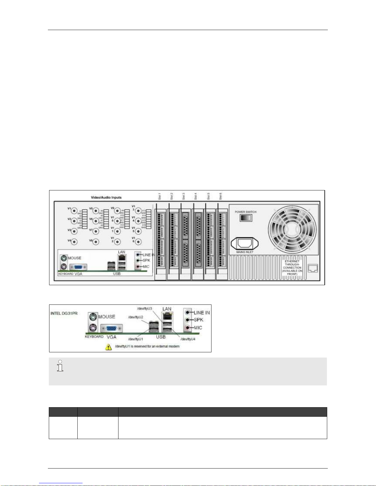
7.3.1.1 Network/Monitor/Keyboard
Note
You must restart the XOa client software after connecting devices to a USB port.
USB input 1 (/dev/ttyU1) is reserved for an external modem.
7.3.1.2 Extension Slots
Slot
Type
Accepts
1
PCI Express
Main I/O
Extension I/O
HIPI (ETH1) for 8 IP cameras
Page 36
Hardware Installation Manual ADPRO® FastTrace™ 2 Series
36 21790_05
Slot
Type
Accepts
2
PCI Express
Main I/O
Extension I/O
HIPI (ETH1) for 8 IP cameras
3
PCI
Main I/O
Extension I/O
A/V with 4 or 8 channels (lowest camera numbers: CAM 1 > 4/8)
4
PCI
Main I/O
Extension I/O
A/V with 4 or 8 channels (highest camera numbers: CAM 5/9 > 8/16)
5 / Extension I/O
6 / Main I/O
7.3.1.3 The Xtralis Configurations
Analogue Cameras (4 – 8 – 12 – 16 Channels)
Slot
Type
Extension Card
1
PCI Express
Extension I/O 2
2
PCI Express
Main I/O 2
3
PCI
A/V 4 channels 1 or A/V 8 channels 2
4
PCI
A/V 8 channels 1
5 / Extension I/O 1
6 / Main I/O 1
IP Cameras (8 or 16 Channels)
Slot
Type
Extension Card
1
PCI Express
HIPI (ETH1)
2
PCI Express
HIPI (ETH2)
3
PCI
Extension I/O 2
4
PCI
Main I/O 2
5 / Extension I/O 1
6 / Main I/O 1
Hybrid (12 Channels)
Slot
Type
Extension Card
1
PCI Express
HIPI (ETH1)
2
PCI Express
Extension I/O 2
3
PCI
A/V 4 channels 1
4
PCI
Main I/O 2
5 / Extension I/O 1
6 / Main I/O 1
Page 37
ADPRO® FastTrace™ 2 Series Hardware Installation Manual
21790_05 37
Hybrid (16 Channels)
Slot
Type
Extension Card
1
PCI Express
HIPI (ETH1)
2
PCI Express
Extension I/O 2
3
PCI
Main I/O 2
4
PCI
A/V 8 channels 1
5 / Extension I/O 1
6 / Main I/O 1
7.3.2 With Intel DG41TY Motherboard
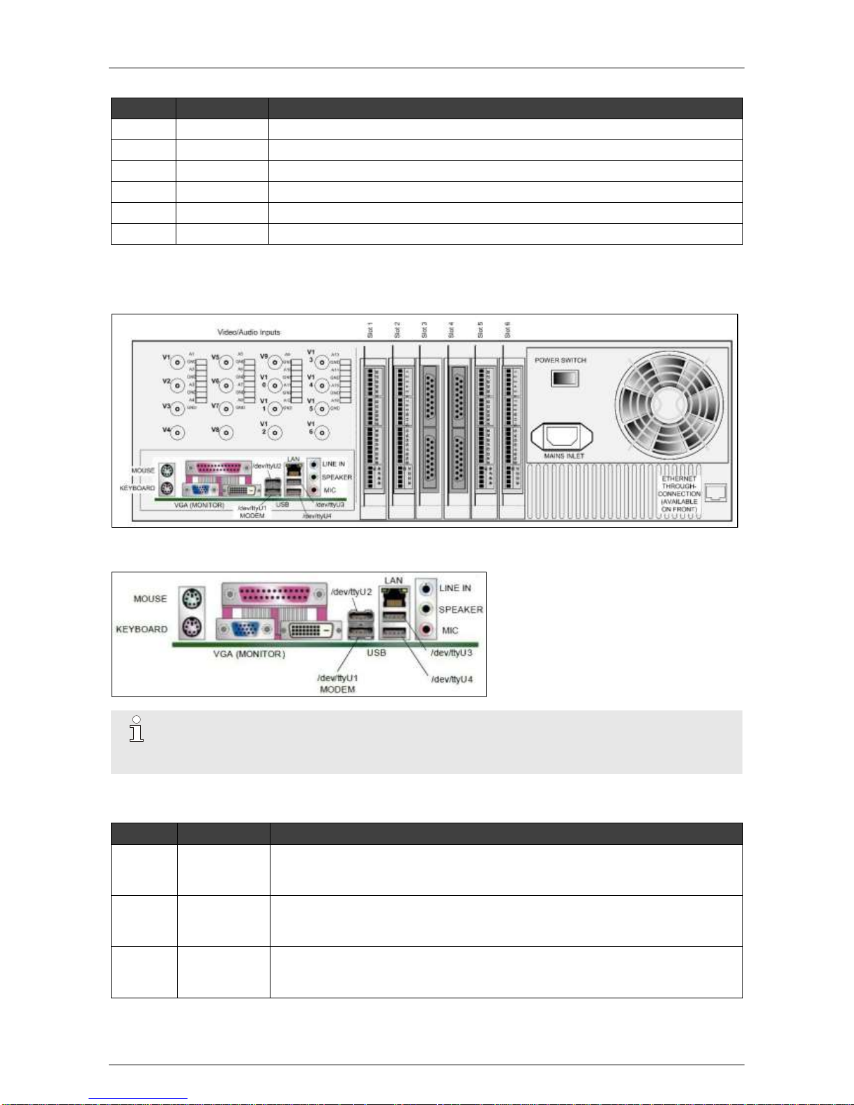
7.3.2.1 Network/Monitor/Keyboard
Note
You must restart the XOa client software after connecting devices to a USB port.
USB input 1 (/dev/ttyU1) is reserved for an external modem.
7.3.2.2 Extension Slots
Slot
Type
Accepts
1
PCI Express
Main I/O
Extension I/O
HIPI (ETH1) for 8 IP cameras
2
PCI Express
Main I/O
Extension I/O
HIPI (ETH1) for 8 IP cameras
3
PCI
Main I/O
Extension I/O
A/V with 4 or 8 channels (lowest camera numbers: CAM 1 > 4/8)
Page 38
Hardware Installation Manual ADPRO® FastTrace™ 2 Series
38 21790_05
Slot
Type
Accepts
4
PCI
Main I/O
Extension I/O
A/V with 4 or 8 channels (highest camera numbers: CAM 5/9 > 8/16)
5 / Extension I/O
6 / Main I/O
7.3.2.3 The Xtralis Configurations
Analogue Cameras (4 – 8 – 12 – 16 Channels)
Slot
Type
Extension Card
1
PCI Express
Extension I/O 2
2
PCI Express
Main I/O 2
3
PCI
A/V 4 channels 1 or A/V 8 channels 2
4
PCI
A/V 8 channels 1
5 / Extension I/O 1
6 / Main I/O 1
IP Cameras (8 or 16 Channels)
Slot
Type
Extension Card
1
PCI Express
HIPI (ETH1)
2
PCI Express
HIPI (ETH2)
3
PCI
Extension I/O 2
4
PCI
Main I/O 2
5 / Extension I/O 1
6 / Main I/O 1
Hybrid (12 Channels)
Slot
Type
Extension Card
1
PCI Express
HIPI (ETH1)
2
PCI Express
Extension I/O 2
3
PCI
A/V 4 channels 1
4
PCI
Main I/O 2
5 / Extension I/O 1
6 / Main I/O 1
Hybrid (16 Channels)
Slot
Type
Extension Card
1
PCI Express
HIPI (ETH1)
2
PCI Express
Extension I/O 2
3
PCI
A/V 8 channels 1
4
PCI
Main I/O 2
5 / Extension I/O 1
6 / Main I/O 1
Page 39
ADPRO® FastTrace™ 2 Series Hardware Installation Manual
21790_05 39
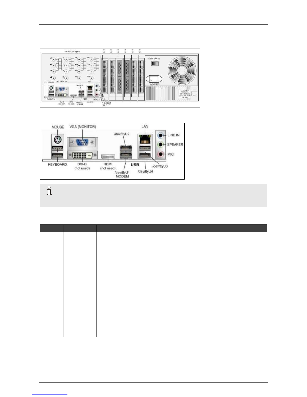
7.3.3 With Intel DH55TC Motherboard
7.3.3.1 Network/Monitor/Keyboard
Note
You must restart the XOa client software after connecting devices to a USB port.
USB input 1 (/dev/ttyU1) is reserved for an external modem.
7.3.3.2 Extension Slots
Slot
Type
Accepts
1
PCI Express
Main I/O
Extension I/O
HIPI (ETH1) for 8 IP cameras
A/V with 4 or 8 channels
2
PCI Express
Main I/O
Extension I/O
HIPI (ETH1) for 8 IP cameras
A/V with 4 or 8 channels
3
PCI Express
Main I/O
Extension I/O
A/V with 4 or 8 or 16 channels
4
PCI
Main I/O
Extension I/O
5 / Main I/O
Extension I/O
6 / Main I/O
Extension I/O
When using A/V cards of equal A/V inputs, attribute the lowest camera numbers to the A/V card that is in or
closest to slot 1.
When combining a 4CH and an 8CH A/V card, attribute the lowest camera numbers to the 4CH A/V card.
Page 40
Hardware Installation Manual ADPRO® FastTrace™ 2 Series
40 21790_05
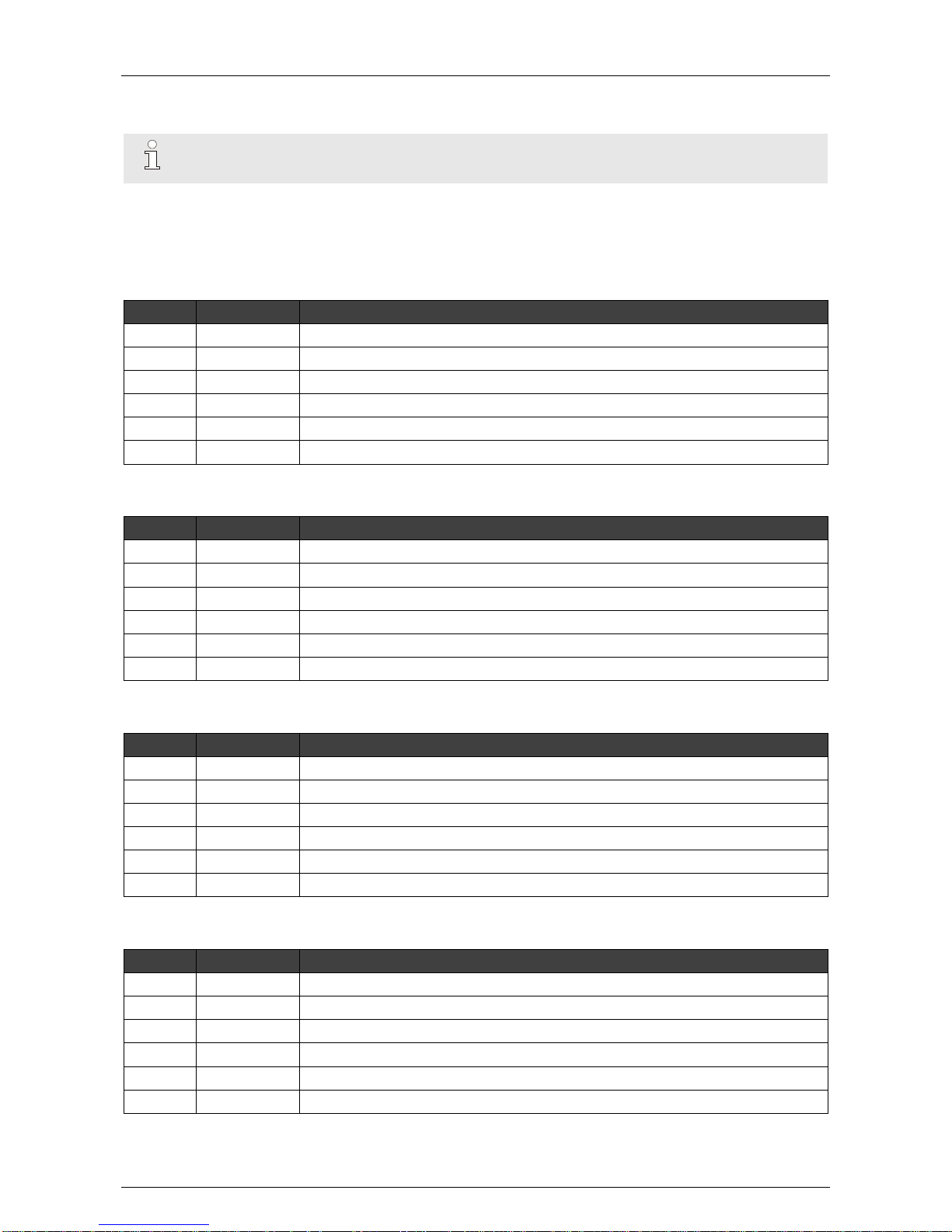
Example: camera numbers 1–4 allocated to the 4CH A/V card, and numbers 5–12 allocated to the 8CH A/V
card.
Note
Only the A/V cards type DS42xx are allowed on the Intel DH55TC motherboard.
7.3.3.3 The Xtralis Configurations
Analogue Cameras (4 Channels)
Slot
Type
Extension Card
1
PCI Express
Extension I/O 2
2
PCI Express
A/V 4 channels 1 (DS42xx)
3
PCI Express
4
PCI
Main I/O 2
5 / Extension I/O 1
6 / Main I/O 1
Analogue Cameras (8 Channels)
Slot
Type
Extension Card
1
PCI Express
Extension I/O 2
2
PCI Express
A/V 8 channels 1 (DS42xx)
3
PCI Express
4 PCI
Main I/O 2
5 / Extension I/O 1
6 / Main I/O 1
Analogue Cameras (12 Channels)
Slot
Type
Extension Card
1
PCI Express
Extension I/O 2
2
PCI Express
A/V 4 channels 1 (DS42xx)
3
PCI Express
A/V 8 channels 1 (DS42xx)
4
PCI
Main I/O 2
5 / Extension I/O 1
6 / Main I/O 1
Analogue Cameras (16 Channels)
Slot
Type
Extension Card
1
PCI Express
Extension I/O 2
2
PCI Express
3 PCI Express
A/V 16 channels 1 (DS42xx)
4
PCI
Main I/O 2
5 / Extension I/O 1
6 / Main I/O 1
Page 41
ADPRO® FastTrace™ 2 Series Hardware Installation Manual
21790_05 41
IP Cameras (8 or 16 Channels)
Slot
Type
Extension Card
1
PCI Express
HIPI (ETH1)
2
PCI Express
HIPI (ETH2)
3
PCI Express
Extension I/O 2
4
PCI
Main I/O 2
5 / Extension I/O 1
6 / Main I/O 1
Hybrid (12 Channels)
Slot
Type
Extension Card
1
PCI Express
HIPI (ETH1)
2
PCI Express
Extension I/O 2
3
PCI Express
A/V 4 channels 1
4
PCI
Main I/O 2
5 / Extension I/O 1
6 / Main I/O 1
Hybrid (16 Channels)
Slot
Type
Extension Card
1
PCI Express
HIPI (ETH1)
2
PCI Express
Extension I/O 2
3
PCI Express
A/V 8 channels 1
4
PCI
Main I/O 2
5 / Extension I/O 1
6 / Main I/O 1
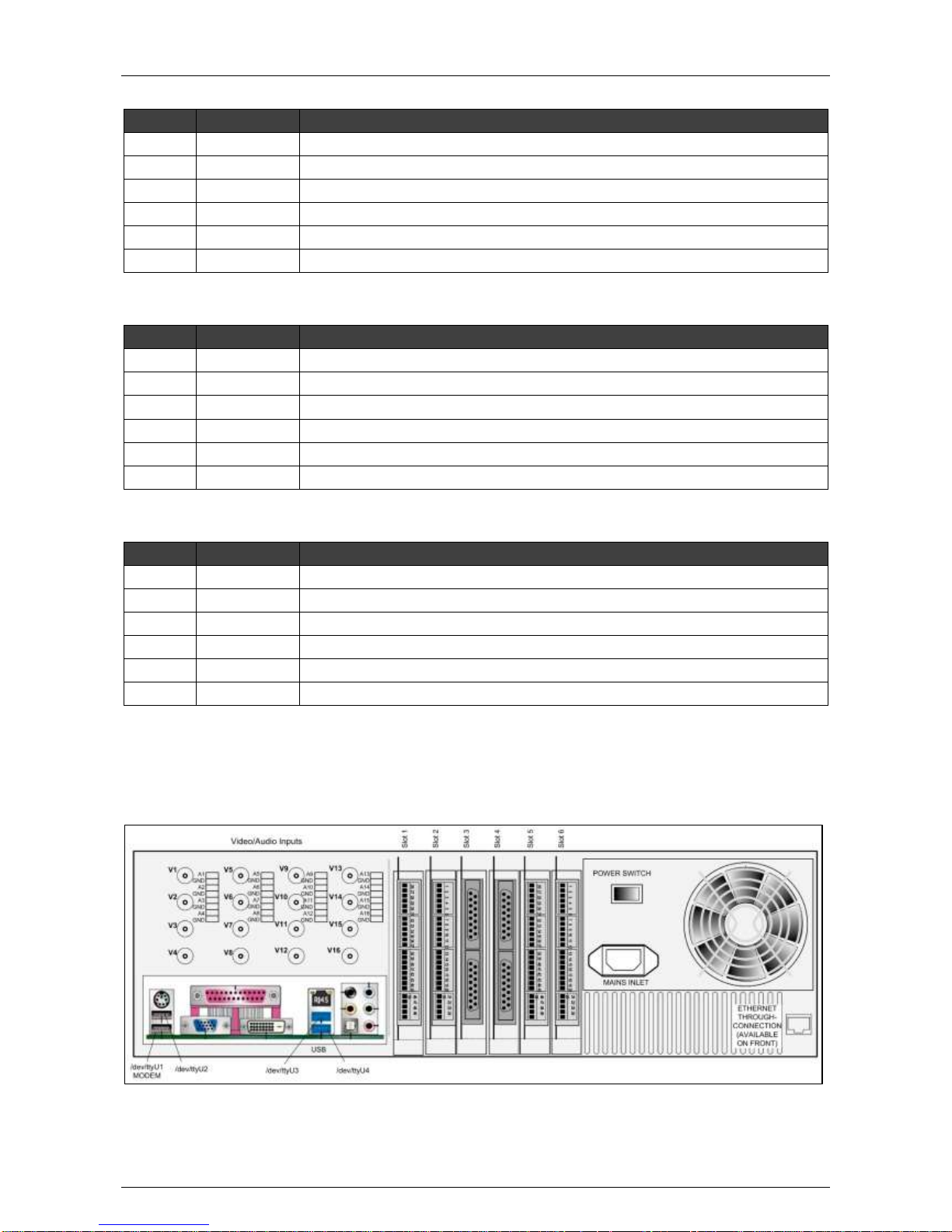
A sticker below each slot, visible from the back of the appliance, indicates which card has been installed at
that position.
7.3.4 With Intel DH61BE Motherboard
Page 42
Hardware Installation Manual ADPRO® FastTrace™ 2 Series
42 21790_05
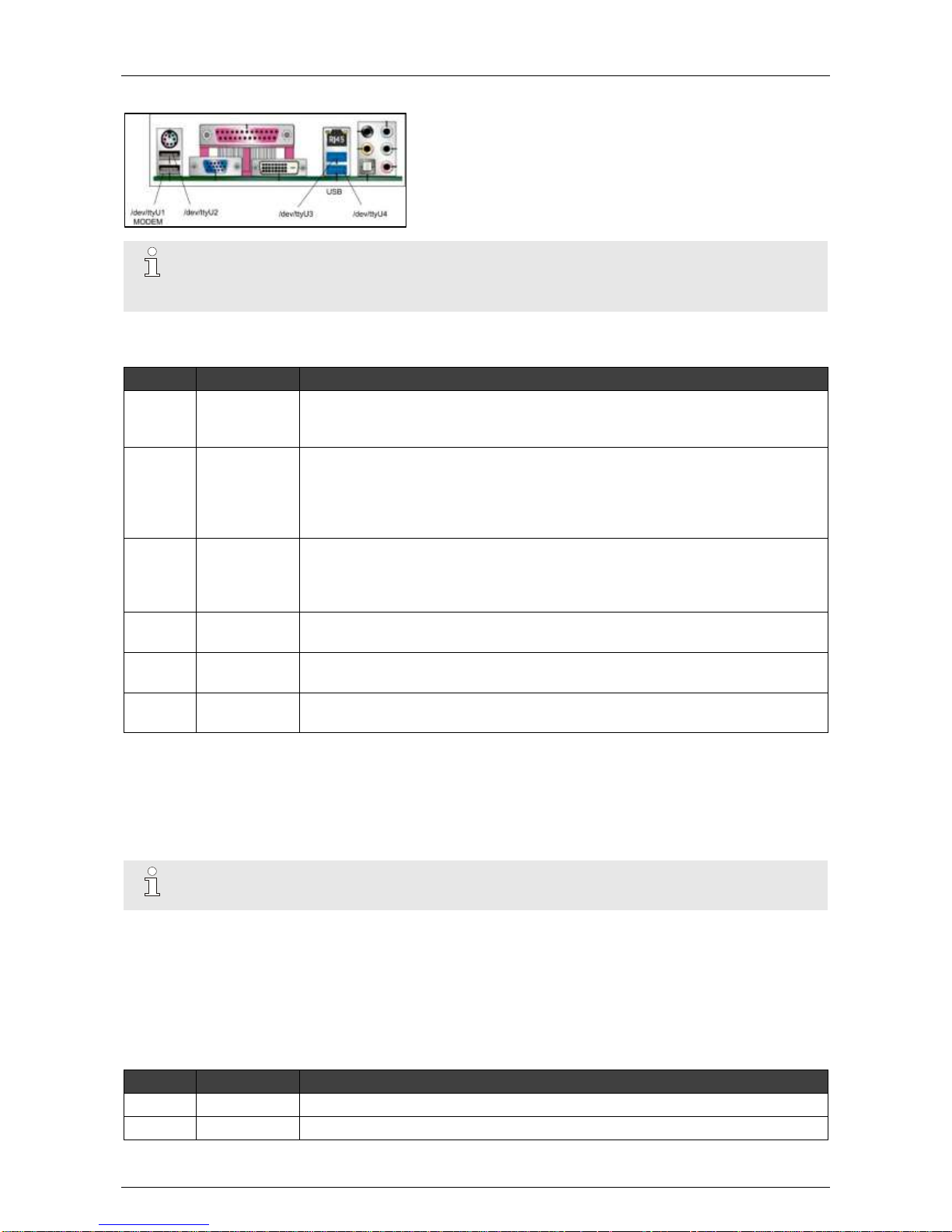
7.3.4.1 Network/Monitor/Keyboard
Note
You must restart the XOa client software after connecting devices to a USB port.
USB input 1 (/dev/ttyU1) is reserved for an external modem.
7.3.4.2 Extension Slots
Slot
Type
Accepts
1
PCI Express
Main I/O
Extension I/O
A/V with 4 or 8 or 16 channels
2
PCI Express
Main I/O
Extension I/O
HIPI (ETH1) for 8 IP cameras
Ethernet Card
A/V with 4 or 8 channels
3
PCI Express
Main I/O
Extension I/O
HIPI (ETH2) for 8 IP cameras
A/V with 4 or 8 channels
4
PCI
Main I/O
Extension I/O
5 / Main I/O
Extension I/O
6 / Main I/O
Extension I/O
When using A/V cards of equal A/V inputs, attribute the lowest camera numbers to the A/V card that is in or
closest to slot 1.
When combining a 4CH and an 8CH A/V card, attribute the lowest camera numbers to the 4CH A/V card.
Example: camera numbers 1–4 allocated to the 4CH A/V card, and numbers 5–12 allocated to the 8CH A/V
card.
Note
Only the A/V cards type DS42xx are allowed on the Intel DH61BE motherboard.
7.3.4.3 The Xtralis Configurations for FastTrace 2 Units
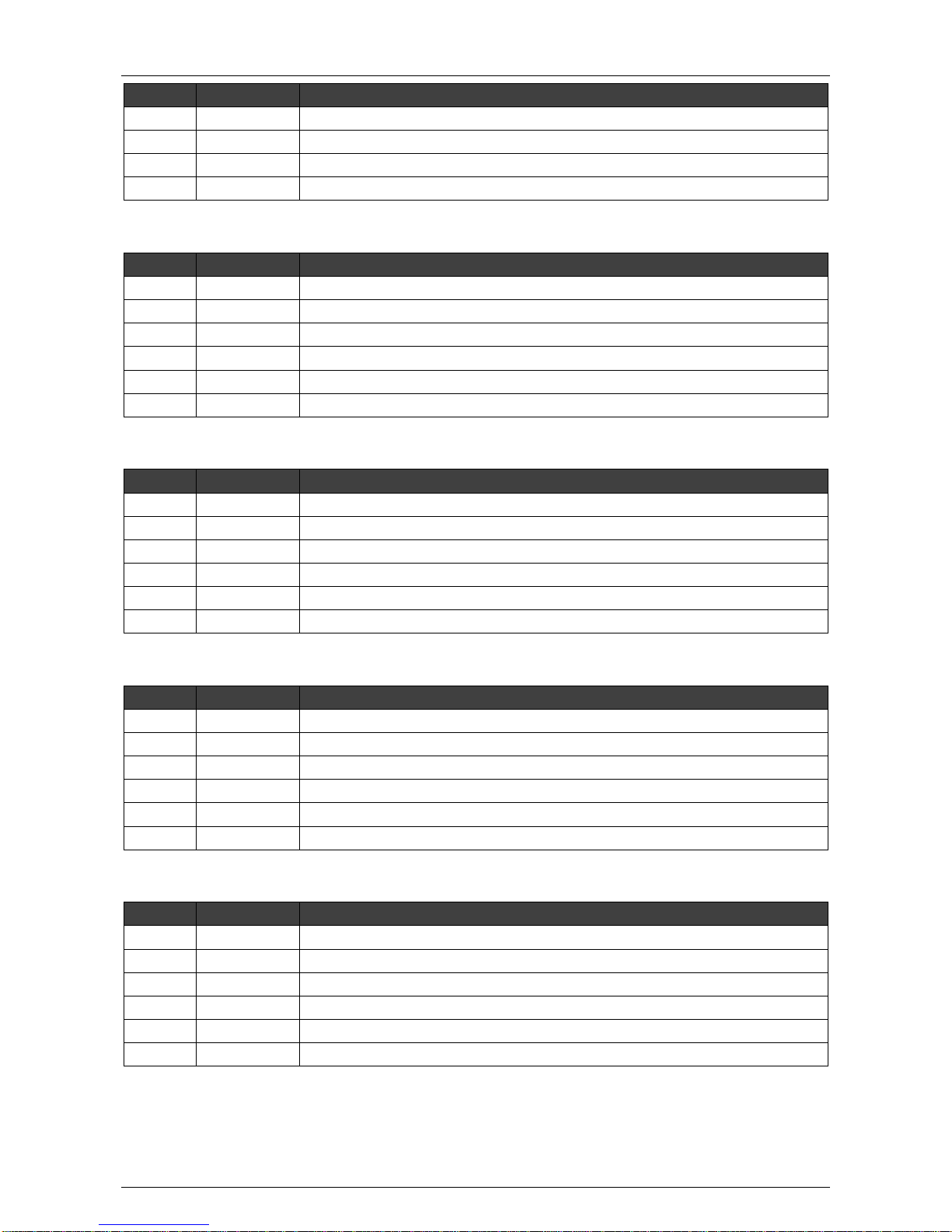
From December 2013 onwards the FastTrace 2 will only be available as an analogue-only unit. Existing
FastTrace 2 IP and/or Hybrid units can no longer be expanded.
Analogue Cameras (4 Channels)
Slot
Type
Extension Card
1
PCI Express
A/V 4 channels 1 (DS42xx)
2
PCI Express
Page 43
ADPRO® FastTrace™ 2 Series Hardware Installation Manual
21790_05 43
Slot
Type
Extension Card
3
PCI Express
Extension I/O 2
4
PCI
Main I/O 2
5 / Extension I/O 1
6 / Main I/O 1
Analogue Cameras (8 Channels)
Slot
Type
Extension Card
1
PCI Express
A/V 8 channels 1 (DS42xx)
2
PCI Express
3 PCI Express
Extension I/O 2
4
PCI
Main I/O 2
5 / Extension I/O 1
6 / Main I/O 1
Analogue Cameras (12 Channels)
Slot
Type
Extension Card
1
PCI Express
A/V 4 channels 1 (DS42xx)
2
PCI Express
A/V 8 channels 1 (DS42xx)
3
PCI Express
Extension I/O 2
4
PCI
Main I/O 2
5 / Extension I/O 1
6 / Main I/O 1
Analogue Cameras (16 Channels)
Slot
Type
Extension Card
1
PCI Express
A/V 16 channels 1 (DS42xx)
2
PCI Express
3
PCI Express
Extension I/O 2
4
PCI
Main I/O 2
5 / Extension I/O 1
6 / Main I/O 1
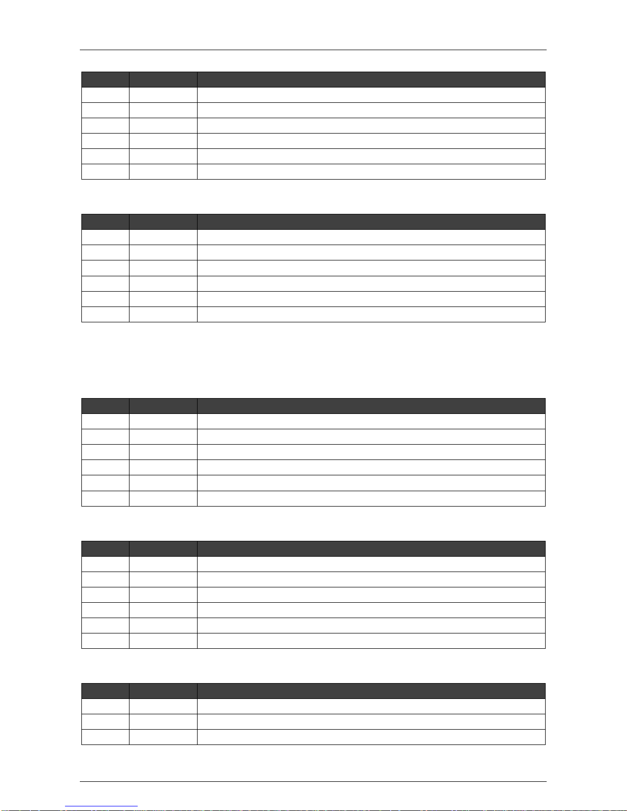
IP Cameras (8 or 16 Channels with 1 or 2 HIPI Cards)
Slot
Type
Extension Card
1
PCI Express
Extension I/O 2
2
PCI Express
HIPI (ETH1)
3
PCI Express
HIPI (ETH2) (only when 16 channels)
4
PCI
Main I/O 2
5 / Extension I/O 1
6 / Main I/O 1
Page 44
Hardware Installation Manual ADPRO® FastTrace™ 2 Series
44 21790_05
Hybrid (12 Channels with 1 HIPI Card)
Slot
Type
Extension Card
1
PCI Express
A/V 4 channels 1
2
PCI Express
HIPI (ETH1)
3
PCI Express
Extension I/O 2
4
PCI
Main I/O 2
5 / Extension I/O 1
6 / Main I/O 1
Hybrid (16 Channels with 1 HIPI Card)
Slot
Type
Extension Card
1
PCI Express
A/V 8 channels 1
2
PCI Express
HIPI (ETH1)
3
PCI Express
Extension I/O 2
4
PCI
Main I/O 2
5 / Extension I/O 1
6 / Main I/O 1
7.3.4.4 The Xtralis Configurations for FastTrace 2E Units
Analogue Cameras (4 Channels)
Slot
Type
Extension Card
1
PCI Express
A/V 4 channels 1 (DS42xx)
2
PCI Express
Ethernet Card
3
PCI Express
Extension I/O 2
4
PCI
Main I/O 2
5 / Extension I/O 1
6 / Main I/O 1
Analogue Cameras (8 Channels)
Slot
Type
Extension Card
1
PCI Express
A/V 8 channels 1 (DS42xx)
2
PCI Express
Ethernet Card
3
PCI Express
Extension I/O 2
4
PCI
Main I/O 2
5 / Extension I/O 1
6 / Main I/O 1
Analogue Cameras (12 Channels)
Slot
Type
Extension Card
1
PCI Express
A/V 4 channels 1 (DS42xx)
2
PCI Express
A/V 8 channels 1 (DS42xx)
3
PCI Express
Ethernet card
Page 45
ADPRO® FastTrace™ 2 Series Hardware Installation Manual
21790_05 45
Slot
Type
Extension Card
4
PCI
Main I/O 2
5 / Extension I/O 1
6 / Main I/O 1
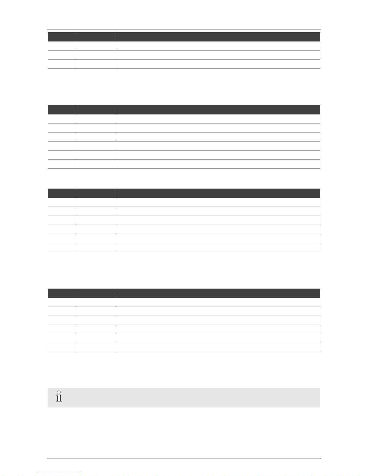
If you want to use a second Extension I/O card, you have to replace either the Ethernet card or one of the
analogue video cards in the PCI Express slots.
Analogue Cameras (16 Channels)
Slot
Type
Extension Card
1
PCI Express
A/V 16 channels 1 (DS42xx)
2
PCI Express
Ethernet Card
3
PCI Express
Extension I/O 2
4
PCI
Main I/O 2
5 / Extension I/O 1
6 / Main I/O 1
Analogue Cameras (20 Channels)
Slot
Type
Extension Card
1
PCI Express
A/V 16 channels 1 (DS42xx)
2
PCI Express
A/V 4 channels 1 (DS42xx)
3
PCI Express
Ethernet card
4
PCI
Main I/O 2
5 / Extension I/O 1
6 / Main I/O 1
If you want to use a second Extension I/O card, you have to replace either the Ethernet card or one of the
analogue video cards in the PCI Express slots.
IP Cameras (Up to 32 Channels* with 1 Ethernet Card)
Slot
Type
Extension Card
1
PCI Express
2
PCI Express
Ethernet Card
3
PCI Express
Extension I/O 2
4
PCI
Main I/O 2
5 / Extension I/O 1
6 / Main I/O 1
(*) You can purchase IP camera licenses individually or in sets of 4. Depending on the license(s) you have
purchased, you will have 1-32 video channels available. The full 32 channels are only available on
FastTrace 2E models with XOa firmware installed, an Intel DH61BE or MiTAC PH10LU motherboard, and
4 GB RAM or more. On any other model, maximum 16 IP channels are available.
Note
You can use the Ethernet card only on FastTrace 2E units.
Page 46
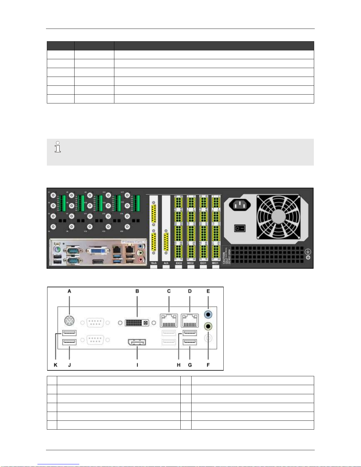
Hardware Installation Manual ADPRO® FastTrace™ 2 Series
46 21790_05
Hybrid (up to 32 Channels* with 1 Ethernet Card)
Slot
Type
Extension Card
1
PCI Express
A/V 4 or A/V 8 or A/V 16 channels
2
PCI Express
Ethernet Card
3
PCI Express
Extension I/O 2
4
PCI
Main I/O 2
5 / Extension I/O 1
6 / Main I/O 1
(*) You can purchase IP camera licenses individually or in sets of 4. Depending on the license(s) you have
purchased, you will have 1-32 video channels available. The full 32 channels are only available on
FastTrace 2E models with XOa firmware installed, an Intel DH61BE or MiTAC PH10LU motherboard, and
4 GB RAM or more. On any other model, maximum 16 IP channels are available.
Note
You can use the Ethernet card only on FastTrace 2E units.
You cannot use HIPI cards on FastTrace 2E units.
7.3.5 With MiTAC PH10LU Motherboard
7.3.5.1 Network/Monitor/Modem
A
PS/2 (keyboard)
G
dev/ttyU4 (USB)
B
DVI-I (monitor)
H
dev/ttyU3 (USB)
C
ETH0: network for FastTrace 2 device
I
DisplayPort (monitor)
D
ETH1: IP gateway, network for IP cameras…
J
dev/ttyU1 (USB, modem)
E
Audio line in
K
dev/ttyU2 (USB)
F
Audio line out
Page 47
ADPRO® FastTrace™ 2 Series Hardware Installation Manual
21790_05 47
7.3.5.2 The Xtralis Configurations
The table below shows the possible configurations with a MiTAC PH10LU motherboard:
Slot
Type
1
PCI
Express
2
PCI
Express
3
PCI
Express
4
PCI
Express
5
–
6
–
Analogue 4 ch
A/V 4 ch
–
EIO 2
MIO 2
EIO 1
MIO 1
Analogue 8 ch
A/V 8 ch
–
Analogue 12 ch
A/V 4 ch
A/V 8 ch
Analogue 16 ch
A/V 16 ch
–
Analogue 20 ch
A/V 16 ch
A/V 4 ch
Digital 1–32 ch
–
–
Hybrid 32 ch (4 analogue)
A/V 4 ch
–
Hybrid 32 ch (8 analogue)
A/V 8 ch
–
Hybrid 32 ch (12 analogue)
A/V 4 ch
A/V 8 ch
Hybrid 32 ch (16 analogue)
A/V 16 ch
–
Analogue x ch = unit with analogue cameras only, x = the number of channels
Digital x ch = unit with IP cameras only, x = the number of channels
Hybrid x ch (y analogue) = unit with analogue and IP cameras, x = the total number of channels, y = the
number of analogue channels
A/V x ch = analogue video card, x = the number of channels
Page 48
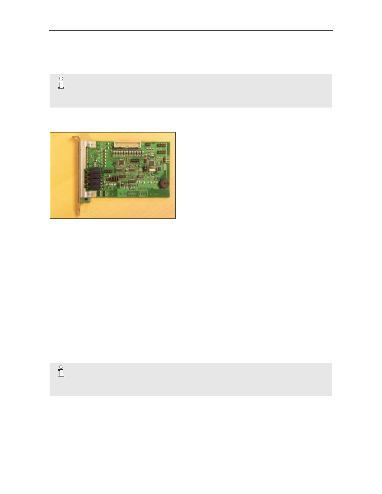
Hardware Installation Manual ADPRO® FastTrace™ 2 Series
48 21790_05
8 Main and Extension I/O Cards
8.1 Features
Note
With the FastTrace 2E Series, Xtralis introduced the Next Generation I/O cards. If you are using
Next Generation cards with your FastTrace 2E unit, see Main and Extension I/O Cards Next
Generation on page 57.
The Main I/O (MIO) and Extension I/O (EIO) cards are internal I/O cards, to be fitted inside the ADPRO
FastTrace 2 system. They are also called OTB (on-the-board) cards.
These I/O cards offer:
8 tamper-protected inputs and 4 relay outputs (rated 14 VDC @ 1 A) on the Main I/O card
12 tamper-protected inputs and 4 relay outputs on the Extension I/O card
driver for PTZ cameras (half/full duplex RS-485) or audio module/VM22A audio switcher (selected by
jumpers on the card)
driver for front LED indicators on FastTrace 2 model
auto-detected cards on FastTrace 2 system
8.2 Possible Configurations
You can configure maximum 2 sets of I/O cards on the FastTrace 2:
Main I/O only
Main I/O + Extension I/O
2 x Main I/O + Extension I/O
2 x Main I/O + 2 x Extension I/O
Note
With an ENTRY system license you can install only 1 Main I/O card. Multiple Main I/O cards are
not supported. Also, an ENTRY system does not support Extension I/O cards. This is for
instance the case with the ADPRO FastTrace 2 Lite.
Page 49
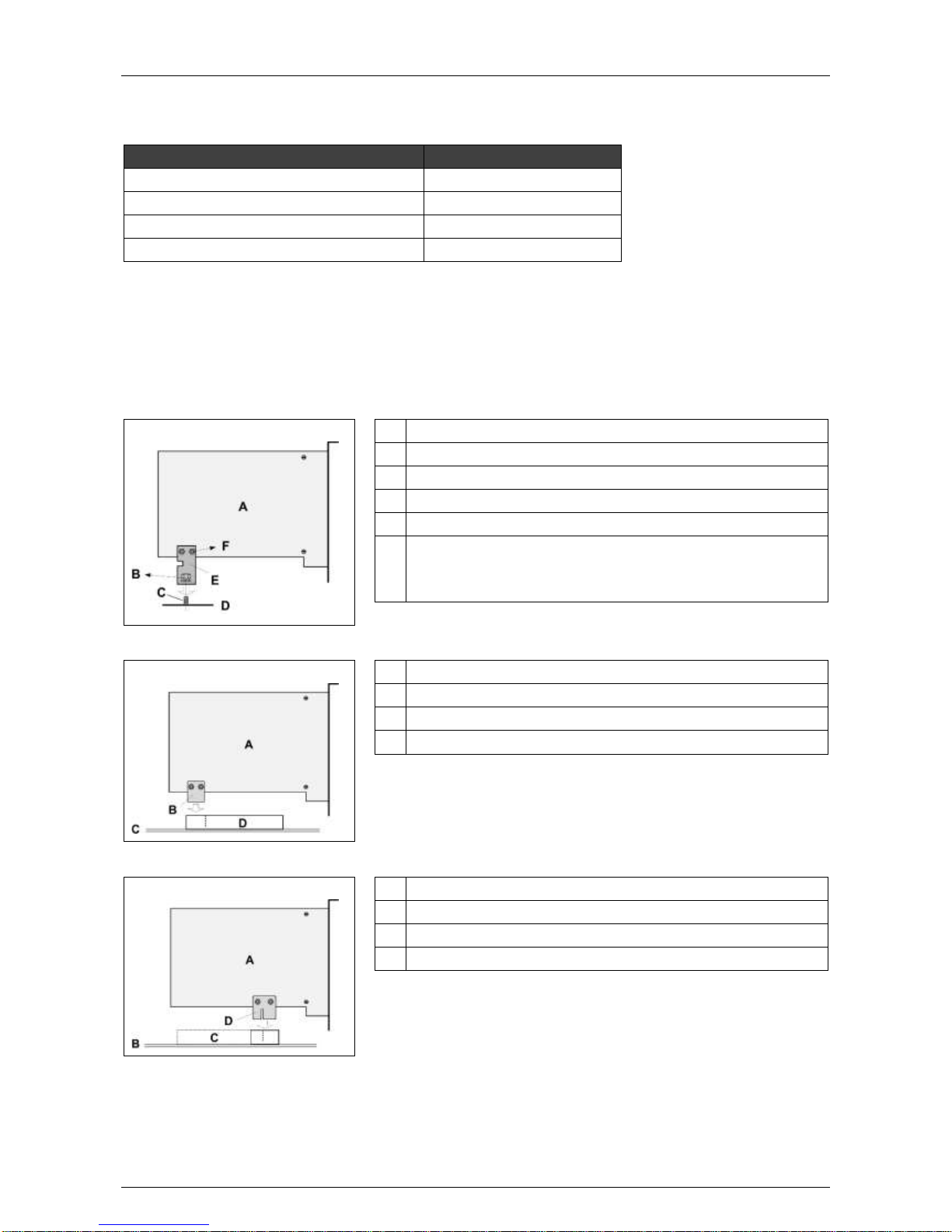
ADPRO® FastTrace™ 2 Series Hardware Installation Manual
21790_05 49
8.3 Ordering Information
Use these reference numbers to place your order with Xtralis:
Item
Reference Number
Main I/O card
39544070
Main I/O card plus mounting set
39544000
Extension I/O card
39544080
Extension I/O card plus mounting set
39544010
8.4 Physical Position
Insert the first set of I/O cards in the two furthermost slots (= nearest to the power supply). Use the L-shaped
brackets to fix the cards to the chassis. Insert the Main I/O card in the furthermost slot (= slot 6).
Insert the second set in the PCI or PCI Express slots on the motherboard using the included PCI or PCI
Express Inserters. Depending on the type of motherboard, you need either a PCI or PCI Express Inserter.
Mounting on chassis:
A I/O card, bottom side
B Locknut (#17439010)
C M3 stud
D Chassis
E L-shaped metal bracket (#17291141) – on top side
F Screw M2.5 (#17420060)
Nut M2.5 (#17429000)
Dented washer M2.5 (#17720090)
PCI connector:
A I/O card, bottom side
B PCI inserter (#17291100)
C Motherboard
D PCI connector
PCI Express connector:
A I/O card, bottom side
B Motherboard
C PCI Express connector
D PCI Express inserter (#17291110)
Page 50
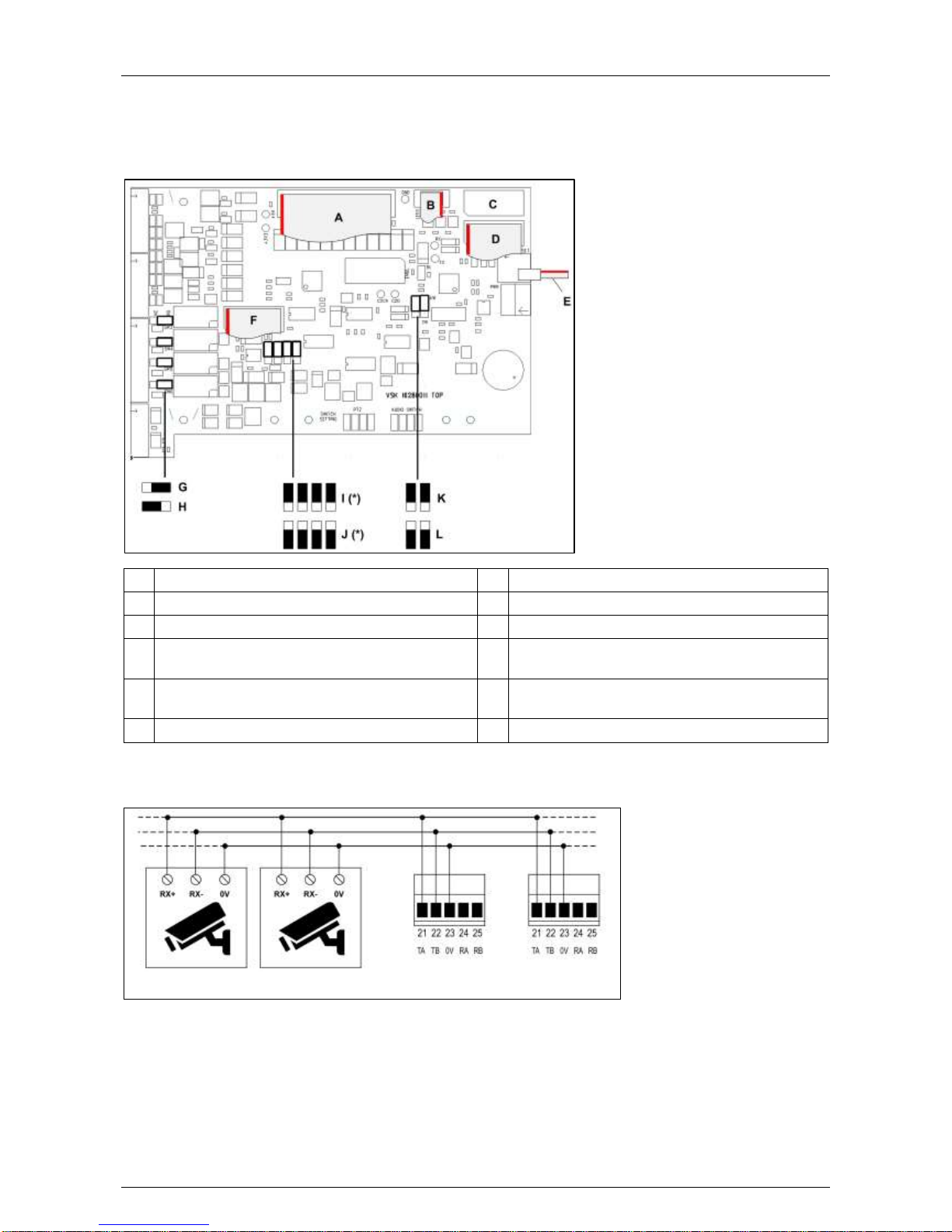
Hardware Installation Manual ADPRO® FastTrace™ 2 Series
50 21790_05
8.5 Settings on the Main I/O Card
If you are connecting PTZ cameras from the same RS-485 bus to multiple FastTrace 2 servers, set the
RS-485 PTZ jumper on the Main I/O card to the 2-wire (PTZ) position.
RS-485 cable length: max. 1200 m.
A
To Extension I/O card (#21760300)
G
Jumper setting: normally open relay contact
B
To front LEDs (#21760101)
H
Jumper setting: normally closed relay contact
C
USB port; to second Main I/O card
I
Jumper setting: PTZ output (*)
D
To nearest USB port on motherboard
(#16540260)
J
Jumper setting: VM22A output (*)
E
Reset signal from motherboard (#21760401)
K
RS-485 PTZ jumper: 4-wire setting (default
setting)
F
To AUDIO on motherboard (#16540280)
L
RS-485 PTZ jumper: 2-wire setting
(*) PTZ/VM22A:
On 1st Main I/O: addressed as /dev/ttyU6.
On 2nd Main I/O: addressed as /dev/ttyU8.
PTZ cameras
Main I/O cards
8.6 Installation
To install the Main I/O card, proceed as follows:
1. Switch off the power supply, and remove the lid from the server.
2. Remove any superfluous blind brackets.
Page 51
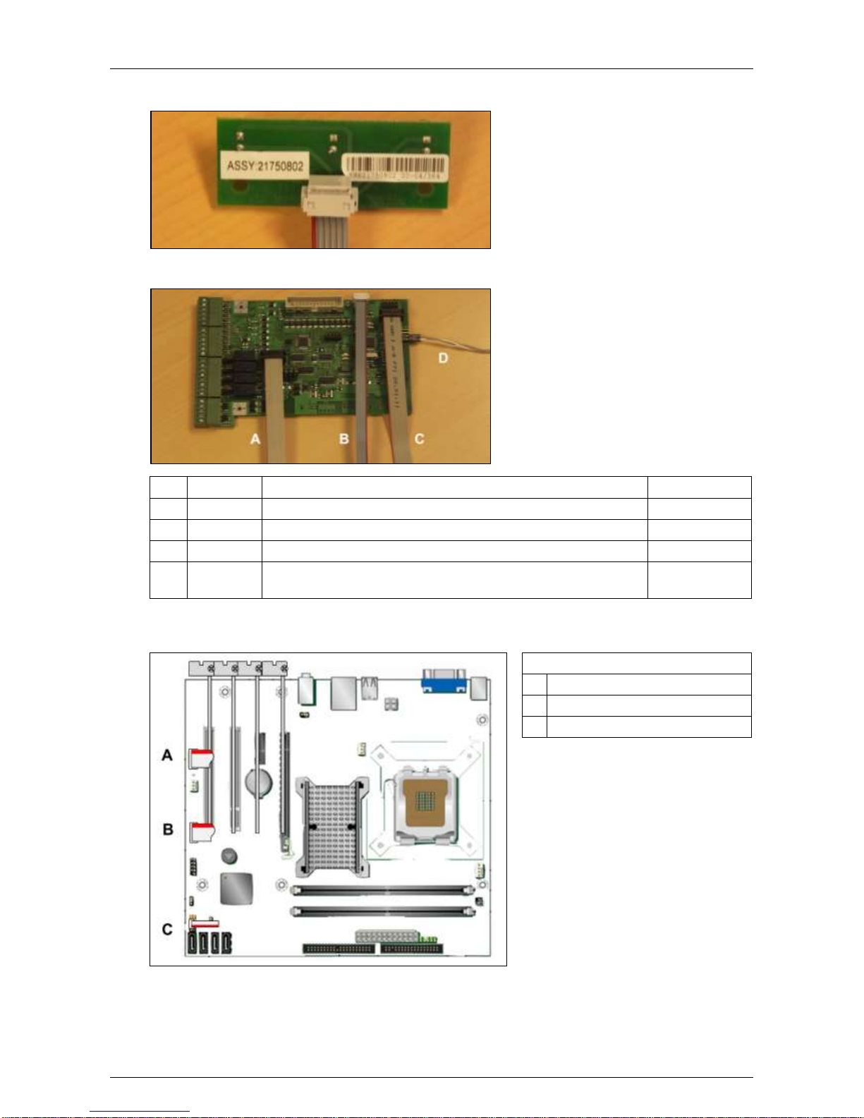
ADPRO® FastTrace™ 2 Series Hardware Installation Manual
21790_05 51
3. Remove the two cables that connect the LED board on the front to the motherboard. The LEDs will be
powered from the Main I/O card (of the 1st set).
4. Before inserting the Main I/O card into the motherboard, connect all necessary cables to the card. See
the table below for an overview of cable connections.
From
To
Cable
A
MIO 1
Motherboard audio
#16540280
B
MIO 1
Front LED board
#21760101
C
MIO 1
Motherboard USB
#16540260
D
MIO 1
Motherboard reset. For more information, see Reset Signal
Details on page 53.
#21760401
5. Insert the I/O card in the appropriate slot. For more information, see Physical Position on page 49.
6. Connect the cables from the I/O card to the motherboard as indicated in the illustrations below.
DG31PR motherboard
A AUDIO (to MIO card)
B USB (to MIO card)
C Reset (to MIO card)
Page 52
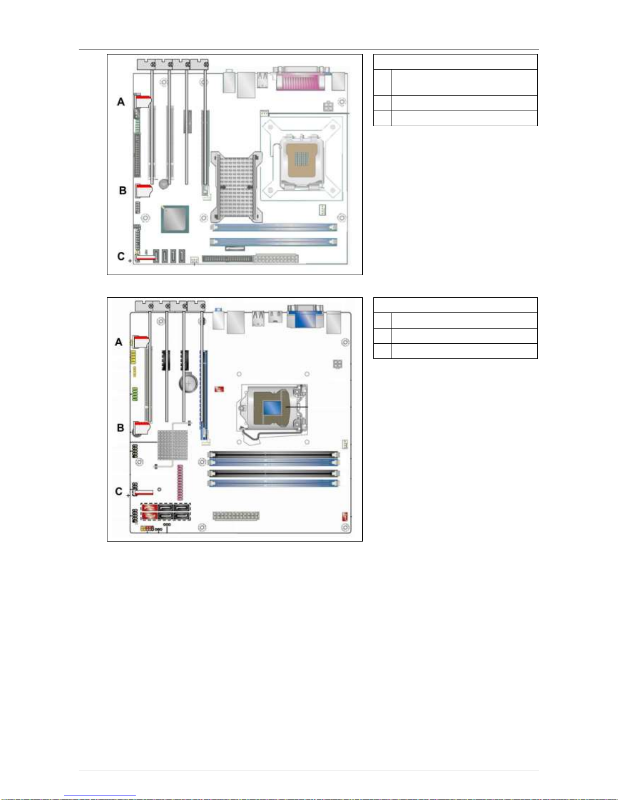
Hardware Installation Manual ADPRO® FastTrace™ 2 Series
52 21790_05
DG41TY motherboard
A AUDIO (to MIO card), use
adapter #16500660
B USB (to MIO card)
C Reset (to MIO card)
DH55TC motherboard
A AUDIO (to MIO card)
B USB (to MIO card)
C Reset (to MIO card)
Page 53
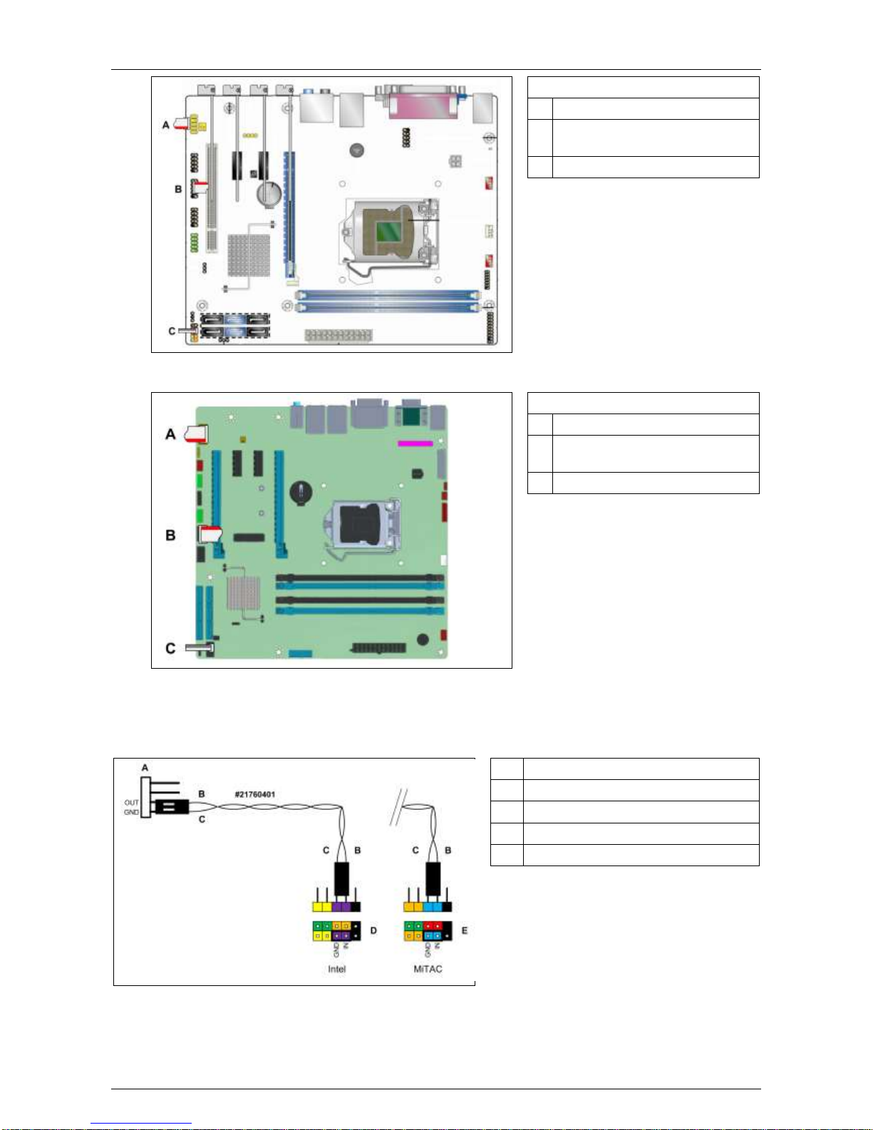
ADPRO® FastTrace™ 2 Series Hardware Installation Manual
21790_05 53
DH61BE motherboard
A AUDIO (to MIO card)
B USB (to MIO card), use adapter
#16500660
C Reset (to MIO card)
PH10LU motherboard
A AUDIO (to MIO card)
B USB (to MIO card), use adapter
#16500665
C Reset (to MIO card)
8.7 Reset Signal Details
A Connector – Main I/O
B Grey wire
C White wire
D Intel motherboard
E MiTAC motherboard
Page 54
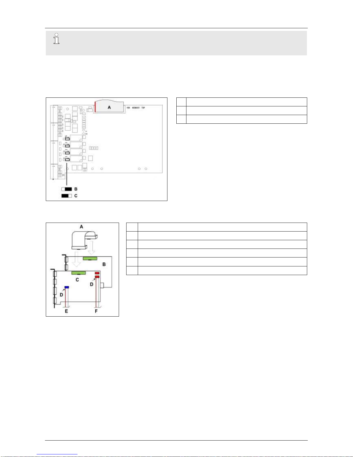
Hardware Installation Manual ADPRO® FastTrace™ 2 Series
54 21790_05
Note
Check the polarity! If you reverse the connection, the motherboard receives a permanent
reset signal.
8.8 Adding an Extension I/O Card
8.8.1 Settings on the Extension I/O Card
A From Main I/O card (#21760300)
B Jumper setting: normally open relay contact
C Jumper setting: normally closed relay contact
8.8.2 Installation
A Flat cable (#21760300)
B Extension I/O card
C Main I/O card
D Red conductor = pin 1
E To motherboard AUDIO connector
F To motherboard USB connector
To install an Extension I/O card, proceed as follows:
1. Insert the extension card into an appropriate slot on the
motherboard. See Physical Position on page 49.
2. Connect the Main I/O card to the Extension I/O card using flat
cable #21760300 (A).
Page 55
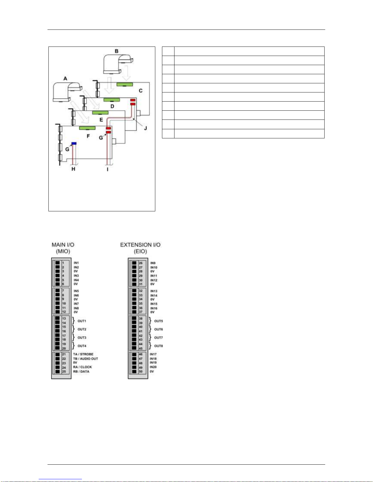
ADPRO® FastTrace™ 2 Series Hardware Installation Manual
21790_05 55
8.9 Adding a Second Set of I/O Cards
A Flat cable (#21760300)
B Flat cable (#21760300)
C EIO 2
D MIO 2
E EIO 1
F MIO 1
G Red conductor = pin 1
H To motherboard AUDIO connector
I To motherboard USB connector (MIO 1 only)
J Flat cable (#16540260)
To insert a second set of I/O cards, proceed as follows:
1. Insert all cards into appropriate slots (see Physical
Position on page 49).
2. Connect MIO 1 to EIO 1
using flat cable #21760300 (A).
3. Connect MIO 2 to EIO 2
using a flat cable #21760300 (B).
4. Connect MIO 1 to MIO 2
using a flat cable #16540260 (J).
8.10 Connection of Inputs/Outputs
Page 56
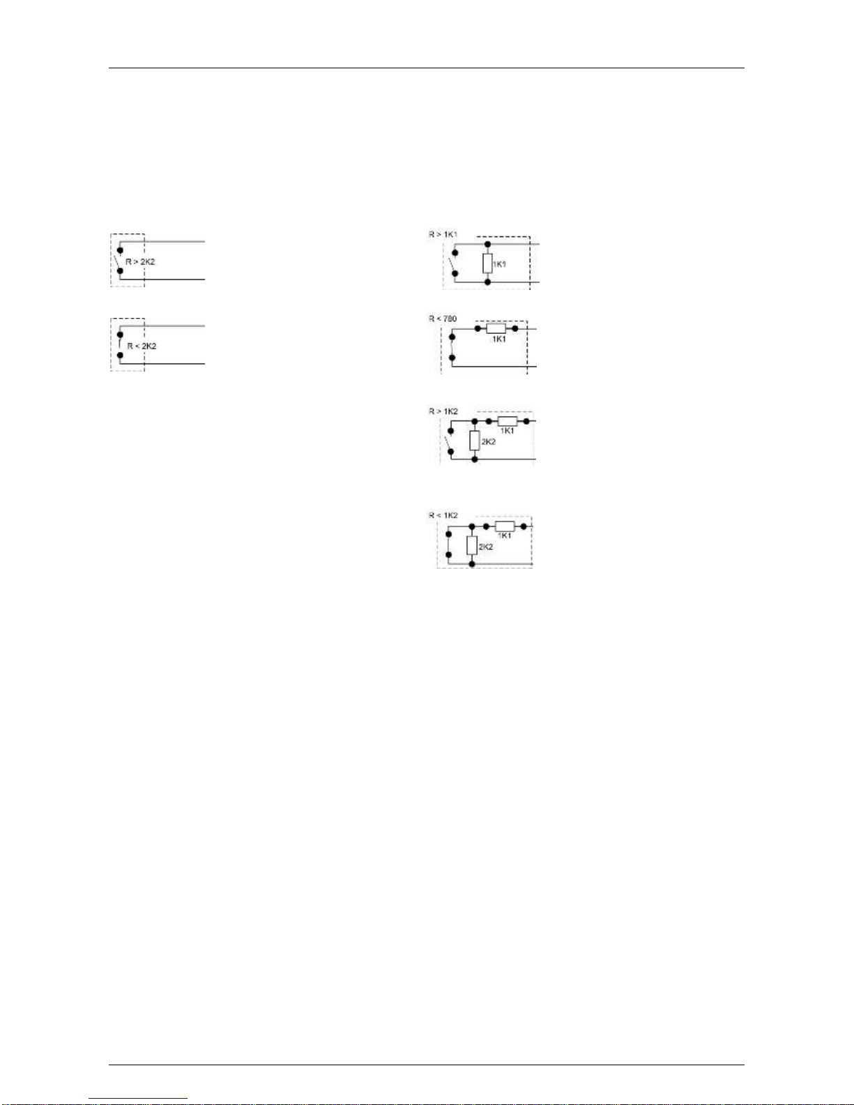
Hardware Installation Manual ADPRO® FastTrace™ 2 Series
56 21790_05
8.11 Configuring the Internal I/O Cards
The FastTrace 2 server automatically detects all connected MIO and EIO cards. To configure the inputs and
outputs, see the XOa Client Software User Manual.
8.12 Input Circuits
Use the ADPRO XOa client to configure the inputs as NEOL, SEOL, or DEOL.
Normally open – NEOL
Short circuit = alarm
Open circuit = idle
Normally open – SEOL
Short circuit = alarm
1K1 = idle
Open circuit = tamper
Normally closed – NEOL
Short circuit = idle
Open circuit = alarm
Normally closed – SEOL
Short circuit = tamper
1K1 = idle
Open circuit = alarm
Normally open – DEOL
Short circuit = tamper
1K1 = alarm
3K3 = idle
Open circuit = tamper
Normally closed – DEOL
Short circuit = tamper
1K1 = idle
3K3 = alarm
Open circuit = tamper
(Default setting)
Page 57
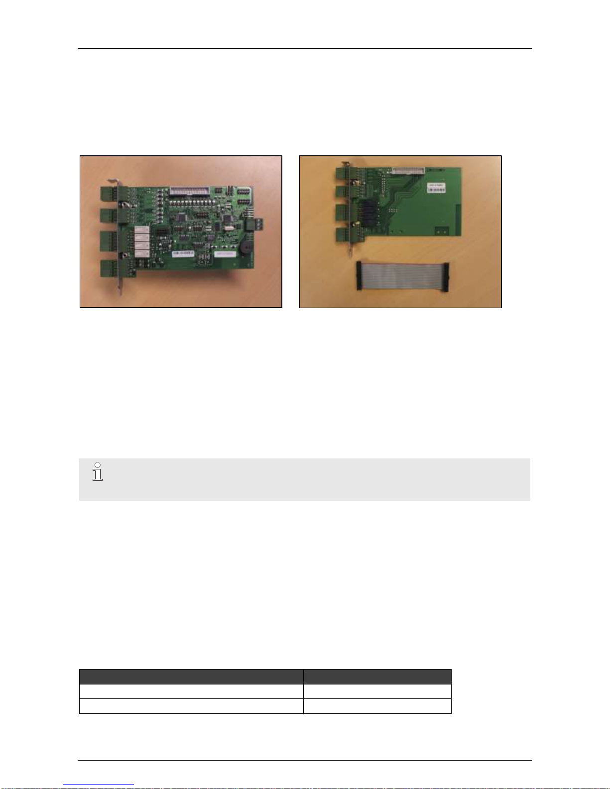
ADPRO® FastTrace™ 2 Series Hardware Installation Manual
21790_05 57
9 Main and Extension I/O Cards Next Generation
9.1 Features
The Main I/O (MIO) and Extension I/O (EIO) Next Generation cards are internal I/O cards, to be fitted inside
the ADPRO FastTrace 2/2E system. They are also called OTB (on-the-board) cards.
Main I/O Next Generation card:
Extension I/O Next Generation card:
These I/O cards offer:
8 tamper-protected inputs and 4 relay outputs (rated 14 VDC @ 1 A) on the Main I/O card
12 tamper-protected inputs and 4 relay outputs on the Extension I/O card
GND for every input
driver for PTZ cameras (half/full duplex RS-485) on the Main I/O card; you need to set 1 jumper to select
2- or 4-wire PTZ
driver for audio module/VM22 audio switcher on the Main I/O card; with improved audio quality
driver on the Main I/O card for front LED indicators of FastTrace 2/2E model
auto-detected Main I/O cards on FastTrace 2/2E system
Note
The Main I/O and Extension I/O cards of the FastTrace 2/2E are compatible with the V3100
HYBRID.
9.2 Possible Configurations
You can configure maximum 2 sets of I/O cards on the FastTrace 2/2E:
Main I/O only
Main I/O + Extension I/O
2 x Main I/O + 1 x Extension I/O
2 x Main I/O + 2 x Extension I/O
9.3 Ordering Information
Use these reference numbers to place your order with Xtralis:
Item
Reference Number
Main I/O card plus mounting set
39544000
Extension I/O card plus mounting set
39544010
Page 58
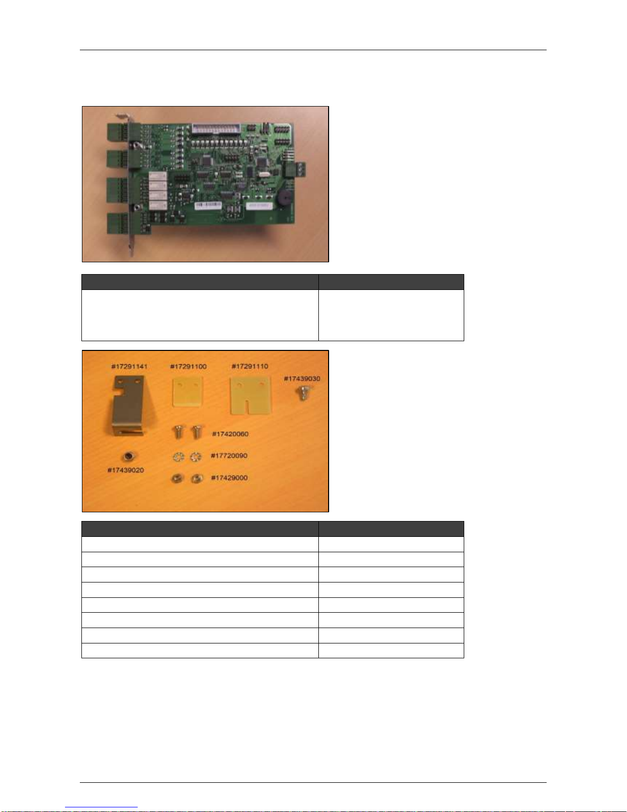
Hardware Installation Manual ADPRO® FastTrace™ 2 Series
58 21790_05
9.4 Material List
9.4.1 Main I/O Card with Mounting Set (#39544000)
Part
Amount + Reference Number
Main I/O card
(incl. mounting bracket,
M3 screws,
and hex spacers)
1 x #39544070
(1 x #17291161)
(2 x #17439030)
(2 x #17210070)
Part
Amount + Reference Number
L-profile
1 x #17291141
Locknut
1 x #17439020
Screw M2.5
2 x #17420060
Nut M2.5
2 x #17429000
Dented washer M2.5
2 x #17720090
Self-locking screw M3
1 x #17439030
PCI Inserter
1 x #17291100
PCI Express Inserter
1 x #17291110
Page 59
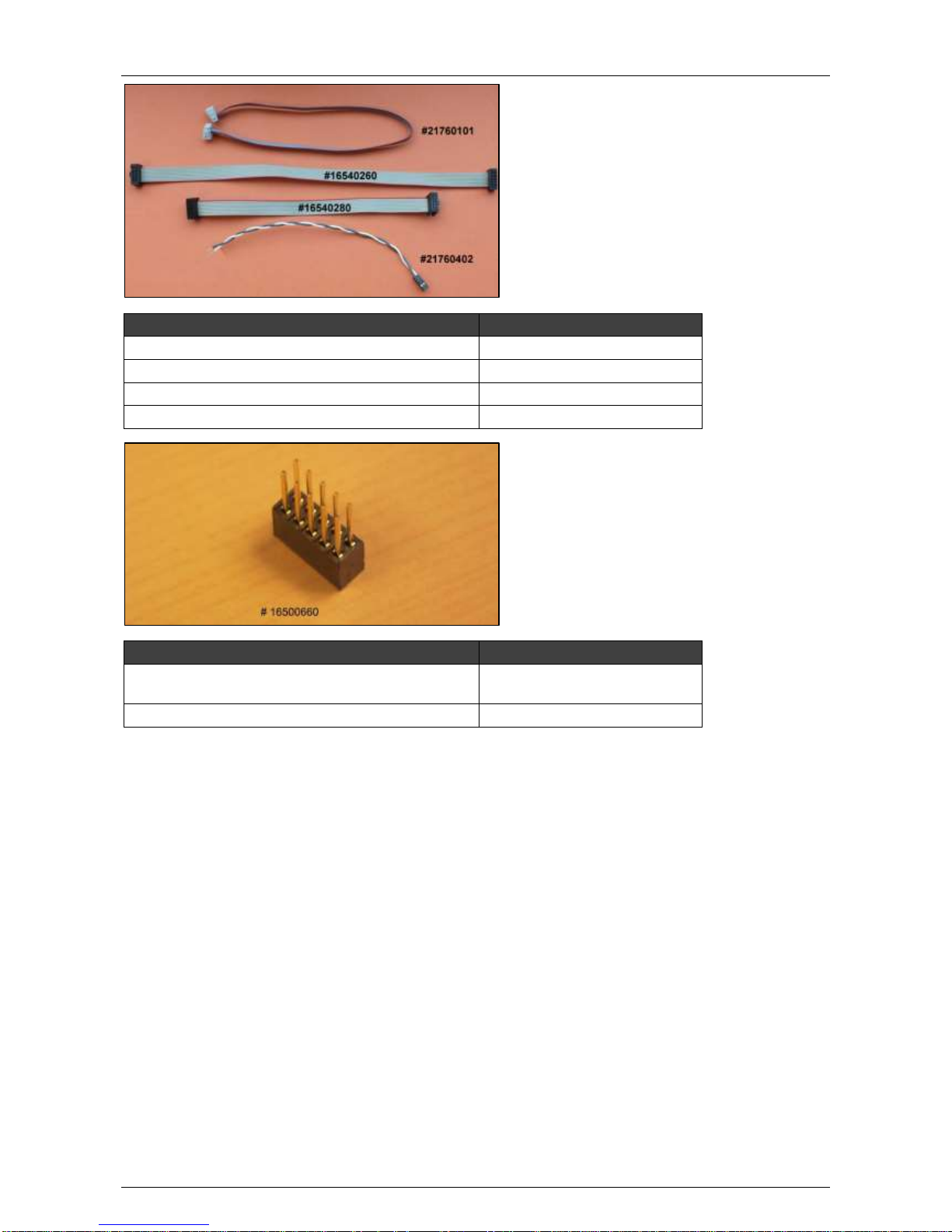
ADPRO® FastTrace™ 2 Series Hardware Installation Manual
21790_05 59
Part
Amount + Reference Number
Flat cable (6 pins x 35 cm)
1 x #21760101
Flat cable (10 pins x 20 cm) for USB
1 x #16540260
Flat cable (10 pins x 30 cm) for audio
1 x #16540280
Reset cable
1 x #21760402
Part
Amount + Reference Number
Connector adapter for DG41TY and DH61BE
motherboards
1 x #16500660
Connector adapter for PH10LU motherboard
1 x #16500665
DG41TY: place the adapter on the AUDIO connector.
DH61BE: place the adapter on the USB connector.
PH10LU: place the adapter on the USB connector.
Page 60
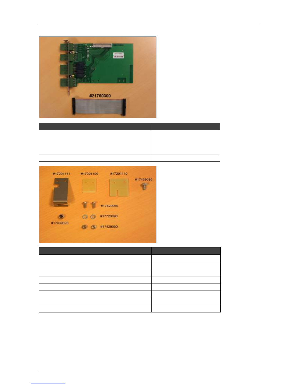
Hardware Installation Manual ADPRO® FastTrace™ 2 Series
60 21790_05
9.4.2 Extension I/O Card with Mounting Set (#39544010)
Part
Amount + Reference Number
Extension I/O card
(incl. mounting bracket,
M3 screws, and
hex spacers)
1 x #39544080
(1 x #17291161)
(2 x #17439030)
(2 x #17210070)
Flat cable (26 pins)
1 x #21760300
Part
Amount + Reference Number
L-profile
1 x #17291141
Locknut
1 x #17439020
Screw M2.5
2 x #17420060
Nut M2.5
2 x #17429000
Dented washer M2.5
2 x #17720090
Self-locking screw M3
1 x #17439030
PCI Inserter
1 x #17291100
PCI Express Inserter
1 x #17291110
9.5 Physical Position
Insert the first set of I/O cards in the two furthermost slots (= nearest to the power supply). Use the L-shaped
brackets to fix the cards to the chassis. Insert the Main I/O card in the furthermost slot (= slot 6).
Insert the second set in the PCI or PCI Express slots on the motherboard using the included PCI or PCI
Express Inserters. Depending on the type of motherboard, you need either a PCI or PCI Express Inserter.
Page 61
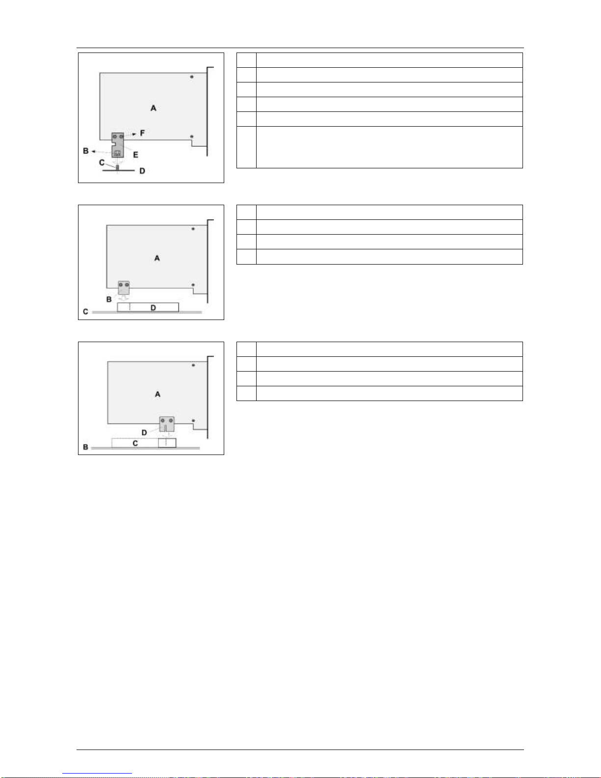
ADPRO® FastTrace™ 2 Series Hardware Installation Manual
21790_05 61
Mounting on chassis:
A I/O card, bottom side
B Locknut (#17439010)
C M3 stud
D Chassis
E L-shaped metal bracket (#17291141) – on top side
F Screw M2.5 (#17420060)
Nut M2.5 (#17429000)
Dented washer M2.5 (#17720090)
PCI connector:
A I/O card, bottom side
B PCI inserter (#17291100)
C Motherboard
D PCI connector
PCI Express connector:
A I/O card, bottom side
B Motherboard
C PCI Express connector
D PCI Express inserter (#17291110)
Page 62
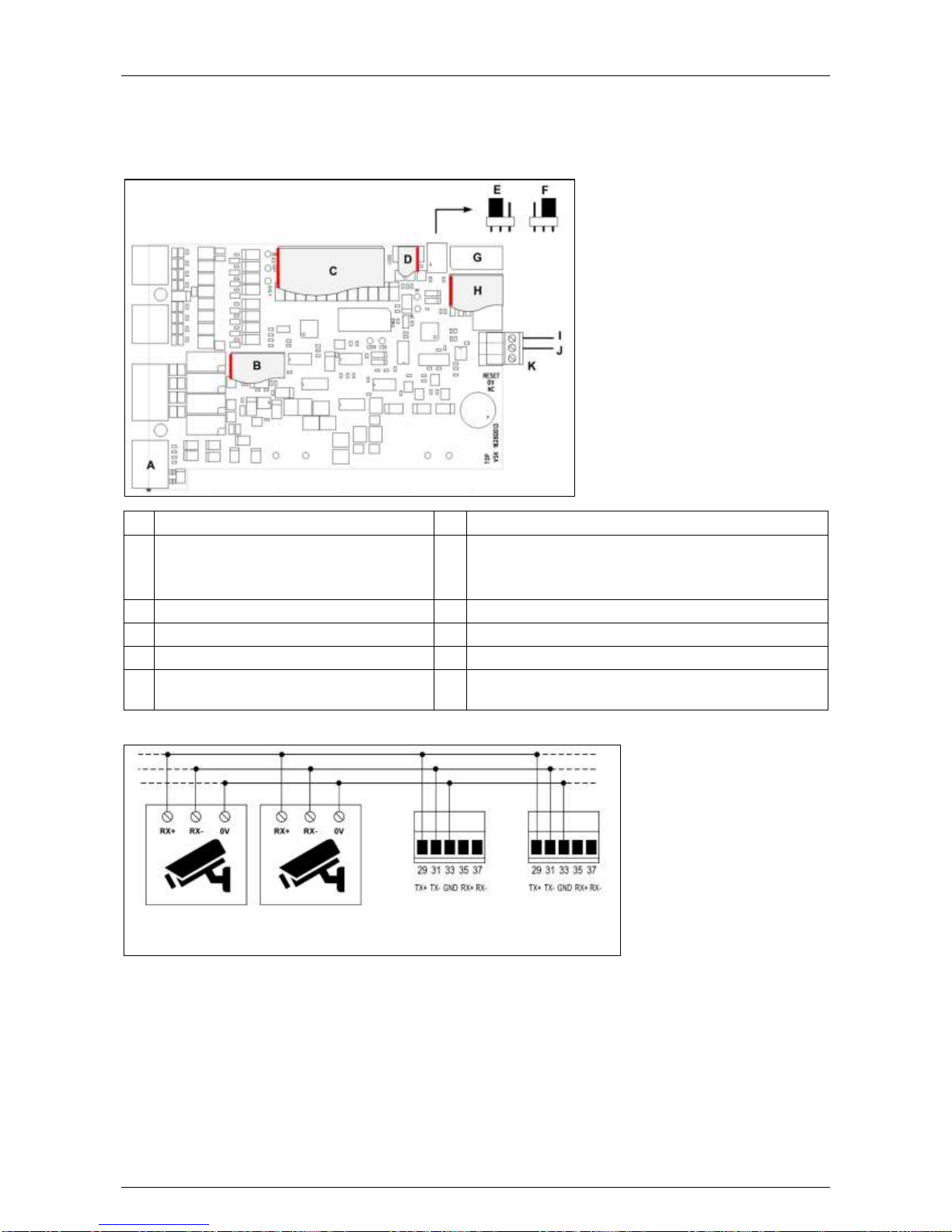
Hardware Installation Manual ADPRO® FastTrace™ 2 Series
62 21790_05
9.6 Settings on the Main I/O Card
If you are connecting PTZ cameras from the same RS-485 bus to multiple FastTrace 2 servers, set the
RS-485 PTZ jumper on the Main I/O card to the 2-wire (PTZ) position.
RS-485 cable length: max. 1200 m.
A
PTZ and audio (VM22)
G
USB port; to second Main I/O card
B
To AUDIO on motherboard (#16540280)
H
To nearest USB port on motherboard (#16540260)
On 1st Main I/O: addressed as /dev/ttyU6.
On 2nd Main I/O: addressed as /dev/ttyU8.
C
To Extension I/O card (#21760300)
I
Reset cable, grey wire
D
To front LEDs (#21760101)
J
Reset cable, white wire
E
RS-485 PTZ jumper: 2-wire setting
K
Reset signal from motherboard (#2176040*)
F
RS-485 PTZ jumper: 4-wire setting
(default setting)
PTZ cameras
Main I/O cards Next
Generation
9.7 Installation
To install the Main I/O card, proceed as follows:
1. Switch off the power supply, and remove the lid from the server.
2. Remove any superfluous blind brackets.
Page 63
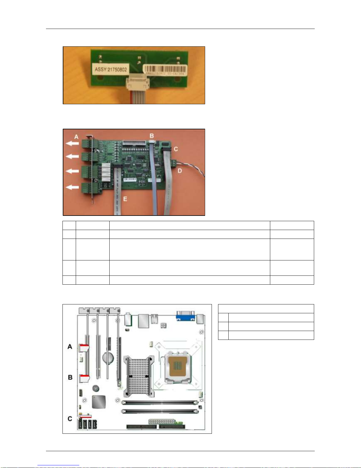
ADPRO® FastTrace™ 2 Series Hardware Installation Manual
21790_05 63
3. Remove the two cables that connect the LED board on the front to the motherboard. The LEDs will be
powered from the Main I/O card (of the 1st set).
4. Remove the female connectors (A, see figure below) from the Main I/O card before installing.
5. Before inserting the Main I/O card into the motherboard, connect all necessary cables to the card. See
the table below for an overview of cable connections.
From
To
Cable
B
MIO 1
Front LED board
#21760101
C
MIO 1
Motherboard USB (Intel motherboard: place adapter
#16500660 on the USB connector; MiTAC motherboard: place
adapter #16500665 on the USB connector)
#16540260
D
MIO 1
Motherboard reset. For more information, see Reset Signal
Details on page 65.
#21760402
E
MIO 1
Motherboard audio
#16540280
6. Insert the I/O card in the appropriate slot. For more information, see Physical Position on page 60.
7. Connect the cables from the I/O card to the motherboard as indicated.
DG31PR motherboard
A AUDIO (to MIO card)
B USB (to MIO card)
C Reset (to MIO card)
Page 64
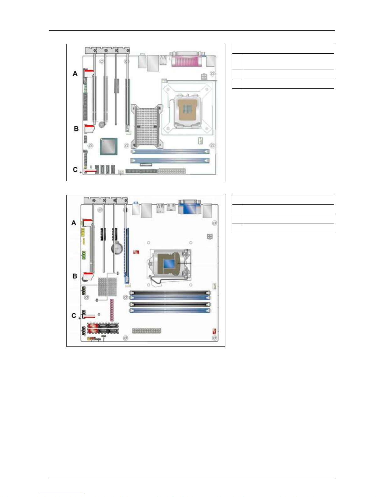
Hardware Installation Manual ADPRO® FastTrace™ 2 Series
64 21790_05
DG41TY motherboard
A AUDIO (to MIO card), use
adapter #16500660
B USB (to MIO card)
C Reset (to MIO card)
DH55TC motherboard
A AUDIO (to MIO card)
B USB (to MIO card)
C Reset (to MIO card)
Page 65
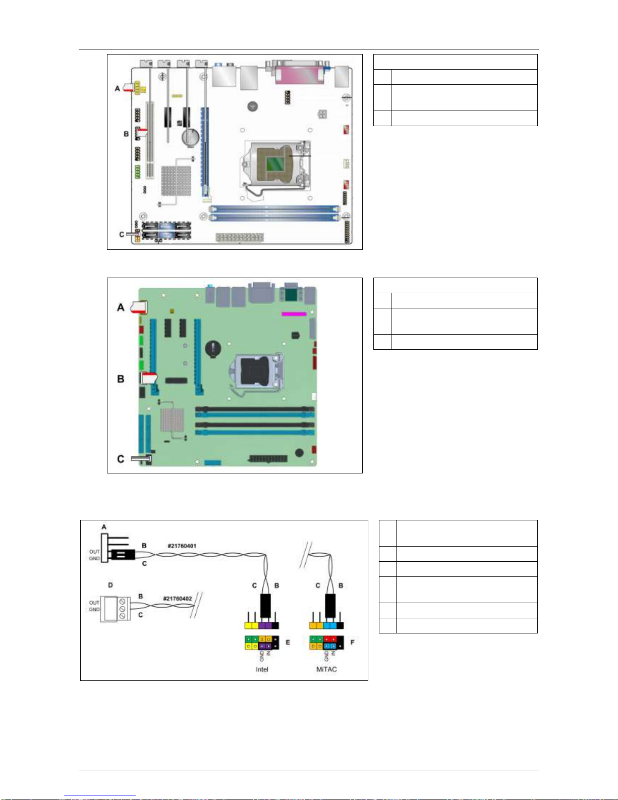
ADPRO® FastTrace™ 2 Series Hardware Installation Manual
21790_05 65
DH61BE motherboard
A AUDIO (to MIO card)
B USB (to MIO card), use adapter
#16500660
C Reset (to MIO card)
PH10LU motherboard
A AUDIO (to MIO card)
B USB (to MIO card), use adapter
#16500665
C Reset (to MIO card)
9.8 Reset Signal Details
A Connector – Main I/O and
Main I/O Next Generation
B Grey wire
C White wire
D Connector – Main I/O Next
Generation only
E Intel motherboard
F MiTAC motherboard
The Main I/O Next Generation card has two connectors for the reset cable: a pin connector (A) and a screw
terminal (D). Depending on the plug that is available on the reset cable, you can connect it to either
connector on the new Main I/O cards.
On older Main I/O cards, only the pin connector is available.
Page 66
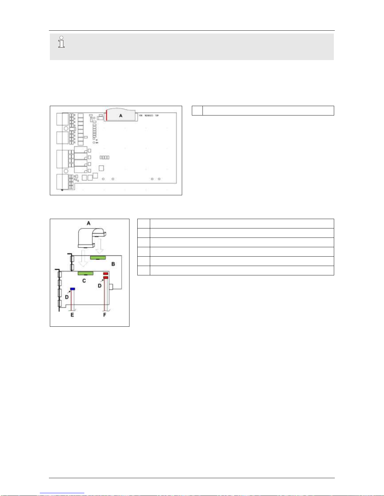
Hardware Installation Manual ADPRO® FastTrace™ 2 Series
66 21790_05
Note
Check the polarity! If you reverse the connection, the motherboard receives a permanent reset
signal.
9.9 Adding an Extension I/O Card
9.9.1 Settings on the Extension I/O Card
A From Main I/O card (#21760300)
No settings are required on the Extension I/O card.
9.9.2 Installation
A Flat cable (#21760300)
B Extension I/O card
C Main I/O card
D Red conductor = pin 1
E To motherboard AUDIO connector
F To motherboard USB connector
To install an Extension I/O card, proceed as follows:
1. Insert the extension card into an appropriate slot on the
motherboard. For more information, see Physical Position on
page 60.
2. Connect the Main I/O card to the Extension I/O card using flat
cable #21760300 (A).
Page 67
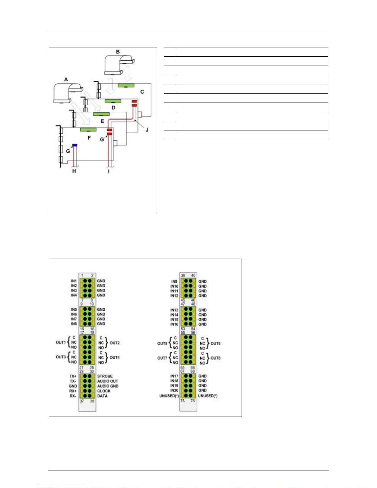
ADPRO® FastTrace™ 2 Series Hardware Installation Manual
21790_05 67
9.10 Adding a Second Set of I/O Cards
A Flat cable (#21760300)
B Flat cable (#21760300)
C EIO 2
D MIO 2
E EIO 1
F MIO 1
G Red conductor = pin 1
H To motherboard AUDIO connector
I To motherboard USB connector (MIO 1 only)
J Flat cable (#16540260)
To insert a second set of I/O cards, proceed as follows:
1. Insert all cards into appropriate slots (see Physical
Position on page 60).
2. Connect MIO 1 to EIO 1
using flat cable #21760300 (A).
3. Connect MIO 2 to EIO 2
using a flat cable #21760300 (B).
4. Connect MIO 1 to MIO 2
using a flat cable #16540260 (J).
9.11 Connection of Inputs/Outputs
9.11.1 Overview of Inputs and Outputs
Main I/O
Extension I/O
(*) 75 and 76 are interconnected.
Depending on the type, the Next Generation cards can be equipped with one of two different spring insertion
connectors: Dinkle (standard) or Phoenix. For both types you need a 2 mm slotted screwdriver.
Page 68
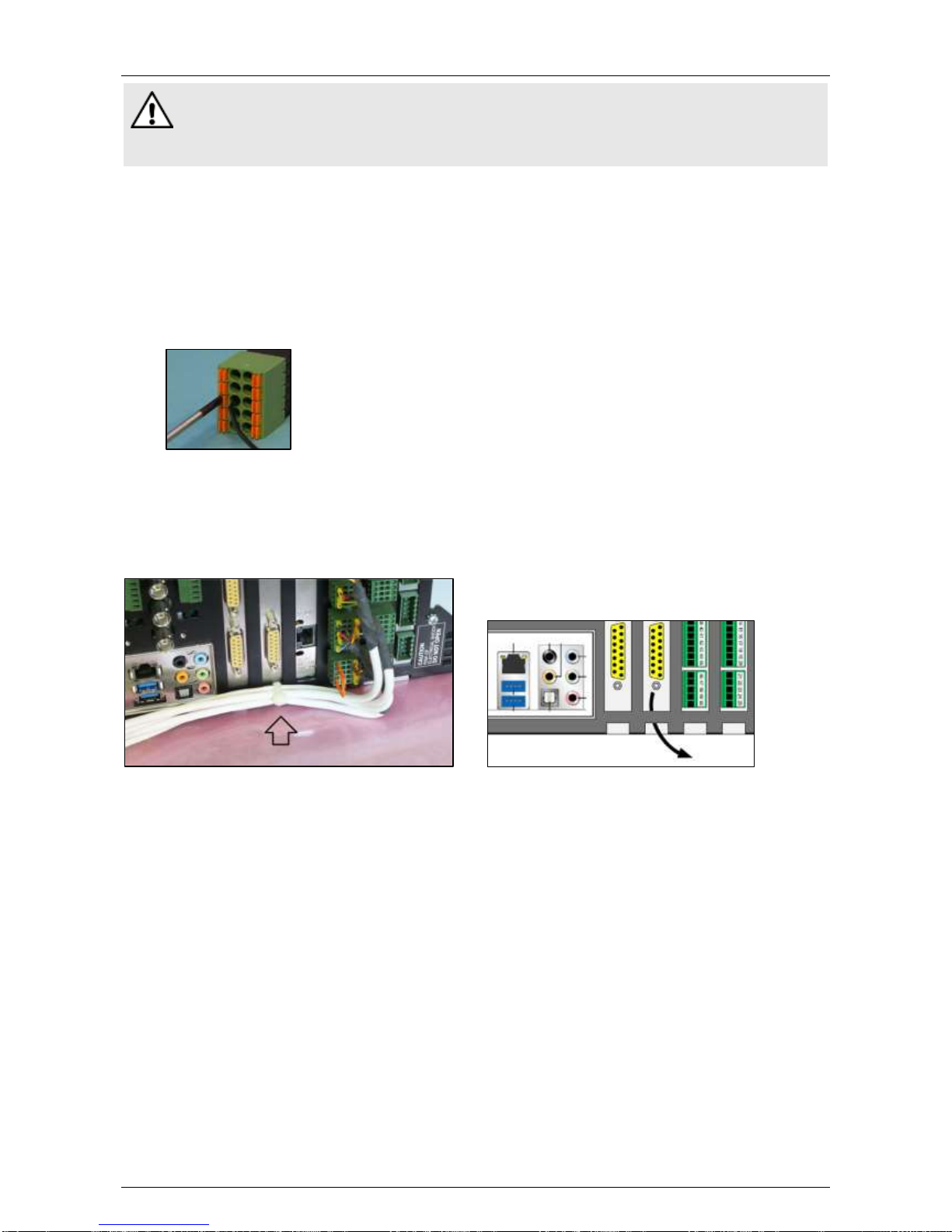
Hardware Installation Manual ADPRO® FastTrace™ 2 Series
68 21790_05
Warning!
Although the pictures below show only the connector, it is strongly recommended to connect the
wires with the connectors plugged into the card. Wiring a handheld connector may cause
injuries.
9.11.2 Connecting Inputs/Outputs
Wiring to Dinkle and Phoenix connectors is identical; except that the position of tabs and holes is swapped.
The picture in the procedure below shows a Phoenix connector.
To connect inputs/outputs, proceed as follows:
1. Push the slotted tab firmly inwards with the screwdriver.
2. Insert the stripped wire (6–7 mm) into the corresponding round hole as deeply as possible.
3. Release the tab and pull the wire to check if it is properly fitted.
Wire gauge:
Solid and stranded: 16–24 AWG
(diam. 1.3–0.5 mm)
9.11.3 Cable Strain Relief
After connecting all the wires, use a tie-wrap to attach the cables to the chassis. Run the tie-wrap through
one of the extension card openings in the chassis as shown below. The tie-wrap serves as a strain relief and
makes sure that the wiring stays in place when handling the FastTrace 2 unit.
9.12 Configuring the Internal I/O Cards
The FastTrace 2 server automatically detects all connected MIO and EIO cards. To configure the inputs and
outputs, see the XOa Client Software User Manual.
Page 69
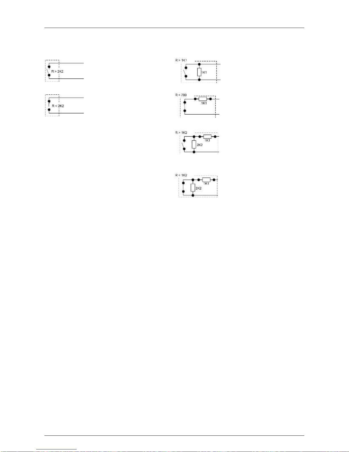
ADPRO® FastTrace™ 2 Series Hardware Installation Manual
21790_05 69
9.13 Input Circuits
Use the ADPRO XOa client to configure the inputs as NEOL, SEOL, or DEOL.
Normally open – NEOL
Short circuit = alarm
Open circuit = idle
Normally open – SEOL
Short circuit = alarm
1K1 = idle
Open circuit = tamper
Normally closed – NEOL
Short circuit = idle
Open circuit = alarm
Normally closed – SEOL
Short circuit = tamper
1K1 = idle
Open circuit = alarm
Normally open – DEOL
Short circuit = tamper
1K1 = alarm
3K3 = idle
Open circuit = tamper
Normally closed – DEOL
Short circuit = tamper
1K1 = idle
3K3 = alarm
Open circuit = tamper
(Default setting)
Page 70
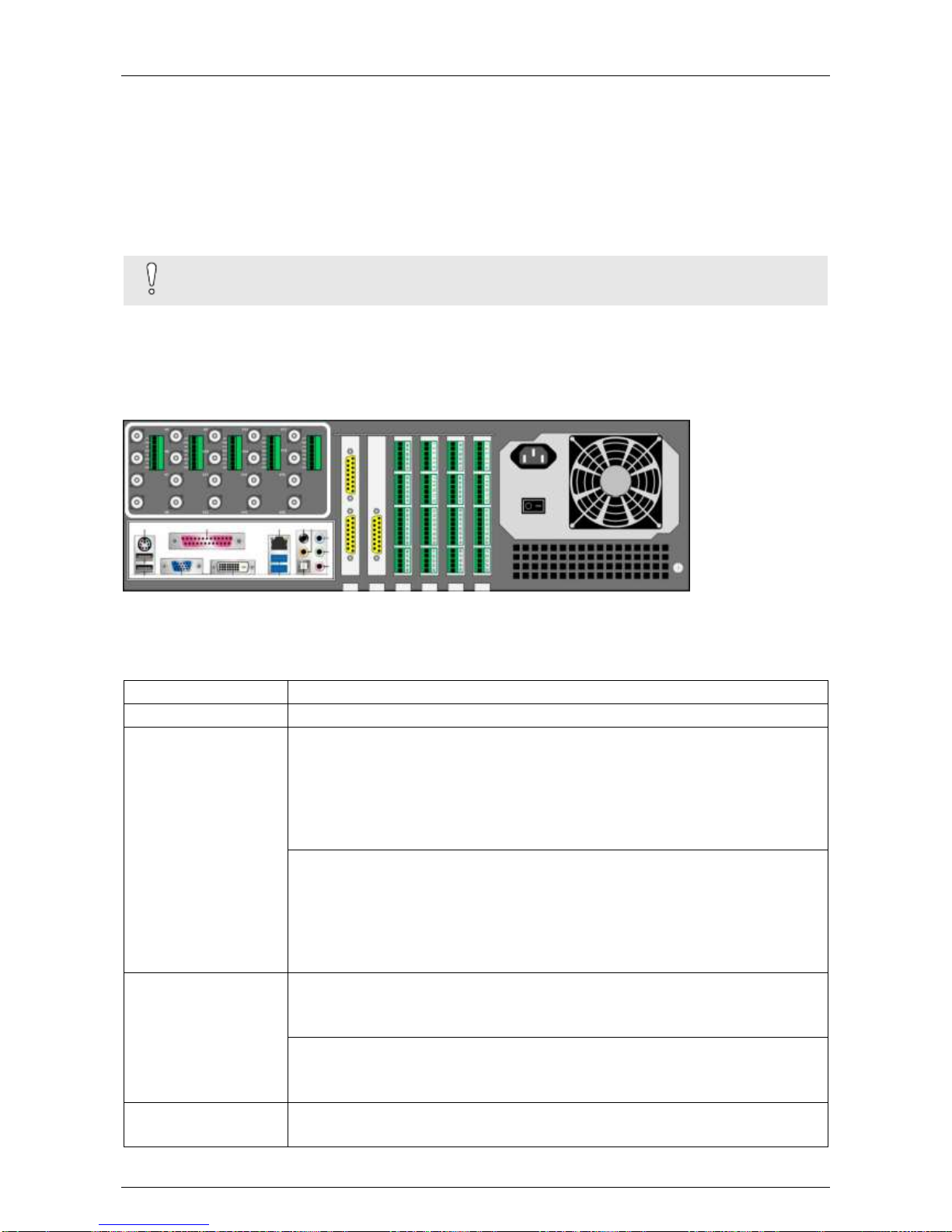
Hardware Installation Manual ADPRO® FastTrace™ 2 Series
70 21790_05
10 Required Encoder (A/V) Card
You use different video cards (encoder cards) with different motherboards in the FastTrace 2 video system:
Use DS40xx-HCI encoder cards with the Intel DG31PR and Intel DG41TY motherboards.
Use DS42xx-HFVI-E encoder cards with the Intel DH55TC, Intel DH61BE, and MiTAC PH10LU
motherboards.
Do not mix different cards within the same video system.
Caution!
The XOa 3 firmware does not support DS40xx-HCI encoder cards.
10.1 Number of Cameras
Depending on the installed encoder card(s), you have 4, 8, 12, 16, or 20 analogue A/V inputs. You can
connect analogue cameras to the rear of the FastTrace 2 video system using BNC RG59 or RG11 cables.
Each analogue camera needs a separate BNC input.
10.2 Technical Specifications of Analogue Cameras
video standard
PAL or NTSC
video compression
H.264
video resolution
PAL:
QCIF (176 x 144)
CIF (352 x 288)
2CIF (704 x 288)
DCIF (528 x 384) (not available with DS42xx A/V cards)
4CIF (704 x 576)
NTSC:
QSIF (176 x 120)
SIF (352 x 240)
2SIF (704 x 240)
DSIF (528 x 320) (not available with DS42xx A/V cards)
4SIF (704 x 480)
frames per second
PAL:
CIF, 2CIF, DCIF: 25 fps / camera
4CIF: 15 fps / camera (25 fps with DS42xx A/V cards)
NTSC:
QSIF, SIF, 2SIF, DSIF: 30 fps / camera
4SIF: 15 fps / camera (25 fps with DS42xx A/V cards)
audio
1 input per analogue camera, with screw connectors
input level: 2.0 Vp-p; 1000 ohm
Page 71
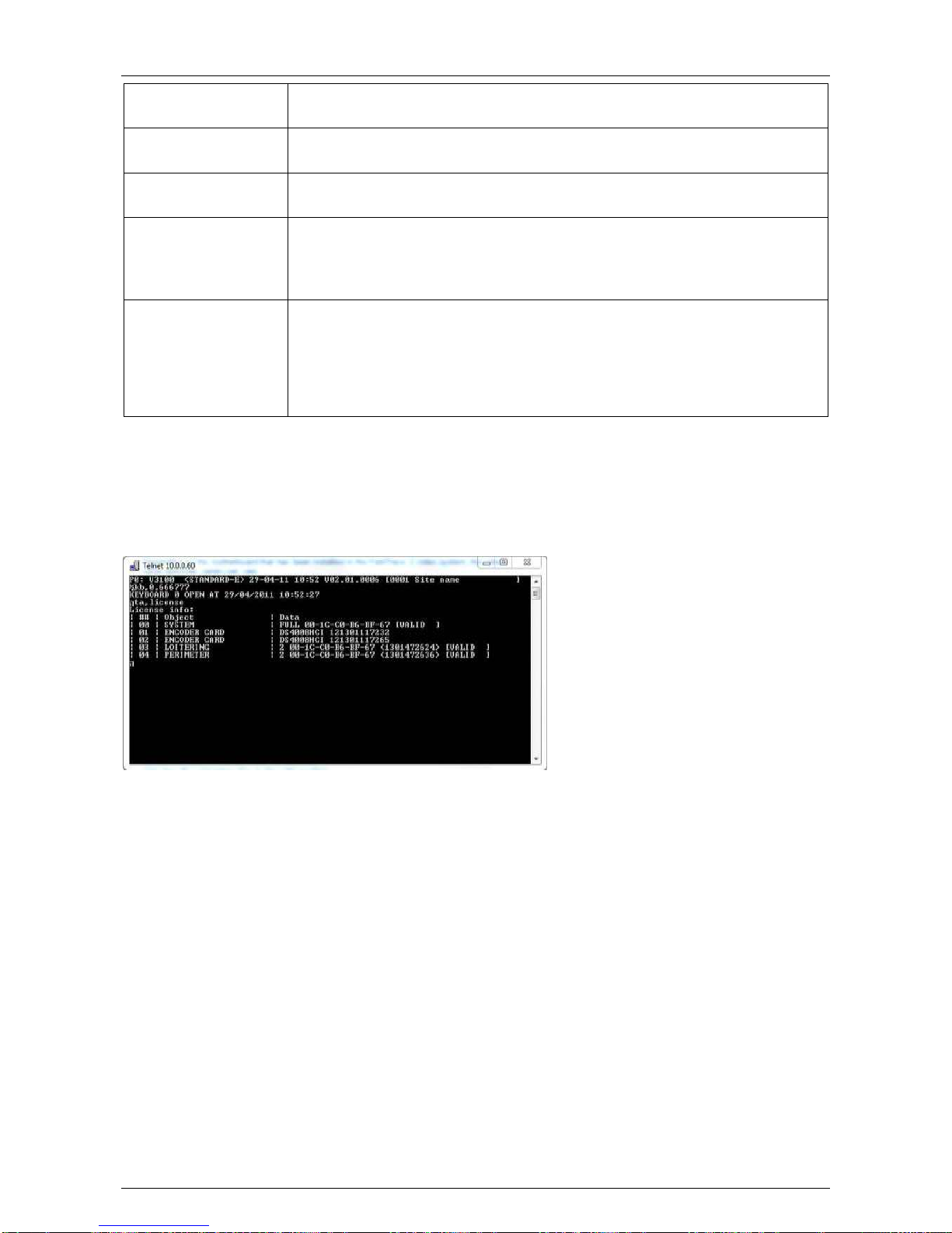
ADPRO® FastTrace™ 2 Series Hardware Installation Manual
21790_05 71
audio compression
OggVorbis Codec 16 kbps (DS40xx cards)
OggVorbis Codec G711 (DS42xx cards)
bandwidth
Compression, fps, and quality are remotely adjustable.
You can specify a bandwidth limit in the XOa client software.
bandwidth
consumption
6 fps CIF/SIF: 70 kbps
12 fps 4CIF/SIF: 400 kbps in optimal quality
PTZ
Several protocols available
For a detailed list, see the XOa Client Software User Manual.
For more information on the possible PTZ connections, see PTZ Cameras on
page 80.
management
Internet Explorer (installs the XOa client software)
(IMPORTANT: turn off Protected Mode)
VSKWin software
M3000 software
VideoCentral Platinum software
third-party software (e.g. EMS by HeiTel)
10.3 Replacing a Video Card
First check your license (either via the Status page in the XOa client software, or via a Telnet connection
using the command ta,license). If no license information is listed, your license may have been deleted (by
accident). Contact your dealer for a new license.
(For more information, see System License on page 13).
Trace the faulty video card by checking live images of the connected cameras in the XOa client. Switch off
the power supply and remove the faulty video card. Insert the new video card in the slot where you removed
the old one.
Page 72
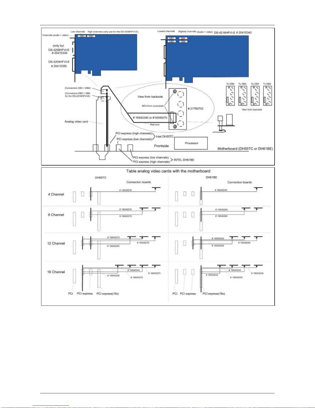
Hardware Installation Manual ADPRO® FastTrace™ 2 Series
72 21790_05
It is recommended to return the faulty video card to your reseller.
Switch on the power supply and reboot the video system. The replacement part will include a new license.
Upload the received license file to the server. For more information on uploading files to the video system,
see the XOa Client Software User Manual.
10.4 Adding a Video Card
Switch off the power supply. Open the casing and insert the new video card (in a free slot). Close the casing
and switch on the power supply. The new video card will include a new license on delivery. Upload the
received license file to the server.
For more information on uploading files to the server, see the XOa Client Software User Manual.
Page 73
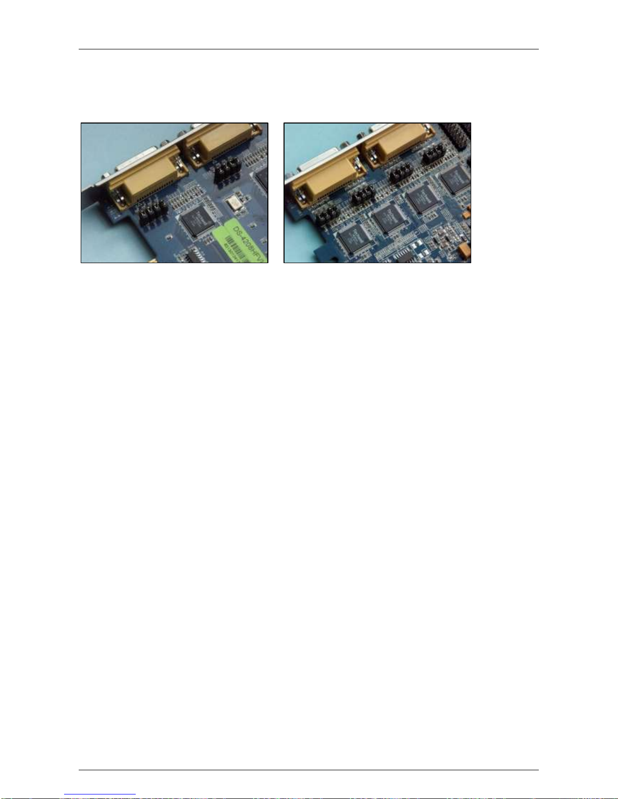
ADPRO® FastTrace™ 2 Series Hardware Installation Manual
21790_05 73
10.5 Video Input Termination (75 Ohm/High Impedance)
This is only available on the latest version of the 8 or 16 channel video cards.
Jumpers JP1–JP8/16 determine whether the corresponding video input is terminated with 75 ohm (if jumper
is placed) or not (if jumper is removed).
8-channel A/V card
16-channel A/V card
Page 74
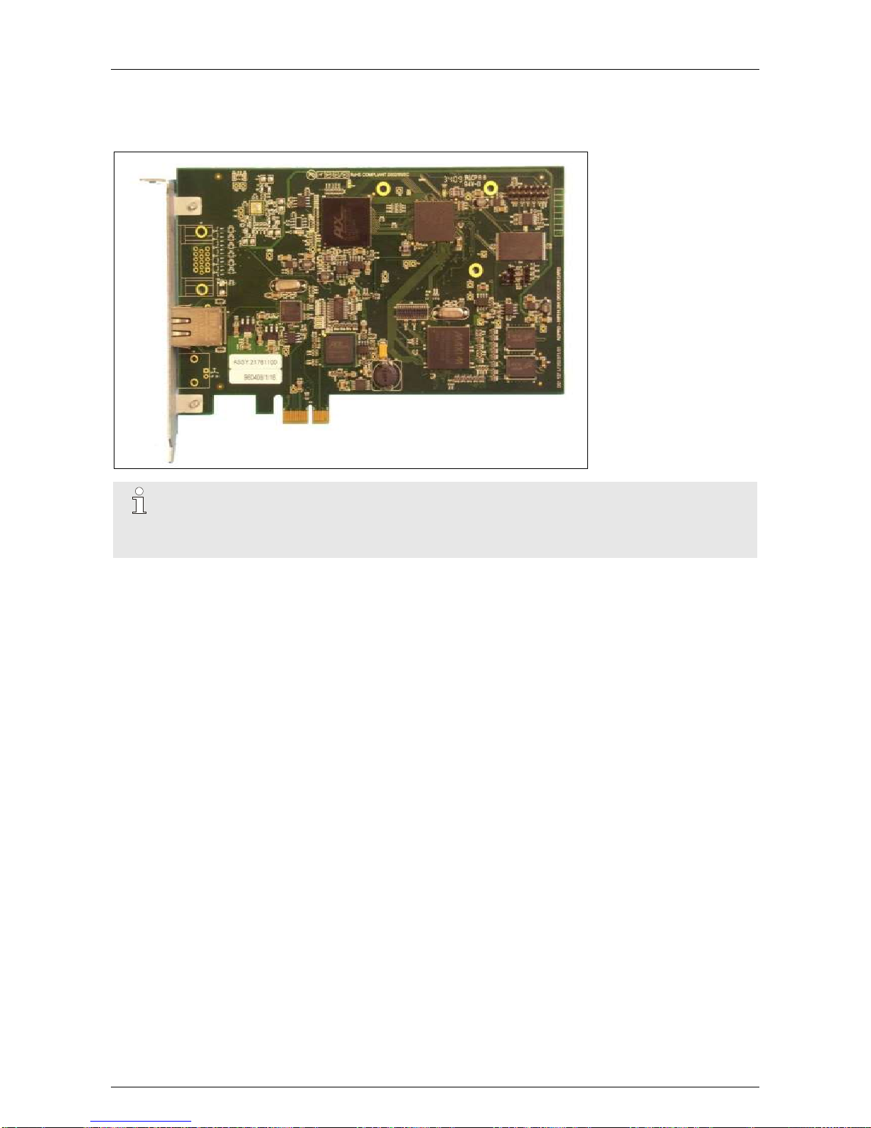
Hardware Installation Manual ADPRO® FastTrace™ 2 Series
74 21790_05
11 HIPI Card for IP Cameras
The HIPI card offers an isolated LAN network (10/100/1000 Mbps on RJ45 connector) to connect IP
cameras.
Note
The HIPI card can also function as Ethernet card from version 2.9 onwards. The HIPI card is no
longer used for new FastTrace 2 units. It is not compatible with the MiTAC PH10LU
motherboard.
11.1 Ethernet Settings
The Ethernet connection of your FastTrace 2 server and the Ethernet connections of the installed HIPI
card(s) must be set on different IP ranges! IP cameras can be connected on either HIPI card, as shown in
the illustration below, with a maximum of 8 cameras per HIPI card. Yet, if you have installed two HIPI cards
you can connect up to 16 IP cameras to the same switch/HIPI card.
Page 75
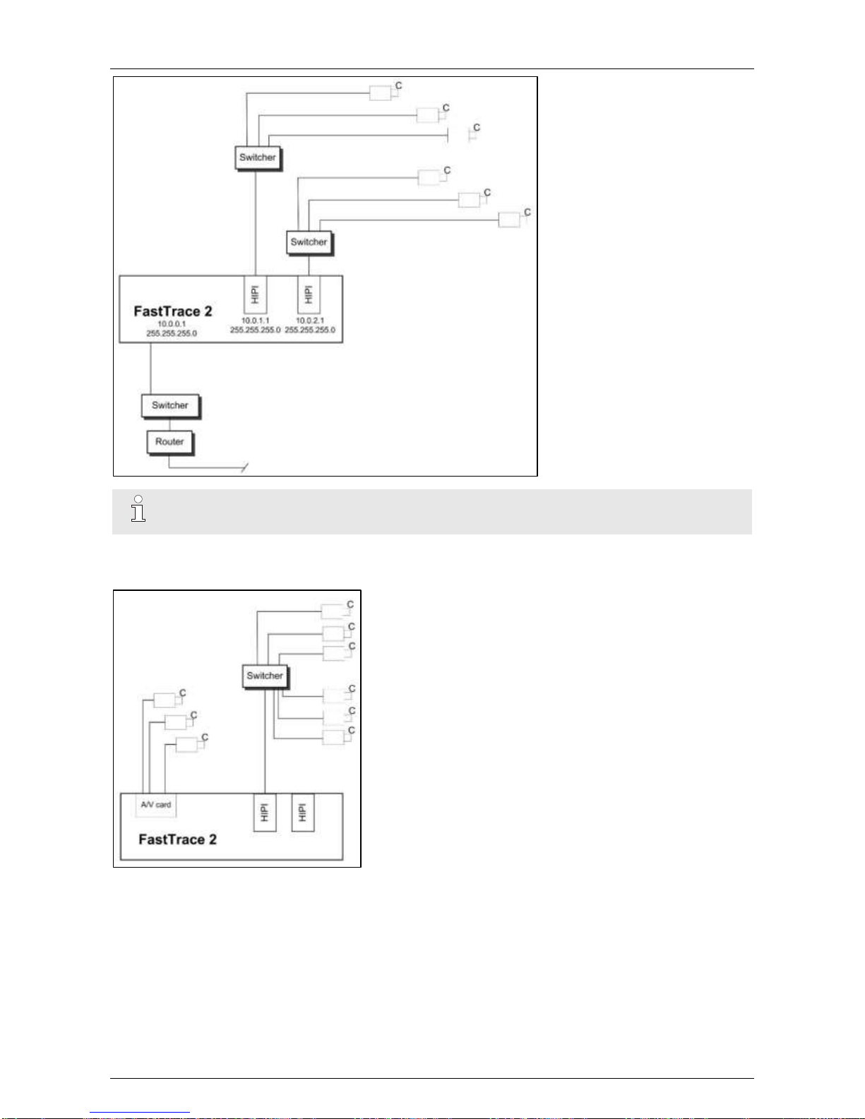
ADPRO® FastTrace™ 2 Series Hardware Installation Manual
21790_05 75
Note
The HIPI Ethernet interfaces use ETH1 and/or ETH2, not ETH0.
In case of 2 HIPI cards with IP only, there is no restriction in which camera is connected to which port.
A 16-camera network can be connected to a single port.
The HIPI card is automatically detected by the FastTrace 2 video system. Each HIPI card must be configured
with a different IP address and a subnet mask. As a consequence, 3 IP ranges are possible on a
FastTrace 2 configuration:
IP range of the FastTrace 2 video system
IP range of the first HIPI card
IP range of the second HIPI card
All IP cameras connected to the HIPI card (by means of a switch) must be set in the same IP range as the
HIPI card.
Page 76
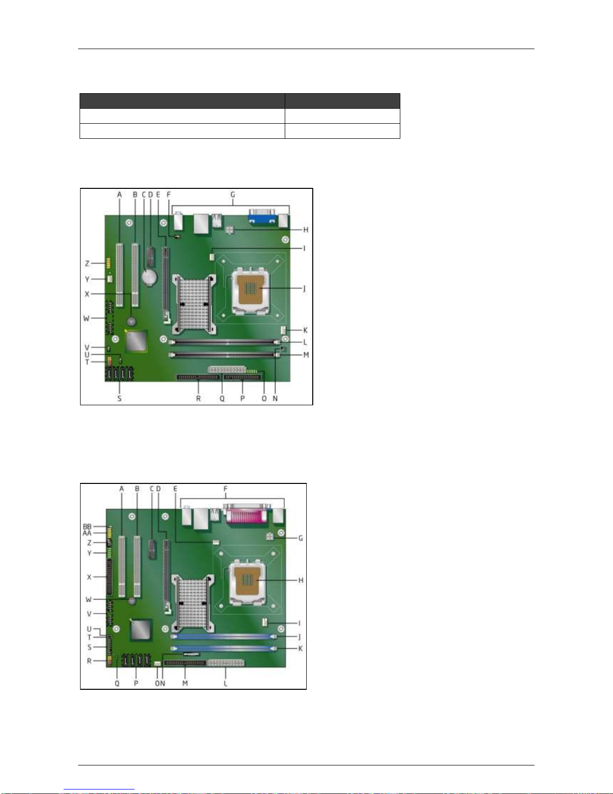
Hardware Installation Manual ADPRO® FastTrace™ 2 Series
76 21790_05
11.2 Adding a HIPI Card
Use these reference numbers when ordering your HIPI card with Xtralis:
Extension Board
Reference Number
HIPI card: card only
39544300
Hybrid HIPI card: card + mounting set
39544320
11.2.1 Placement on the Intel DG31PR Motherboard
Insert the first HIPI card in PCI Express slot E. Insert the second HIPI card in PCI Express slot D.
The card in slot E is assigned as ETH1 in the system. For more information, see the manual of the
motherboard.
11.2.2 Placement on the Intel DG41TY Motherboard
Insert the first HIPI card in PCI Express slot D. Insert the second HIPI card in PCI Express slot C.
The card in slot D is assigned as ETH1 in the system. For more information, see the manual of the
motherboard.
Page 77
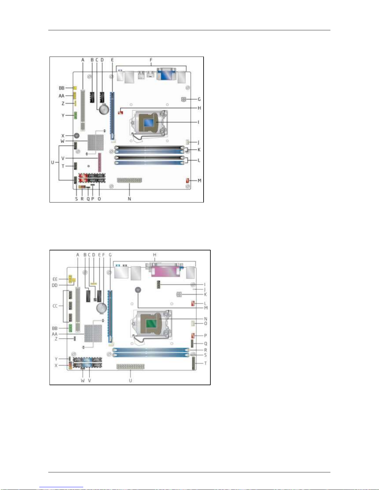
ADPRO® FastTrace™ 2 Series Hardware Installation Manual
21790_05 77
11.2.3 Placement on the Intel DH55TC Motherboard
Insert the first HIPI card in PCI Express slot E. Insert the second HIPI card in PCI Express slot D.
The card in slot E is assigned as ETH1 in the system. For more information, see the manual of the
motherboard.
11.2.4 Placement on the Intel DH61BE Motherboard
Insert the first HIPI card in PCI Express slot E. Insert the second HIPI card in PCI Express slot B.
The card in slot E is assigned as ETH1 in the system. For more information, see the manual of the
motherboard.
11.3 Configuring the HIPI Card
For the configuration of the HIPI card, see the XOa Client Software User Manual.
Page 78
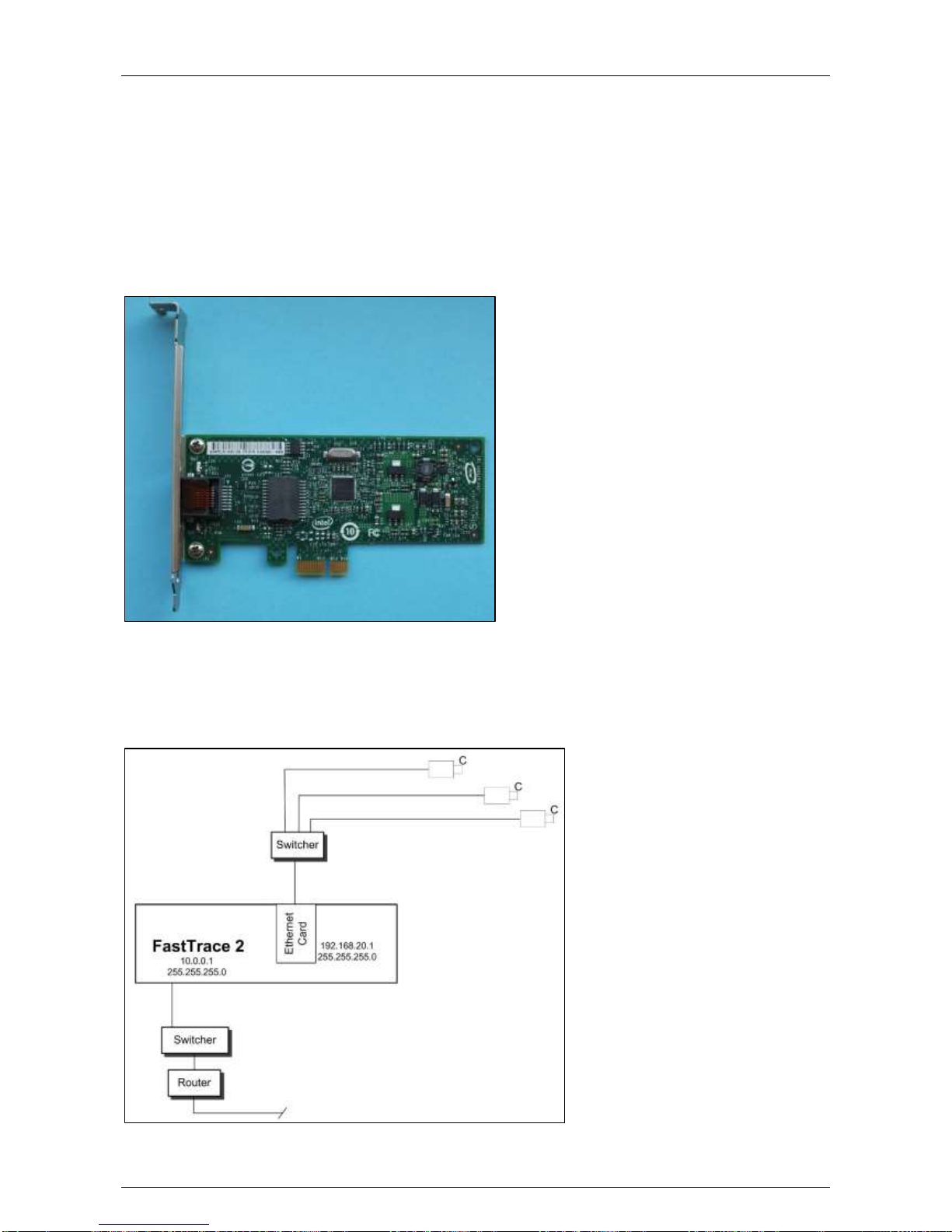
Hardware Installation Manual ADPRO® FastTrace™ 2 Series
78 21790_05
12 Ethernet Card
12.1 Installation
FastTrace 2E units with Intel motherboards are standard equipped with an Ethernet card. Units with a MiTAC
motherboard do not have an Ethernet card; the motherboard contains the necessary LAN connector.
If you want to use an analogue-only system (with 2 video encoder cards) and you want to insert 2 I/O cards
sets (2 Main I/O cards and 2 Extension I/O cards), you need to take out the Ethernet card and replace it with
an I/O card. If you have a slot available (with only 1 video encoder card), you can use the available slot for
the Extension I/O 2 card.
12.2 Ethernet Settings
You must set the Ethernet connection of your FastTrace 2 video system and the Ethernet connections of the
installed Ethernet card to different IP ranges. For more information, see the XOa Client Software User
Manual.
Page 79
ADPRO® FastTrace™ 2 Series Hardware Installation Manual
21790_05 79
13 DTC Card
The DTC card offers down-the-coax PTZ control for analogue cameras. The DTC card is built in at the
factory; you cannot order it separately. It is inserted on the back of the audio/video connection board.
The DTC card requires software. You can retrieve the current software version of the DTC card in the XOa
client software. For more information, see the XOa Client Software User Manual.
Note
You can insert DTC boards in FastTrace 2E units only with maximum 16 analogue channels. If
you want to install a DTC card in a device with 20 analogue channels, then channels 17-20 will
be removed.
Page 80
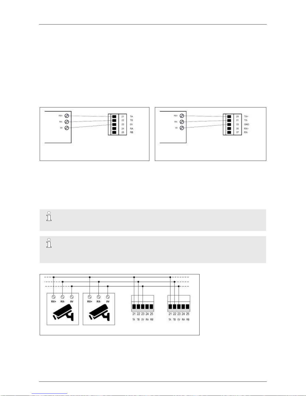
Hardware Installation Manual ADPRO® FastTrace™ 2 Series
80 21790_05
14 PTZ Cameras
You can connect PTZ (Pan-Tilt-Zoom) cameras in one of the following ways for PTZ control:
on the Main I/O card
via a USB converter
via the coaxial interface (DTC card)
Each method is described in detail below.
14.1 Serial PTZ on MIO Card
Connect the PTZ camera to the MIO card as shown below:
PTZ camera
Main I/O card
PTZ camera
Main I/O card
Next Generation
When using 5 wires to connect your PTZ camera to the Main I/O card, you also have a TX+ and TX–
terminal on the PTZ camera:
Connect the TX+ terminal to the RA terminal (number 24) of the Main I/O card, or the RX+ terminal
(number 35) on the MIO Next Generation card.
Connect the TX– terminal to the RB terminal (number 25) on the Main I/O card, or the RX– terminal
(number 37) on the MIO Next Generation card.
Note
It is recommended to terminate the last (= the longest distance from the FastTrace 2 unit) PTZ
camera with a 120 ohm resistor. RS-485 cable length: max. 1200 m.
Note
If you are connecting PTZ cameras from the same RS-485 bus to multiple FastTrace 2 servers,
set the RS-485 PTZ jumper on the Main I/O card to the 2-wire (PTZ) position.
RS-485 cable length: max. 1200 m.
PTZ cameras
Main I/O cards
Page 81
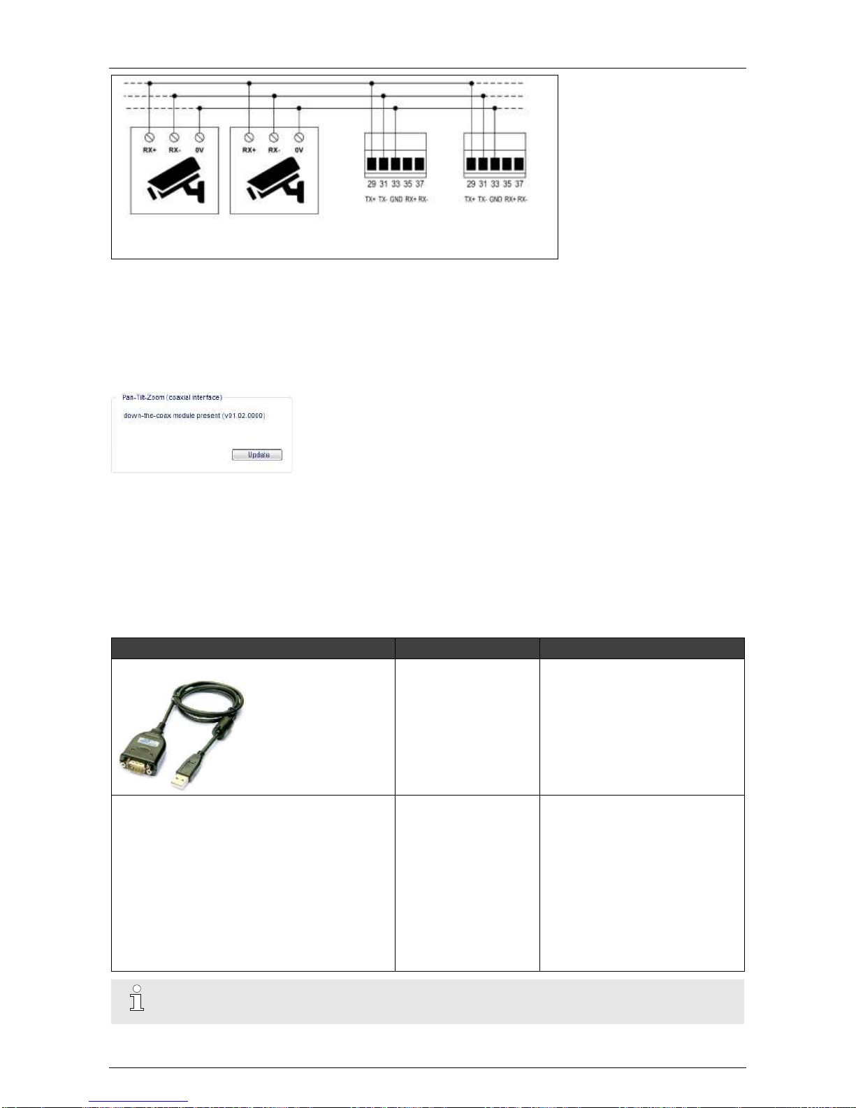
ADPRO® FastTrace™ 2 Series Hardware Installation Manual
21790_05 81
PTZ cameras
Main I/O cards Next
Generation
14.2 PTZ via DTC
Some PTZ cameras can send the PTZ signal through the coax cable. If you want to use this, you must have
your FastTrace 2 unit equipped with a DTC card. The DTC card is built in at the factory; you cannot order it
separately.
Open the PTZ window via System > Connections > Serial Ports / PTZ. Check if the DTC card is present.
The DTC card supports the following PTZ protocols:
Down-the-Coax (Pelco Ext.)
Down-the-Coax (Baxall Std.)
Down-the-Coax (Baxall Alt.)
Down-the-Coax (BBV coax)
14.3 PTZ via USB Converters
Device
Reference Number
Pin Assignment
USB to RS-485 converter
20415490
RS-485 pin assignment
(DB9 male connector)
1 = 485–
2 = 485+
5 = GND
USB to RS-232 converter
RS-232 is only used on some PTZ cameras
(such as the Philips G3 Autodome camera).
Limit the cable length to 50 ft (± 15 m). If more
than 50 ft (15 m), keep the cable capacitance
below 2500 pF.
(pF = picofarad)
20415510
RS-232 pin assignment
(DB9 male connector)
1 = Received Line Signal Detect
2 = Received Data
3 = Transmitted Data
4 = DTE Ready
5 = Signal Ground
6 = DCE Ready
7 = Request to Send
8 = Clear to Send
9 = DCE Ready
Note
You need to reboot the server after connecting the converter.
Page 82
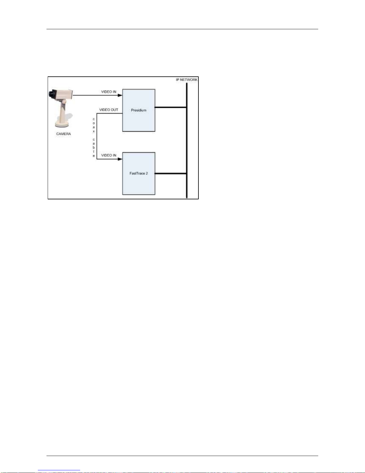
Hardware Installation Manual ADPRO® FastTrace™ 2 Series
82 21790_05
15 Presidium
You can associate video outputs from a Presidium with FastTrace 2 analogue inputs. Use coax cables to
connect the video outputs of the Presidium system to the video inputs of the FastTrace 2 video system for
further analysis and recording. It is then possible to transmit alarms from the Presidium to the FastTrace 2
server over the IP network.
See also the XOa Client Software User Manual.
Page 83
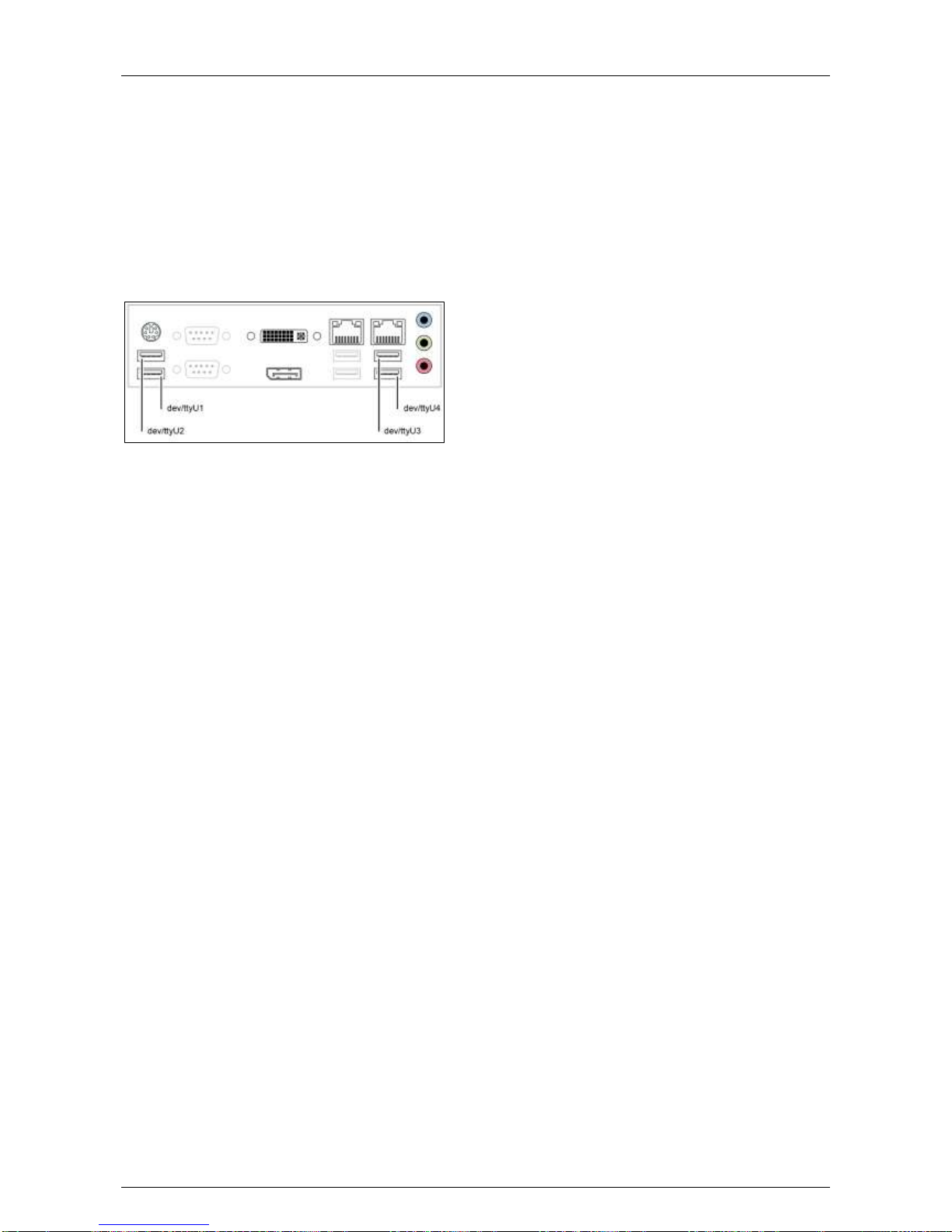
ADPRO® FastTrace™ 2 Series Hardware Installation Manual
21790_05 83
16 Modems
You can connect one modem to your server.
Normally, you connect a classic PSTN (ISDN) modem with serial port to the server by means of the USB to
RS-232 converter. This USB to RS-232 converter needs a specific FTDI chip.
The Stollman TA+USBA is the only ISDN modem with USB interface that is supported on the FastTrace 2
unit (without having to use the converter).
Connect the modem to the USB input 1 /dev/ttyU1 on the server (rear connections).
Consult the specifications of the motherboard in your unit to know which USB input to use. The example
below is for the MiTAC PH10LU motherboard.
Restart the XOa client software before configuring the modem. For more information, see the XOa Client
Software User Manual.
Page 84
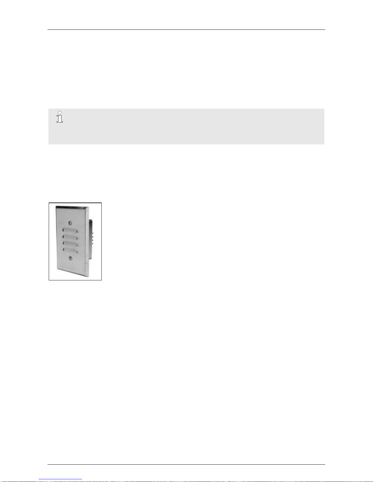
Hardware Installation Manual ADPRO® FastTrace™ 2 Series
84 21790_05
17 Audio
Not only video images can be used in the Live Video screen, also audio – both in and out – is possible.
17.1 Audio IN
17.1.1 Setup
For cameras with an audio input, you can choose to record audio and listen to audio in the live view.
Note
If the connection bandwidth is low, it is recommended to disable live audio streaming.
Audio IN is unbalanced audio.
Changing the audio settings requires a system restart.
To set up audio for the cameras, see the XOa Client Software User Manual.
17.1.2 Recommended Microphones
These microphones have been tested and approved.
17.1.2.1 Crown All-Weather PZM-11LLWR
Specifications
Technology: electret condenser
Designed for outdoor use: -10 to +60 °C
Power supply: 12–24 VAC or DC
Current consumption: 4 mA
Dimensions: 11.5 x 7 x 4.4 mm
Page 85
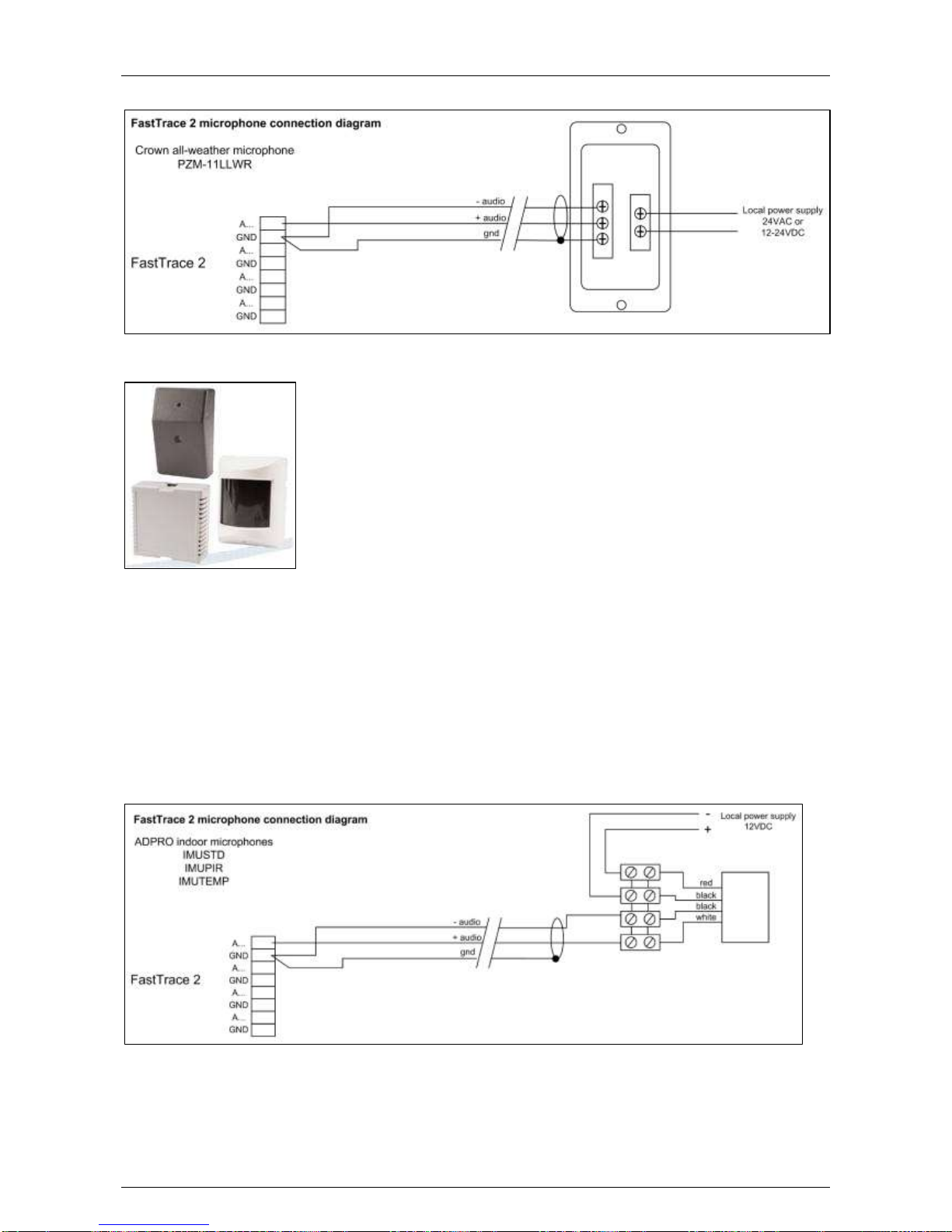
ADPRO® FastTrace™ 2 Series Hardware Installation Manual
21790_05 85
Wiring Diagram
17.1.2.2 ADPRO Microphones IMUSTD, IMUPIR, IMUTEMP
Specifications
IMUSTD = standard microphone
IMUPIR = microphone with PIR detector appearance
IMUTEMP = microphone with heat detector appearance
Designed for indoor use
Power supply: 12 VDC from regulated power supply
Current consumption: 200–400 mA
Wiring Diagram
Page 86
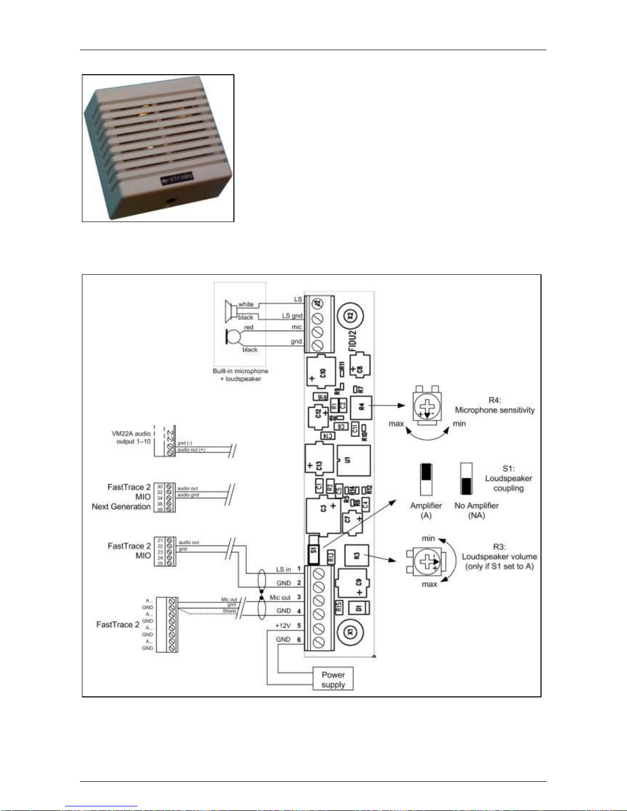
Hardware Installation Manual ADPRO® FastTrace™ 2 Series
86 21790_05
17.1.2.3 ADPRO Audio Unit
For more information, see the ADPRO Audio Unit Technical Datasheet.
Wiring Diagram
Page 87
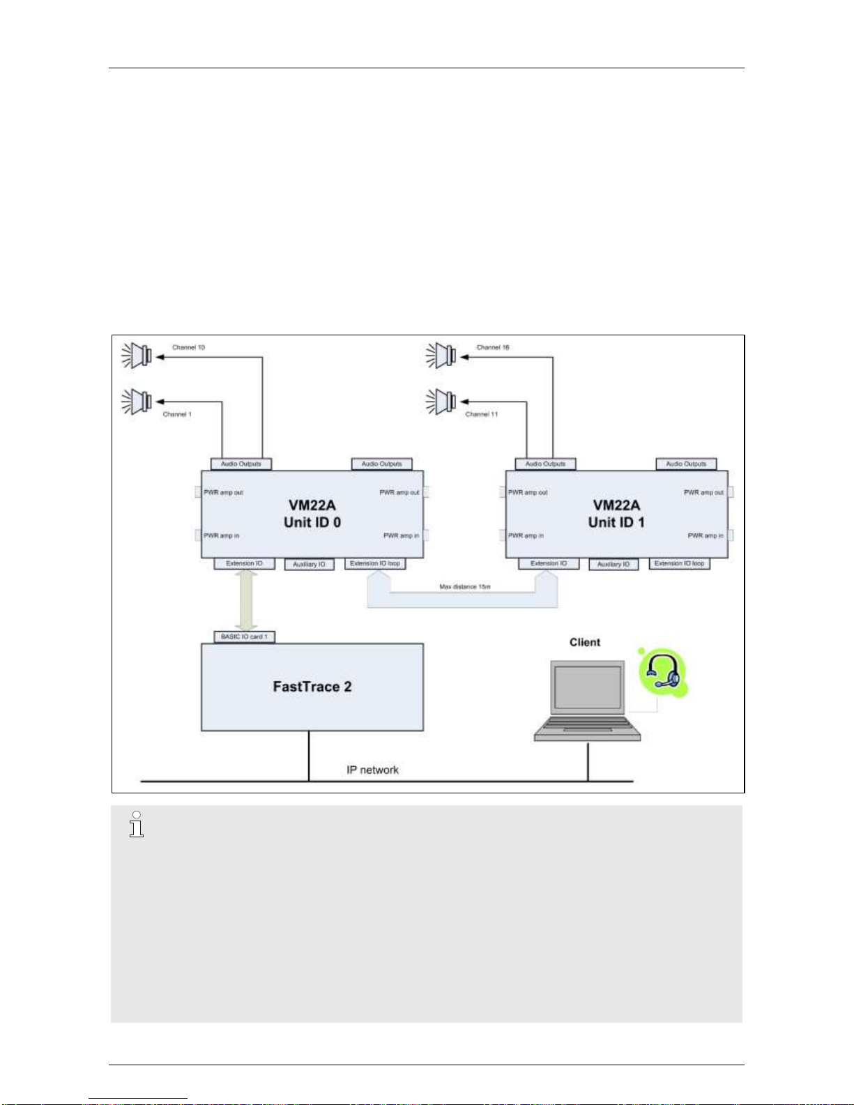
ADPRO® FastTrace™ 2 Series Hardware Installation Manual
21790_05 87
17.2 Audio OUT
17.2.1 Setup
There is one general audio output available on the server: either via the MIO or via the audio out plug of the
motherboard (= green 3.5 mm jack). If necessary, you can add VM22A audio units.
Audio outputs are available on one or two VM22A units, connected in cascade. Unit 0 is controlled by the
MIO card, and drives loudspeakers 1 to 10. Unit 1 connects to the first unit through the EIO loop connecter
and drives loudspeakers 11 to 20.
For more information, see the VM22A Audio Switcher – Installation and User Manual.
You can assign each loudspeaker to a camera using the XOa client software.
If only 1 loudspeaker is needed on the site, you can do without the VM22A switch. In this case, connect an
amplified loudspeaker to the audio out plug of the motherboard (= green 3.5 mm jack). It is also possible to
connect an amplified loudspeaker to the audio out output on the Main I/O Card.
Note
If talk-back does not work, check the following:
Routers may block UDP packets. Use TCP or configure the router to allow UDP packets.
Use the PC headphones plug instead of the PC microphone plug.
The microphone on your computer is not correctly configured.
In this case you need to configure the microphone device.
In Windows XP:
1. In Control Panel, select Sound and Audio Devices.
2. Open the Voice tab in the Sounds and Audio Devices Properties dialog box.
3. Check whether the default device is the device you want to use.
Page 88
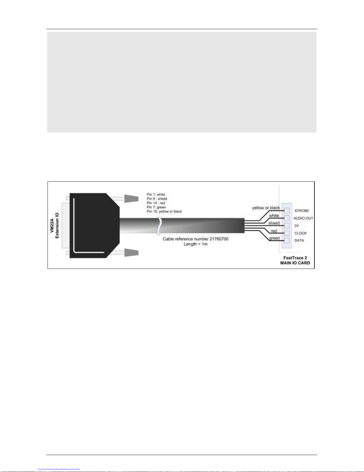
Hardware Installation Manual ADPRO® FastTrace™ 2 Series
88 21790_05
4. Click the Volume button under the Voice recording heading.
5. Adjust the vertical volume slide on the Mic volume or Line volume, depending on which
device you are using.
6. Click OK and close the Control Panel.
7. Test with Sound Recorder.
In Windows Vista / Windows 7:
1. Open Control Panel and click Hardware and Sound.
2. Open the Recording tab in the Sound window.
3. Right-click the microphone device you plugged in and select the Set as default device
option.
4. To test if it works, tap the microphone with your finger a few times. In the Sounds
window, the empty lines next to the default microphone light up in green.
17.2.2 Connecting the VM22A Audio Switch
A specific cable is used to connect the VM22A to the server.
On the back of the server, locate the MIO card. Connect the cable to the MIO as illustrated below. Respect
the colour code (yellow = STROBE; white = AUDIO OUT, shield = 0V, red = CLOCK, and green = DATA).
Page 89
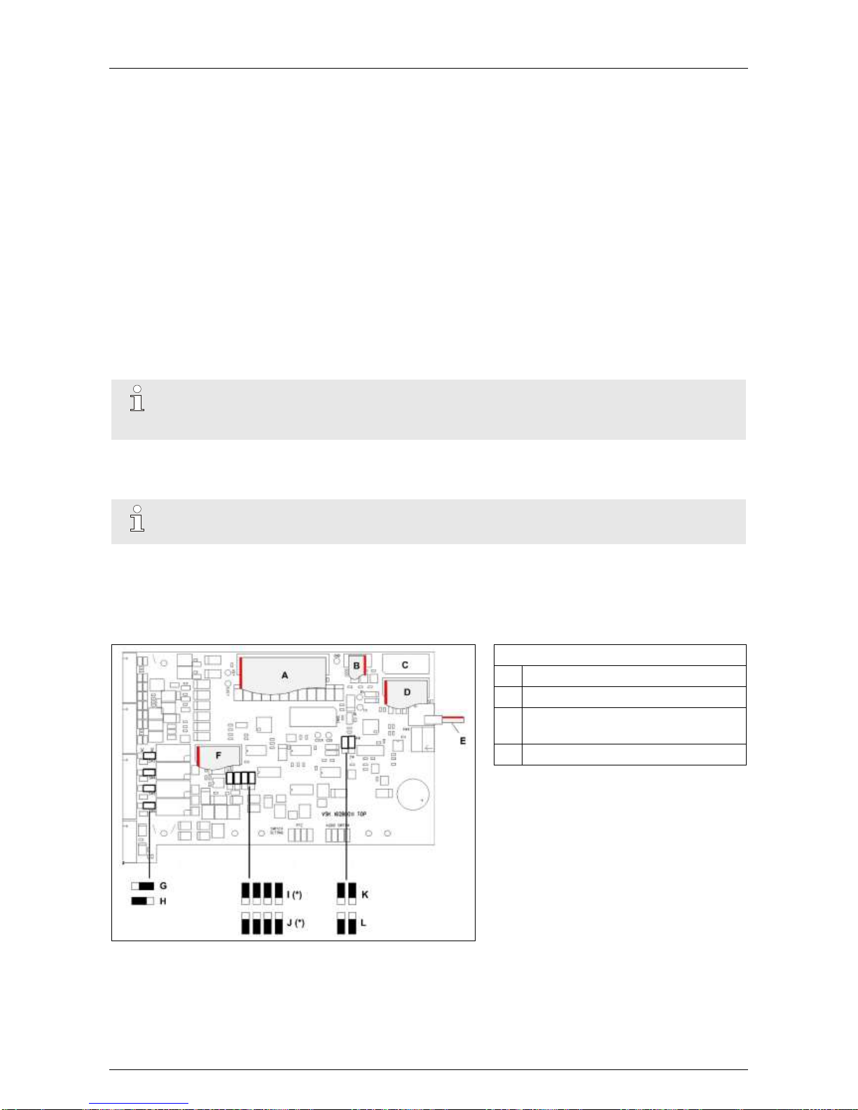
ADPRO® FastTrace™ 2 Series Hardware Installation Manual
21790_05 89
18 Connecting PIRs
18.1 Required PIR Firmware
For a correct functioning of the PIR alarm processing, a minimal PIR firmware version 2.00 is required.
Previous firmware versions also work with RS-485 communication, but do not support all features (e.g. Alarm
Management).
18.2 Connecting the PIRs
To connect PIRs to the server, you have the following options:
using an RS-485 cable and connecting the cable from the PIR to the Main I/O card of the server
using the USB to RS-485 8 channel distribution unit
using a USB to serial port RS-485 converter and connecting the PIR to the converter by means of an
RS-485 cable
Note
From firmware version 2.6 onwards, a separate PIR-HLI application license is required to
configure the PIR devices.
18.2.1 Connecting the PIR Detector Directly to the Main I/O Card
Note
For the Next Generation Main I/O cards, see Main I/O Cards Next Generation on page 90.
Connect the PIR device(s) (set up multiple PIRs in cascade) to the server by connecting the RS-485 cable of
the PIR closest to the server to the Main I/O card.
You must connect the PIR(s) to the appropriate terminals on the Main I/O card.
Set the jumpers on the Main I/O to PTZ output and RS-485 2-wire.
MIO card Next Generation
I Jumper setting: PTZ output (*)
J Jumper setting: VM22A output (*)
K RS-485 PTZ jumper: 4-wire setting
(default setting)
L RS-485 PTZ jumper: 2-wire setting
(*) PTZ/VM22A:
On 1st Main I/O: addressed as
/dev/ttyU6.
On 2nd Main I/O: addressed as
/dev/ttyU8
Also bridge the following connections:
TA (pin 21) with RA (pin 24)
TB (pin 22) with RB (pin 25)
Page 90
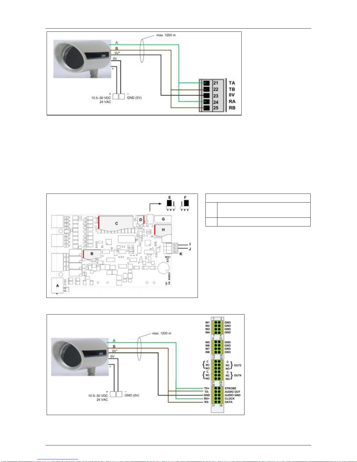
Hardware Installation Manual ADPRO® FastTrace™ 2 Series
90 21790_05
(*) Some PIR models have separate 0V terminals for data and power; on other models there is only one
common 0V terminal.
The PIRs are powered locally by a power adapter.
You can place locally powered PIR detectors at the maximum distance of 1200 m for RS-485 cables, but
remember that this remains a 3-line communication (RS-485 + 0V).
Make sure that there is no difference in earth potential between the server and the PIR.
18.2.1.1 Main I/O Cards Next Generation
On the MIO card Next Generation, all connectors are available, so you do not need to adjust any jumpers to
choose between PTZ and audio output. Set the RS-485 PTZ jumper to the 2-wire (PTZ) position.
MIO card Next Generation
E RS-485 PTZ jumper: 4-wire setting
(default setting)
F RS-485 PTZ jumper: 2-wire setting
Connect the cables as shown below.
Page 91
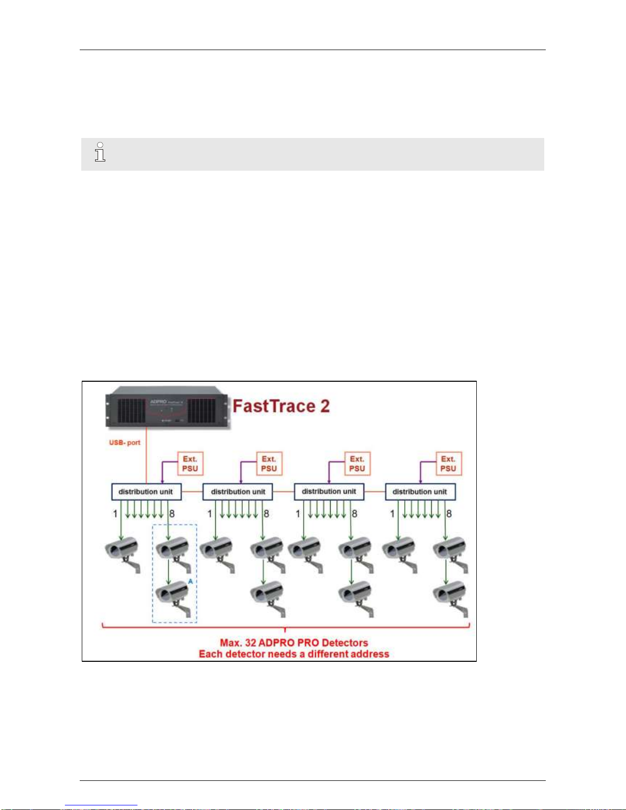
ADPRO® FastTrace™ 2 Series Hardware Installation Manual
21790_05 91
(*) Some PIR models have separate 0V terminals for data and power; on other models there is only one
common 0V terminal.
The PIRs are powered locally by a power adapter.
You can place locally powered PIR detectors at the maximum distance of 1200 m for RS-485 cables, but
remember that this remains a 3-line communication (RS-485 + 0V).
Make sure that there is no difference in earth potential between the server and the PIR.
Note
If you use a 24 VAC supply for more than 1 PIR, make sure to connect all PIRs in phase.
18.2.2 Connecting the PIR Detector Using the USB to RS-485 8-Channel
Distribution Unit
The USB to RS-485 distribution unit provides 8 channels (1 PIR unit per channel) to easily connect and
configure the PIR units to the server.
For more information, see technical datasheet 19532060 on the USB to RS-485 8-channel distribution unit.
Up to 8 PIRs can be connected through star wiring to the USB to RS-485 distribution unit. Only the 485
bidirectional communication of the PIRs is used, we do not use the mechanical PIR tampers. It is possible to
connect 4 distribution units in cascade (= only one of the 4 distribution units needs to be connected to the
server, but the cables between the other units shall not exceed 1 metre), so the server supports a maximum
of 32 PIR devices.
The distribution unit contains a USB connection port for communication with the server. Connect it to the
dev/ttyU2 USB port on the server. Do not use any other ports. Keep the USB cable between distribution unit
and server as short as possible (max. 1 metre).
Restart the XOa client software after connecting the PIR to the USB port.
Page 92
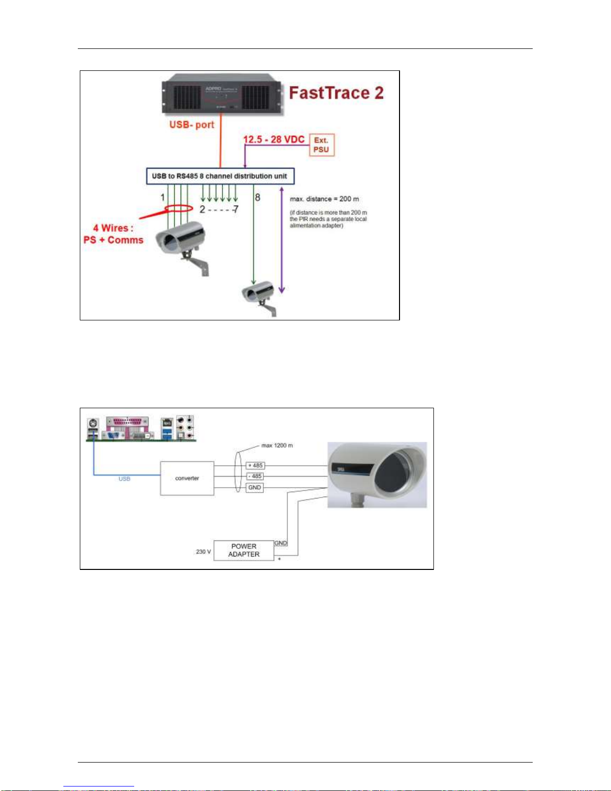
Hardware Installation Manual ADPRO® FastTrace™ 2 Series
92 21790_05
A detailed view of one connected distribution unit:
18.2.3 Connecting the PIR Detector Using a USB to Serial Port RS-485
Converter
Connect the PIR detector to the converter and plug the USB cable of the converter in the dev/ttyU2 USB port
of the server.
Restart the XOa client software after connecting the PIR to the USB port.
You can place locally powered PIR detectors at the maximum distance of 1200 m for RS-485 cables, but
remember that this remains a 3-line communication (RS-485 + 0V).
Make sure that there is no difference in earth potential between the server and the PIR.
The above drawing shows you the Intel DH61BE motherboard. For the location of dev/ttyU2 USB port on the
specific motherboard of your video system, see Required Motherboard on page 32.
Page 93
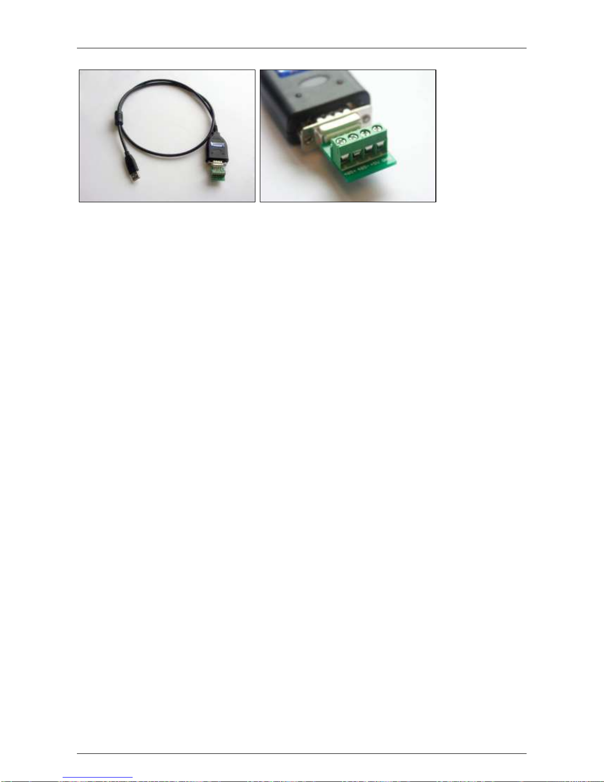
ADPRO® FastTrace™ 2 Series Hardware Installation Manual
21790_05 93
You need to order the USB to serial port RS-485 converter separately (reference number 20415490).
Page 94
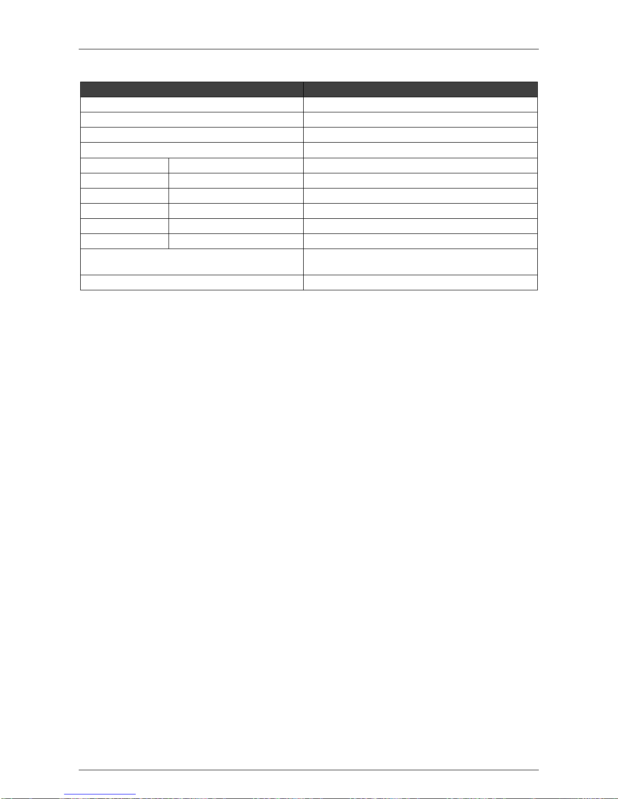
Hardware Installation Manual ADPRO® FastTrace™ 2 Series
94 21790_05
19 Network Load
Application
Bandwidth volume
Alarm transmission
Negligible
Remote control (executing commands)
Negligible
Software update
Volume of about 170 MB
Configuration update
Volume of 150 kB
Video streaming
4CIF / 25 ips
400 kbps / camera
4CIF / 6 ips
140 kbps / camera
CIF / 25 ips
80 kbps / camera
CIF / 6 ips
43 kbps / camera
QCIF / 25 ips
17 kbps / camera
QCIF / 6 ips
6 kbps / camera
Audio in
16 kbps / camera (with DS40xx cards)
64 kbps / camera (with DS42xx cards)
Audio out
8 kbps
Video streaming H.264, VBR, and quality set to medium.
Page 95
ADPRO® FastTrace™ 2 Series Hardware Installation Manual
21790_05 95
20 Current Consumption
Estimated current consumption depends on the installed components and on the system load:
Motherboard
16 W (Intel)
Processor
25 W (AMD)
Intel DG31, DG41: 65 W max.
Intel DH55: 73 W max.
Intel DH61: 77 W max.
4 channel A/V card
3.5 W
8 channel A/V card
7 W
Western digital RE hard disk
11 W
Western digital RE2 hard disk
12 W
Main I/O card
1 W
Extension I/O card
1 W
HIPI card (for IP cameras)
3 W
DTC card (“Down the Coax”)
0.5 W
Example (with maximum values):
Motherboard
16 W
Processor
77 W (DH61BE with Core i7 microprocessor)
Two 8-channels A/V cards
14 W
4 Western Digital RE2 hard disks
48 W
Main I/O card
1 W
Extension I/O card
1 W
TOTAL
on secondary circuit
on primary circuit (total current consumption
divided by 0.8 – this is the efficiency of the
power supply)
157 W
196 W (0.80 A / 230 VAC)
Note
Measurement on a fully equipped (*) FastTrace 2 server (with DH61BE motherboard and G850
microprocessor) produced the following results: 0.41 A at 230 VAC 95 W (idle state).
(*) Fully equipped = FastTrace 2 server with 2 Main I/O cards, 1 Extension I/O card, 1 HIPI
card, two 8-channel A/V cards, and 4 hard disks (2 TB per disk).
Page 96

Hardware Installation Manual ADPRO® FastTrace™ 2 Series
96 21790_05
21 Retrieving the IP Address
Connect a monitor/screen and keyboard to the server. If the video matrix is active, press Ctrl+Alt+F1.
The welcome screen appears:
Video Security FastTrace 2E (XOa V3.00.003)
Ip: 10.0.0.10
Subnet: 255.255.255.0
Gateway: 10.0.0.1
The welcome screen displays the following information:
Server model and software version
IP address, subnet mask, and gateway.
Page 97
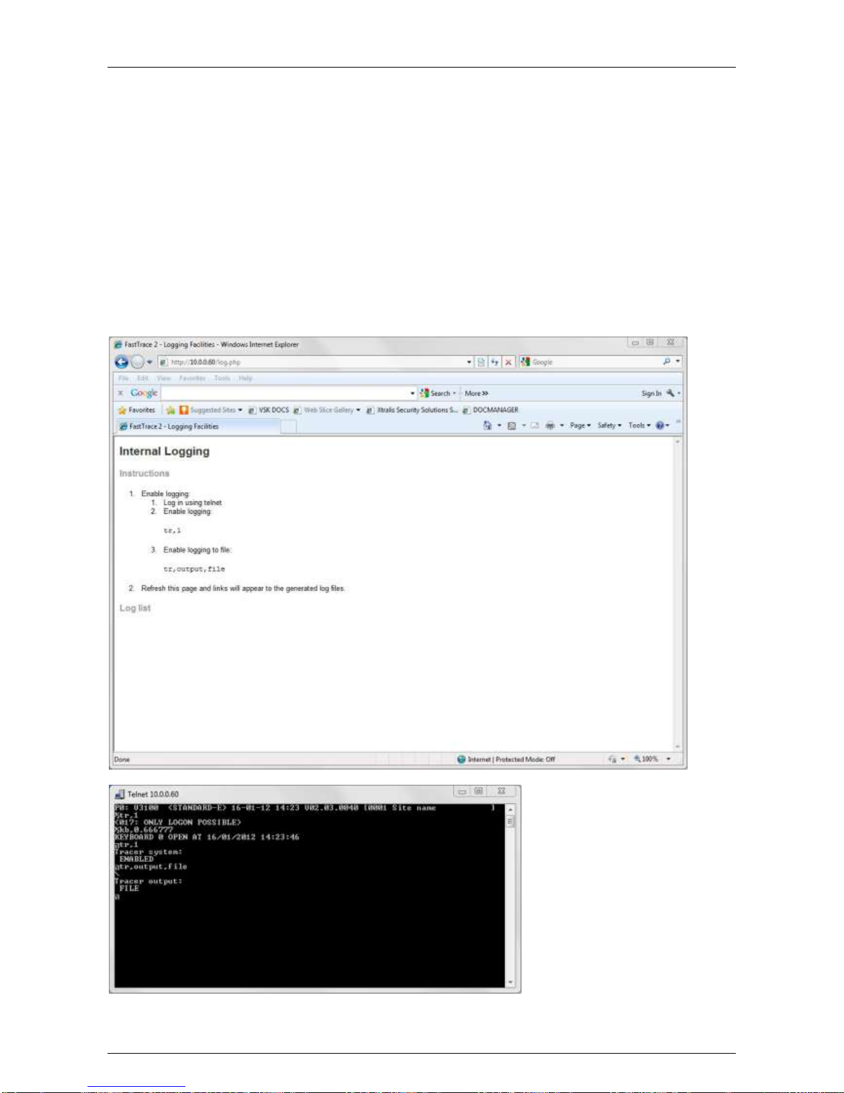
ADPRO® FastTrace™ 2 Series Hardware Installation Manual
21790_05 97
22 Diagnostics
In case of major troubles with the server, the system allows to generate a number of traces. In some cases,
the Xtralis Support Division may ask you to activate and capture some traces and files that can be helpful to
resolve any technical issues.
22.1 Retrieving Traces
The server can output its internal trace buffer to hard disk to allow tracing for longer periods of time without
losing the data. This happens with the Telnet command tr,output,file. To easily retrieve these files, type the
server’s IP address in the address bar of your internet browser and add /log.php to the address.
Example: http://10.0.0.10/log.php.
Here you can download the generated log files. You need to enable logging first.
When you open the web page without having enabled logging, the Internal Logging page appears. It
displays the instructions to enable logging.
Page 98
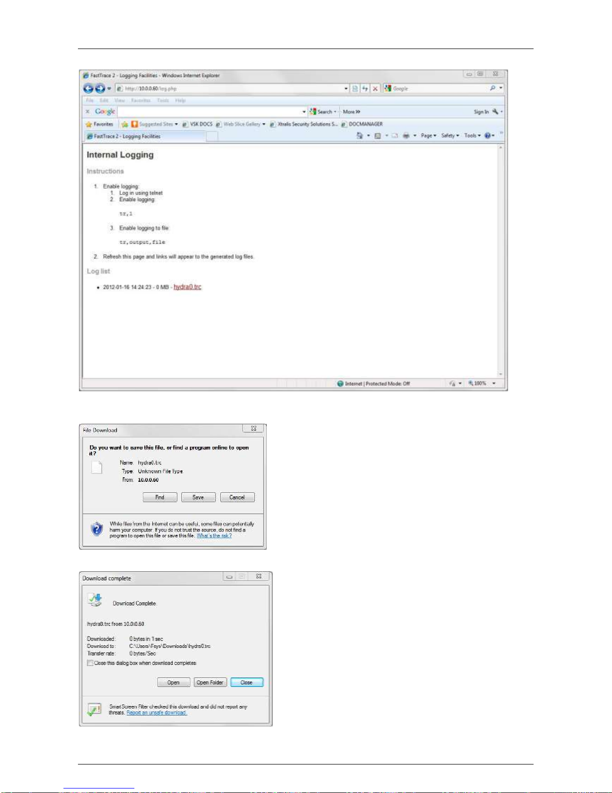
Hardware Installation Manual ADPRO® FastTrace™ 2 Series
98 21790_05
Click the link on the web page.
Click Save to store the file on your PC or a network folder. Do not try to find a program online, because this
will provide unexpected websites.
Click Open and choose Notepad as the default application.
Page 99
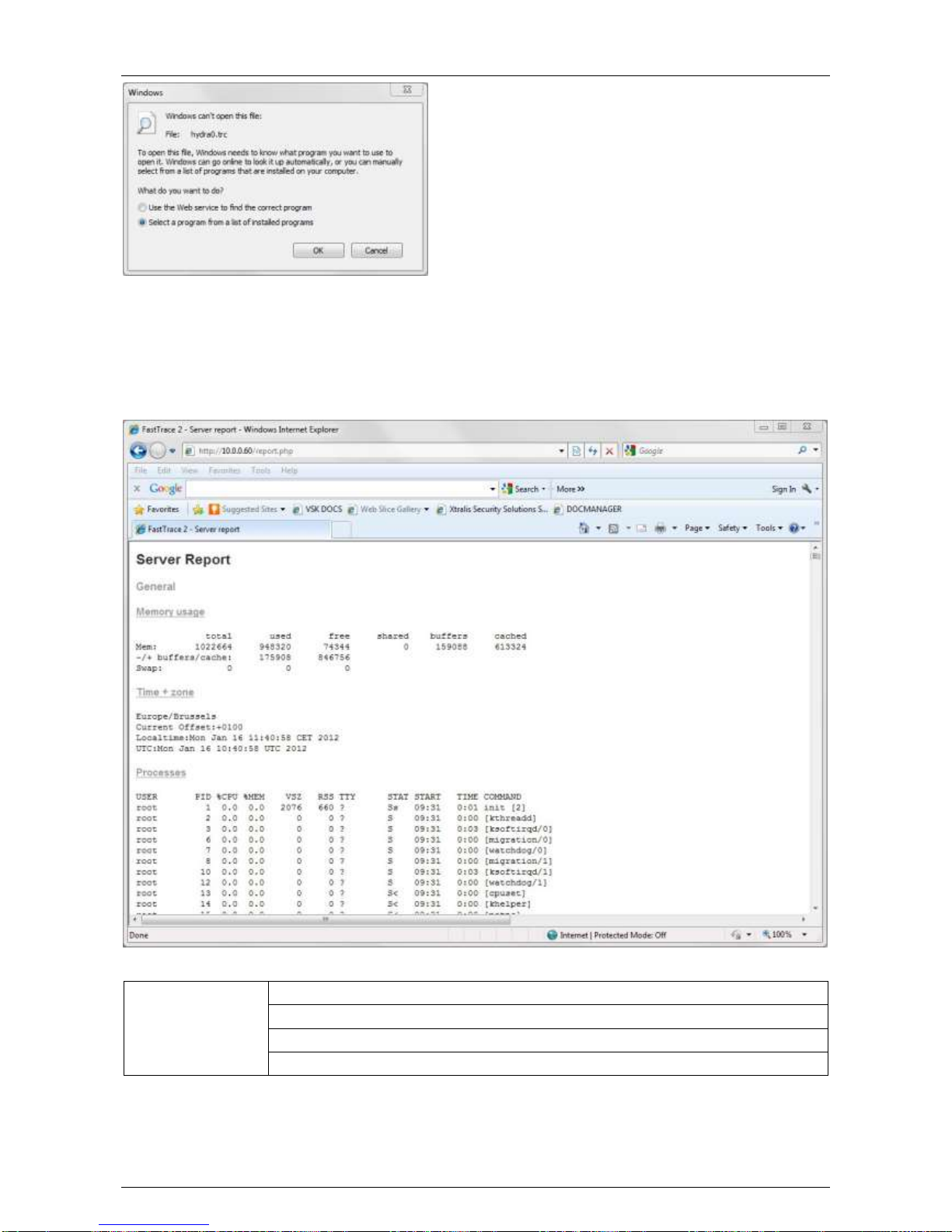
ADPRO® FastTrace™ 2 Series Hardware Installation Manual
21790_05 99
22.2 Retrieving Reports
The server generates a number of reports. You can view these reports via the internet browser. Type the IP
address of the server in the address bar of the browser and add /report.php to the IP address.
Example: http://10.0.0.10/report.php
The Server Report shows the following items:
General
Memory usage
Time + zone
Processes
Uptime
Page 100

Hardware Installation Manual ADPRO® FastTrace™ 2 Series
100 21790_05
Performance
Vmstat
I/O stat
PID stat
MP stat
Network
Interfaces – available
Interfaces – enabled
Routes
Listen ports
Netstat – all
DEV stats
Sockstat
ARP cache
Filesystem
Mounts
S.M.A.R.T
Fsck
Open files
Free disk space
Hardware
CPU
Memory
Mainboard
PCI
Udev database
Server
Server version
Server process memory usage
Files
Active config
Contact the Xtralis Support Division for further assistance.
 Loading...