

Page 1
Quick Setup Guide
201335.06 Page 1 Vision Fire & Security
A
DPRO
®
FastTrace™
Use this guide for the first-time setup of the ADPRO FastTrace Remote Access DVR.
The setup procedure is the same for 5-channel, 10-channel and 20-channel models.
Unpack the ADPRO FastTrace and check for signs of damage. If any damage is found, before installation please report
to your supplier or to Vision Fire & Security directly.
Check the carton contents:
• ADPRO FastTrace
• CD-ROM containing ADPRO FastTrace PC Viewer Software
• Installation and Setup Manual
• Null-modem cable 1m (3ft)
• 9-way screw terminal plug
• 4x 15-way screw terminal plugs (6 supplied with Model 5020)
• IEC power cord
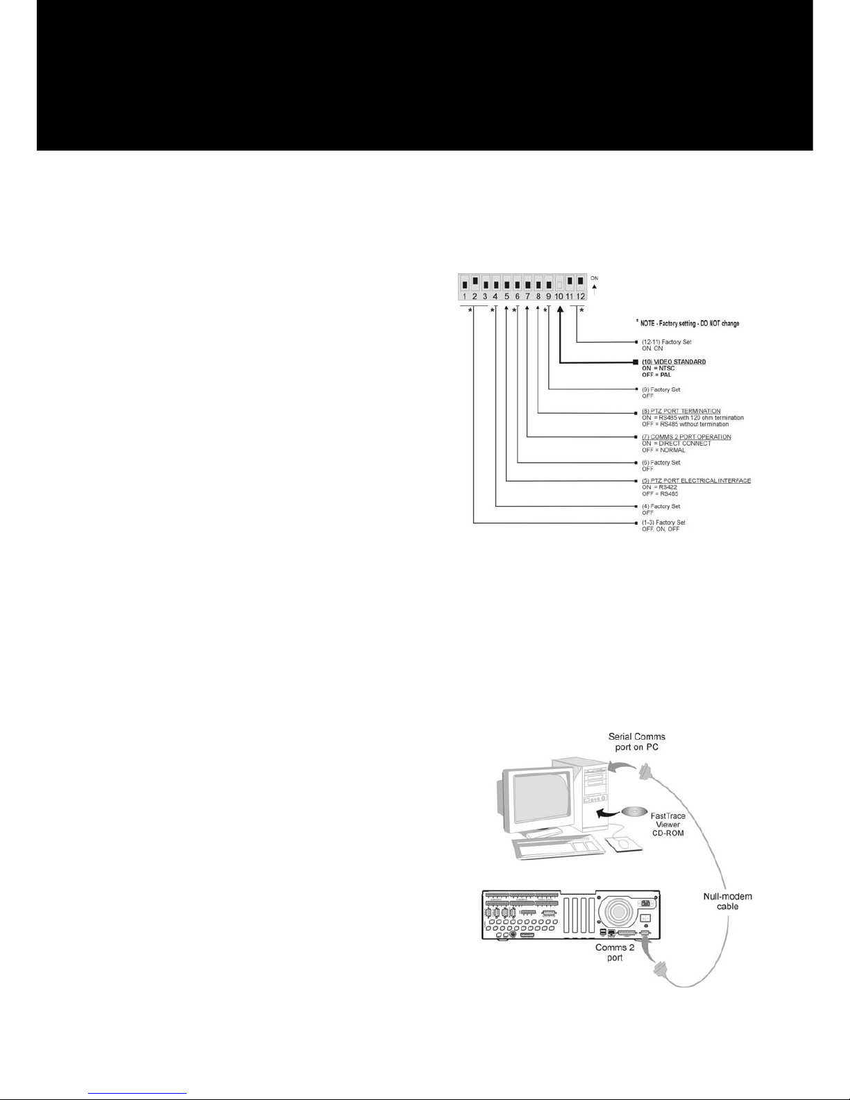
CHECK FACTORY DIPSWITCH SETTINGS AS SHOWN
Make sure that the unit is set to operate to the appropriate video
standard for the region, either PAL or NTSC (check DI Pswitch
10 for correct position).
To complete the first time setup, you will need a PC running
Windows NT or Windows 2000, with an unused serial port or an
Ethernet Port and a CD-ROM drive.
Installing FastTrace PC Viewer Program:
Start the PC and insert the ADPRO FastTrace PC Viewer CD-ROM. If the 'autorun' feature is used, the ADPRO
FastTrace PC Viewer setup wizard will load. If autorun is not enabled, find and run the CD-ROM file named
cdmenu.exe.
Select the Install FastTrace PC Viewer option. Follow the setup wizard instructions and accept ALL the default settings.
Exit from the menu when finished, but leave the CD-ROM in the drive.
NOTE: If using the Windows NT system on the PC, please refer to the IMPORTANT NOTES section on Page 4.
Configuring the FastTrace PC Viewer & FastTrace:
The FastTrace's User Settings menu is accessed by the FastTrace PC Viewer software. Access can be made in two
ways, via the PC's serial (comms) port or via the network port.
Using the Serial Port to access FastTrace:
When using serial port connection, the 1m (3ft) null-modem cable
(supplied) is used. (Note: should a longer cable be required, the
wiring diagram is shown on Page 3 of this guide).
• The serial comms (COM) port on the PC must be configured for
operation as follows:
Data rate = 115,200 bps, Data bits = 8, Parity = none, Stop-bits
= 1, Flow control = hardware
Note: To change the settings on the COM ‘n’ port, go to:
Windows NT: Control Panel / Ports / COM 'n'
Windows 2000: Control Panel / System /
Hardware / Device Manager /
Ports / COM 'n' / Port Settings
• Ensure the FastTrace is free-standing with no obstruction to
airflow (cooling fan at rear)
• Connect the cable between the FastTrace "COMMS 2" port and
the PC’s serial port (see diagram)
Page 2

ADPRO FastTrace - Qui ck Setup Guid e
201335.06 Page 2 Vision Fire & Security
• Note that for the serial port t o operate correctly, a special ‘null-modem’ software driver needs to be installed. To
install this driver, go to (Windows NT): Start/Settings/Control Panel/Modems and select the Add option.
If using Windows 2000: Control Panel/Phone & Modem options/Modems and select the Add option. When the Install
New Modem dialog box is displayed, click the Don't detect my modem, I will select it from a list checkbox, then
click Next
• Click the Have Disk button to find the software driver file at: CDdrive#:/install/mdmcisc2.inf (note that the CD-
ROM should still be in the drive)
• Click OK - the driver software should now load
• Re-boot the PC to ensure the serial comms and modem driver changes become active
To start the FastTrace PC Viewer program, double-click the FastTrace icon .
Accessing FastTrace for the first time:
To hel p users with the first time setup, a number of default setti ngs are used in the ADPRO PC Viewer software that
must match the default factory settings found in a new FastTrace unit.
The default settings stored in the FastTrace PC Viewer for a serial port connection can be found by using the following
link: Database/Administration/OK/Configure Sites. To check the defaults, select the "FastTrace default site" entry and
click Edit. The default values are shown below:
Site ID = FASTRACE
Name = FastTrace default site
Password = FT2222
Connection Type = PSTN
Transmitter type = FastTrace
Hunt Group = Hunt Group 0
Phone (number) = 0
Optional Network Connection Settings:
If using the PC's network port (instead of the serial port), a ‘crossover’ network cable (Cat 5) must be used between the
PC and the FastTrace. (Not e: this cable NOT supplied).
• The (factory) TCP/IP network address for the FastTrace is: 192.168.1.1
• The (factory) subnet mask address is 255.255.255.0
To use the network connection, change the Site Configuration settings (Database / Administration / OK / Configure
Sites) in the ADPRO FastTrace PC Viewer to the following:
• Connection Type = Network
• IP Address = 192.168.1.1
Before exiting the System Administration, select Configure Communications and follow the wizard to de-select the
Generic Null Modem and select the Network Adaptor.
Configuration of your PC IP properties are needed to ensure the network address and subnet mask will allow
communication with the FastTrace.
The (factory) TCP/IP network address and subnet mask for the FastTrace are class C addresses. For the PC to be able
to successfully connect to the FastTrace, your PC IP settings will also need to be modified to a class C address.
For ease of initial setup, you must change the PC IP settings to the following:
• The TCP/IP network address for your PC should be set to: 192.168.1.2
• The subnet mask address should be set to: 255.255.255.0
Connecting to the FastTrace:
Ensure the FastTrace has completed its start-up checks (as indicated by the red status light going off).
• From the Connection menu, click the Connect to Site option
• Select the site named FastTrace default site and click the OK button
Page 3
ADPRO FastTrace - Qui ck Setup Guid e
201335.06 Page 3 Vision Fire & Security
Accessing the FastTrace 'User Settings' menu:
Setup parameters and configuration options for the FastTrace can now be modified via the User Settings menu. To
display the menu:
• Go to the Connection menu and click the Installer Menu option
For a new FastTrace, a message will appear asking the user to accept the Factory Default settings.
Click YES to this question.
The menu consists of a number of major categories, some with a number of sub-categories and option choices.
Selection of a particular category can be expanded by double-clicking on the menu item.
Once the configuration is complete, all changes can be saved using the Save all changes button. When saved, the
changes are downloaded to the FastTrace memory for permanent storage.
NOTE: The setup program will not allow invalid parameters to be saved. For example, should you receive a message
asking for a correct Ethernet Gateway address to be entered, either enter the correct value or delete the invalid entry.
Setting the Operational Parameters:
The FastTrace is factory configured with ‘typi cal’ operating
values, but to use the FastTrace in an operational
environment, it's configuration must be modified to use the
site names, phone numbers or network addresses that match
the real network.
Once the FastTrace settings have been configured, the
ADPRO FastTrace PC Viewer settings must be updated to
match.
Setting the ADPRO FastTrace PC Viewer Telephone
(Dial-up) Connection
The basic information needed to use a telephone (dial-up)
connection is entered via the Database / Administration /
Site Details menu:
Site ID 9 characters (max)
Password 8 characters (max)
Modem Type Select from the list (Note
different modem types must
be installed via the Windows
Control Panel)
PC Viewer Settings for a Network Connection
The ADPRO FastTrace PC Viewer software will require some basic information in order to connect to any FastTrace site
via a network connection. The minimum information that must be configured in each FastTrace is shown below.
To enter the information, go to Database / Administration / Site Details then select the Edit option.
Site ID 9 characters (max)
Password 8 characters (max)
IP Address The TCP/IP network address assigned to each FastTrace (this address is normally assigned by
the network manager)
Once the basic connection details have been configured and
saved, the FastTrace is ready to connect via the operational
network.
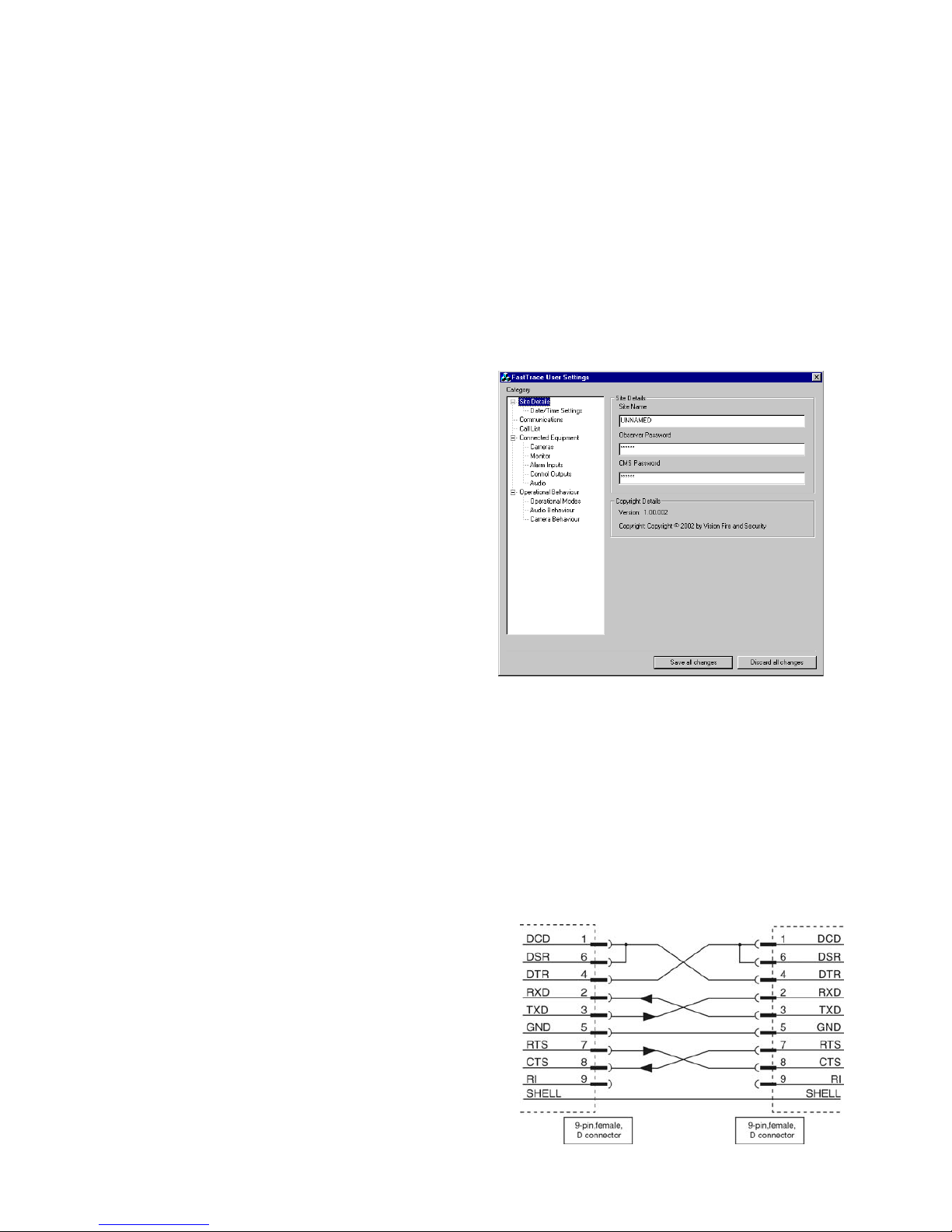
Null-modem cable wiring:
Should it be necessary to use a null-modem cable that is longer
than that supplied with the FastTrace, use the diagram shown to
make a longer cable.
Page 4

ADPRO FastTrace - Qui ck Setup Guid e
Asia / Pacific
Vision Fire & Security
Private Bag 215
495 Blackburn Road
Mount Waverley Vic 3149
Australia
Ph +61 3 9211 7300
Fax +61 3 9211 7202
Toll Free 1800 700 203
The Americas
Vision Fire & Security
700 Longwater Drive
Norwell Massachusetts 02061 USA
Ph +1 781 740 2223
Fax +1 781 740 4433
Toll Free 800 229 4434
Europe & the Middle East
Vision Fire & Security
Vision House
Focus 31, Mark Road
Hemel Hempstead Herts HP2 7BW UK
Ph +44 (0) 1442 242 330
Fax +44 (0) 1442 249 327
Web Site
http://www.adpro.com.au
The manufacturer reserves the right to change de signs or specifications without obligation and without further
notice. ADPRO, FastTrace, FastVu, Fast Scan, Axiom, PRO, Amux and Video Central are brands and trademarks
used under licen ce by the distributor.
Printed: June 2003 P/N 201335.06
Quality
Endorsed
Company
ISO 9001:2000
Lic. QEC 2868
Troubleshooting Tips:
• Ensure that matching details entered at the FastTrace PC Viewer AND at the site equipment are IDENTICAL
• If using a serial port connection, check the port configuration in the PC is set for the correct speed and data
configuration to match the modem type used
• If using a network connection, ensure the TCP/IP address and subnet mask are correct
IMPORTANT NOTES
Setting the Date and Time:
The ADPRO FastTrace uses a stable internal clock that is based on UCT (Universal Coordinated Time). Date and time
settings of the unit operate in a way that is similar to a PC and a 'Time Zone' value is provided in the Date / Time
Settings option of the Site Details menu.
To ensure correct operation, the Time Zone value should be configured prior to any date or time changes being made.
Windows NT on the PC
When Windows NT is used as the PC's operating system and a serial connection to the FastTrace is used, ensure that
the FastTrace PC Viewer software is running BEFORE the FastTrace is powered up. Correct connection will then occur.
After the first connection has been made and other re-connections are required (or the unit becomes disconnected for
any reason), then the serial cable must be unplugged for at least 10 seconds. This procedure will ensure that the
FastTrace stops trying to reconnect and "locking out" the correct connection attempts by the PC Viewer software.
LED Switch
When power is first applied to the FastTrace unit, the red LED on the front of the unit will be on. Within a few seconds the
red LED should start switching on, then off, every two seconds. This signifies that the unit is going through its boot cycle
and performing its internal tests. Once the unit successfully completes its boot and test sequence, the red LED will switch
off, and remain off.
If at any time during operation, the red LED switches on and stays on, this signifies a fault with the unit and technical
support is required.
Communication Settings Override:
If for any reason, the operational Site ID, password or network address for a
FastTrace is lost, use the following procedure to temporarily restore this information.
1. Set the FastTrace's DIP Switch 7 (on the rear panel) to the ‘ON’ position.
2. Re-power the unit.
This procedure will not ‘Factory Default’ the unit.
It will only set the unit to the following settings until Dip Switch 7 is turned off
and the unit is re-powered.
Site ID (FASTRACE) Password (FT2222)
Network Address (192.168.1.1) Subnet Mask (255.255.255.0)
3. Connect a crossover network cable or the null modem (serial) cable between
the unit and a PC running the ADPRO FastTrace PC Viewer.
4. Modify the ADPRO FastTrace PC Viewer settings (Database / Administration
/ Site Details) as follows:
• (NETWORK connection) - Set 'Connection Type' = Network and 'IP
Address' = 192.168.1.1
OR
• (SERIAL connection) Set ‘Connection Type’ = PSTN and
‘Phone’ = 0
5. Connect to Site (FASTRACE) using the default Password (FT2222).
6. Go the Connection menu and select the Installer Menu option to display the
FastTrace's User Settings menu.
7. Change Site Details to the new SITE ID, PASSWORD and Network Address
values.
8. SAVE ALL CHANGES when exiting the User Settings menu.
9. Reset Switch 7 to the OFF position and re-power the unit.
The FastTrace will now operate with the new Site ID, Password and Network
Address.
 Loading...