

Page 1

User Manual
11/11/2010
Page 2

GPX Pro Manual
© 2009 XT Racing
All rights reserved. No parts of this work may be reproduced in any form or by any means - graphic, electronic, or
mechanical, including photocopying, recording, taping, or information storage and retrieval systems - without the
written permission of the publisher.
Products that are referred to in this document may be either trademarks and/or registered trademarks of the
respective owners. The publisher and the author make no claim to these trademarks.
While every precaution has been taken in the preparation of this document, the publisher and the author assume no
responsibility for errors or omissions, or for damages resulting from the use of information contained in this
document or from the use of programs and source code that may accompany it. In no event shall the publisher and
the author be liable for any loss of profit or any other commercial damage caused or alleged to have been caused
directly or indirectly by this document.
Page 3

Table of Contents
IContents
Part I GPX Pro
................................................................................................................................... 11 Circuit Racing Mode
................................................................................................................................... 112 Point-to-Point Racing Mode
................................................................................................................................... 193 Drag Racing Mode
................................................................................................................................... 264 Instrument Cluster Mode
................................................................................................................................... 265 Menu System and Navigation
................................................................................................................................... 276 Switching Racing Modes
................................................................................................................................... 277 Data Acquisition (DAQ)
................................................................................................................................... 458 Time and Distance Meters
................................................................................................................................... 469 Miscellaneous Information
1
.......................................................................................................................................................... 1Basic Operation
.......................................................................................................................................................... 5More Details
.......................................................................................................................................................... 7Menus
.......................................................................................................................................................... 11Basic Operation
.......................................................................................................................................................... 13More Details
.......................................................................................................................................................... 15Menus
.......................................................................................................................................................... 20Basic Operation
.......................................................................................................................................................... 21More Details
.......................................................................................................................................................... 22Menus
.......................................................................................................................................................... 27Basic Information
......................................................................................................................................................... 31Installing Cables
......................................................................................................................................................... 31Wiring w ith Scotchlok Connectors
.......................................................................................................................................................... 32Basic DAQ Setup
.......................................................................................................................................................... 34Typical Inputs
......................................................................................................................................................... 34RPM
......................................................................................................................................................... 36Throttle Position
......................................................................................................................................................... 36Temperature
......................................................................................................................................................... 38Gear
......................................................................................................................................................... 40Acceleration
......................................................................................................................................................... 41Wheel Speed
......................................................................................................................................................... 41Suspension
......................................................................................................................................................... 42Switch Input
.......................................................................................................................................................... 43Generic Types of Inputs
......................................................................................................................................................... 430-100%
......................................................................................................................................................... 43Zero-based
......................................................................................................................................................... 44Temperature
......................................................................................................................................................... 44Raw
......................................................................................................................................................... 44Switch
.......................................................................................................................................................... 44Alarms
.......................................................................................................................................................... 44General DAQ Notes
.......................................................................................................................................................... 46Tach LCD display and LED/Shift lights
.......................................................................................................................................................... 47Session Number IDs
.......................................................................................................................................................... 48Normal / Reverse LCD Display
.......................................................................................................................................................... 48Backlight
.......................................................................................................................................................... 49Mounting
.......................................................................................................................................................... 49Time and Time Zones
© 2009 XT Racing
I
Page 4

GPX Pro ManualII
.......................................................................................................................................................... 50Battery and Charging
.......................................................................................................................................................... 50Powering Down
.......................................................................................................................................................... 51Memory
.......................................................................................................................................................... 51File Maintenance
.......................................................................................................................................................... 52Other Notes
................................................................................................................................... 5210 Introduction to GPS
................................................................................................................................... 5311 Troubleshooting
Part II XTStudio
................................................................................................................................... 541 Loading sessions
................................................................................................................................... 612 Database sessions
................................................................................................................................... 653 Input configuration
................................................................................................................................... 664 Analyzing sessions
................................................................................................................................... 815 Designing screens
................................................................................................................................... 876 Windows drivers
54
.......................................................................................................................................................... 54Connecting a device
.......................................................................................................................................................... 56Downloading a device
.......................................................................................................................................................... 57Importing GPStudio databases
.......................................................................................................................................................... 60Importing your friend's sessions
.......................................................................................................................................................... 61Session tree
.......................................................................................................................................................... 63Session management
.......................................................................................................................................................... 64Track filter
.......................................................................................................................................................... 64Date filter
.......................................................................................................................................................... 65Input range
.......................................................................................................................................................... 66Track map
......................................................................................................................................................... 67Overview
......................................................................................................................................................... 68Moving
.......................................................................................................................................................... 69Track map
.......................................................................................................................................................... 70Graph bar
......................................................................................................................................................... 71Input
......................................................................................................................................................... 72Gear overlay
......................................................................................................................................................... 73Graph delta to master
......................................................................................................................................................... 73Show y-axis grid
......................................................................................................................................................... 73Link all chart zooms
.......................................................................................................................................................... 74Data bar
......................................................................................................................................................... 76Options
.......................................................................................................................................................... 80Gauge bar
.......................................................................................................................................................... 81Overview
.......................................................................................................................................................... 83Menus
.......................................................................................................................................................... 84Text objects
.......................................................................................................................................................... 86Images
.......................................................................................................................................................... 86Indicators
.......................................................................................................................................................... 87Boxes
.......................................................................................................................................................... 87Lap spinner
.......................................................................................................................................................... 87Tachometer graph
© 2009 XT Racing
Page 5

1 GPX Pro
The GPX is a GPS-based timer and data acquisition component that operates in one of four modes:
Circuit Racing, Point-to-Point Racing, Drag Racing, and Instrument Cluster.
Circuit Racing mode is for tracks on which you run multiple laps – circle tracks, oval tracks, road
racing tracks, etc. There is a start/finish line which you cross multiple times, and detailed lap
information is stored for each lap. Up to 5 split points may be defined.
Point-to-Point Racing mode is for races that start at a starting point and end at a finishing point –
rally races, for example. Up to 5 split points may be defined.
Drag Racing mode allows you to perform a “drag session” and record data for that session. A
number of different types of drag modes are supported – ¼ mile, 1/8 mile, 1 mile; 0-30, 0-60, 0100 mph; 0-30-0, 0-60-0, 0-100-0 mph; and a roll-on mode which times and measures from a
programmable start speed to a programmable stop speed (for example, 60-100 mph).
Instrument Cluster mode provides a "dashboard" for your vehicle when you are not racing.
GPX Pro 1
Without any external connections, timing and speed information, track maps, and acceleration
data are available directly from the GPS and built-in accelerometers. By connecting the GPX to
appropriate wires and sensors from your vehicle, you may store and analyze additional data: for
example, RPM, gear, engine temperature, and suspension travel. By using GPStudio, the
accompanying Windows application software, you can analyze in detail all of this information, as
well as completely customize the appearance and data displays of the GPX itself.
1.1 Circuit Racing Mode
Circuit Racing mode is for tracks on which you run multiple laps – circle tracks, oval tracks, road
racing tracks, etc. There is a start/finish line which you cross multiple times, and detailed lap
information is stored for each lap. Up to 5 split points may be defined.
1.1.1 Basic Operation
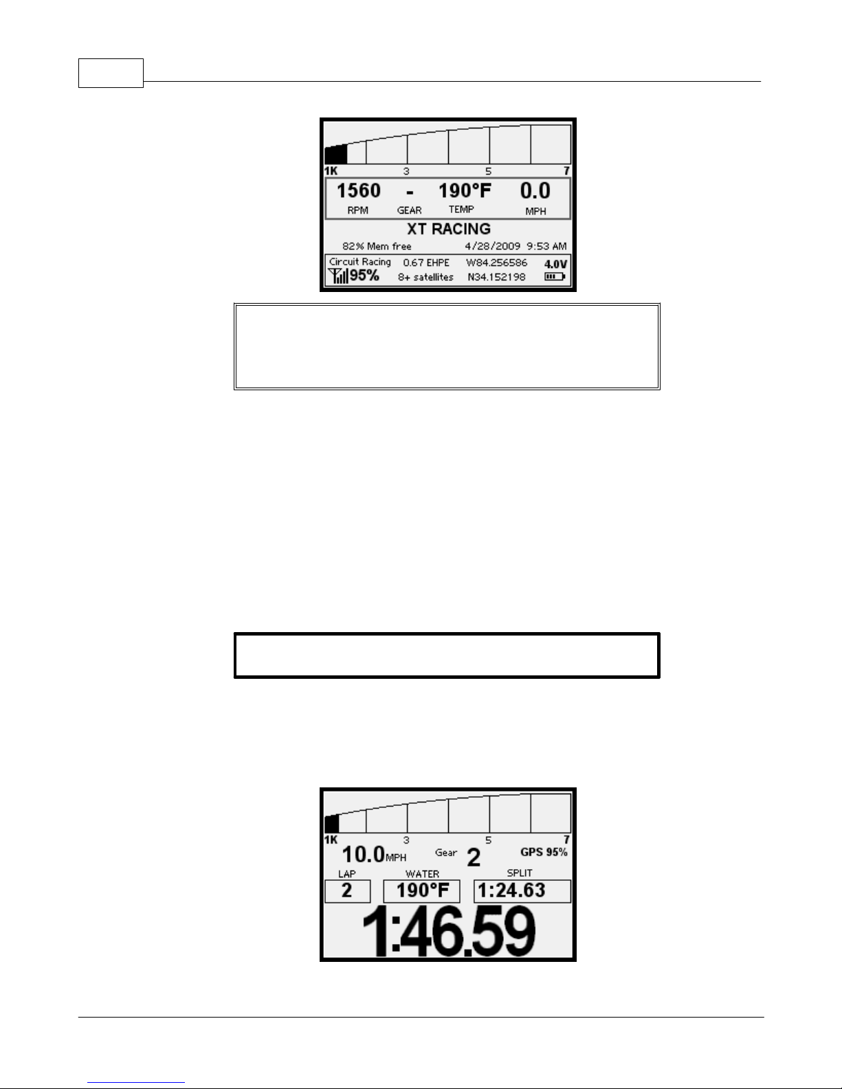
Fresh out of the box, the GPX is configured in Circuit Racing mode and is ready to go. Turn on the
GPX by pressing the Menu button and you should see the main Circuit Racing screen:
© 2009 XT Racing
Page 6
GPX Pro Manual2
NOTE: if the GPX does not power up by pressing any button, try
pressing all four buttons simultaneously. If this does not power
up the GPX, then the internal rechargeable battery is probably
discharged and will need to be charged.
The GPX needs to acquire a good signal from at least 4 GPS satellites, and an EHPE (estimated
horizontal position error) of less than 5.00. You can see the status of the GPS signals in the lower
left corner of the main screen. You might find that you get better reception by moving the
mounting position of the GPX in your vehicle. The internal antenna is positioned above the 4-way
switch. Please note that you can purchase an optional external antenna that will allow placing
the antenna separate from the GPX and often can provide better reception.
If the GPX has been powered off for less than 2 hours, then when you power up the GPX, good
signal acquisition should occur within a few seconds (depending on "view of the sky"). If the GPX
has been powered off for more than 2 hours, signal acquisition can take as long as several
minutes.
NOTE: the GPX must be on the main screen (above) when
you start a Circuit race.
Once you have acquired a good signal, you can start racing. Out of the box, the GPX will not start
operating until you reach a speed of 50 miles per hour (this is adjustable via the menu system).
This will prevent capturing lots of “garbage” data while driving/riding through the pits. Once you
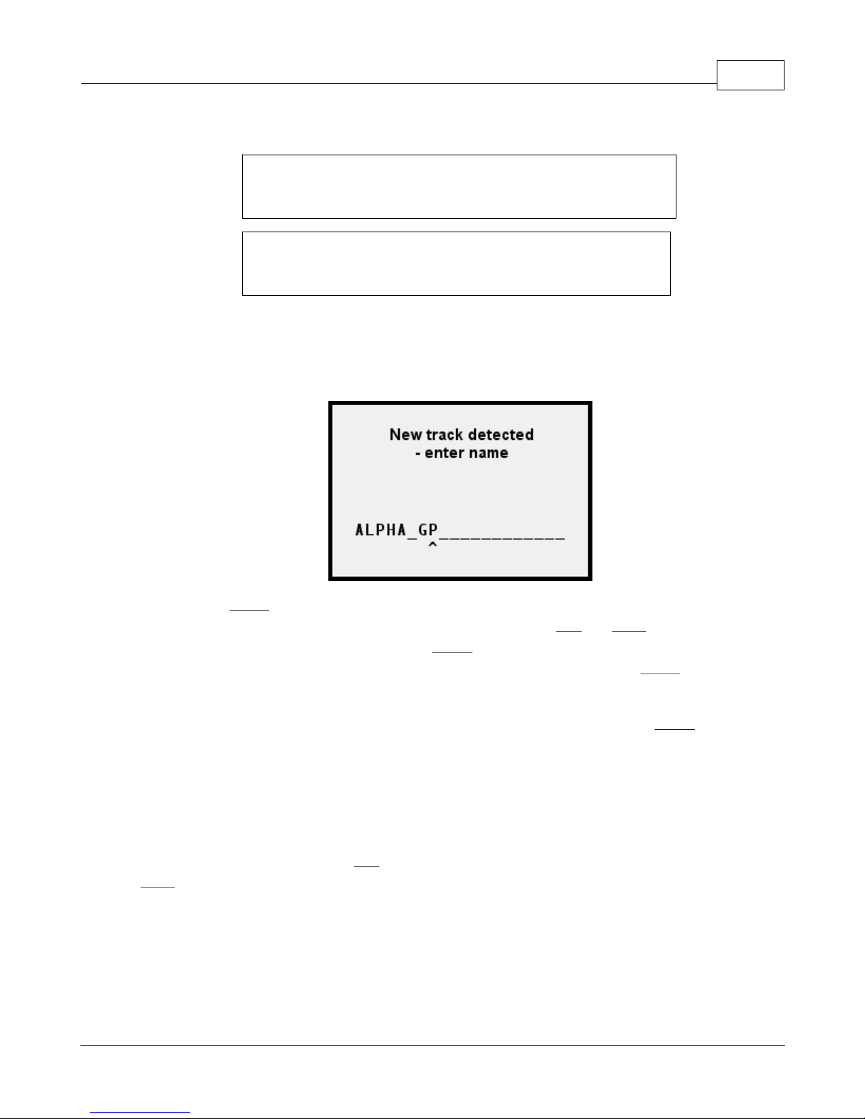
hit your starting speed, you will notice that the GPX switches to the “spinner” screen:
© 2009 XT Racing
Page 7
GPX Pro 3
This screen will be the screen shown during the entire race.
If this is the first time you have raced at this track, the device will
automatically determine that you have completed a circuit and
will start timing once it has determined the geometry of the track.
If you have raced at this track before, as soon as you cross the
start/finish line, the GPX will recognize the track and start timing
laps immediately.
Lap times will be “held” at the end of each screen for 10 seconds (menu adjustable).
When you slow down to under 5 mph (menu adjustable), the GPX will stop acquiring data for that
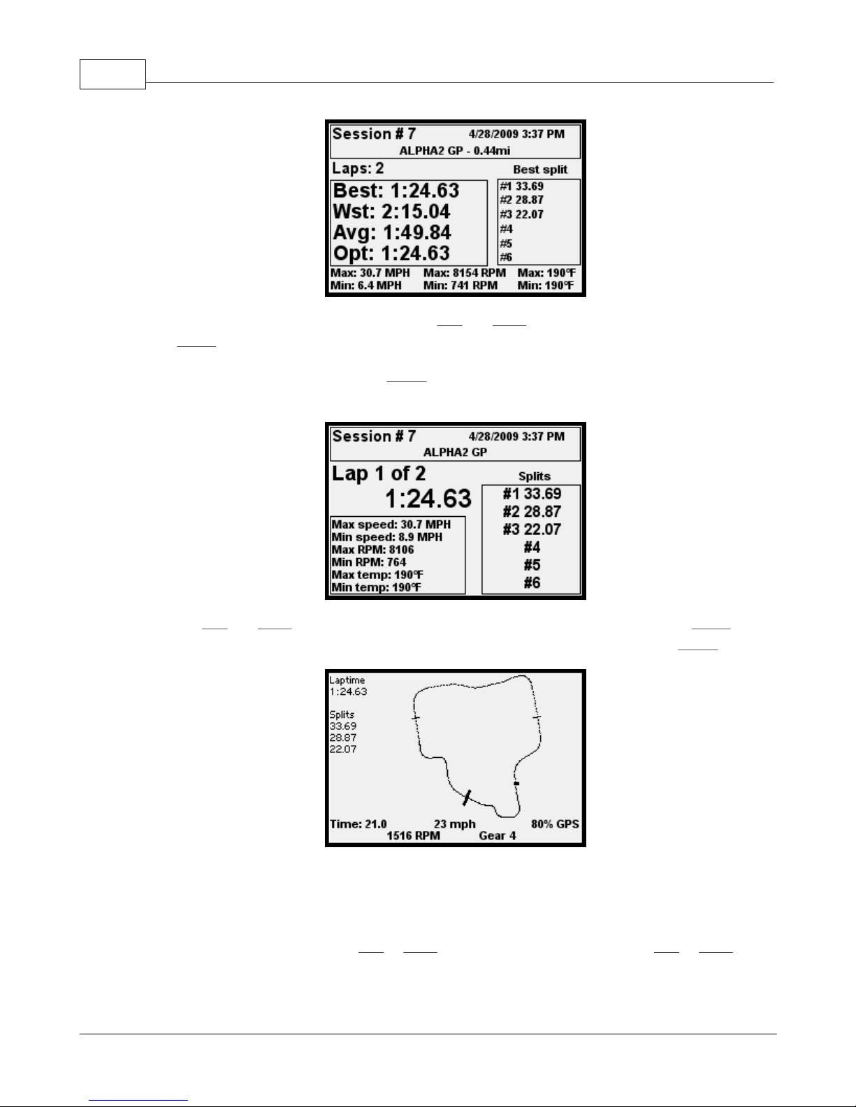
session and will ask you to name the new track you have just raced:
If you just hit Menu at this point, it will use the name suggested (NEW TRACK 1) as the track
name. If you would like to name the track otherwise, press the Left and Right arrow buttons to
cycle through letters/numbers/space. Press Select to go to the next character position, and use
the arrow buttons again. When you are done entering the track name, press Menu and you will
go back to the main screen.
NOTE: you can “back up” to the previous character position by pressing Select when a “left
arrow” shows as you’re cycling through the letters and numbers
Race again, and the whole process will start over.
Reviewing laps in Circuit Racing Mode
From the main screen, press the Left arrow to go to the first session stored in the GPX, or the
Right arrow to go to the most recently captured session. This will show a summary screen for that
session:
© 2009 XT Racing
Page 8
GPX Pro Manual4
You move from session to session by pressing Left and Right as desired. You can at this point also
press Menu to return to the main screen.
To review the laps for a session, press Select from that summary screen and you will see the lap
detail:
Press the Left and Right arrow button to cycle through the laps for that session. Press Menu to
return to the summary screen for that session. To see the track map for a lap, press Select:
On the track map screen, the dot will start moving around the track. On the bottom of the screen,
you will see the speed, time, and GPS signal strength; RPM and gear will also be shown if
captured via data acquisition.
To stop the moving dot, press the Left or Right arrow button. Then pressing the Left or Right
button will move the dot a little bit around the track.
© 2009 XT Racing
Page 9

To return to the lap detail, press Menu.
1.1.2 More Details
Lap Counter operation
The lap counter, if used, can count either up or down. Initially, before any laps have started, it
displays “-”. If set for counting up, then at the beginning of the first lap it will display “1”, and “1”
will continue to be displayed during the hold time. It will keep counting up, no matter what the
setting for “number of laps”.
If set for counting down (say the number of laps is 5), then it will display "5" during the first lap
and its hold time, and will decrease by one each lap. When that number of laps is complete, the
lap display will revert to “-“.
Tracks
The GPX automatically determines if you race at a new track that it has not yet encountered, or if
you are at a track that you have been to before. It does this by monitoring the size and shape of
the track’s “loop” and either matching it to a track that is stored in its memory, or else creating a
new track.
GPX Pro 5
Example: You go to a new track for the first time, and start racing. Once you have completed a
“loop”, the GPX determines that you are at a new track. It records your session, and when it is
done, it will default the track name to something like “NEW TRACK 1”, and you may then change
the name to the track’s actual name.
Start/Finish Line
Each track layout in the GPX has a start/finish line associated with it. (In actuality, it is a start/
finish “point”). The start-finish line is that point on the track at which a line across the track goes
through that point.
The simplest way to get a start/finish line at a new track is to do nothing. Race around the track,
and the GPX will find the “loop” point and use it for the start/finish line.
There are two modes for having the GPX determine the start/finish line (menu item Track
detection method). First loop (the default) is just that – the GPX determines the first time a loop
is “closed” and makes that point the start/finish line. Longest straight requires an additional 1-2
loops around the track, and in this case the GPX sets the start/finish line about one-third of the
way down the “longest straightaway”. (The straightaway that the GPX calculates allows for some
slight variation from a straight line]
The other way to set a start/finish at a new track is to walk over to near where you want the start/
© 2009 XT Racing
Page 10

GPX Pro Manual6
finish line to be, and set the start/finish line via the GPX’s menu system (Track options, Set start/
finish line of a new track). This point will now form the basis for the start/finish line when you
start racing the track. Please note that you should be no more than about 50 feet of where your
vehicle will cross the start/finish line in order for the GPX to recognize it while you are racing.
At any time, you may move the start/finish line for a track via the menu system. Please note that
when you move the start/finish line, it will apply to all sessions/laps stored in the GPX, and
therefore the lap and split times will be recalculated for each session at that track. When you see
the message “Recreating summary information – please wait”, this is due to the recalculation
necessary when moving start/finish line or splits.
Adding Splits, or Changing the Start/Finish Line
For an existing track, you can either move the start/finish line, add split points, or remove split
points.
In the menu system, go to Track options, then Change start-finish or maintain splits. You will now
be allowed to select from the available tracks. Pick a track using the Left and Right arrows, then
Select. Then choose whether to move the start/finish, add a split, or remove all splits. If you
move the start/finish or add a split, you will see an animated dot moving around the track. To
stop it near where you want, press either arrow to stop it. Then you may press Left or Right to
fine-tune the position. When you are happy with the position, press Select. You may press Menu
to abort the operation.
Whenever you modify the start/finish line or splits, the lap times and all summary information for
each session at that track will need to be recalculated. That calculation will occur when you view
a session at that track. You will a message stating
Recreating summary information -- please wait, and do not power
down...
This indicates that the recalculation is taking place. It generally only takes a few seconds.
Track Variation -- Clockwise vs. Counter-Clockwise
First, assume that you are letting the GPX initially determine the start/finish automatically. Also
assume the first time you race this track, you do it “clockwise”. The GPX will determine the start/
finish, and at the end of the session, you will rename the track from “NEW TRACK 1” to “MYTRACK
CW”. Now, the next time you go to the track, you start racing, but you race in the other direction.
GPX will determine that you pass by the same start/finish line, but it detects that you are going in
the opposite direction – so at the end of that session, it will prompt you for a new track like “NEW
TRACK 2” and you can then change it to “MYTRACK CCW”. As far as GPX is concerned, these are
two different tracks. Each time you race from now on, it will determine which direction you are
racing, and pick the correct track accordingly.
© 2009 XT Racing
Page 11

If you create the start/finish point manually via the menu system before racing for the first time,
it works identically – the first time you race, after the session is over, name the track
appropriately (e.g., “CW” or “CCW”). Then, just like above, when you next race in the opposite
direction, you will be prompted at the end of that session for a new name, and there will be two
track layouts.
1.1.3 Menus
Set starting speed – the speed at which the GPX starts capturing data for circuit racing
Set stopping speed – when you go below this speed, the data capture for this session is stopped
Spinner options
GPX Pro 7
Count laps
Count up – the lap counter starts at one and increases
Count down – the lap counter start at the specified count (see below) and counts
down
Set number of laps per session – used for “Count down”
Hold time at end of each lap – number of seconds your lap time will “freeze” on the
display at the end of each lap
Split hold time – number of seconds each split time will “freeze” on the display when you
pass the split
Track options
Track detection method
Set the start/finish line of a new track – allows you to manually “create a new track” by
physically going to the start/finish line to register the GPS coordinate
Change start/finish
First loop – a new track will be detected as soon as a complete loop is detected
and the start/finish line will be set at that point
Longest straight – a new track will be detected as soon as a complete loop is
detected, but the start/finish line will be set 1-2 laps later, about 1/3 of the way
down the longest straightaway
(select a track) - allows you to move the start/finish line
© 2009 XT Racing
Page 12

GPX Pro Manual8
Maintain splits
(select a track)
Add split – adds a new split for this track. There is a limit of 5 splits.
Remove a split – removes the selected split (a little box indicates which
split will be removed when you press Select)
Remove all splits – deletes all the splits
Rename a track – change the name of an existing track
Data acquisition setup and parameters
For detailed information, see the section Data Acquisition (DAQ)
Tachometer options – controls how the tach lights and tach bar during races will be utilized
Tach style – how the 8 LEDS will be utilized
Off – lights will not be used for anything
1 LED at a time – only one LED lights up at a time
All LEDs – more LEDs light up at increasing RPMs (consumes more battery power!)
Thumbs up/down – lights are not used for RPM. In Circuit racing, if you do a faster
lap than the previous, the green lights will blink; if a slower lap, the red lights will
blink.
Tach brightness – a setting from 1-10 of increasing brightness of the tach lights
Tach RPM Green – the RPM that the green LEDs come on
Tach RPM Yellow – the RPM at which the yellow LEDs start coming on
Tach RPM Red – The RPM at which the red LEDS start coming on
Tach RPM white (shift light) – the “redline”
Shift light style - what happens when you exceed the "redline"
White LEDs blink
White LEDs solid
All LEDs blink
© 2009 XT Racing
Page 13

Tach Display Minimum RPM – this is the minimum RPM on the Tach that displays on the
LCD graph
Tach Display Maximum RPM – this is the maximum RPM on the Tach that displays on the
LCD graph
LCD Display Options
Backlight on/off control – control over the LCD panel backlight
Off – no backlight
On Activity – turns on for about 10 seconds after every keypress, and lap or split
completed
Always ON – always on (consumes more battery power!)
Backlight brightness – a value from 1-10 controlling the brightness (higher values use
more battery power!)
GPX Pro 9
LCD contrast – adjusts the contrast of the LCD panel
Normal or reverse display
Normal display – Black characters on a white background
Reverse display – White characters on a black background
Power-Off Options
Power off now -- selecting this immediately turns off the GPX
Minutes until auto power off – after this many minutes of no activity, the GPX will turn off
File Maintenance
Delete last viewed session (for deleting the last session you viewed in the GPX)
(confirmation required)
Delete a track and its sessions - see section on File Maintenance
(confirmation required)
Delete all sessions for a track -- see section on File Maintenance
(confirmation required)
Delete all session -- see section on File Maintenance
© 2009 XT Racing
Page 14

GPX Pro Manual10
(confirmation required)
Delete all tracks and sessions -- see section on File Maintenance
(confirmation required)
File system check – checks the integrity of the GPX’s built-in file system
Display Formats and Units
Time Format – specifies how times will be displayed
16:26 style
4:26 PM style
Date format – specifies how dates will be displayed
4/23/2008 – month/day/year
2008/04/23 – year/month day
RPM format – specifies how RPMs will be displayed
11200 – full value
11.2K – in K
Miles per hour or kilometers per hour
MPH – distances and speeds based on miles
KPH – distances and speeds based on kilometers
Fahrenheit or Celsius -- specify the temperature scale
Fahrenheit
Celsius
Latitude/longitude format - display and data entry method for coordinates
N34 13.7326 -- degrees, minutes, fractional minutes
N34.228877 -- degrees, fractional degrees
Miscellaneous
Odometer/hour meters
© 2009 XT Racing
Page 15

GPX Pro 11
Show distance/time meters -- displays their current values
Clear distance/time meter 1
Clear distance/time meter 2
Set local time – sets the local time as a variation from UTC (Greenwhich Mean Time)
Personalization -- owner information
Set personalization line 1
Set personalization line 2
Clear personalization line 1
Clear personalization line 2
Show Version Information – displays information about the GPX software version
Reset settings to factory default – resets all settings. Does not delete sessions or tracks.
(confirmation required)
Device mode – changes the basic racing mode of the GPX
Circuit Racing – races that occur repetitively over the same course (circle, oval, road
racing)
Point-to-Point Racing – racing from a start point to a finish point (rally)
Drag racing – 0-60, 0-60-0, ¼ mile, etc.
Instrument Cluster – a "dashboard"
1.2 Point-to-Point Racing Mode
Point-to-Point Racing mode is for races that start at a starting point and end at a finishing point –
rally races, for example. Up to 5 split points may be defined.
1.2.1 Basic Operation
Unlike Circuit Mode, in Point-to-Point mode, the GPX cannot determine the start and finish for
the race. You must “create” a new track, then define the start and finish point. (And optionally
define split points.)
To “create” the new track, go into the menu system, go to Track Options, then press Select. Using
© 2009 XT Racing
Page 16
GPX Pro Manual12
the arrows, go to Create a new track, and press Select. Enter the name of the new track using
arrows and Select. Press Menu when the name is complete.
Now, physically go to the starting point of the race. On the main screen, make sure you have a
good GPS signal (4 or more satellites, less than 5.00 EHPE). Go into the menu system, go to Track
Options, and using the arrows go to Set start point. Press Select. You will now choose the track
using the arrows (if you only have one point-to-point track in the GPX, it will be shown with no
left or right arrow showing). Press Select on that track. Make sure you are at the starting point,
and press Select. After a few seconds, the GPS information will be recorded, and it will return to
the menu system.
Do the same procedure for the finish of the race by going to Set finish point and following the
same steps.
Do the same if you want to enter any split points for the race. Please note that you do not have to
set the start point before you set the finish point – you may define the start/finish/split points in
any convenient order.
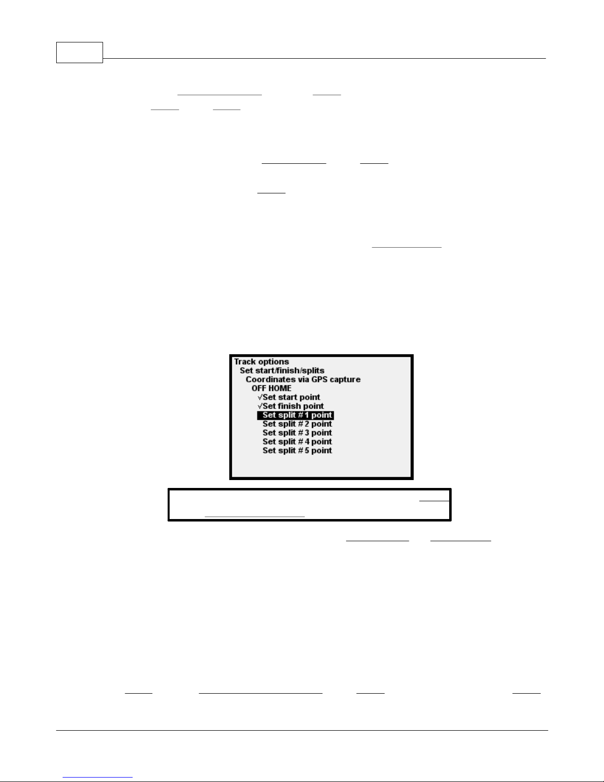
Notice that on the menus, a check mark is displayed next to each point which you have defined:
To start the race, go into the menu system, go to Select
There are two methods to start a point-to-point race --Standing start and Running start. Use
standing start when a race starter starts you. (For standing start, the "start point" of the race is not
actually used -- it assumes you are starting from the correct spot.) For a standing start, the
accelerometers must "zero" themselves, which takes a few seconds when you select the track to
start the race. Zeroing of the accelerometers allows the GPX to determine the precise instant
when you start your motion and starts timing from that point in time.
If you choose "running start", then you must approach the start point going at least 5 mph. When
you pass the start point, the timing of the race starts, and the "spinner screen" displays.
To start a point-to-point race, first position yourself to start the race. Then, from the main screen
press Menu and go to Select a track to start a race. Press Select. Pick the track name, press Select
a track to start race, and select the track.
© 2009 XT Racing
Page 17
GPX Pro 13
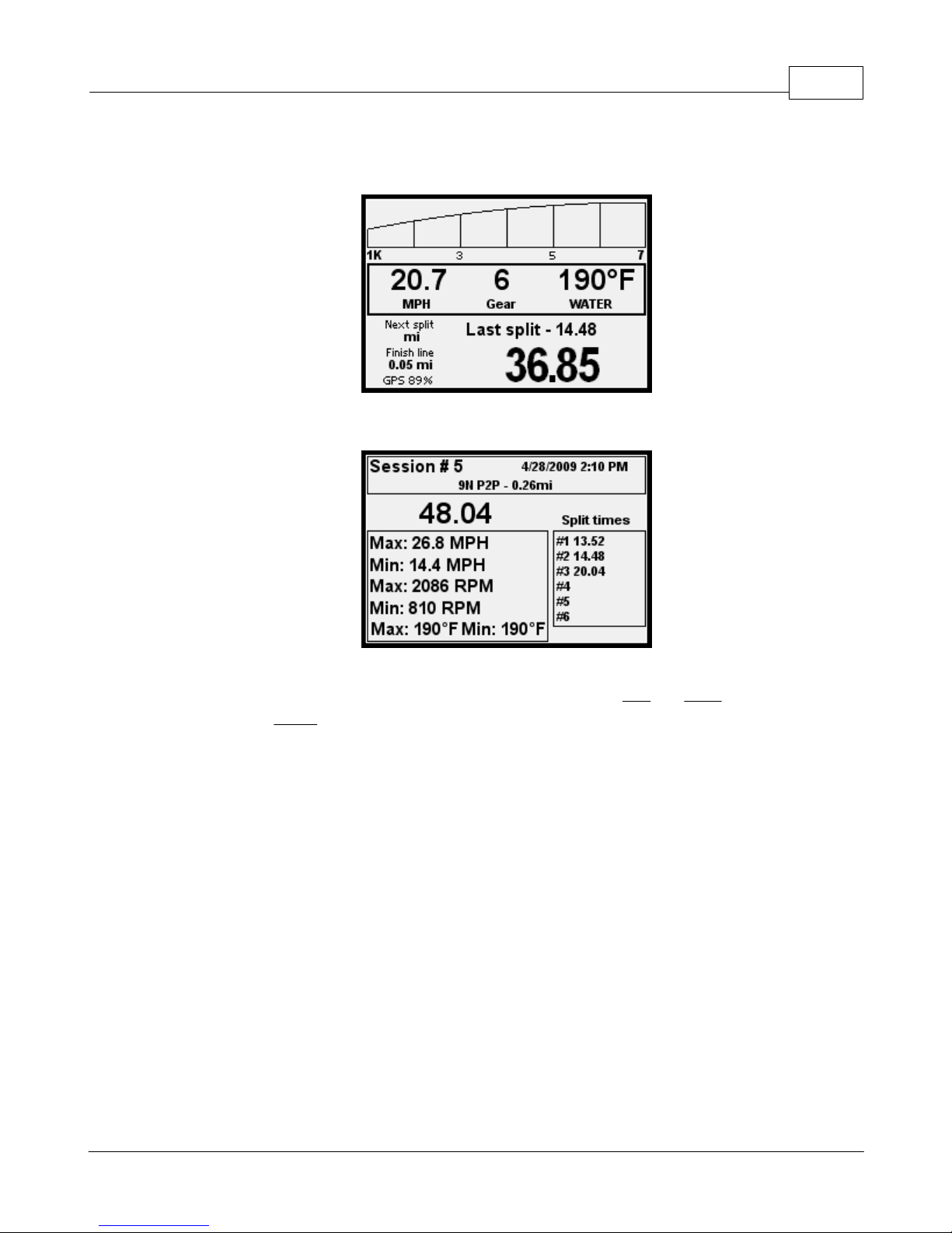
to select that track, and start racing. As soon as you pass the start point, the GPX will begin timing
and acquiring data:
When the race is over, the summary screen for that race will automatically be shown:
To review your point-to-point races, from the main screen, press Left and Right to cycle through
the races. Press Menu to return to the main screen.
1.2.2 More Details
Direct entry of start/finish/split coordinates
There is another method of entering the points for a point-to-point track -- direct entry of GPS
coordinates. To do this, you must obtain the latitude and longitude of the points. For example,
the website http://itouchmap.com/latlong.html is one such source.
There are two common formats for latitude/longitude -- degree/minute/fractional minute, and
degree/fractional degree. You can, through the menu selection "Display formats and units",
select which one you will use. (For example, the above website reports coordinates in the
degree/fractional degree format.)
For latitude, positive numbers are NORTH and negative numbers are SOUTH. For longitude,
positive numbers are EAST and negative numbers are WEST. When entering coordinates
manually, the GPS requires N/S and E/W.
© 2009 XT Racing
Page 18
GPX Pro Manual14
If a coordinate contains more decimal points than the GPX can handle, you can safely ignore the
extra digits.
Use the Left and Right arrows to change each position of data entry, and press Select to go to the
next position. Press Menu when complete.
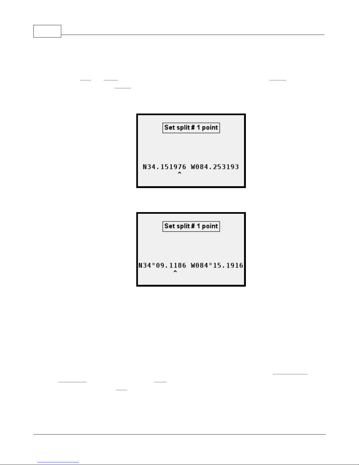
Example of coordinate entry using degree/fractional degree:
Example of coordinate entry using degree/minute/fractional minute:
Distance to next split and finish
The default spinner screen for point-to-point shows the distance to the next split, and the
distance to the finish. These are straight-line distances "as the crow flies".
Accelerometer sensitivity
Depending on the mounting of the GPX and the amount of vehicle vibration, you may need to
adjust the acceleration sensitivity when doing a standing start. The menu item Acceleration
sensitivity allows you to change it. High sensitivity means the GPX will be most sensitive to the
slightest movement; Low means the GPX will be more lenient to vibration.
© 2009 XT Racing
Page 19
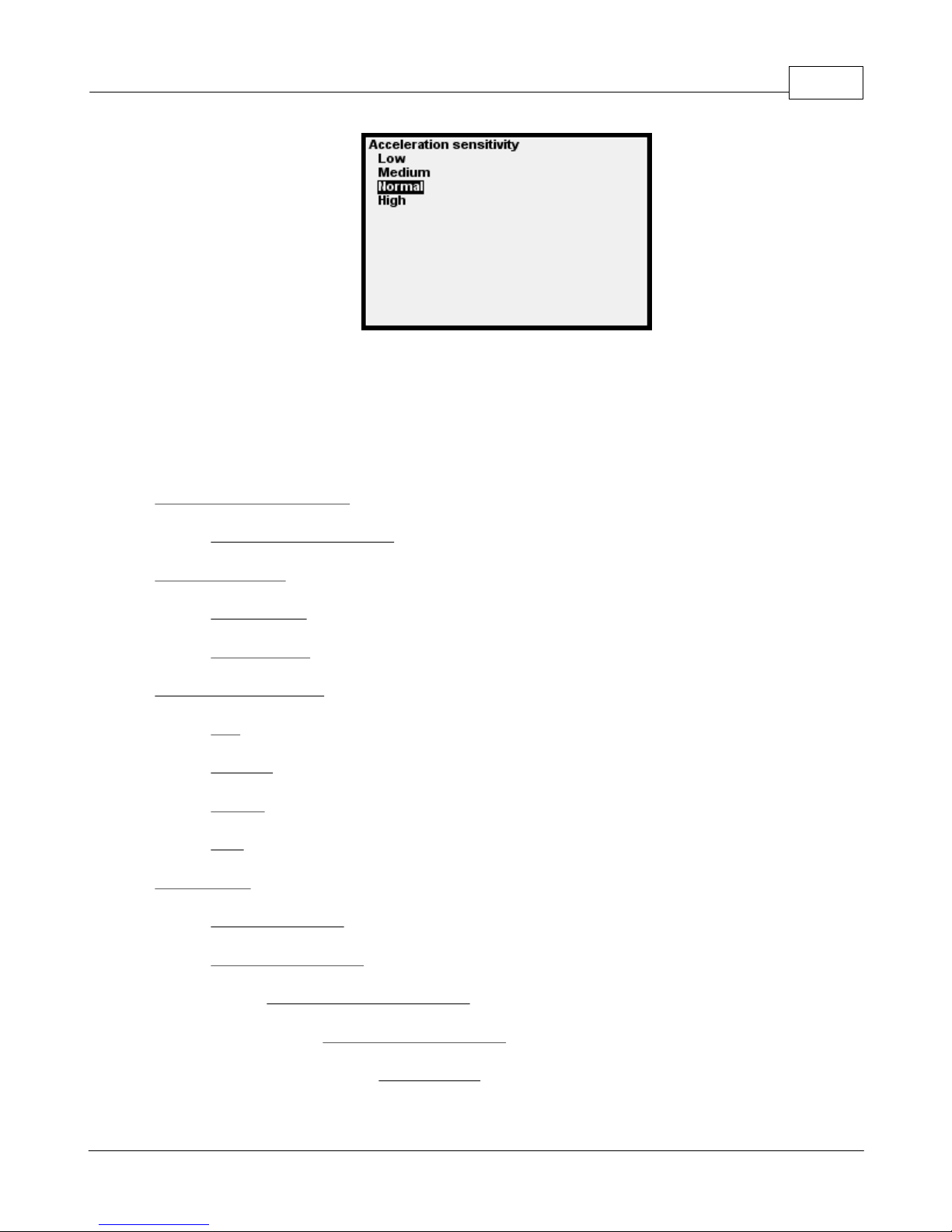
If you find that the GPX starts timing a standing start before you start your vehicle, change the
sensitivity to a lower setting.
1.2.3 Menus
Select a track to start a race
GPX Pro 15
(select from list of tracks) - when you select the track, the race is ready to start
Race start method
Running start - you start behind the starting line and "fly by" the start line
Standing start - a race "starter" starts you. Timing starts when the vehicle goes in motion
Acceleration sensitivity - adjust how sensitive standing-start detection is
Low
Medium
Normal
High
Track options
Create a new track - enter the name of a new track
Set start/finish/splits
Coordinates via GPS capture - go to the spot and record GPS coordinates
© 2009 XT Racing
(select from list of tracks)
Set start point
Page 20

GPX Pro Manual16
Set finish point
Set split # 1 point
...
Set split # 5 point
Coordinates via keypad entry - enter known latitude and longitude
(select from list of tracks)
Set start point
Set finish point
Set split # 1 point
...
Set split # 5 point
Rename a track
(select from list of tracks)
Data acquisition setup and parameters
For detailed information, see the section Data Acquisition (DAQ)
Tachometer options – controls how the tach lights and tach bar during races will be utilized
Tach style – how the 8 LEDS will be utilized
Off – lights will not be used for anything
1 LED at a time – only one LED lights up at a time
All LEDs – more LEDs light up at increasing RPMs (consumes more battery power!)
Thumbs up/down – lights will not come on in point-to-point mode
Tach brightness – a setting from 1-10 of increasing brightness of the tach lights
Tach RPM Green – the RPM that the green LEDs come on
Tach Yellow – the RPM at which the yellow LEDs start coming on
Tach Red – The RPM at which the red LEDS start coming on
© 2009 XT Racing
Page 21

Tach RPM white (shift light) – the “redline”
Shift light style - what happens when you exceed the "redline"
White LEDs blink
White LEDs solid
All LEDs blink
Tach Display Minimum RPM – this is the minimum RPM on the Tach that displays on the
LCD graph
Tach Display Maximum RPM – this is the maximum RPM on the Tach that displays on the
LCD graph
LCD Display Options
Backlight on/off control – control over the LCD panel backlight
GPX Pro 17
Off – no backlight
On Activity – turns on for about 10 seconds after every keypress, and lap or split
completed
Always ON – always on (consumes more battery power!)
Backlight brightness – a value from 1-10 controlling the brightness (higher values use
more battery power!)
LCD contrast – adjusts the contrast of the LCD panel
Normal or reverse display
Normal display – Black characters on a white background
Reverse display – White characters on a black background
Power-Off Options
Power off now -- selecting this immediately turns off the GPX
Minutes until auto power off – after this many minutes of no activity, the GPX will turn off
File Maintenance
Delete last viewed session (for deleting the last session you viewed in the GPX)
(confirmation required)
© 2009 XT Racing
Page 22

GPX Pro Manual18
Delete a track and its sessions - see section on File Maintenance
(confirmation required)
Delete all sessions for a track -- see section on File Maintenance
(confirmation required)
Delete all session -- see section on File Maintenance
(confirmation required)
Delete all tracks and sessions -- see section on File Maintenance
(confirmation required)
File system check – checks the integrity of the GPX’s built-in file system
Display Formats and Units
Time Format – specifies how times will be displayed
16:26 style
4:26 PM style
Date format – specifies how dates will be displayed
4/23/2008 – month/day/year
2008/04/23 – year/month dayt
RPM format – specifies how RPMs will be displayed
11200 – full value
11.2K – in K
Miles per hour or kilometers per hour
MPH – distances and speeds based on miles
KPH – distances and speeds based on kilometers
Fahrenheit or Celsius -- specify the temperature scale
Fahrenheit
Celsius
© 2009 XT Racing
Page 23

Latitude/longitude format - display and data entry method for coordinates
Miscellaneous
Odometer/hour meters
Set local time – sets the local time as a variation from UTC (Greenwhich Mean Time)
Personalization -- owner information
GPX Pro 19
N34 13.7326 -- degrees, minutes, fractional minutes
N34.228877 -- degrees, fractional degrees
Show distance/time meters -- displays their current values
Clear distance/time meter 1
Clear distance/time meter 2
Set personalization line 1
Set personalization line 2
Clear personalization line 1
Clear personalization line 2
Show Version Information – displays information about the GPX software version
Reset settings to factory default – resets all settings. Does not delete sessions or tracks.
(confirmation required)
Device mode – changes the basic racing mode of the GPX
Circuit Racing – races that occur repetitively over the same course (circle, oval, road
racing)
Point-to-Point Racing – racing from a start point to a finish point (rally)
Drag racing – 0-60, 0-60-0, ¼ mile, etc.
Instrument Cluster – a "dashboard"
1.3 Drag Racing Mode
Drag Racing mode allows you to perform a “drag session” and record data for that session. A
number of different types of drag modes are supported – ¼ mile, 1/8 mile, 1 mile; 0-30, 0-60, 0-
© 2009 XT Racing
Page 24
GPX Pro Manual20
100 mph; 0-30-0, 0-60-0, 0-100-0 mph; and a roll-on mode which times and measures from a
programmable start speed to a programmable stop speed (for example, 60-100 mph).
1.3.1 Basic Operation
In Drag Racing mode, you can select from the following types of drag race via the menu item Type
of drag race:
1/8 mile; ¼ mile; 1 mile
0-30 mph; 0-60 mph; 0-100 mph
0-30-0 mph; 0-60-0 mph; 0-100-0 mph
“Roll-on” (e.g., 60-100 mph)
In addition, for each race type (except roll-on), you can select how you will start the session via
the menu item Drag race starting method: “Standing Start" (timing starts whenever the vehicle
starts moving), or “Tree lights” (you start after a brief cycling of red to yellow to green) and the
reaction time is recorded. There is no “track” for drag racing. You can do it anywhere.
To start a drag race (after you have selected the type
of race and starting method), press Select from the
main menu.
For a few seconds, the GPX will “zero out” the internal accelerometers. Then either you can start
when you’re ready ("Standing start"), or start when the tree lights go green.
NOTE: The internal accelerometers are extremely sensitive.
Especially for drag racing, you must mount the GPX in such a
way as to minimize vibration.
During the 0-30-0, 0-60-0, and 0-100-0 races, the display of the GPX will invert (i.e., reverse black
and white) when you hit the top speed (30, 60, or 100 appropriately). This is the indication that
you have hit the maximum speed and need to start the deceleration (braking) portion of the drag.
© 2009 XT Racing
Page 25
GPX Pro 21
Similarly, during a roll-on, the display of the GPX will invert when you hit the minimum speed (e.
g., 60 if the setting is for a 60-100 roll-on), and will revert back to normal when you hit the top
speed.
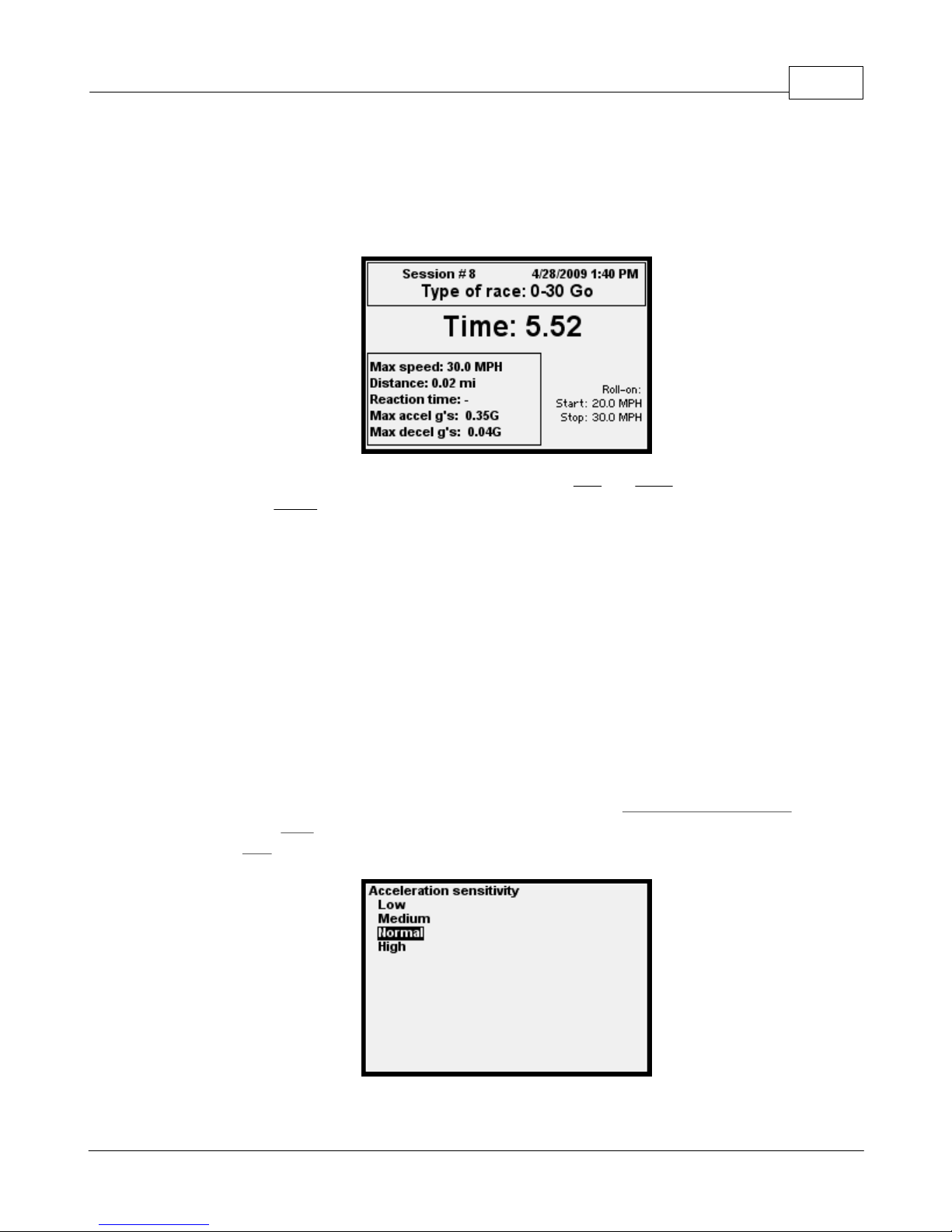
When the drag is completed, its summary screen is shown:
To review your drag races, from the main screen press the Left and Right arrows to cycle through
the races. Press Menu to return to the main screen.
When you start a drag session, if you change your mind, press any button to terminate it.
When you do a roll-on, if the roll-on maximum speed is less than the roll-on minimum speed + 10,
the maximum speed is set to the minimum speed + 10. For example, if you set the roll-on
minimum speed to 50, and the roll-on maximum speed to 55, the maximum will actually be set to
60. (There must be at least a 10 mph difference from the minimum to the maximum.)
1.3.2 More Details
Accelerometer sensitivity
Depending on the mounting of the GPX and the amount of vehicle vibration, you may need to
adjust the acceleration sensitivity for drag races. The menu item Acceleration sensitivity allows
you to change it. High sensitivity means the GPX will be most sensitive to the slightest
movement; Low means the GPX will be more lenient to vibration.
If you find that the GPX starts timing a drag race before you start your vehicle, change the
© 2009 XT Racing
Page 26

GPX Pro Manual22
sensitivity to a lower setting.
1.3.3 Menus
Type of drag race
1/8 mile
1/4 mile
1 mile
0-30
0-60
0-100
0-30-0
0-60-0
0-100-0
Roll-on - times race from a specified start speed (roll-on start speed) to a higher stop
speed (roll-on stop speed)
Drag race starting method
Standing start - start whenever you're ready
Tree lights -- start when the LEDs go green (measures reaction time or foul) (not
applicable for roll-on)
Roll-on start speed
Roll-on stop speed
Acceleration sensitivity - adjusts how sensitive start detection is
Low
Medium
Normal
High
© 2009 XT Racing
Page 27

GPX Pro 23
Data acquisition setup and parameters
For detailed information, see the section Data Acquisition (DAQ)
Tachometer options – controls how the tach lights and tach bar during races will be utilized
Tach style – how the 8 LEDS will be utilized
Off – lights will not be used for anything
1 LED at a time – only one LED lights up at a time
All LEDs – more LEDs light up at increasing RPMs (consumes more battery power!)
Thumbs up/down – lights are not used for RPM. In Circuit racing, if you do a faster
lap than the previous, the green lights will blink; if a slower lap, the red lights will
blink.
Tach brightness – a setting from 1-10 of increasing brightness of the tach lights
Tach RPM Green – the minimum RPM that the green LEDs come on
Tach Yellow – the RPM at which the yellow LEDs start coming on
Tach Red – The RPM at which the red LEDS start coming on
Tach RPM white (shift light) – the “redline”
Shift light style - what happens when you exceed the "redline"
White LEDs blink
White LEDs solid
All LEDs blink
Tach Display Minimum RPM – this is the minimum RPM on the Tach that displays on the
LCD graph
Tach Display Maximum RPM – this is the maximum RPM on the Tach that displays on the
LCD graph
LCD Display Options
Backlight on/off control – control over the LCD panel backlight
Off – no backlight
On Activity – turns on for about 10 seconds after every keypress, and lap or split
© 2009 XT Racing
Page 28

GPX Pro Manual24
completed
Always ON – always on (consumes more battery power!)
Backlight brightness – a value from 1-10 controlling the brightness (higher values use
more battery power!)
LCD contrast – adjusts the contrast of the LCD panel
Normal or reverse display
Normal display – Black characters on a white background
Reverse display – White characters on a black background
Power-Off Options
Power off now -- selecting this immediately turns off the GPX
Minutes until auto power off – after this many minutes of no activity, the GPX will turn off
File Maintenance
Delete last viewed session (for deleting the last session you viewed in the GPX)
(confirmation required)
Delete a track and its sessions - see section on File Maintenance
(confirmation required)
Delete all sessions for a track -- see section on File Maintenance
(confirmation required)
Delete all session -- see section on File Maintenance
(confirmation required)
Delete all tracks and sessions -- see section on File Maintenance
(confirmation required)
File system check – checks the integrity of the GPX’s built-in file system
Display Formats and Units
Time Format – specifies how times will be displayed
16:26 style
© 2009 XT Racing
Page 29

4:26 PM style
Date format – specifies how dates will be displayed
4/23/2008 – month/day/year
2008/04/23 – year/month dayt
RPM format – specifies how RPMs will be displayed
11200 – full value
11.2K – in K
Miles per hour or kilometers per hour
MPH – distances and speeds based on miles
KPH – distances and speeds based on kilometers
Fahrenheit or Celsius -- specify the temperature scale
GPX Pro 25
Latitude/longitude format - display and data entry method for coordinates
Miscellaneous
Odometer/hour meters
Set local time – sets the local time as a variation from UTC (Greenwhich Mean Time)
Personalization -- owner information
Fahrenheit
Celsius
N34 13.7326 -- degrees, minutes, fractional minutes
N34.228877 -- degrees, fractional degrees
Show distance/time meters -- displays their current values
Clear distance/time meter 1
Clear distance/time meter 2
Set personalization line 1
Set personalization line 2
© 2009 XT Racing
Page 30
GPX Pro Manual26
Clear personalization line 1
Clear personalization line 2
Show Version Information – displays information about the GPX software version
Reset settings to factory default – resets all settings. Does not delete sessions or tracks.
(confirmation required)
Device mode – changes the basic racing mode of the GPX
Circuit Racing – races that occur repetitively over the same course (circle, oval, road
racing)
Point-to-Point Racing – racing from a start point to a finish point (rally)
Drag racing – 0-60, 0-60-0, ¼ mile, etc.
Instrument Cluster – a "dashboard"
1.4 Instrument Cluster Mode
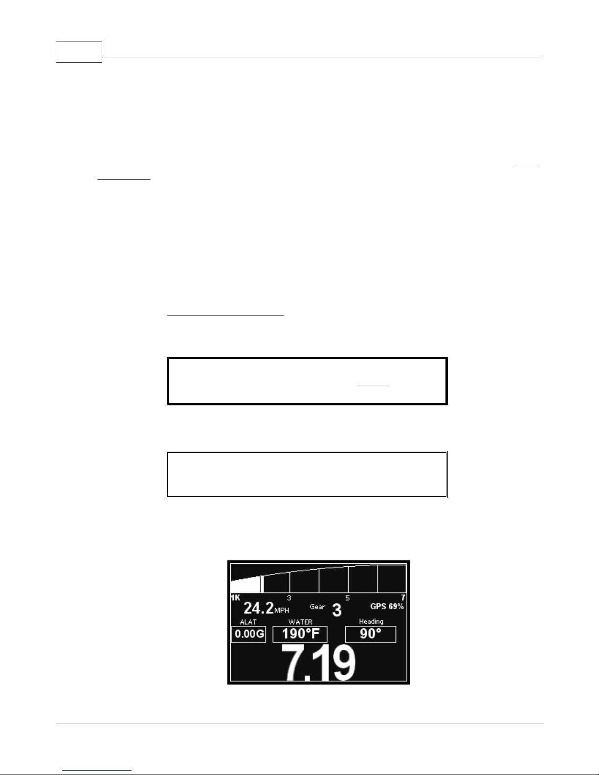
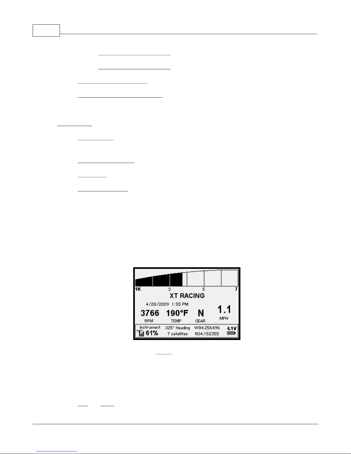
In Instrument Cluster Mode, there is only one screen -- the main screen. Use this mode as a
"dashboard" when you are not racing. You can display speed, RPM, battery status, GPS status, as
well as any of your data acquisition values.
Here is the default instrument cluster main screen:
From this main screen, you can press Menu to enter the menu system.
1.5 Menu System and Navigation
The menu system allows you to change many settings within the GPX, as well as switch the basic
racing modes. No matter what menu you’re in, the operation is pretty much the same:
Left and Right arrows cycle through current menu choices – the current choice is always
© 2009 XT Racing
Page 31
GPX Pro 27
highlighted:
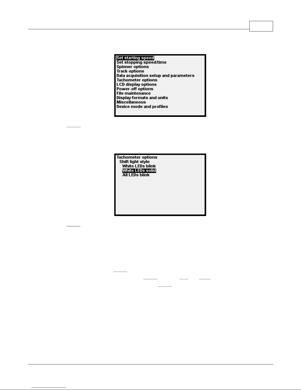
Select “selects” that option. It either records a menu setting, or goes to another menu.
When you are several levels deep in the menus, the previous selections show on the top
of the screen, and the current choices are indented the furthest:
Menu “backs up”. If you are at the top level of the menu system, it returns to the main
screen.
1.6 Switching Racing Modes
To switch racing modes (for example, you are in Circuit Racing and you want to go to Drag Racing),
from the main screen, press Menu to go into the menu system. Use the arrows to highlight the
last menu item (Device Mode), and press Select. Use the Left and Right arrows until the mode
you wish to change to is highlighted, then press Select. The GPX will restart in the selected mode.
1.7 Data Acquisition (DAQ)
1.7.1 Basic Information
Your GPX is capable of capturing other data in addition to the speed, acceleration data, and GPS
© 2009 XT Racing
Page 32

GPX Pro Manual28
coordinates which determine the lap and split times. Y can capture RPM, gear, suspension, and
other inputs from your racing vehicle.
NOTE: throughout this manual, the words input and channel refer
to one and the same thing.
Cabling and Electrical Information
There are two sets of expansion cables supplied with the GPX Pro, labeled “A” and “B”. If you use
these expansion cables, make sure that you plug the “A” cable into the “A” connector and the “B”
cable into the “B” connector.
NOTE: For each cable you connect to your vehicle, make sure that
the black wire is well fastened to the vehicle’s
“ground” (essentially the negative terminal of the battery). If
direct connection to the battery is not feasible, you may connect it
to the metal chassis as long as a good electrical connection is
made from the black wires to the chassis, and the chassis has a
good electrical connection to the vehicle’s negative battery
terminal.
12V Power
You may connect the GPX to the 12V power (essentially, the positive terminal of the vehicle’s
battery). This is done with the RED WIRE OF CABLE “A”. If you connect to the vehicle’s 12V, then
the GPX will always be powered by your vehicle. (The internal battery will be continuously
charged.) So that the GPX does not drain the vehicle’s battery when the vehicle is turned off, it is
preferable to connect the 12V power wire to the GPX via a switched power point so that when the
vehicle is turned off, the 12V is not supplied to the GPX. If this is not feasible, it is recommended
that you disconnect CABLE A when you are done racing.
Analog vs. Digital Signals
Analog signals typically have a range of from 0 to 5 volts. These signals generally can have any
value in that range. Typical examples of analog inputs would be engine coolant temperature,
suspension via linear potentiometers, or throttle position. In addition, a switch input (on/off
type of signal) (e.g., idiot oil warning light) may be connected to any of the analog inputs.
Digital signals are pulsed inputs (e.g., RPM or wheel speed sensor). The GPX can handle digital
signals which have swings in the 0-5V range to signals with swings in the 0-12V range.
GPX DAQ Inputs
© 2009 XT Racing
Page 33

GPX Pro 29
Analog/digital input # 1 is the BROWN WIRE OF CABLE “A”. It may be used as either an analog or
digital input.
Analog input # 2 is the YELLOW WIRE OF CABLE “A”. Analog only.
Analog input # 3 is the BLUE WIRE OF CABLE “B”. Analog only.
Analog input # 4 is the GREEN WIRE OF CABLE “B”. Analog only.
Digital input # 5 is the GREEN WIRE OF CALBE "A". Digital only.
© 2009 XT Racing
Page 34
GPX Pro Manual30
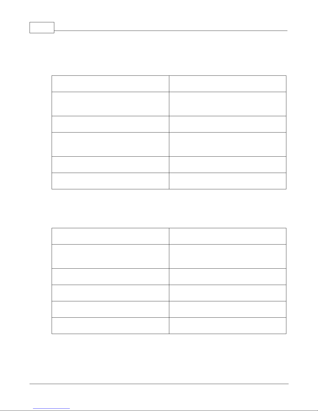
Black wire
Connect to vehicle’s negative battery terminal
Red wire
Connect to (preferably switched) source of 12V
(positive battery terminal)
Green wire
Digital input # 5
Blue wire
Connect to coiled wire around spark plug if
utilizing coupled (inductive) RPM pickup
Brown wire
Analog/digital input # 1
Yellow wire
Analog input # 2
Black wire
Connect to vehicle’s negative battery terminal
Red wire
3V output. May be used to power linear
potentiometers for suspension inputs.
Green wire
Analog input # 4
Blue wire
Analog input # 3
Brown wire
Do not use. Future expansion.
Yellow wire
Do not use. Future expansion.
Wiring Summary – CABLE “A”
Wiring Summary – CABLE “B”
© 2009 XT Racing
Page 35
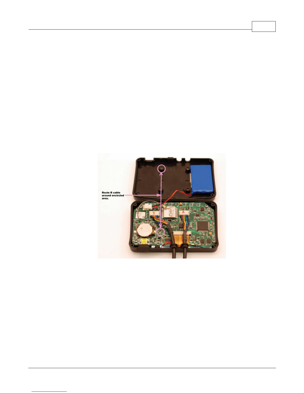
1.7.1.1 Installing Cables
Two cables are supplied with the GPX Pro. Cable A and Cable B each have 6 wires.
1. Remove the 4 screws holding the back cover on the GPX Pro.
2. Flip the cover up as in the picture below. Be extremely careful when removing the back cover
as the Li-Ion battery is attached to the back cover.
3. Plug in the A cable for onboard vehicle battery power and DAQ inputs 1, 2, and 5 (digital RPM).
If you are using data channels 3 or 4, you will also need the B cable.
4. Route the cables as shown in the picture below. Cable B specifically has to route to miss the
mounting post circled.
5. Looking from the back -- cable A goes in the far right grommet hole, and cable B in the middle
one. The third grommet holes is used for the optional external antenna.
6. Make sure the grommets are oriented correctly, and near their final location
7. Flip the back cover over and fit the grommets to their holes.
8. Install the screws, being careful not to over-tighten them.e
GPX Pro 31
1.7.1.2 Wiring with Scotchlok Connectors
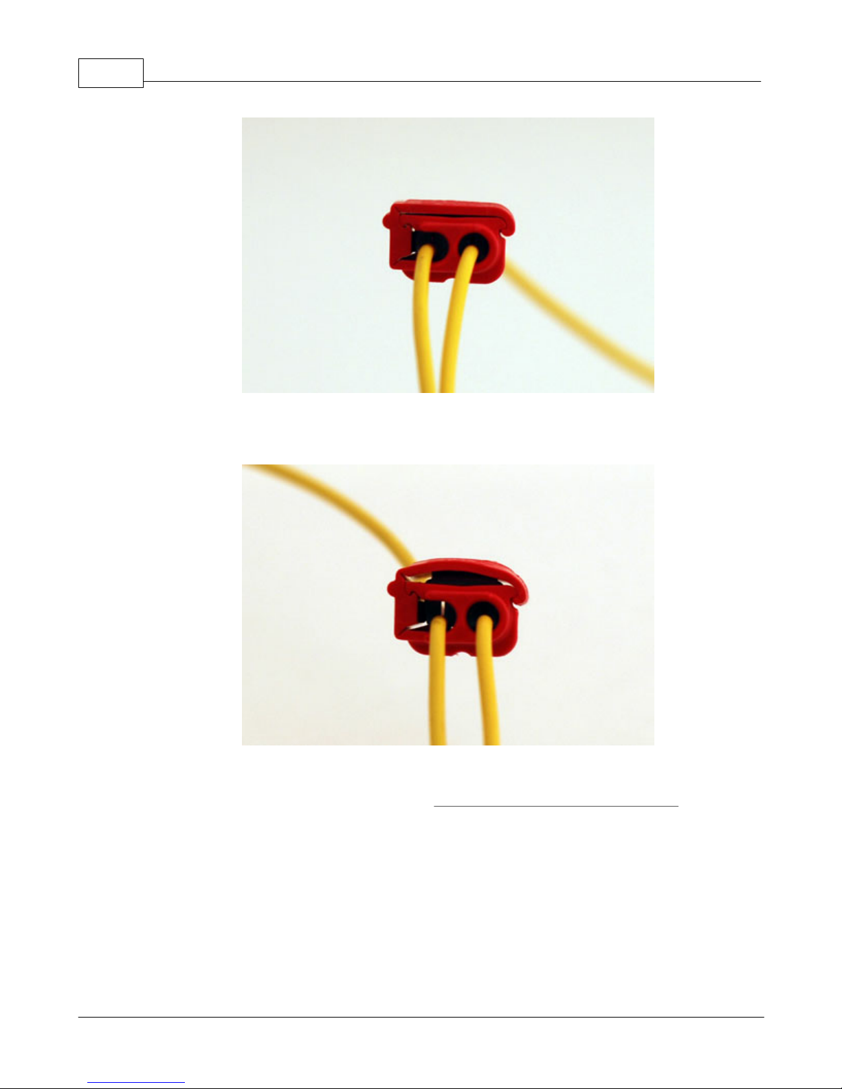
Included with your GPX Pro is a set of Scotchlok connectors that can be pressed onto your wires
with no stripping or soldering required. Supplied initially are 6 of these connectors in order to
begin wiring your vehicle to collect data. More Scotchloks and color-coded wiring can be
purchased in our DAQ Wire Kits at www.xtracing.com. All wire used with Scotchlok connectors
must be 22-16 AWG. We have found that most vehicles use wiring within this range. Make sure
that the metal tab in each Scotchlok is pressed down firmly over both wires before you close the
Scotchlok. There should be no bowing of the cap when you try to close it. If your cap appears
bowed, then your Scotchlok is not fully engaged and your GPX may not record your data.
© 2009 XT Racing
GOOD:
Page 36
GPX Pro Manual32
BAD:
1.7.2 Basic DAQ Setup
All DAQ setup is performed via the menu item Data acquisition setup and parameters from the
main menu:
© 2009 XT Racing
Page 37
GPX Pro 33
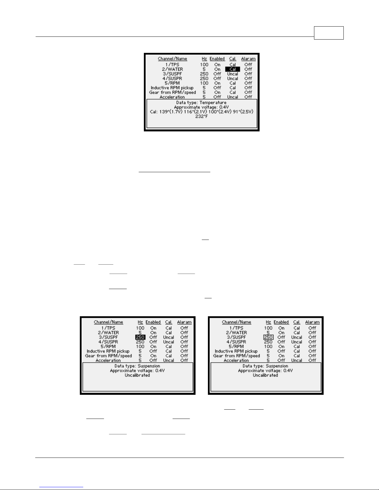
The first column is the channel number and name of that input. Note that the last 2 items (gear
calculated and acceleration) are not connected to actual wire inputs -- they are "virtual" channels
of data which you can capture. The item "Inductive RPM Pickup" corresponds to a wire wrapped
around a spark plug on the BLUE WIRE OF CABLE "A".
Each channel may independently be enabled (data will be captured) or disabled. Even if a
channel is disabled for capture, it will still display current values on the various screens if it is
properly calibrated. For example, you can still see RPM on your main screen even if it is not being
captured.
Each channel has an individually configurable capture rate (see below). Depending on the type of
input, from a minimum of 5 samples per second (Hz) to a maximum of 250 samples per second
may be captured.
The Left and Right arrows move from item to item. When you are positioned at an item you wish
to modify, press Select. (As usual, press Menu to exit out of this screen.)
When you press Select, either the item will be modified "in-place", or a menu of selections will
be displayed. For example, when you change the Hz (capture rate), the "highlight" will change
from reverse to a box:
When the box is outlined, you make changes as normal - Left and Right to cycle through the
choices, Select to make that selection, Menu to exit.
When you press Select on a Channel/Name entry, you can change the type of that input. Select
© 2009 XT Racing
Page 38
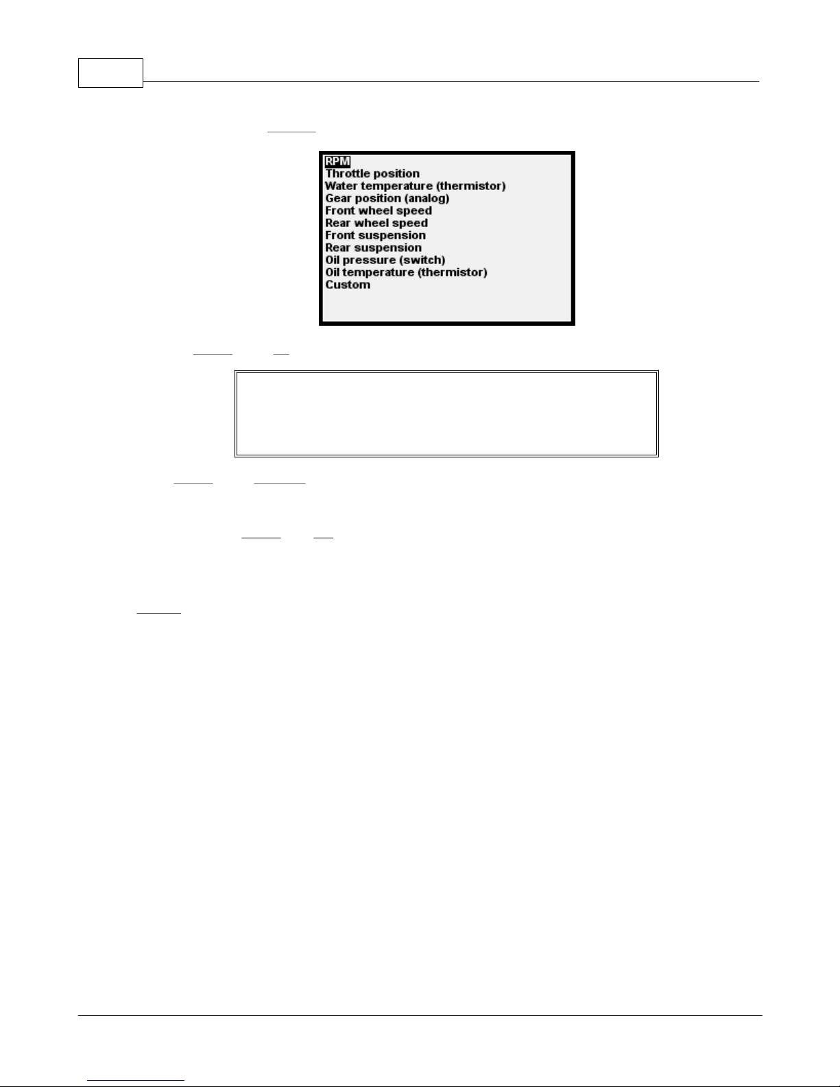
GPX Pro Manual34
from the list. Select Custom if you want to select one of the Generic types.
Pressing Select on an Hz entry allows you to change the sampling rate for that input.
You should not record data at a higher sample rate than you need
- higher sampling rates use up the memory more quickly in the
GPX and result in less time that can be stored before data needs
to be deleted.
Press Select on an Enabled entry allows you to change an input from enabled to disabled and vice
versa.
When you press Select on a Cal entry, you may then calibrate or uncalibrate that input. Each type
of data has a different calibration procedure.
Temperature- and switch-type inputs may have an alarm set. See the section below entitled
Alarms.
The lower portion of the screen shows the current value for the currently highlighted input, and
information about its calibration. Also, for analog channels, the approximate real-time voltage of
that input is shown. This voltage reading can be useful when trying to determine if you have
hooked up the input properly to the vehicle.
1.7.3 Typical Inputs
1.7.3.1 RPM
The GPX can record RPM data. RPM may be picked up in two different ways – either “direct” or
“coupled” (induction).
“Direct” mode requires that a signal be available on your vehicle which is a pulsed, binary logic
signal which is either generated by a Hall-effect-type pickup from a timing wheel, or is generated
by the vehicle’s engine control unit/module (ECU or ECM). Most fuel-injected engines will have
such a signal available. The signal can be as low as a 3.3-volt peak-to-peak signal, or as high as a
© 2009 XT Racing
Page 39
GPX Pro 35
12-V peak-to-peak signal. You might also use a one of the fuel-injector outputs of the ECU as the
RPM input.
NOTE: Direct connection is the most accurate and reliable method
of determining RPM.
To utilize “direct” mode, connect the GREEN WIRE OF CABLE “A” (digital input # 5) or the BROWN
WIRE OF CABLE “A” (analog/digital input # 1) to the to the vehicle’s digital tach signal.
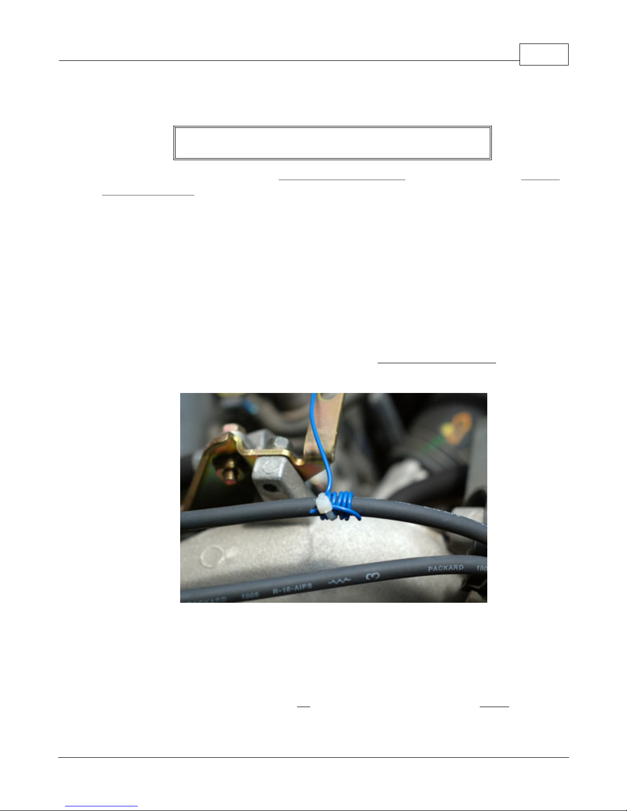
If your vehicle has no such signal, you can use the “coupled” method. This is accomplished by
wrapping an insulated wire (preferable 22-24 gauge wire) around a spark plug wire about 4-7
times and connecting that to the appropriate input on the GPX. You can check if the coupled pickup is working correctly by looking at the RPM indication on the main screen. If it is not picking up
properly, you can try a few more wraps of the wire around the spark plug wire until the RPM gets
picked up reliably.
Once the pickup is working correctly, apply a few wraps of electrical tape over the coiled wire to
hold it in place.
To utilize “coupled” (inductive) pickup mode, connect the BLUE WIRE OF CABLE “A” to the
wrapped wire around the spark plug wire.
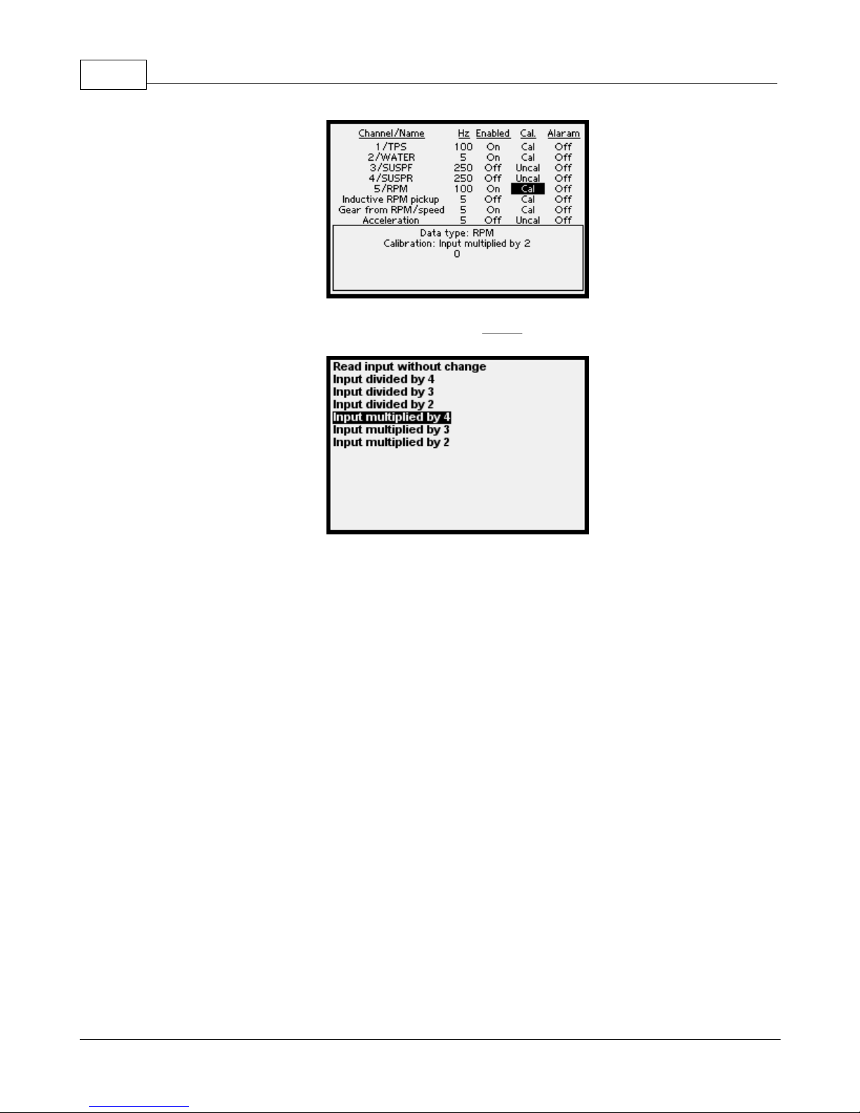
Both types of RPM, direct or coupled, may need to have the reported rpm either multiplied or
divided by 2, 3, or 4. For example, the engine might be running at 1000 rpm, but only 500 rpm are
showing on the screen. In this case the input would need to be multiplied by 2. Whether or not
this is required depends on the number of cylinders, 2- or 4-cycle engine, and type of signal you
are monitoring.
To set the multiplier or divider, go to the cal column of the RPM input and press Select:
© 2009 XT Racing
Page 40
GPX Pro Manual36
Then, use the arrows to make your choice, and press Select:
In addition, a coupled input may need to have an internal threshold value changed. This
threshold value is used by the GPX's internal circuitry for determining a valid signal. For coupled
RPM capture, you may need to adjust both the threshold, and the number of wraps around the
spark plug wire, to obtain a reliable RPM reading.
If you have more than one RPM input connected (for example, an RPM input on one of the digital
inputs, and a inductively coupled [wire-wrap] connection), the GPX will report the the RPM from
the digital input as the correct RPM. In other words, the digital input has precedence over the
coupled input.
1.7.3.2 Throttle Position
Throttle position needs two points for calibration -- the 0% throttle position (no throttle applied)
and the 100% throttle position (throttle completely applied). On most vehicles, you should do
this calibration while the vehicle is turned on, but not running (it might not be a good idea to run
full throttle in neutral!).
1.7.3.3 Temperature
Most vehicle temperature sensor are thermistors (resistors which vary resistance depending on
their temperature). These sensors need to be calibrated within the GPX at several different
temperatures in order for them to display an accurate temperature reading.
The GPX allows you to enter up to 10 different calibration points for each temperature input. If
you make a mistake, you can either delete all calibration points, or you can delete one of the
© 2009 XT Racing
Page 41
GPX Pro 37
points you've calibrated and do it again.
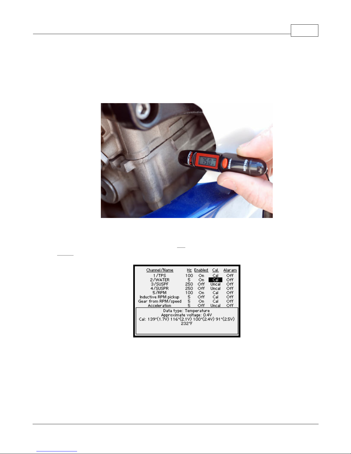
For best results, you need a small, inexpensive, non-contact infrared temperature "gun". You can
purchase one from www.xtracing.com.
You need to point the gun at a place where the coolant is circulating:
For each temperature you want to calibrate, do the following:
On the Data Acquisition screen, highlight the Cal column of the temperature input, and press
Select:
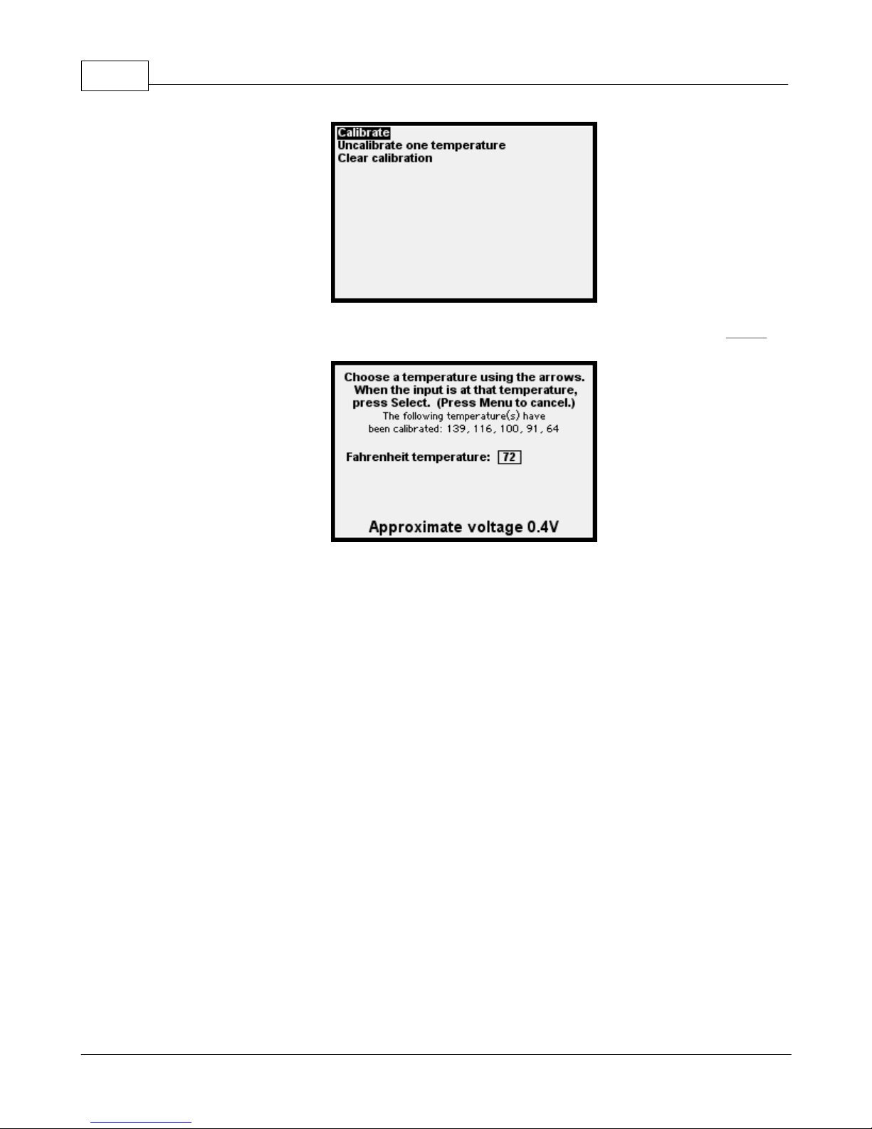
Select Calibrate:
© 2009 XT Racing
Page 42
GPX Pro Manual38
Using the arrows, select the temperature; when the "gun" reads that temperature, press Select:
Repeat this up to 10 times. You should try to get a pretty nice distribution of temperatures from
the expected lowest to expected highest temperature.
Temperature channels can have alarms associated with them. See the section on Alarms.
1.7.3.4 Gear
Gear
Vehicles that have a gear sensor (e.g., many fuel-injected motorcycles) have a gear sensor which
can be used to determine gear. This type of sensor provides an analog voltage output which is
different for each gear. To calibrate this input, you must first enter, in the menu system, the
number of gears the vehicle has (not including neutral). Then you are prompted to put the
vehicle in each gear, and neutral. This completes the calibration. The data acquisition system will
then record this input as N (neutral), or 1-6 (for example, for a 6-gear bike).
There is an alternate method of capturing and calibrating gear data if a gear sensor is not present.
You must be connected and picking up RPM data (although you do not need to capture it if you
don’t want) in order for this method to work. For this calibration, you need to drive/ride the
vehicle in each gear, and when you are going smoothly and straight ahead in each gear, press the
Select button. (This records the relationship between speed and engine RPM to determine a final
drive ratio.) It is important that the tires are not slipping.
© 2009 XT Racing
Page 43
GPX Pro 39
Be especially careful when doing this calibration – since it requires
you to read the prompts and press the Select button at the
appropriate time, while you are operating the vehicle, you need to
be extremely careful during this procedure and pay close
attention to the track and other traffic that you might encounter.
There are several limitations to note with this method:
1) if you have tire slippage, an incorrect gear might be computed (due to the engine running at a
higher rpm than normal in that gear for the speed you are travelling)
2) there is no recording of a neutral (neutral cannot be determined with this method)
3) a change in tire pressure or diameter, or a change in the gear ratio (e.g., motorcycle front/rear
sprockets), will generally require that this method be recalibrated
You have the option, via the calibration menu, of calibrating one gear at a time, or all gears at
once in succession.
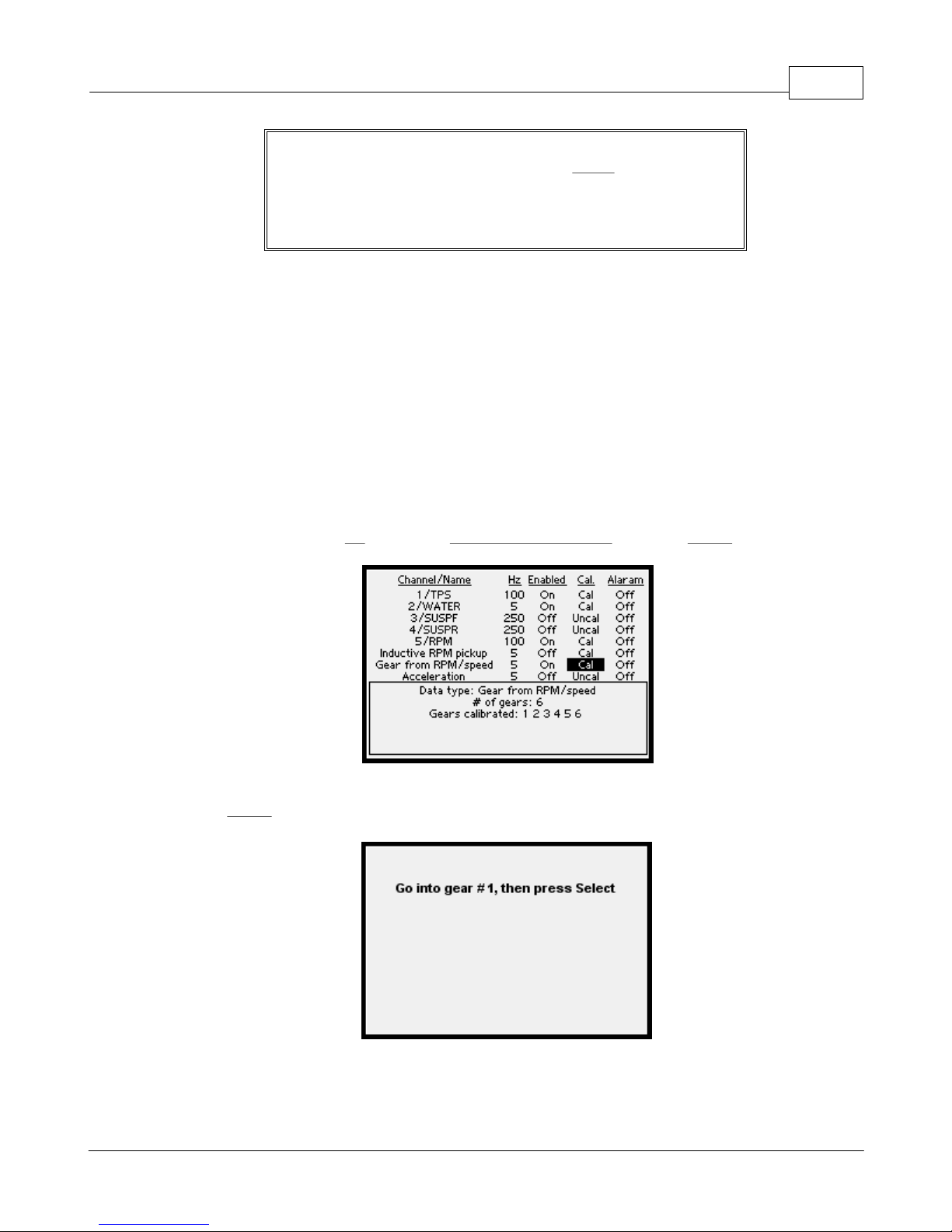
To calibrate, highlight the cal column for Gear from RPM/speed and press Select:
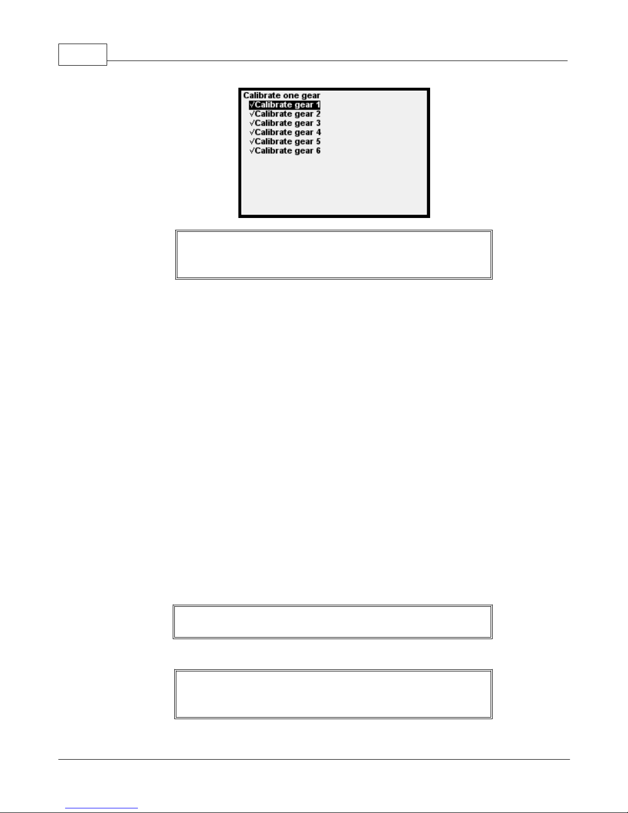
First, set the number of gears. Then, pick a gear to calibrate, get your vehicle going in that gear,
and press Select:
When you're done, a check-mark will be displayed next to each gear that is calibrated:
© 2009 XT Racing
Page 44
GPX Pro Manual40
NOTE: When you are going below about 3mph (5kph), the gear
will be reported as "N" when utilizing rpm/speed ratio to report
gear.
There is one particular advantage to using the rpm/speed ratio for capturing gears (even if you
have a gear sensor), if you are already capturing RPM: using this method does not "use up" an
analog input.
1.7.3.5 Acceleration
Your GPX is equipped with a sensitive 3-axis accelerometer. This, combined with GPS data, allows
data acquisition of G forces involved with acceleration/braking ("longitudinal" acceleration/
deceleration), and turning ("lateral" Gs). It is also used for accurate determination of the start of
some types of Point-to-point and Drag races.
In GPStudio, longitudinal Gs are as follows: >= 0G (positive numbers) = acceleration; < 0G
(negative numbers) = deceleration. For lateral Gs, negative numbers = turning to the left;
positive number = turning to the right.
Since the GPX may be mounted in any orientation, the accelerometers require calibration.
Calibration requires that the GPX be mounted securely on the vehicle, and then the vehicle be
started and stopped in as straight a line as possible (i.e., accelerated from a complete stop to a
speed, and then decelerated back to 0). The more you accelerate and decelerate during the
calibration, the better, but keeping as straight a line as possible is even more important. The
calibration will only be as accurate as this “trial run”.
You must reach a top speed of at least 7 mph for the calibration to
be successful.
NOTE: any re-positioning of the GPX on the vehicle (even in a
slightly different orientation) requires accelerometer re-
calibration.
© 2009 XT Racing
Page 45

Since the accelerometers are highly sensitive, it is important that for accurate readings, the GPX
be mounted FIRMLY on a SOLID part of the vehicle.
1.7.3.6 Wheel Speed
The GPX can acquire wheel speed data on either channel 1 (digital/analog) or channel 5 (digital
only).
In order to acquire wheel speed, the wheel needs to have a hall-effect (magnetic) or similar
pickup which determines the rotational speed of the wheel. (Another example might be an
infrared or laser source which gets "interrupted" by a disc with holes that is mounted to the
wheel.)
(A simple example is the bicycle computer. It consists of a magnet attached to a spoke of the
wheel, and a "pickup" which detects the magnet passing by.)
GPX Pro 41
Do not mount the GPX to a surface that is subject to excessive
vibration or movement.
To increase accuracy, the more "pickup spots" you can utilize on the wheel, the better. The
pickup spots should be as evenly spaced around the wheel as possible.
The pickup must output a digital signal of at least 0-5V amplitude, up to 0-12V amplitude.
The GPX supports from 1 to 99 pickup points per wheel speed input.
In addition, you must enter the circumference of the tire, in millimeters. The more accurate you
can determine that circumference, the more accurate the results will be.
1.7.3.7 Suspension
The GPX can acquire suspension data on any of the analog channels.
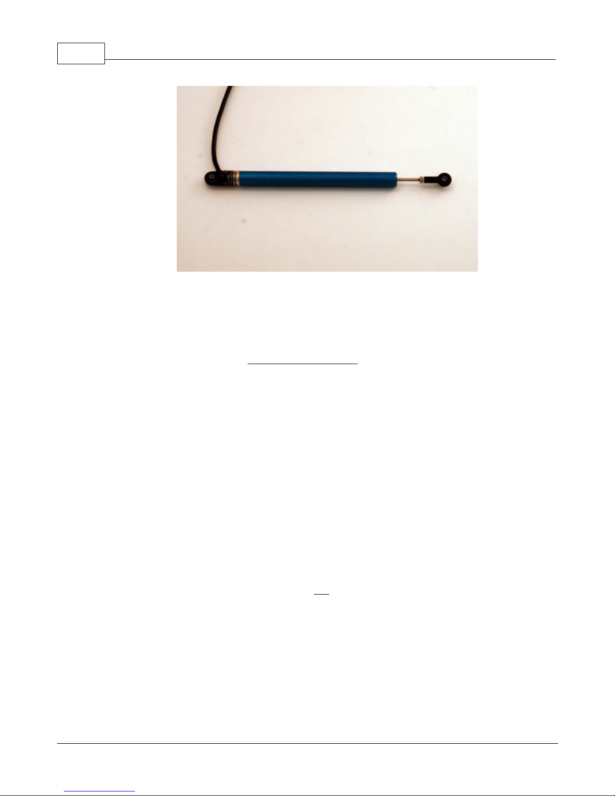
Suspension is usually determined from a linear potentiometer, which basically is a sliding
resistor.
© 2009 XT Racing
Page 46
GPX Pro Manual42
A typical linear potentiometer has 3 wires -- positive voltage, ground, and the output signal.
Depending on the extension of the slider, the output signal's voltage will vary continuously
between the positive voltage and ground.
For the GPX, the positive voltage should be connected to a voltage between +3V and +5V. A
convenient source of +3V is the RED WIRE OF CABLE "B".
Basic calibration of the potentiometer involves measuring the voltage when it is fully
compressed, measuring the voltage when it is fully extended, and specifying how many
millimeters of travel the slider moved from the fully compressed to the fully expanded position.
You may perform this calibration either before it is mounted to the vehicle, or after it has been
mounted.
If you calibrate it before it is mounted, you will be measuring the full travel of the device. That is
OK, but it does not tell you what the limits of travel are when it is mounted on the vehicle. It may
not be possible to fully extend and compress the potentiometer when it is vehicle-mounted.
Make sure you choose a potentiometer that has more travel than can occur when it is mounted.
Otherwise, the vehicle may compress or extend it beyond its physical limits and will probably
destroy it.
There is an optional calibration setting, called sag, which you may calibrate if you wish. This
calibration point represents the "at rest" (neutral) position of the slider. This is always done after
it is mounted on the vehicle, and should be calibrated with the rider/driver in position in the
vehicle. When the sag is calibrated, GPStudio can indicate when the suspension travel is
compressed or expanded, and how much, relative to this neutral position.
1.7.3.8 Switch Input
A switch input may be connected to any of the analog channels. It is an input which only can be
"on" or "off".
© 2009 XT Racing
Page 47
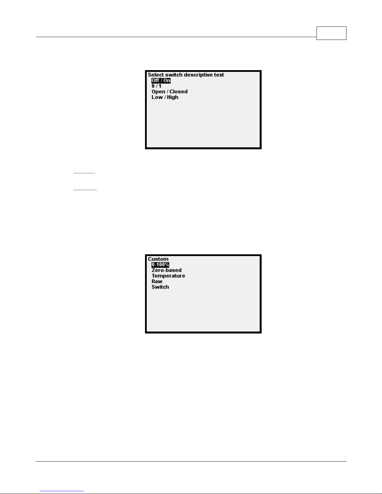
GPX Pro 43
You can specify what text you want displayed:
In addition, you can specify the polarity of the text:
Normal polarity means the first text item is displayed for a low voltage, and the second item
for a high voltage.
Reverse polarity means the first text item is displayed for a high voltage, and the second item
for a low voltage.
A switch input can have an alarm associated with it. See the section on Alarms.
1.7.4 Generic Types of Inputs
If you select Custom as the type of DAQ input, you have a choice from the following menu:
1.7.4.1 0-100%
A 0-100% input is an input which gets calibrated at 0% (its minimum value) and 100% (its
maximum value). This is similar to throttle position. See that section for more information.
1.7.4.2 Zero-based
A zero-based input is a generic input which has a base value (0 point). Only that point gets
calibrated.
The value displayed and used in GPStudio will be an arbitrary number above or below this 0point, depending on whether the voltage is higher or lower than the calibration point.
© 2009 XT Racing
Page 48
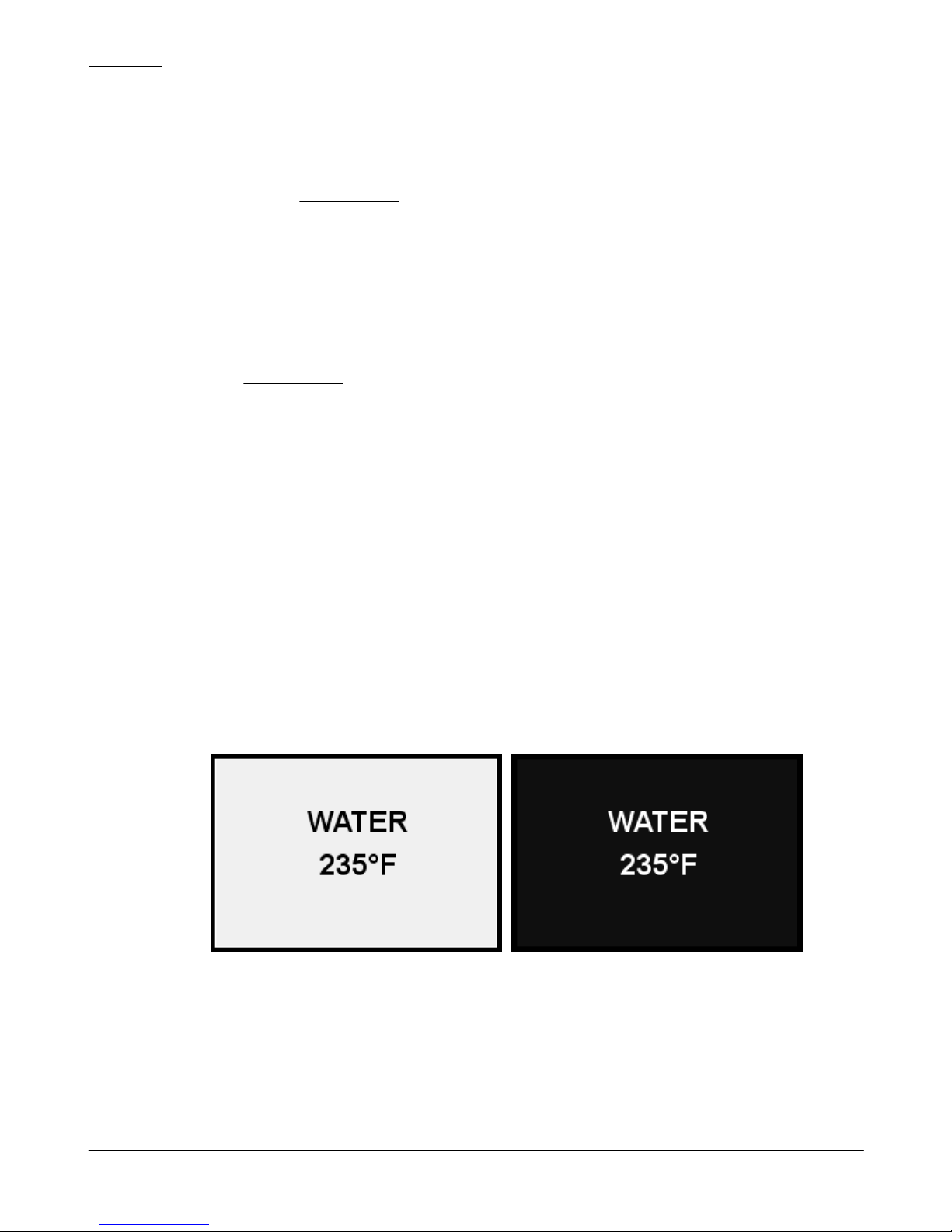
GPX Pro Manual44
1.7.4.3 Temperature
This is for calibrating a thermistor input, with up to 10 calibration points. See the section on
Temperature under Typical Inputs for more information.
1.7.4.4 Raw
A Raw input has no calibration at all. It merely reports a number from 0 to 1023, where 0
represents 0 volts, and 1023 represents about 5.0 volts.
1.7.4.5 Switch
A switch input can have only one of two values (essentially, on or off). See the section on Switch
Input under Typical Inputs.
1.7.5 Alarms
Temperature and switch inputs may have alarm(s) associated with them.
For a temperature channel, you may have one or two alarms set: one alarm may be set for the
temperature exceeding a specified temperature, and another may be set for the temperature
falling below another specified temperature.
For a switch input, you can specify that the alarm occurs either when the switch is at a low voltage
(below the calibration voltage) or a high voltage (above the calibration voltage).
Alarm conditions will cause notification on either the main screen of any of the modes, or during
the running ("spinner") screen for Circuit and Point-to-point modes. (An alarm will not occur
during a drag race since the race lasts such a short period of time.)
When an alarm condition occurs, the screen will flash with the channel name and the value:
The screen will flash between its normal display and this alarm condition as long as the alarm
condition occurs.
1.7.6 General DAQ Notes
When you change the type of an analog channel, all parameters will default to a default state, and
© 2009 XT Racing
Page 49
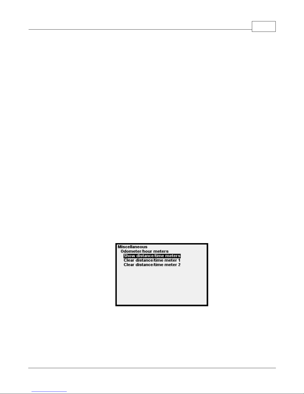
GPX Pro 45
the name will be changed to “INPUT 1”, for example.
When you change the type of analog channel, it will automatically be “de-calibrated” (i.e., there
will be no calibration set for that channel). When a channel is not calibrated, that channel will
not be captured, even if it is enabled. The channel must be calibrated in order for data
acquisition to occur for that channel. (There is one exception to this rule: if a channel is defined
as type “raw”, it cannot be calibrated, but even so, it is captured if enabled.)
When you change the descriptive name of an analog channel, if the name has been defaulted to
(e.g.) “INPUT 1”, then on the first key press the name will be cleared to allow entry of the new
name.
You may “de-calibrate” (i.e., remove calibration information for ) an analog channel. The primary
use for this would probably be for a temperature-capture channel, where many calibration points
are set. So, for example, if a mistake is made in the calibration for a temperature channel, since
an individual temperature-point cannot be deleted, you must delete all calibration information
for that channel, then re-calibrate.
Don’t worry if you mess up a calibration – you can re-do a calibration at any time.
If a channel is not calibrated, its value will display as “-“.
1.8 Time and Distance Meters
The GPX has two internal time and distance meters. These each keep track of the active time and
distance the vehicle traveled, whenever the GPX is receiving a valid GPS signal.
The two meters are independent of each other, and either may be cleared at any time.
© 2009 XT Racing
Page 50
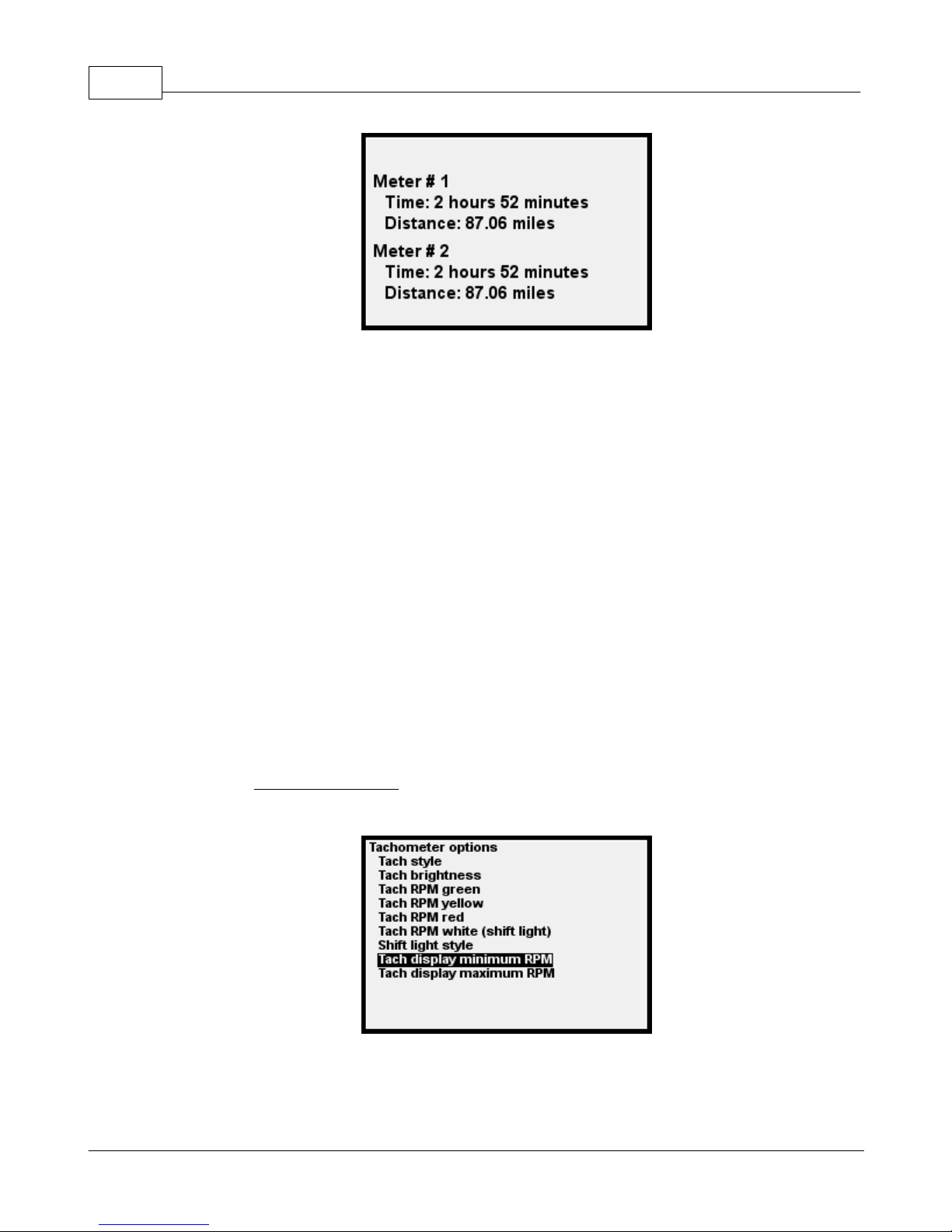
GPX Pro Manual46
1.9 Miscellaneous Information
1.9.1 Tach LCD display and LED/Shift lights
Tach LCD display
If you are connected to an RPM input, you have several different ways of displaying the current
RPM.
On any main screen or running ("spinner") screen, you may display the RPM as text (e.g., 11200 or
11.2K). You can of course customize the size and position of this text via GPStudio.
Also, on any main or running screen, you may display the RPM as a graphical "tach bar" on the LCD.
Again, you can control the position and size of this tach bar with GPStudio.
In addition, for the tach bar, you can select the minimum and maximum RPM that will show. For
example, when racing, you may only be interested in the range of 8000 to 14000 RPM. In the
menus under Tachometer options, you will see the two menu items that allow these values to be
modified:
When you make a change to the minimum or maximum, you will see a sample display:
© 2009 XT Racing
Page 51
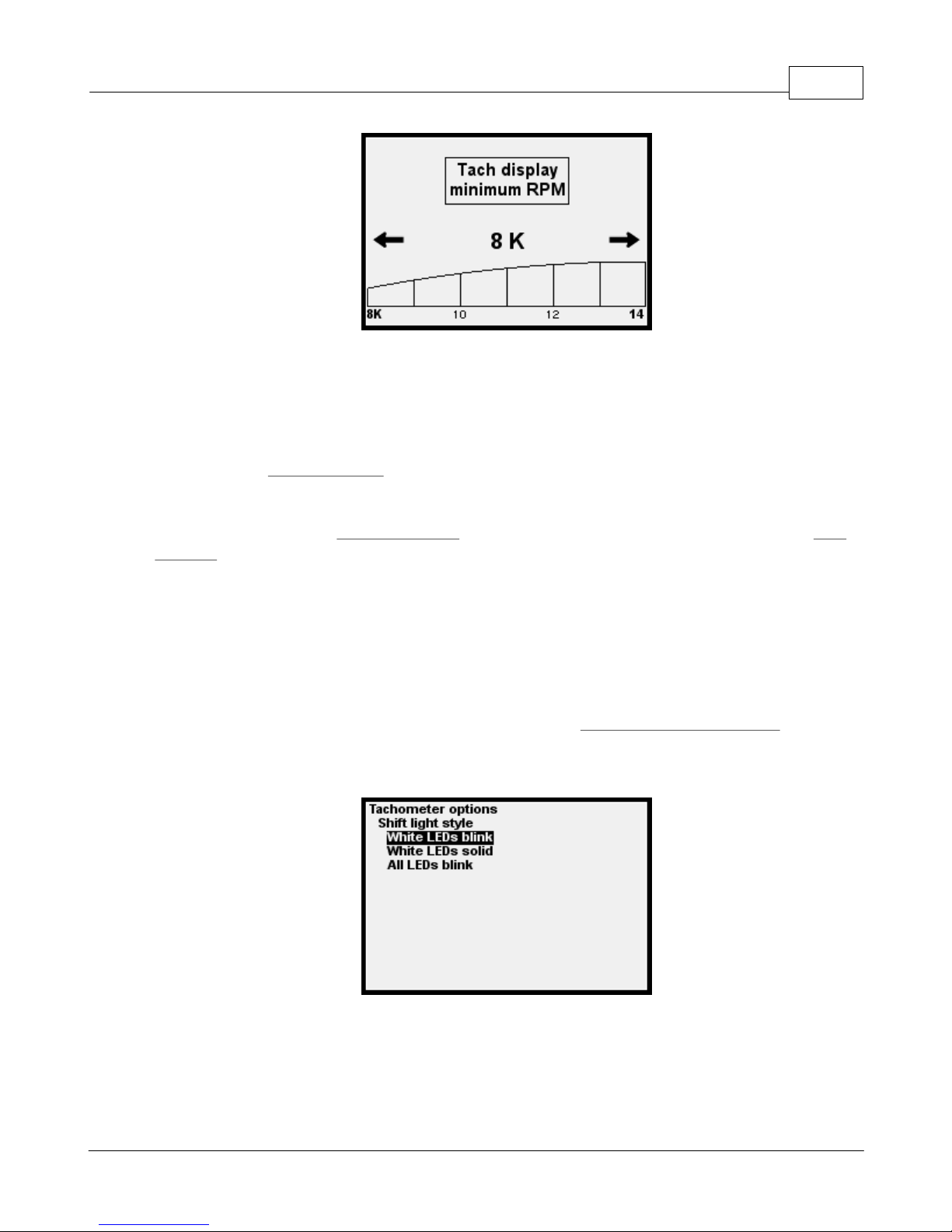
GPX Pro 47
Tach LED lights
You can also display tach information on the LEDs at the top of the GPX. The RPMs that "trigger"
these lights can be different from what is displayed on the tach bar graph.
The menu item Tach RPM green is the RPM at which the green LEDs turn on. Below this RPM, no
LED lights will display.
Similarly, the menu item Tach RPM yellow is the RPM at which the yellow LEDs turn on, and Tach
RPM red is the RPM at which the red LEDs turn on. You should set green at a lower RPM than
yellow, and yellow at a lower RPM than red.
The last two LEDs are white, and you specify the RPM at which the white LEDs come on ("shift
indication"). The RPM at which white comes on should be greater than red.
Shift LEDs
You have three choices when you hit the specified RPM for Tach RPM white (shift light). You can
choose to either have the two white LEDs blink or come on solid, or have all 8 LEDs flash, via a
menu item:
1.9.2 Session Number IDs
Each race in the GPX is assigned a Session ID. This is just a number that the GPX assigns to each
race.
© 2009 XT Racing
Page 52
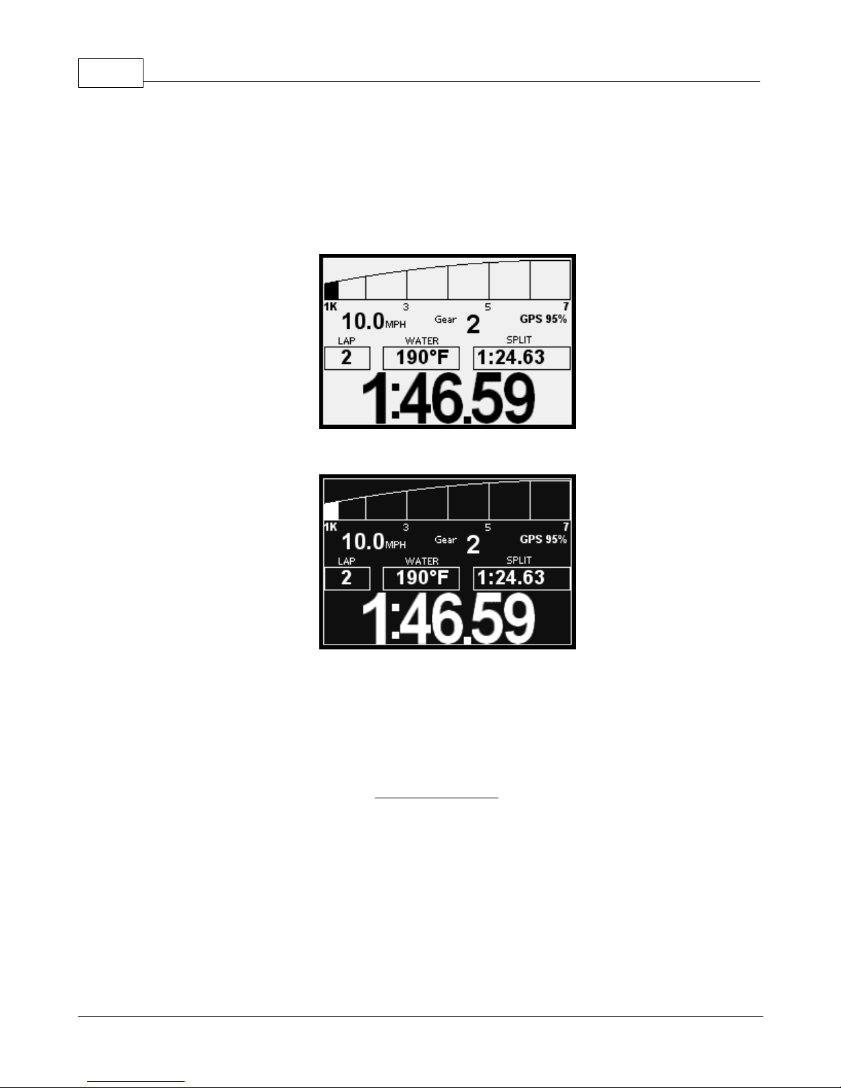
GPX Pro Manual48
1.9.3 Normal / Reverse LCD Display
You might find that in darker conditions, (e.g., night racing), that the combination of Reverse LCD
display (white display on a dark background), along with the backlight, might be a useful
configuration.
1.9.4 Backlight
When enabled, the LCD backlight brightness can be selected from 1 (dim) to 10 (bright). Since it
uses a considerable amount of power, do not use more backlighting than necessary when running
off the internal battery. Backlighting reduces the length of time the battery will hold its charge.
Select the backlight options from the LCD display options menu:
© 2009 XT Racing
Page 53
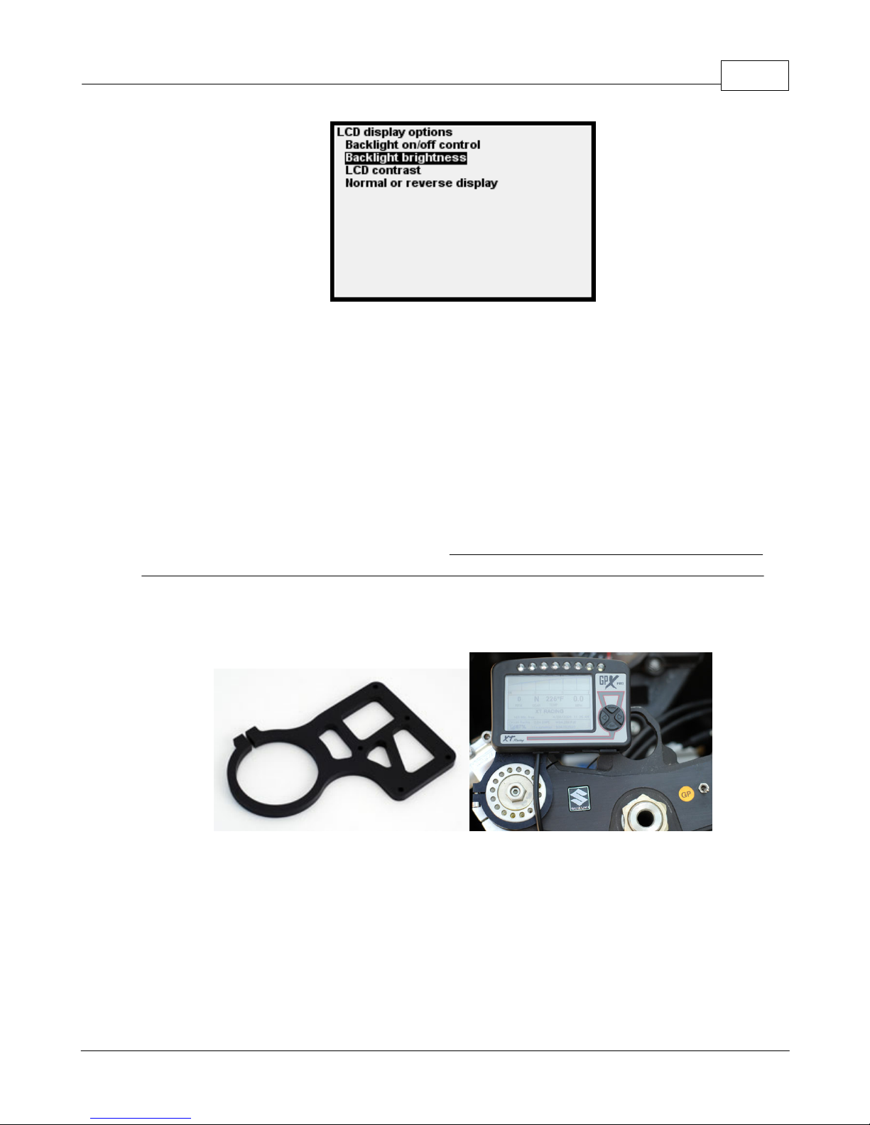
1.9.5 Mounting
The 8 tach leds are quite bright but highly directional. If you will be using the tach lights, you will
get best visibility when the GPX is mounted so that you view it head-on, as opposed to mounting
at an angle to your view.
If you will be racing at night, you may find that the tach lights are too bright, even at the lowest
brightness setting. In this case, it is recommend that the GPX either be mounted at an angle to
your line of view to reduce the apparent brightness, or turn off the tach lights altogether.
GPX Pro 49
There are 4 threaded brass inserts on the back of the GPX. These screws are metric M3 threaded.
If you mount the GPX using these brass inserts, make sure that the length of M3 screw that you
are using is not so long that it could potentially "break through" into the inside of the GPX case.
For many motorcycles, a custom anodized billet aluminum mounting bracket is available from XT
Racing at www.xtracing.com.
1.9.6 Time and Time Zones
GPS reports its time as UTC time (which is essentially Greenwich Mean time). Your local time will
probably vary from UTC time by a number of hours. For example, during non-Daylight-Saving
time in the U.S., the eastern time zone is UTC time – 5 hours. (There are some places where the
difference may be in 30- or even 15-minute increments – for example, Nepal is UTC + 5:45.)
The GPX has a menu item which allows setting the local time. It uses the UTC time as reported by
© 2009 XT Racing
Page 54
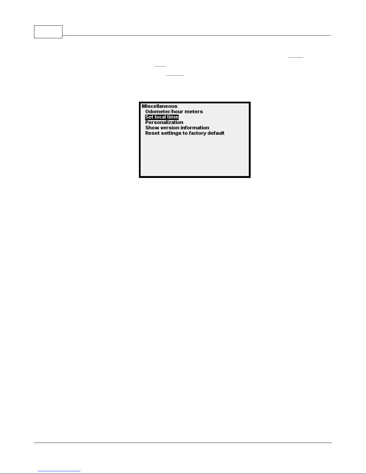
GPX Pro Manual50
the GPS as the basis, and, using the arrows, you can increase the time of day (press Right) (UTC +)
or decrease the time of day (press Left) (UTC -) in 15-minute increments until the time shown is
correct for your local time. Then press Select to finalize your selection. This time will then be
stored with your laps, and this “difference from UTC” will remain as a setting in the GPX until you
change it.
The default main screen displays the current date and time. However, until the GPS acquires a
good signal from the satellites, "Date/time N/A" (not available). As soon as a good signal is
acquired, the display will update to the current date and time.
1.9.7 Battery and Charging
The internal Li-Ion battery, when fully charged, will usually power the device for about 4-5 hours.
(This time may be shorter due to excessive use of the backlight or the tach lights.)
The battery is charged whenever the device is connected to a 12V source through the external
cable, or whenever it is connected via the USB port.
A full charge takes about 8 hours.
When connected to USB, the GPX will not automatically power down.
You may use any USB charging device (e.g., cigarette lighter, plug-in wall transformer) to charge
the GPX that is capable of supplying 400 milliamps (ma) of current.
On the default main screen, you will see a battery status indicator. When the GPX is powered by
battery alone, the display will show an approximation of battery charge left (100% = fully charged,
0% = completely discharged).
When the GPX is powered by either a USB connection or a 12V vehicle connection, the display will
show the approximate charging voltage to the battery. The GPX is generally pretty close to fully
charged when that voltage is around 4.0V.
1.9.8 Powering Down
The device does not power down if connected via USB only (i.e., no 12V present). Therefore, the
© 2009 XT Racing
Page 55

internal battery will be continually charged while plugged into USB.
1.9.9 Memory
Each captured session uses several “directory entries”. If there are not enough available directory
entries to store another session, a message will be displayed each time you go to the main
screen.
Also, the main screen shows information on the amount of memory available -- % free, and
minutes free. The percent free is the actual percentage of memory that is available and not in
use. The “minutes free” is the approximate number of minutes of racing time that the timer will
store based on the current data acquisition sampling rates.
1.9.10 File Maintenance
The GPX stores all of its session data, and other information like tracks and settings, in "files" in
its internal flash memory storage. (The GPX contains approximately 8 megabytes of flash
storage.)
GPX Pro 51
There are a limited number of "files" that may be stored in the GPX. For Circuit or Point-to-point
mode, approximately 100 races may be stored before the GPX memory approaches being full. For
Drag mode, approximately 130 races may be stored.
The number of bytes used up by each race depend upon the length of the race, and the amount of
data acquisition data stored. The higher the sample rates for data acquisition channels, the more
memory is consumed each second, and therefore the less total time may be stored in the GPX.
The default main screen shows the approximate number of minutes of racing time that can be
stored, based on the currently selected data acquisition settings, before the GPX memory
becomes full. It also shows the approximate percentage of free space in the GPX -- as that
number decreases toward 0, the GPS is becoming full.
When either the total amount of memory becomes close to getting full, or the number of races
nears the limit of storage, a message will pop up indicating that you should delete races
(sessions) before continuing. You will probably want to download those races to GPStudio before
deleting the races in the GPX -- if you delete them in the GPX and have not downloaded them to
GPStudio, those races cannot be recovered and are gone forever.
Delete options in Circuit and Point-to-point mode
Delete last viewed session - deletes the last session that you viewed when scrolling through
sessions. Only that one session is deleted.
Delete a track and its sessions - for this option you select a track, and that track and all sessions
(races) run at that track are also deleted. If you go back to that track, it will not recognize it as an
existing track, since you deleted it.
© 2009 XT Racing
Page 56

GPX Pro Manual52
Delete all sessions for a track - this deletes all races at a track, but does not delete the track
information (start/finish/splits).
Delete all sessions -- deletes all races in the GPX. All tracks remain.
Delete all tracks and sessions -- deletes all races and tracks.
NOTE: for all of the above delete operations, only those sessions
and/or tracks are deleted in the corresponding mode. For
example, in Circuit mode, only circuit mode races and/or tracks are
deleted; in Point-to-point mode, only point-to-point races and/or
tracks are deleted.
Delete options in Drag mode
Delete last viewed session - deletes the last session that you viewed when scrolling through
sessions. Only that one session is deleted.
Delete all sessions - deletes all Drag mode races.
1.9.11 Other Notes
The maximum lap or race time displayed is 9 hours, 59 minutes, 59 seconds. The display will
“freeze” at that point if the lap time exceeds that time.
In circuit mode, if you have the GPX turned on in your car, for example, when just driving
somewhere, once you hit the “starting speed”, it will think you are racing and begin looking for a
track or loop. The GPX will actually start storing data, but that data will be automatically deleted
when you go less than “stopping speed”, or if you travel more than 15 miles.
1.10 Introduction to GPS
The Global Positioning System consists of a constellation of satellites orbiting the earth. There
are currently 24+ such satellites in orbit. It is commonly thought that the satellites are stationary
in the sky (“geostationary”) like DirecTV or DishNetwork satellites, but this is not the case. The
satellites are constantly in motion – if they were not, there could be places on earth (imagine a
“canyon” in New York City) where reception could be essentially permanently blocked. Since
they are moving, any “outage” would only last for a little while.
If you are in a big open field, up to 12 satellites should be “in view” at any time. Depending on
cloud cover, atmospheric conditions, etc., less than 12 satellites may be “in view”. On the main
screen of the GPX, the number of satellites in view, and the relative “quality of signal” is
© 2009 XT Racing
Page 57

GPX Pro 53
displayed. You may find that positioning the GPX in a different spot on your vehicle may have an
effect on signal quality. Generally, the more “open” the GPX is to the sky, the better the
reception.
Also, as a result of the constant motion of the GPS satellites, you may find that, at the same track,
on different days, or even within the same day, you may find significant differences in the quality
of signal.
The GPX uses a sensitive internal antenna (mounted inside the GPX enclosure) as standard. If you
wish to improve your GPS signal quality pick-up, you may order an auxillary external antenna with
magnetic mount which can be positioned up to 10 feet from the GPX unit, for improved reception
(for example, it may be mounted on the roof of a racing car, or on the tail section of a
motorcycle).
The GPX requires a minimum quality of GPS signal before it can be used. It must have at least 4
satellites in view, and the EHPE (estimated horizontal position error) must be less than 5.00.
If you are interested in more detailed information about how GPS works, visit the following links:
http://sss-mag.com/gps1.html
http://en.wikipedia.org/wiki/Global_Positioning_System
1.11 Troubleshooting
· If the GPX appears be not responding, you can press all 4 buttons simultaneously to reset the
device.
Only perform the 4-button reset if the GPX is not responding. If
the GPX is in the middle of a file operation, there is a possibility
· You may need to adjust the LCD contrast for optimal display under conditions of very high and
very low ambient temperatures
· If you get a warning about "file system full" or "low on directory space", you need to clear out
some sessions in your GPX before continuing. If you want to save those sessions before
deleting them, connect up to GPStudio and download those sessions to your PC. After that,
using the File Maintenance menu option, select one of the delete options and delete some or
all sessions to free up some space.
that the file system could become corrupt.
· When you connect the GPX to your PC, it may take up to 10 seconds before you hear the "da-
ding" sound indicating that the GPX is properly connected. This is normal.
· Occasionally when you connect the GPX to the PC, you may not get a "da-ding" sound, or you
© 2009 XT Racing
Page 58

GPX Pro Manual54
might not get the normal "PC connected" message. In that case, disconnect the GPX, wait a few
seconds, and try again.
2 XTStudio
A perfect companion to the myriad functions in the GPX, XTStudio allows you to take the data
gathered on track and analyze it in detail on your Windows enabled PC. Review your sessions in
real time with your data streaming in graphs or on gauges to help isolate any trouble areas you
may have on the track.
Watch as you let off the throttle and your RPMs fall heading into a turn and compare your turn
entry with your other entries into that same turn. Watch data gathered on corner exit to see
where you were on the throttle early and where you were late, allowing you to find the lap
where you performed the best.
Customize everything from the appearance of your main screen to the data displayed while you
are out on track using XTStudio's integrated GPX display customization features.
With XTStudio, your laps come to life.
2.1 Loading sessions
Before you can use XTStudio to compare your races you will need to connect your device to the
XTStudio database and download your sessions. Every time you connect your device while
XTStudio is running the sessions currently on the device will be compared to the sessions already
present in the database. If there are any un-downloaded sessions on the device, XTStudio will
load the Session Downloader and prompt you to download your sessions. But before you can
download any sessions, device must be "linked" to your XTStudio database.
2.1.1 Connecting a device
When you connect your device to XTStudio with the USB cable, after you hear the da-ding
connection sound, XTStudio will communicate with the device for a second. After this, the status
bar in the lower right corner will switch to Connected.
If this is the first time that the device has been connected to XTStudio then the Device
Connection Setup dialog will appear. The device connection dialog will have two options. The
first option is used if this is the first device you have ever connected to XTStudio or if you want to
manage multiple physical devices (not multiple profiles on one device) with one instance of
© 2009 XT Racing
Page 59
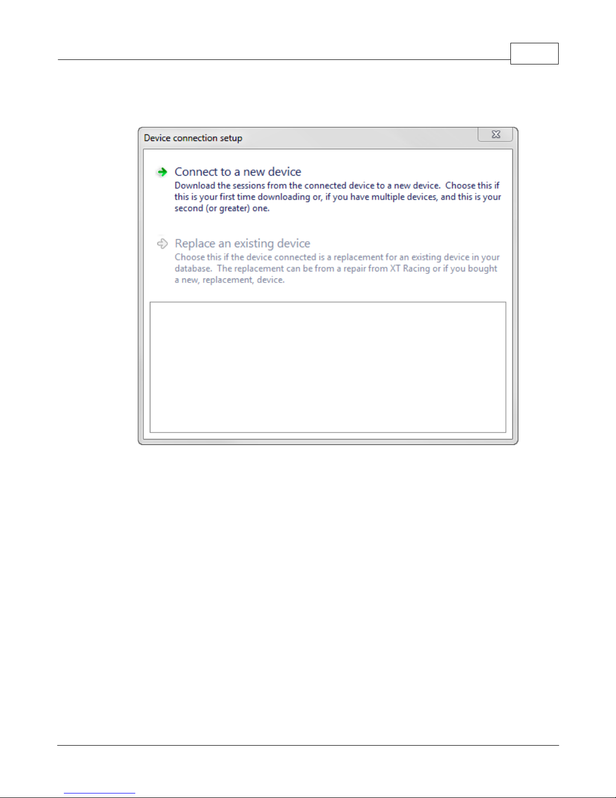
XTStudio 55
XTStudio. In most cases, simply click Connect to a new device to setup your device with the
database.
The other option is only used if the device you are connecting is a replacement (due to buying a
new one or sometimes from and authorized repair with XT Racing). In this case, you will choose
the existing database entry that this device is replacing, then click Replace an existing device.
© 2009 XT Racing
Page 60
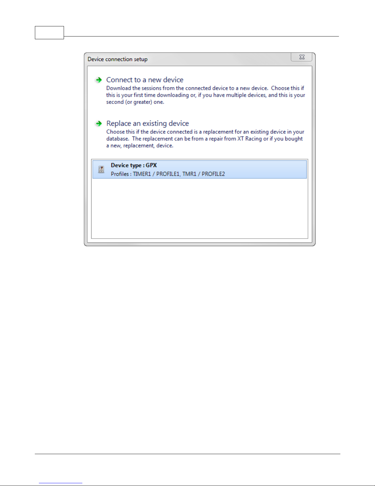
GPX Pro Manual56
2.1.2 Downloading a device
After the device is connected, the download sessions dialog will appear if there are sessions on
the device that need to be downloaded to the database.
© 2009 XT Racing
Page 61
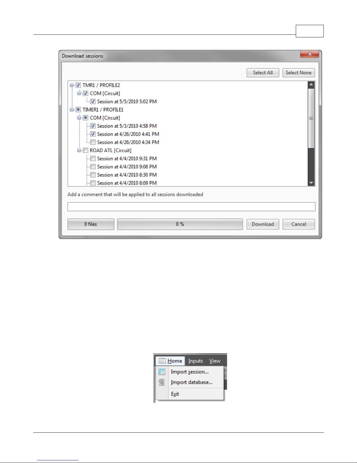
XTStudio 57
The download sessions dialog shows the profiles that contain sessions to download, the tracks
and the sessions themselves. Simply click on each one to select the sessions you want to
download or choose Select All for a quick way to download everything. If you want to attach a
comment to the downloaded sessions then enter it into the comment text box and the comment
will be added to all of the sessions downloaded at that time.
When you are ready click Download and the process will begin. Each file will move the progress
bar as it downloads. When the progress bar reaches 100% XTStudio will compute some additional
internal information so a slight pause at the end of each file is expected.
2.1.3 Importing GPStudio databases
The GPStudio database that contains your old session can be imported into XTStudio. To start the
import process choose Home -> Import database.
Next, the import database wizard will appear. On this first page, simply click the button that says
© 2009 XT Racing
Page 62
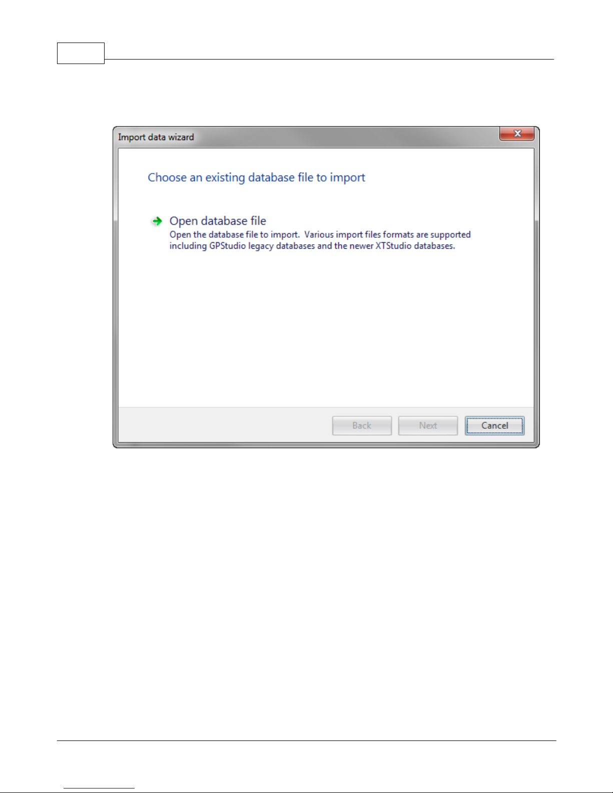
GPX Pro Manual58
Open database file and choose the old gpstudio.dat file from the file dialog (usually in My
Document\GPStudio).
After XTStudio successfully detects the data file as a GPStudio database you can click Next to
specify the destination profile to import the sessions.
© 2009 XT Racing
Page 63
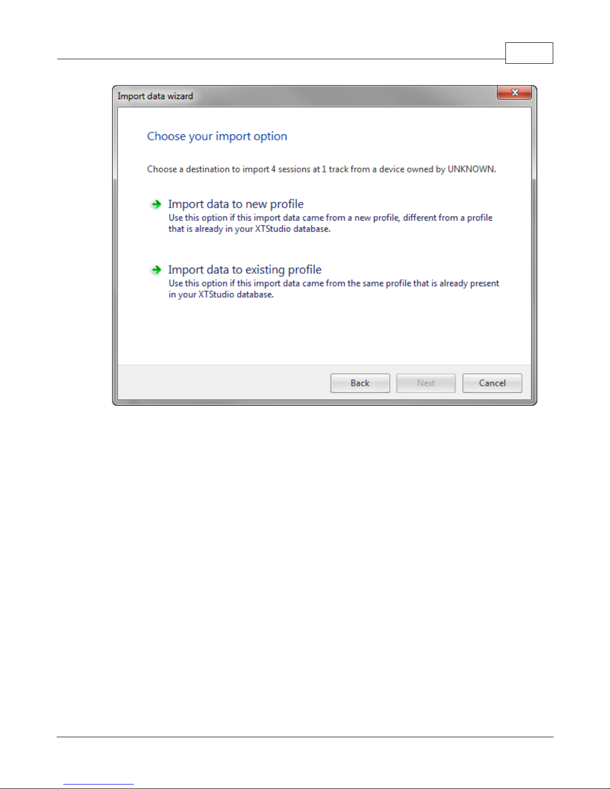
XTStudio 59
If there are existing profiles already present in XTStudio then you can attach the imported
sessions to that profile by choosing Import data to existing profile. If there are no profiles
present in the XTStudio database or you want to create a new profile for the imported sessions
then choose Import data into new profile. If you choose to import the data into an existing
profile then you will be prompted for the profile to add the sessions to. Once the profile is
selected (new or existing), the preview page will appear that tells you what is going to be
imported. Clicking Next will start the import.
© 2009 XT Racing
Page 64
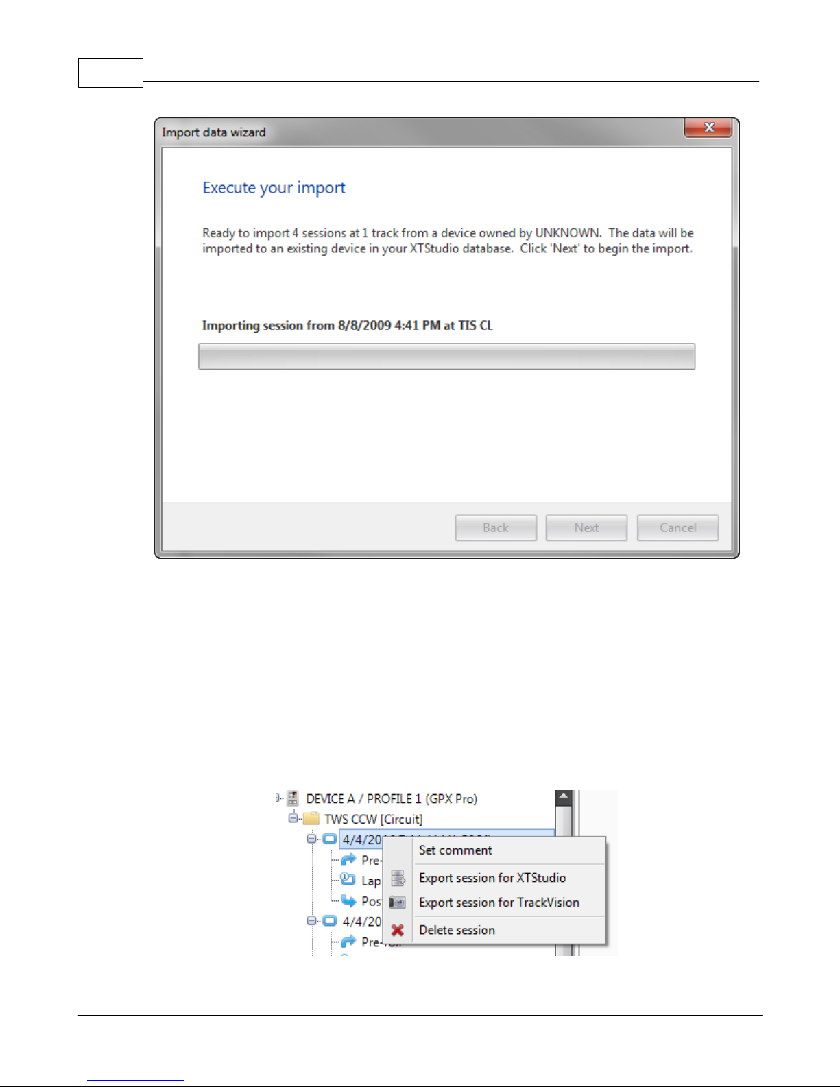
GPX Pro Manual60
Once the import is complete all of the sessions will appear in the session tree under the new (or
existing) profile.
2.1.4 Importing your friend's sessions
XTStudio allows you to share sessions with your friends. By exporting sessions from your
database and then emailing or posting them to a forum, your friends can then import the session
into their database and compare all of the available data.
To export a session right-click on the session (not a lap) in the tree and choose Export session for
XTStudio. A save file dialog will allow you to specify where to save the session.
© 2009 XT Racing
Page 65
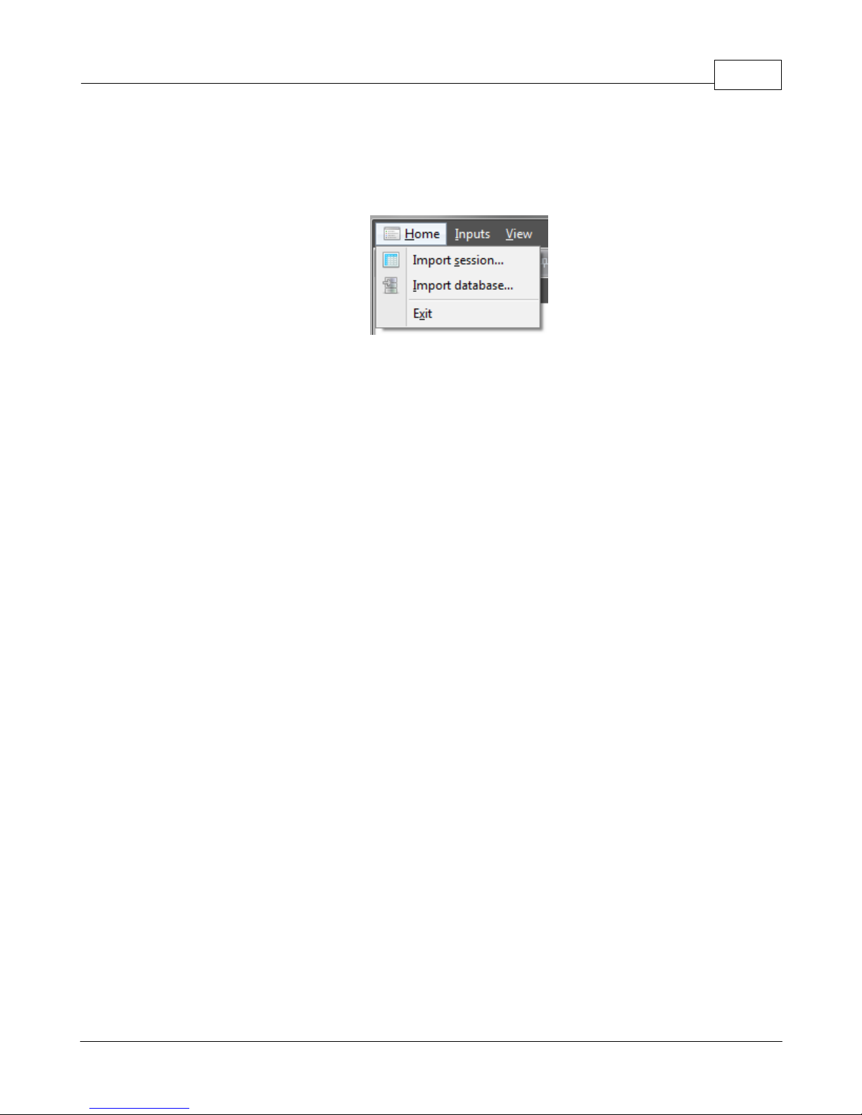
To import a session that someone sent you, you can either double-click on the file from Windows
Explorer or if XTStudio is already open then you can use the menu item Home -> Import session.
An open file dialog will appear. Browse to the received file and click open and the session will be
imported and be available from the session tree.
2.2 Database sessions
XTStudio maintains a database of all of your GPX Pro sessions that you download. Even if you
need to remove sessions from the GPX Pro because you are running out of memory, once you
download them into XTStudio, you will have them forever.
Sessions in XTStudio are stored by the track name, and the date the session took place. To make
sure that the date and time of the session is accurate it is important to set the local time of the
GPX Pro unit correctly for the track you are racing at so the date/time offset will be correct when
you download the session into XTStudio.
XTStudio 61
2.2.1 Session tree
The session management bar is the central database for storing your racing sessions. All your
devices (and profiles) will be present in the session tree. And under each profile the the track
name will appear with the type of racing mode the track is for (circuit or point-to-point). In
addition, any drag sessions you have run will appear in a folder by themselves.
© 2009 XT Racing
Page 66
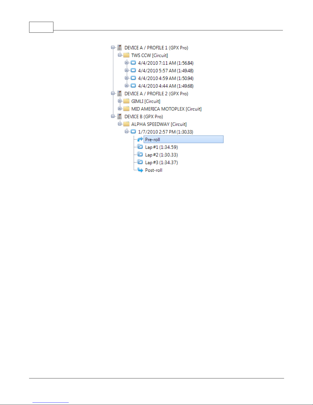
GPX Pro Manual62
Circuit sessions
For circuit tracks, each session you have raced will be displayed under the track name, and under
each session there will be an entry for each lap in that session. In addition to the laps for the
session there are two entries for pre-roll and post-roll. These are partial laps that occur before
the start/finish line and after the last lap. The post roll can be useful for analyzing data after a
crash or other reason for not completing a race.
Point-to-Point sessions
For point-to-point tracks, each session you have raced will be displayed under the track name.
Pre-roll and post-roll sections are also present for these sessions.
Drag sessions
Each drag race that you run will appear under the top-level Drag folder, and in the folder
corresponding to the type of drag race. For example a 0-30-0 on 02/20/2009 drag session will
appear as Drag > 0-30-0 > 02/20/2009.
Active Track Map
Once a lap is dragged over to a track map, the session tree will automatically hide all sessions that
are not from that same track. This makes it very easy to find a comparison lap since there will be
less items in the tree. To restore the view to all session simply remove all active laps from the
track map screen or create a new track map window with Window -> Add Track Map.
© 2009 XT Racing
Page 67
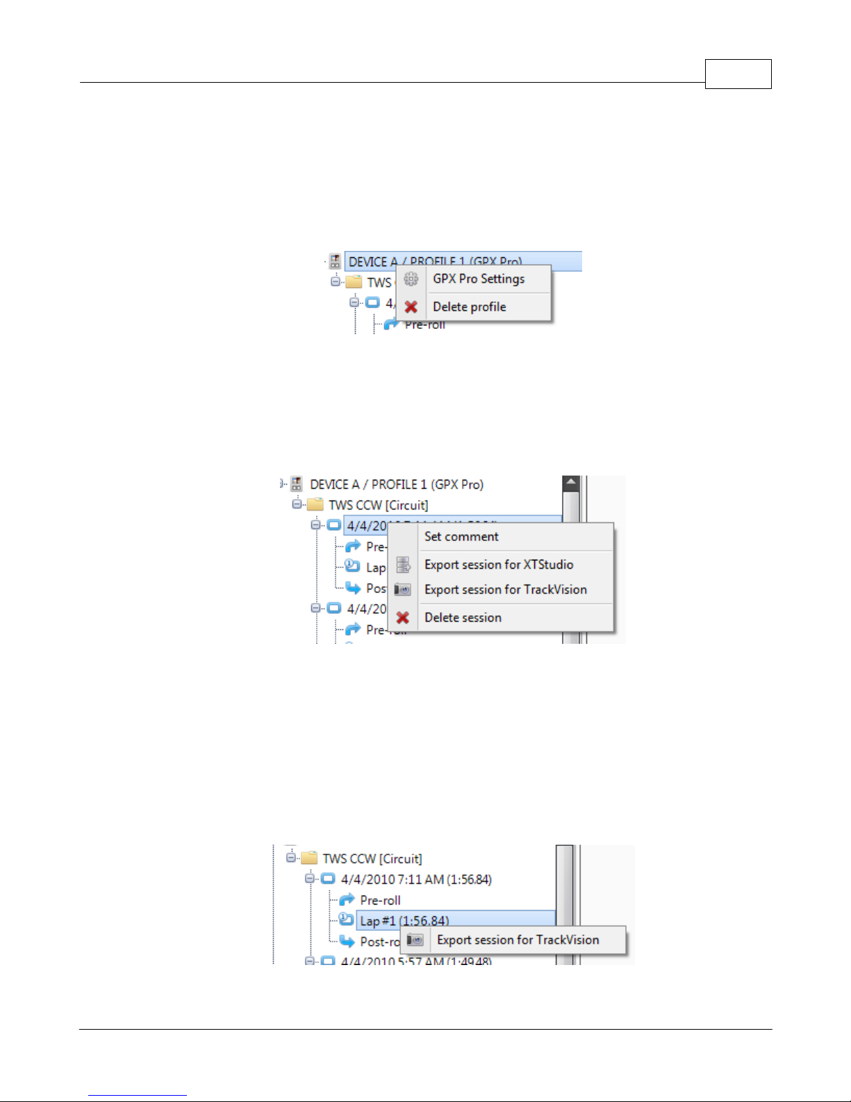
2.2.2 Session management
Items in the session tree can be right-clicked on to activate the options for that item. Each item
in the session tree will have different options in the menu depending on what is available for
that item.
Profile Options
Right clicking on a profile will allow you to access the device settings page for that device (if you
have access to that device). The device options page is typically used only by the support staff
from XT Racing if you have a problem with your device.
You can also delete a profile and all of its sessions by choosing "Delete Profile"
Session Options
XTStudio 63
Right clicking on a session will allow you to access the session options.
· Set comment - this allows you to set or change the comment associated with a session
· Export session for XTStudio - this allows you to export your session to give to your friends so
that they can compare their information with your's.
· Export session for TrackVision - this allows you to export your session for use with TrackVision
software to synchronize your data with a video
· Delete session - this allows you to delete a session from your database
Lap Options
Right clicking on a session will allow you to access the session options.
© 2009 XT Racing
Page 68
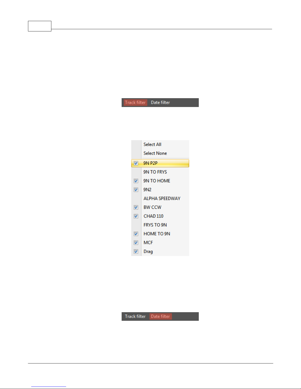
GPX Pro Manual64
· Export session for TrackVision - this allows you to export your session for use with TrackVision
software to synchronize your data with a video
2.2.3 Track filter
The session track filter allows you to hide certain tracks from the session tree without deleting
them from your sessions database. To start filtering out tracks, click on the track filter menu item
at the top of the session bar.
You can then use the options listed to add and remove tracks from display. Select All will select
all the tracks to become visible, and Select None will hide all of your tracks. In addition to these
global changes, each track can be individually hidden or shown by clicking on the track name.
2.2.4 Date filter
The session date filter allows you to hide certain sessions (based on when you ran them) from the
session tree without deleting them from your sessions database. To start filtering out sessions,
click on the date filter menu item at the top of the session bar.
You can then use the options listed to start filtering what is displayed in the session tree by the
date of the session. Each of the items listed will filter out any sessions that are not within the
date option selected. The Custom item will allow you to create a custom filter state using the
From and To entries. To change the dates in the From and To areas, just click on the down arrow
© 2009 XT Racing
Page 69
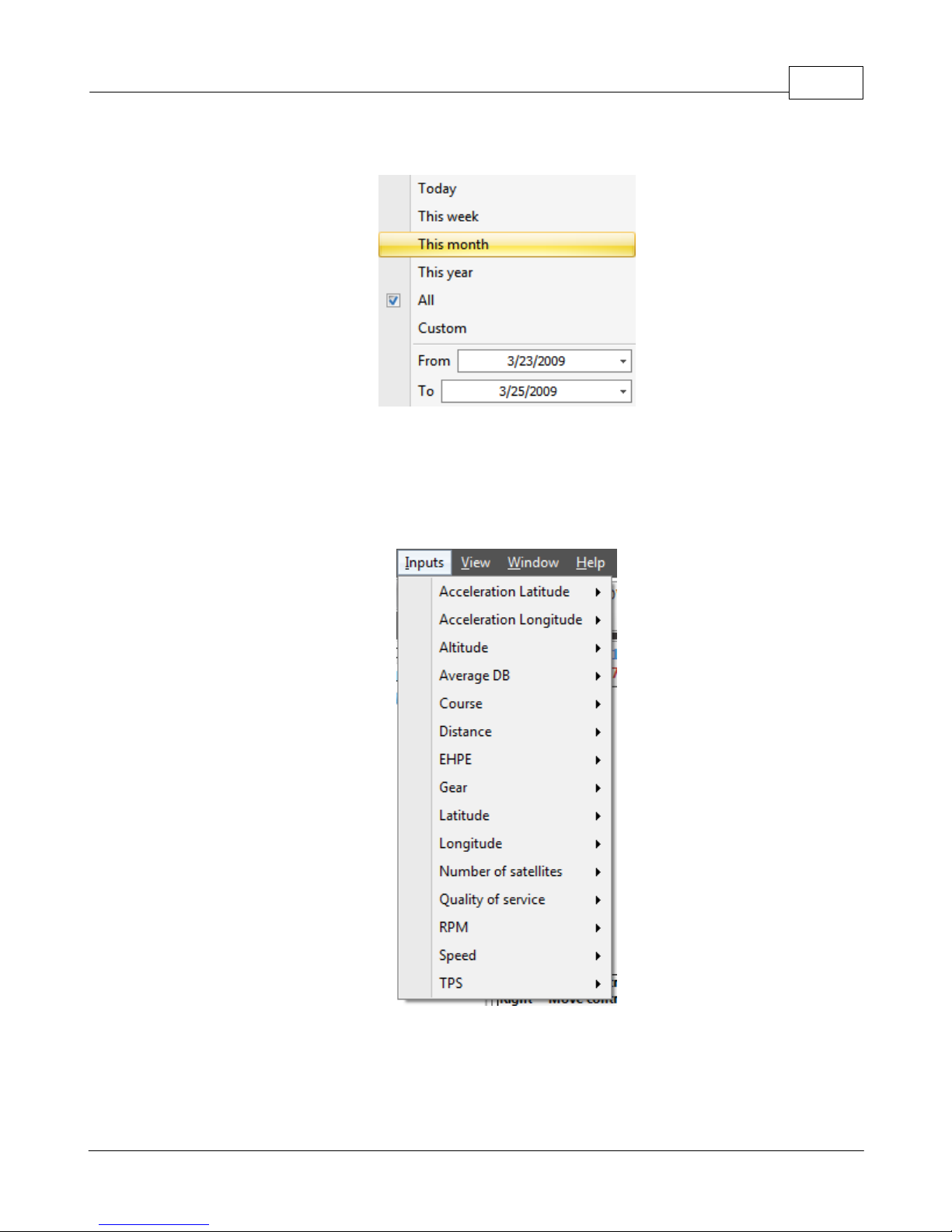
and choose the date you want, or just type the date into the box.
2.3 Input configuration
All data channels can be configured through the Inputs menu on the main menu. All of the inputs
found in the XTStudio database will be displayed here. Each input has a submenu that has the
configuration options for that input.
XTStudio 65
2.3.1 Input range
With the input menu, the minimum value and maximum value of a channel can be forced to
specific values. These minimum and maximum values are used throughout the system in all
graphs and gauges.
© 2009 XT Racing
Page 70
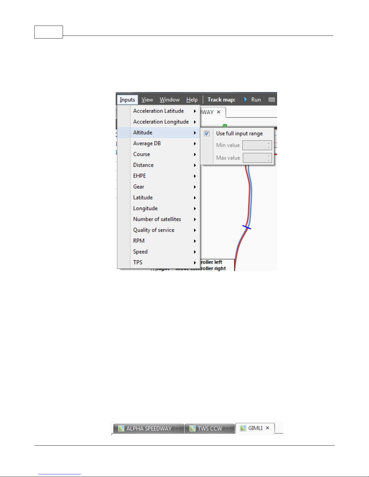
GPX Pro Manual66
The inputs can be automatically set to the full range by clicking on the Use full input range option.
By turning this option off you will have access to the number boxes that will allow you to specify
the minimum and maximum value for the input.
2.4 Analyzing sessions
The main feature of XTStudio is the analysis of your sessions. Analysis of laps or sessions is done
via the five major analysis components of XTStudio.
· Controller bar
· Track map
· Data bar
· Graph bar
· Gauge bar
2.4.1 Track map
The track map is the main window feature in XTStudio. It display the track map for all of the
current comparison items and contains the track bar which is used to control the active location
for the gauge bar, data bar and graph bars. There can be multiple track maps open at the same
time via the main tabbed interface.
© 2009 XT Racing
Page 71
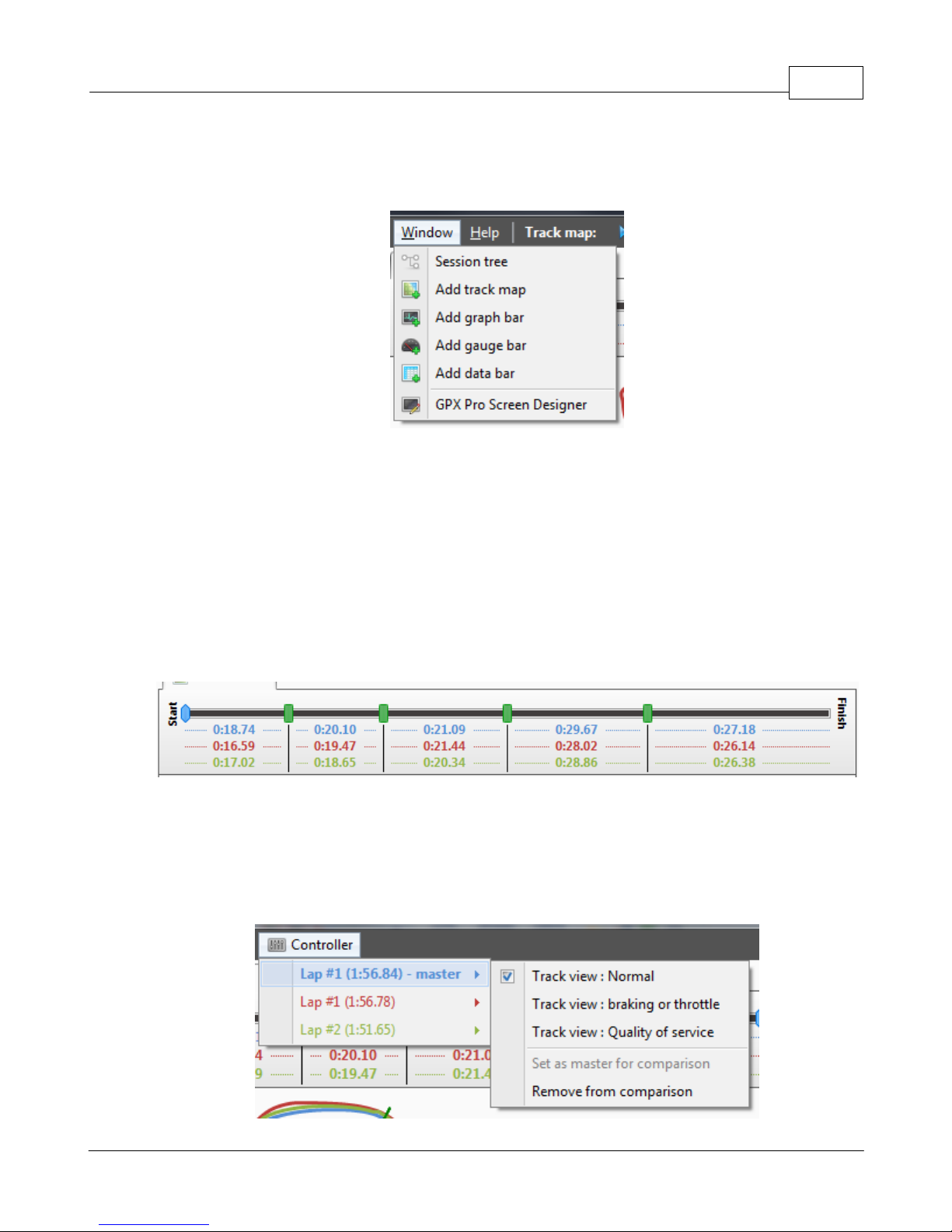
Track maps can be added by choosing Window -> Add Track Map.
2.4.1.1 Overview
To start your analysis, simply drag (or double-click on it) a lap or session from the session tree to
the track map, and that item will be added to the comparison. Each new item will be added to the
controller bar in a specific color, and that color is used throughout XTStudio to indicate that the
data, track map, graph or gauge needle belongs to that lap.
XTStudio 67
Multiple track maps as tab items
Add another track map window
The track map controller bar appears at the top of the track map. It maps the length of the track
from start to finish as a line. The markers that appear on the line are the split lines and the times
for each split section are displayed below for each of the color-coded laps.
The above picture is comparing three laps from the same circuit session. The track has 5 splits as
indicated by the green rectangles. The current location is shown with the blue marker.
The active sessions are managed through the controller menu which can be accessed on the main
menu bar under the controller item or by right-clicking on the track map.
© 2009 XT Racing
Page 72
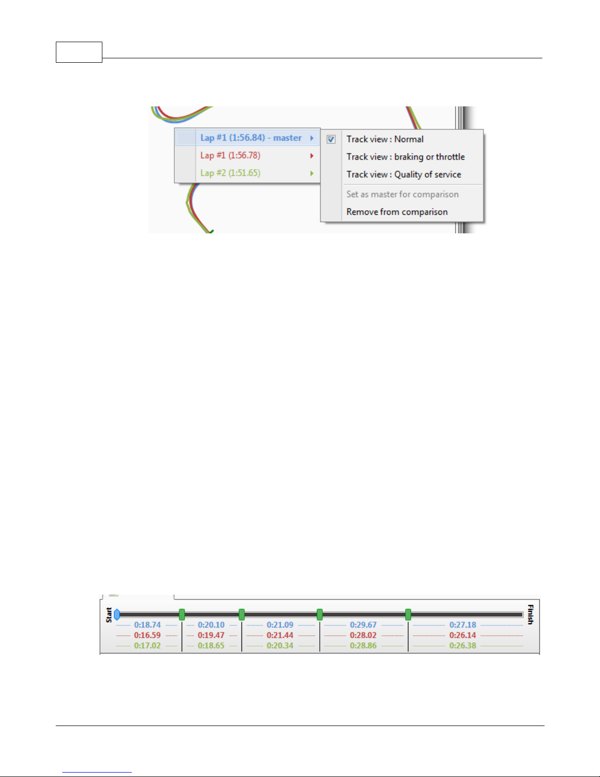
GPX Pro Manual68
Controller menu from main menu
Controller menu access from right-click
Track view items are used to tell how to draw the track map:
· Normal mode just displays the track map in the corresponding comparison item color.
· GPS quality of service displays a varying color from red (0%) to green (100%). This display can
show you areas of the track where your GPS signal quality is low. A low signal quality could
mean that you need the GPX Pro external antenna.
· TPS (or another DAQ channel name) displays the DAQ channel value from red (0%) to green
(100%). Any analog channel that is calibrated as a 0% to 100% input can be displayed using this
mode. (Only available with the DAQ channel connected and correctly configured)
· Braking or throttle displays red when you are decelerating and green when you are
accelerating. This display is useful when you want to see where on the track you got on the gas
after a turn. (Only available with acceleration calibrated and capturing).
The Set as master for comparison item sets the master lap for the comparison. The master lap is
used when you want to set your graphmodes in Graph delta to master mode. This item will set
the selected comparison item to the master. The master comparison item is indicated with bold,
underlined text in the controller bar item box.
The Remove from comparison will remove the the item from comparison.
2.4.1.2 Moving
The controller bar holds the current system location for all of the display of gauges, graphs and
track maps. The track bar at the top of the controller bar shows where you are with respect to the
start and end of the items. You can drag the handle right or left to move the system location.
In addition to dragging the track bar with the mouse to move "time", you can use the keyboard
shortcuts Left and Right keys, if you hold Ctrl, Alt or Shift while pressing the Left or Right key, you
can increase or decrease the change step to move through the lap faster or slower. You can also
© 2009 XT Racing
Page 73
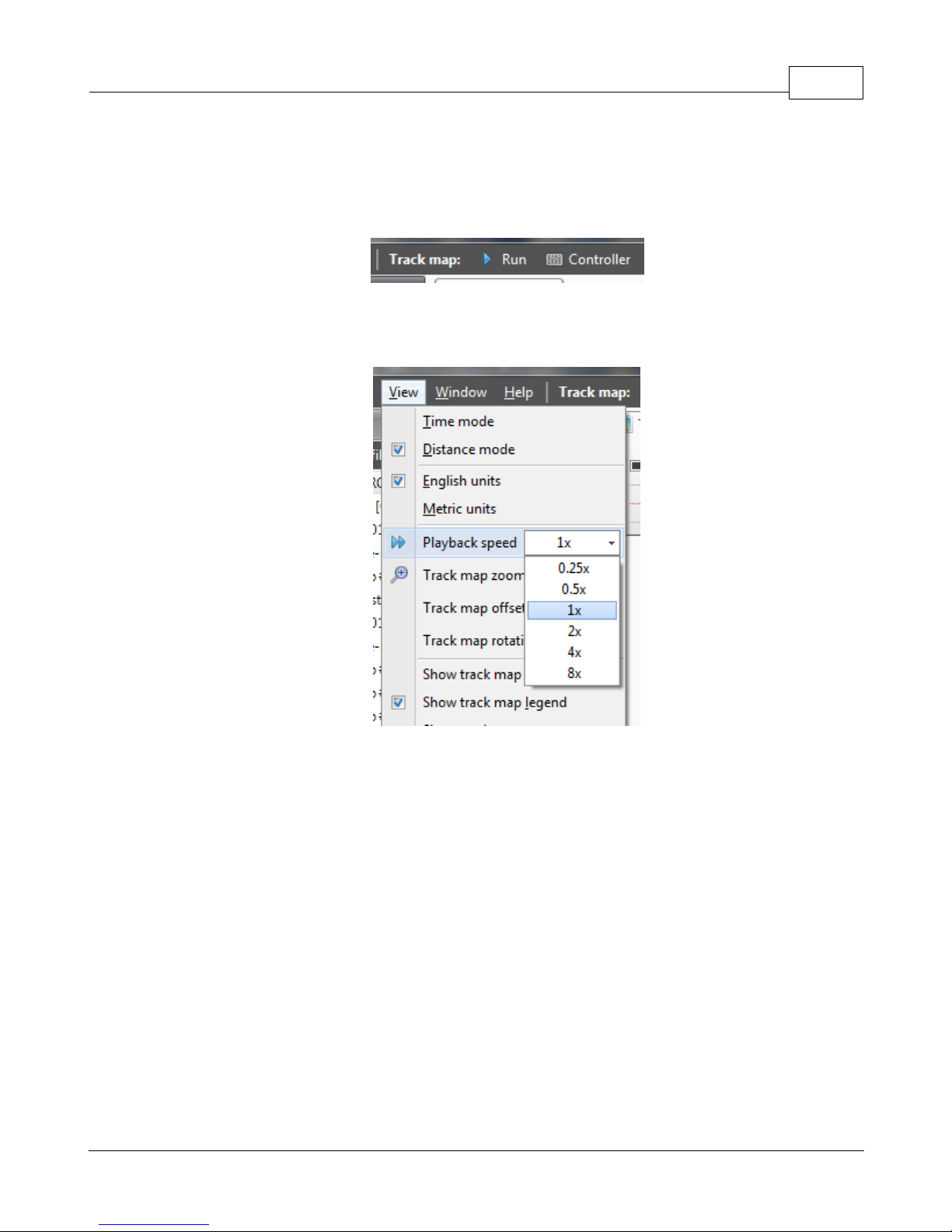
XTStudio 69
click on the track map to move the location to the nearest track point.
In addition to the manual ways to move around the track, you can also automatically run the track
by clicking the Play button in the top menu bar.
The speed of the playback can be increased or decreased with the View -> Playback speed menu
item.
2.4.2 Track map
The track map window is in the tab area of XTStudio and is where the current track map is
displayed based on the GPS data collected. The normal track map is displayed in the same color
as the comparison item it corresponds to with no track offset displayed. In addition the track map
is auto-rotated to fit correctly in the window.
© 2009 XT Racing
Page 74
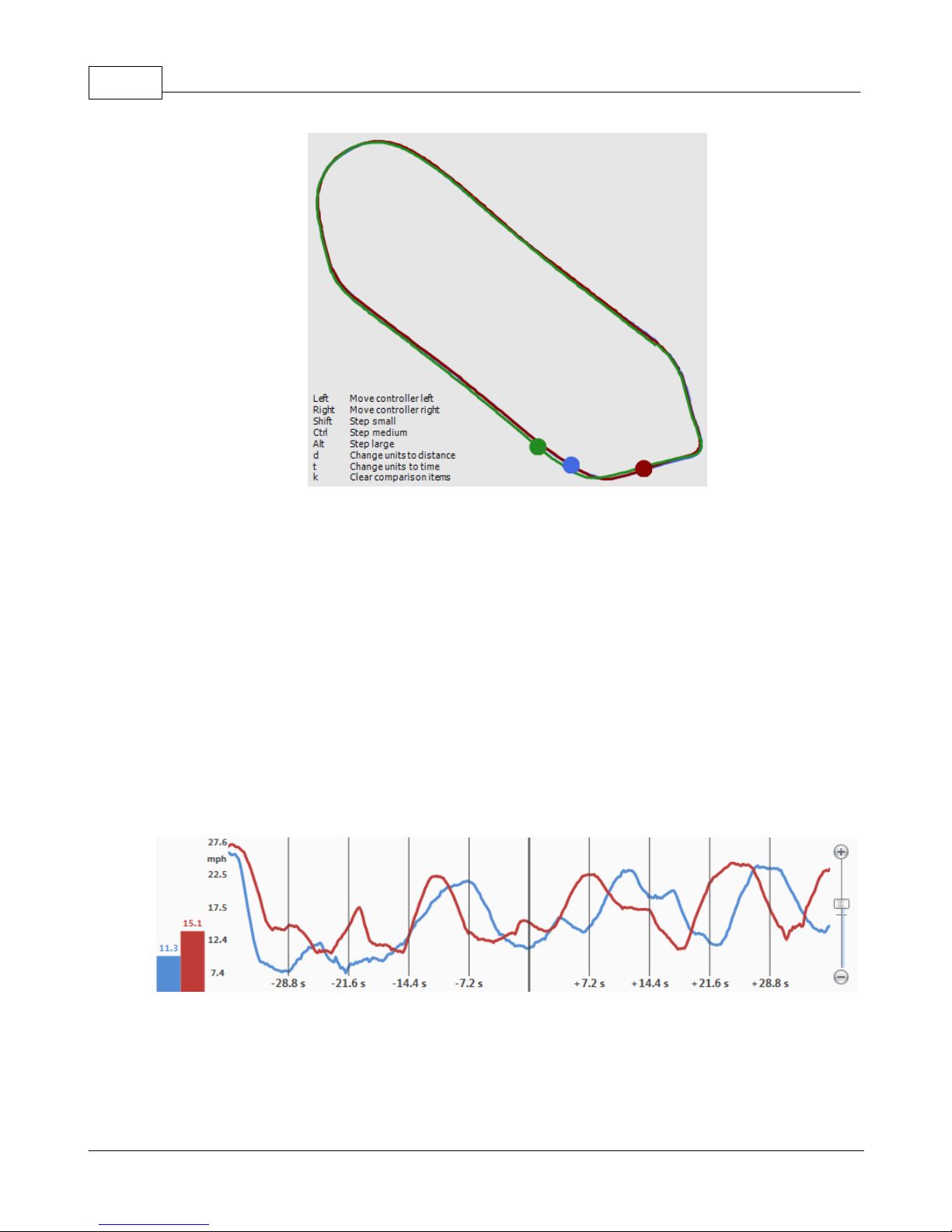
GPX Pro Manual70
The dots on the track indicate where on the track you were at the given controller distance.
2.4.3 Graph bar
The graph bar will graph data values captured with the GPX Pro. With the ability to plot multiple
laps and zoom in and out on the data, the graph bar provides a powerful tool for race analysis. In
addition, since you can add multiple graph bars to your XTStudio window, graphing multiple
variables at once is possible.
The graph bar is split up into four areas. From left to right the areas are
· Current values display
· Y-axis labels
· Value graph
· Zoom bar
The current value display shows a bar graph with the value of the input at the current system time
(or distance). The colors of the bar and the value are displayed in the normal color that
corresponds to the item in the comparison.
The y-axis values show the range of the graph and the units of the channel value.
© 2009 XT Racing
Page 75
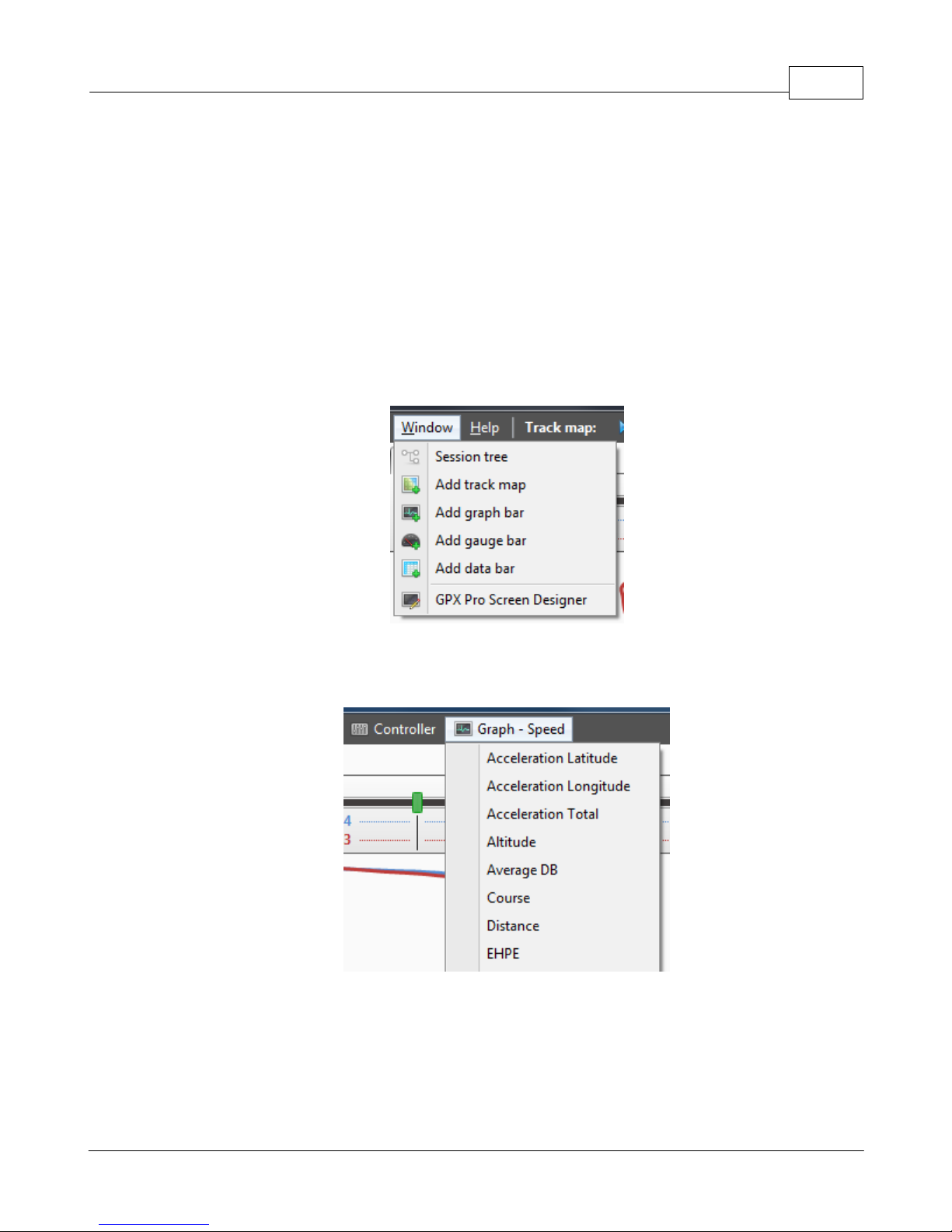
XTStudio 71
The value graph is the actual graph of the data over time or distance depending on your controller
setting. The wider center line shows the current system time. The additional vertical lines span
out as a specific time or distance plus or minus from the current time. So, moving the system time
either manually or through the replay race function will pan the graph across the center line.
Finally, at the far right is the zoom bar for zooming in and out on the graphed data. Dragging the
zoom bar up zooms into the data, while dragging it down will zoom out. It is possible to zoom all
the way out so that the entire session is visible in one view.
Graph bars can be added to the screen through the Window -> Add graph bar option in the system
settings menu.
The configuration of the graph can be access from the main menu bar or by right clicking on the
graph window.
2.4.3.1 Input
The first set of items available from the graph bar settings menu are which input to graph. The list
available to you will vary depending on how you have set up your data acquisition inputs. The
only data value that will always be available is Speed since that is provided by the GPS module.
All other data acquisition will be listed; simply click on one of them to change the current graph
© 2009 XT Racing
Page 76
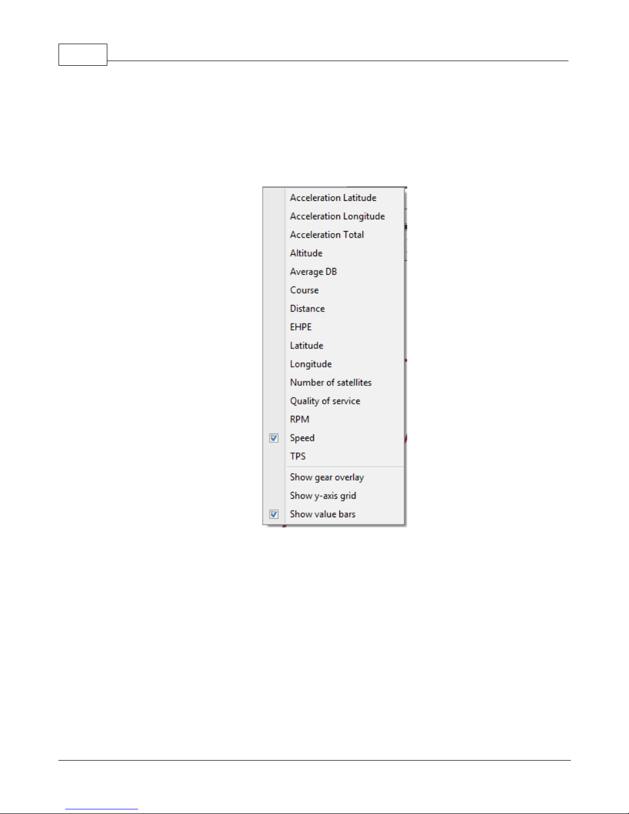
GPX Pro Manual72
input. If you have acceleration turned on and calibrated, then the acceleration data will appear as
two entries in the list.
· Accel lat - the latitudinal acceleration, which is the acceleration to the right or left of the
direction you were traveling; in other words, this is the turning acceleration
· Accel long - the longitudinal acceleration, which is the acceleration in the direction you were
traveling; in other words, this is the braking or throttle acceleration
2.4.3.2 Gear overlay
If you have a data channel calibrated as a gear input or are using the RPM gear ratio calculator
then this option will make visible the overlayed gear display. The display of gear is not limited to
taking up the whole graph area. It is an overlay that you can turn on while looking at another
input, for example RPM. This allows you to analyze your RPM and your gear changes at the same
time.
© 2009 XT Racing
Page 77
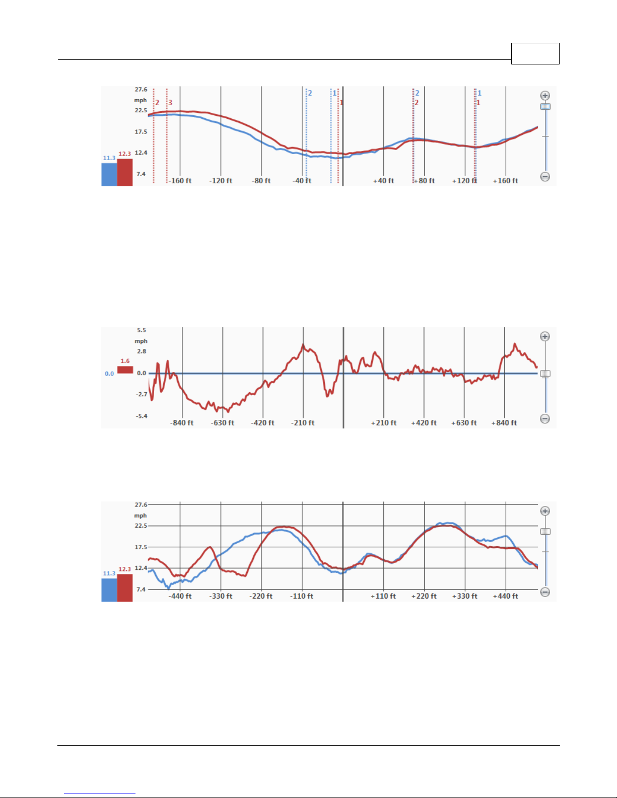
2.4.3.3 Graph delta to master
The graph bar has the ability to graph the data as a delta to the master controller item.
Remember, the master controller item is the item that is bold and underlined. The graph will plot
the difference between the current item and the master item for the input. This mode provides
you a nice overview of the exact places where you were slower on one lap versus another, for
example.
XTStudio 73
2.4.3.4 Show y-axis grid
Show y-axis grid simple adds y-axis grid lines to the graph to help line up the graph values with
the y-axis labels.
2.4.3.5 Link all chart zooms
The link all chart zooms option (in the View menu) is used when you have multiple graph bars
open in XTStudio. By choosing this option, all of the graphs in XTStudio will zoom to the same
level by moving any one of the graph zoom bars.
© 2009 XT Racing
Page 78
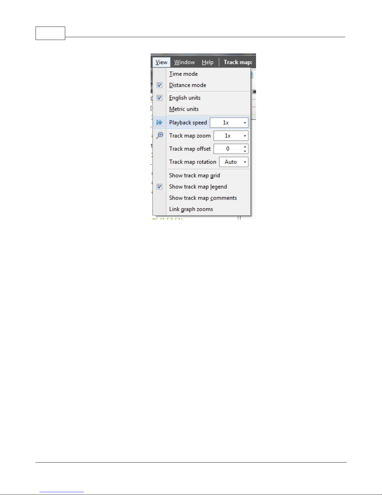
GPX Pro Manual74
2.4.4 Data bar
The data bar displays detailed information for each comparison item at the current system time.
The information includes the current time, current distance, lap time, lap distance. To add a data
bar to the screen use the menu item Window -> Add data bar
If data acquisition channels are connected and calibrated, then each of the DAQ channels will be
displayed. For each channel, the current value, maximum value and current delta value to master
comparison item are displayed.
The data bar is useful for pin-pointing to the actual numbers as you use the controller bar to move
through your laps.
© 2009 XT Racing
Page 79
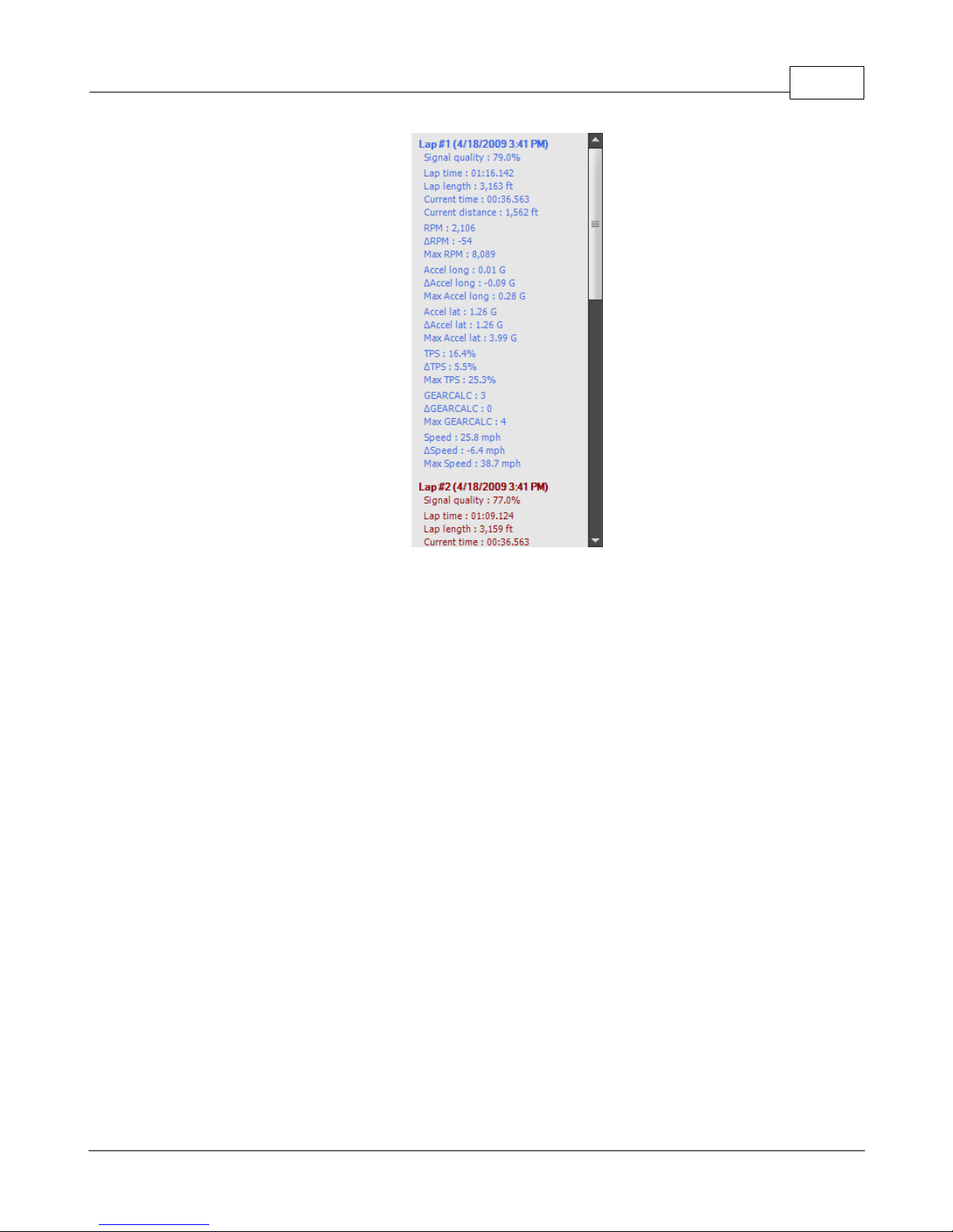
XTStudio 75
The data bar's display can be customized through the Data menu on the main menu or by rightclicking on the data bar window. Each DAQ channel can be individually turned on and off through
this menu to access only the channels you are interested in. In addition the minimum, maximum
and delta values can be display by turning on and off those options in the menu.
© 2009 XT Racing
Page 80
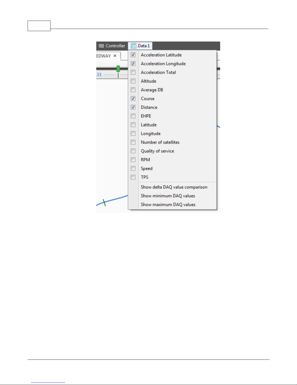
GPX Pro Manual76
2.4.4.1 Options
The track maps options are found under the View menu on the controller bar. There are multiple
options available to control the track map display.
© 2009 XT Racing
Page 81
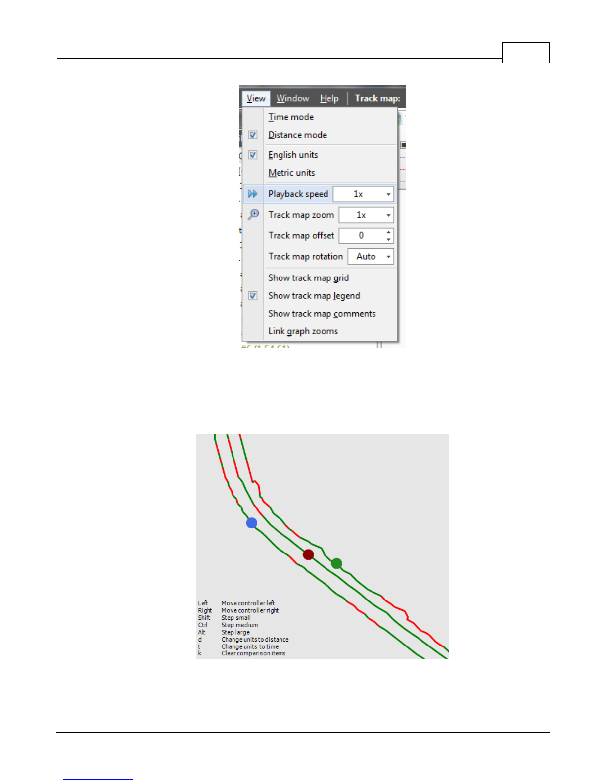
XTStudio 77
Track zoom
Setting the track zoom allows you to display the zoomed track in the window. By using this option
only part of the track around the current system time will be displayed, and as the controller
distance changes the display will be panned to keep the dots in the window.
Track offset
The track offset setting is used to separate track maps from displaying on top of each other in the
© 2009 XT Racing
Page 82
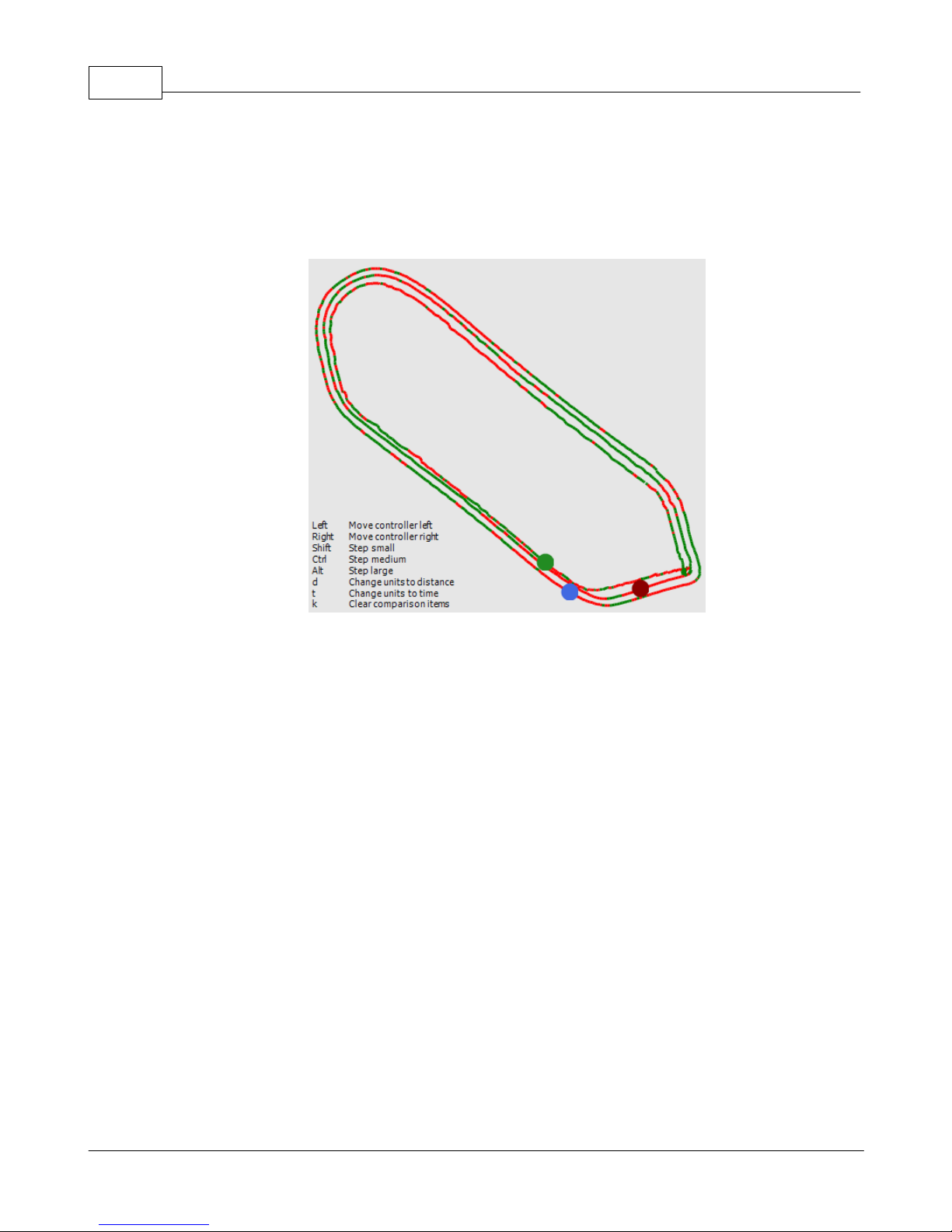
GPX Pro Manual78
window. This is used when you want to compare track map views from one lap to another. For
example, to compare where on the track you started accelerating in one lap versus another,
simply increase the offset to separate the display. For small tracks, or tracks with tight turns to
large, an offset can result in a display that overlaps itself, so set the offset carefully for accurate
analysis.
Track rotation
By changing the track rotation from auto to a specific value you can rotate the track to a specific
angle.
Show track map grid
This option will display a grid over the track map and indicate the size of the grid squares.
© 2009 XT Racing
Page 83
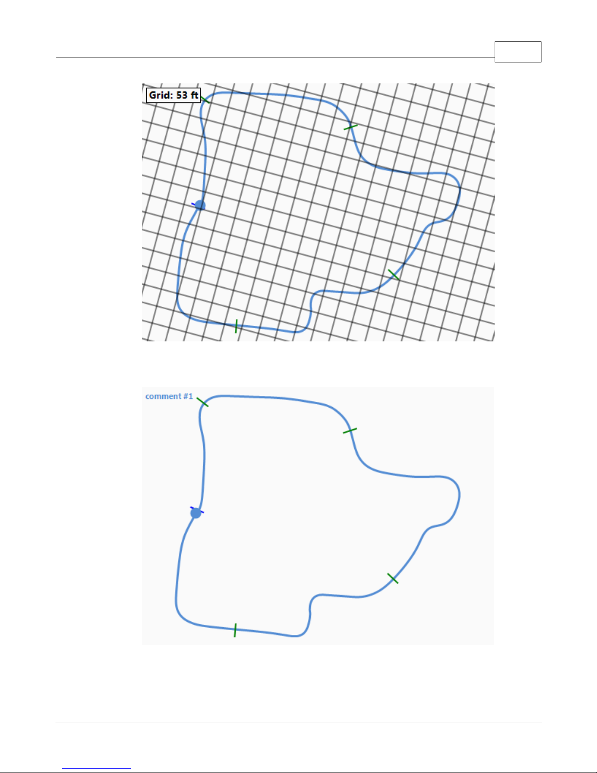
XTStudio 79
Show track map legend
This option will show the keyboard shortcut keys associated with the track map window.
Show track map comments
This option will display the track map comments in the upper left of the track map screen.
© 2009 XT Racing
Page 84
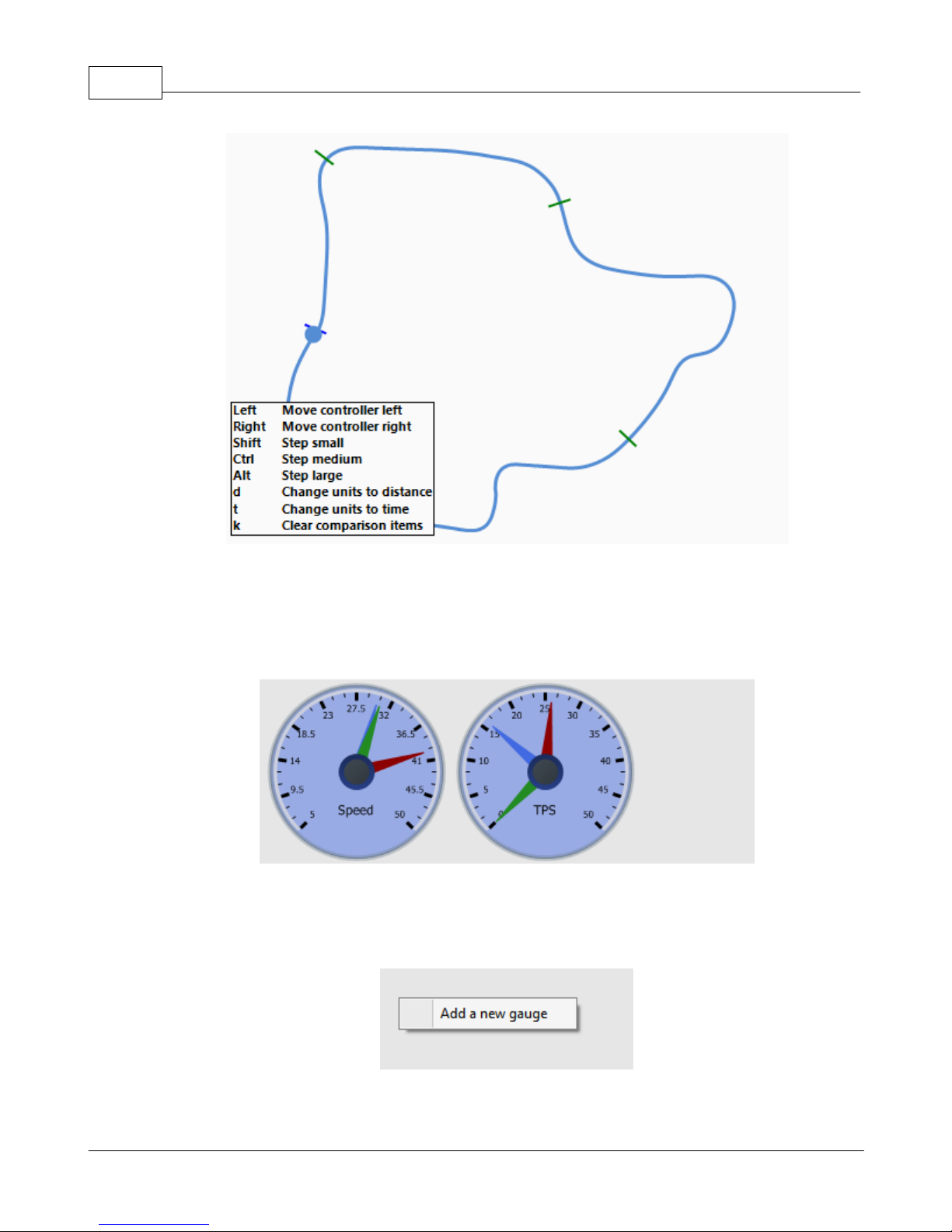
GPX Pro Manual80
2.4.5 Gauge bar
The gauge bar displays a series of circular gauges where the current data values are shown for a
given data channel. Multiple gauge bars can be added to XTStudio and multiple gauges can be
added to a single gauge bar.
Each gauge will have one needle for each comparison item where, again, the color corresponds to
the color in the controller bar. You can add a new gauge to the gauge bar by right-clicking in the
blank area to the right or below the gauges.
To change the input, move the gauge or remove the gauge from the gauge bar, simply right click
© 2009 XT Racing
Page 85
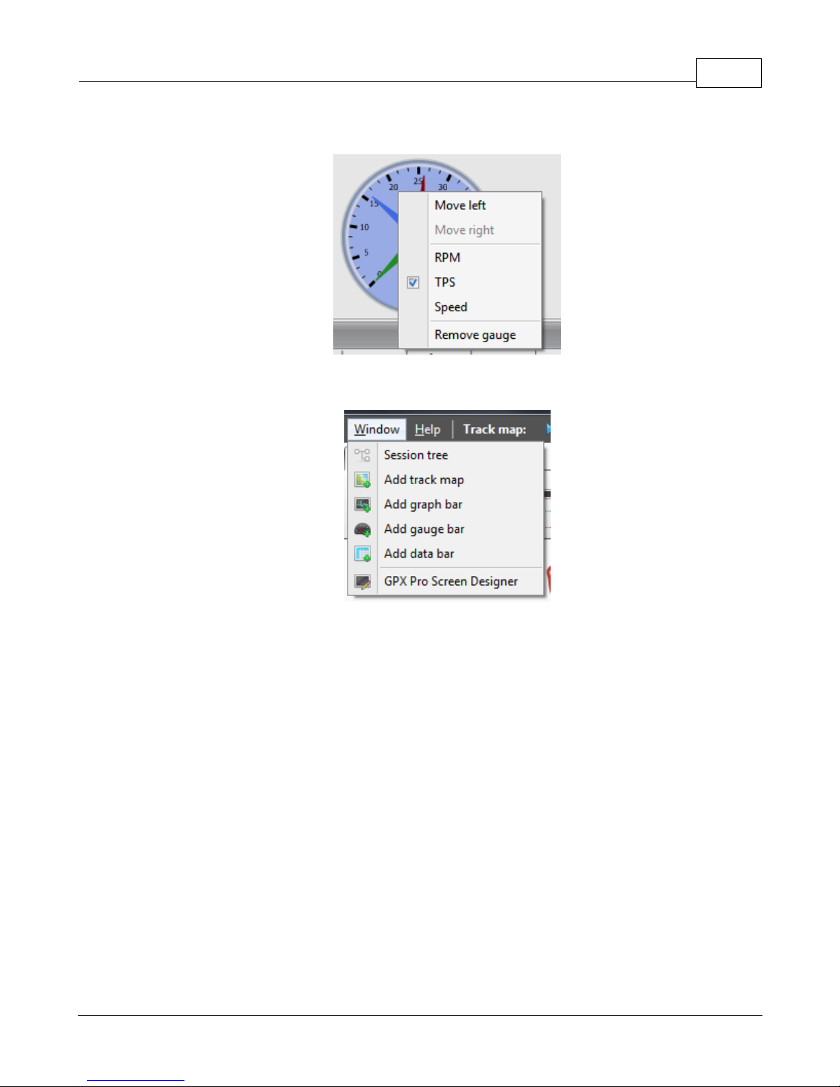
XTStudio 81
on the gauge and choose the option you want.
Gauge bars can be added to the screen through the Window -> Add gauge bar menu.
2.5 Designing screens
With XTStudio, you not only have a powerful lap analysis tool but also a way to customize the GPX
and truly make it your own. Using the screen designer in XTStudio, you can customize any and all
of the GPX screens with your own boxes, lines, data acquisition value... even images! With
custom screens for each racing mode (Circuit, Point-to-Point, Drag, Instrument) and for each
screen type (Main screen, Session summary, Lap details, Spinner), there are literally infinite ways
to make the GPX Pro your own.
2.5.1 Overview
You can access the GPX Pro screen designer by going to Window > GPX Screen Designer.
© 2009 XT Racing
Page 86
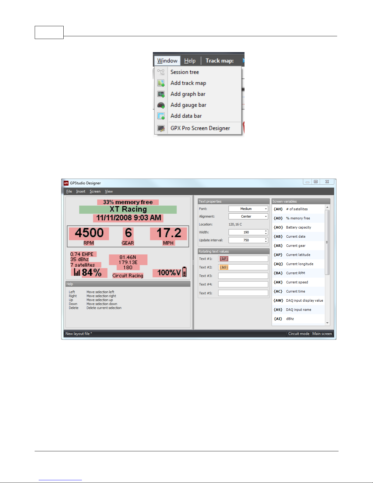
GPX Pro Manual82
Starting the screen designer for the first time will bring up the designer with no layout file
loaded, if you have already started designing screens, then the designer will open the last layout
you were editing.
The designer window is split up into two sections, the screen display on the left and the object
editor on the right. In addition there is a status bar that tells you the current layout file you are
editing (with a star next to it if it has changed) and the active mode and screen you are editing.
In the screen, each object is displayed using a sample text value and a red background that shows
how much space the object takes on the screen. If the object is selected, the background changes
to green and the object editor on the right changes to give the information about that object. In
addition to editing the object's properties, while an object is green, you can use the mouse to
drag the item around the screen or use the arrow keys to nudge it.
© 2009 XT Racing
Page 87
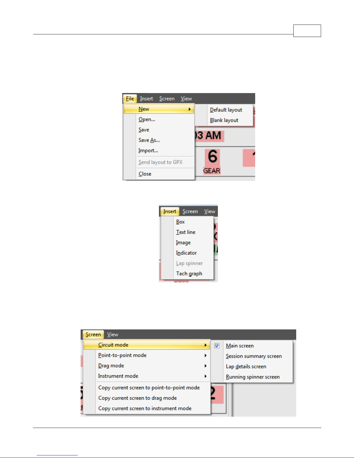
2.5.2 Menus
The file menu allows you to maintain your layout files. The file menu is also where you can send
the opened layout to the GPX Pro (only available if the GPX Pro is currently connected to the
computer) or you import certain screens from a friend's layout file.
The insert menu allows you to add the object types to the current screen layout.
XTStudio 83
The screen menu is used to switch the active mode or screen type. In addition, it allows you to
copy the current screen layout from one mode to another. For example, if you want your pointto-point main screen to be the same as the circuit main screen, then you can choose Copy current
screen to point-to-point mode while the active screen is the circuit mode main screen.
© 2009 XT Racing
Page 88
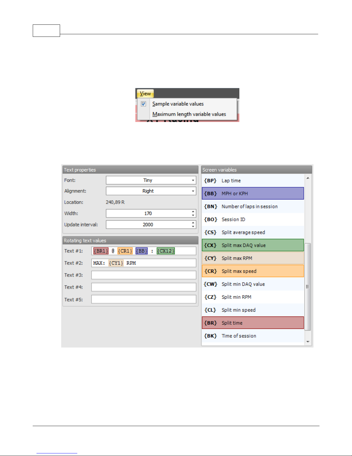
GPX Pro Manual84
The view menu allows you to switch the display value of the screen from the sample values to the
maximum length values. Maximum length value display is used to make sure that your text fields
are wide enough to handle all screen variable values.
2.5.3 Text objects
The GPX Pro text object is the most powerful object for designing screens. The text object allows
you to display all of the data values that are available in the GPX Pro timer.
The text object properties editor is divided into three sections. The text layout properties, the
text display values and the screen variable list.
The text layout properties defines the font, the alignment of the text within the box, the location
of the box, the width of the text box and the update interval of the text fields. The update
interval tells the GPX Pro timer how often to update the screen with this text value, or if there are
multiple rotating text values then how often to switch between the text values. The update
© 2009 XT Racing
Page 89
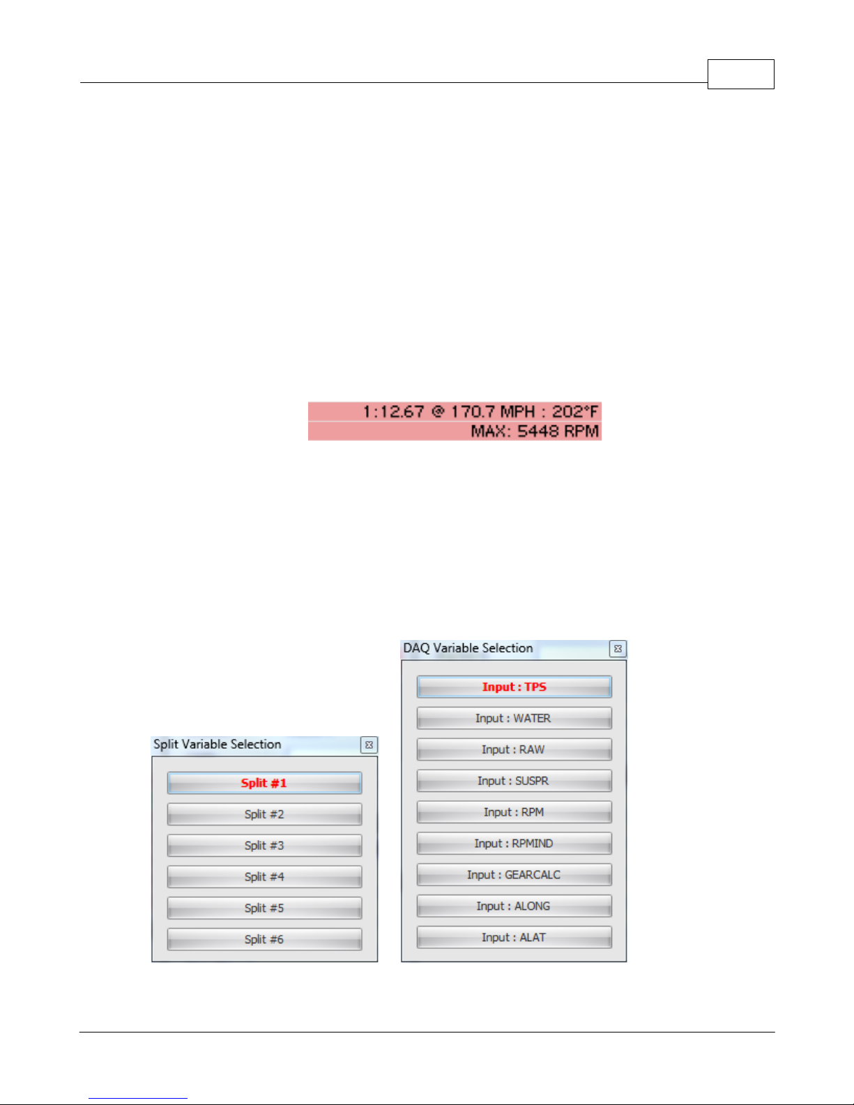
XTStudio 85
interval time is specified in milliseconds so 1000 is 1 second, 2000 is 2 seconds, etc.
The rotating text fields specify the values to display in the text box, again if you specify more than
one text value then the GPX Pro timer will rotate between the values at the specified update
interval. Regular text is entered by just typing in the text you want to display; however, it is the
screen variables that really give the text object its power.
A screen variable is a two letter (and up to two number) combination enclosed in curly brackets.
This special sequence of characters tells the GPX Pro to insert a screen variable value in the place
of the curly bracketed section. The available variables are displayed in the screen variables list.
In addition if you have screen variable sequences in the text boxes, then they will get colored
according to which variable they match up to like in the above screen shot. This will help you see
the link between the text field and the variable.
As an example, the above setup will rotate between the following two values every 2 seconds:
To insert a screen variable from the list, click in the text box where you want to insert the variable
and then double click on the variable from the list, this will insert the curly bracket for you in the
text box. Data acquisition values and split time data values have up to two additional digits in the
curly bracket. These specify the input to display and the split time to display it for. When you
double click on one of these variables, a selector will come up that you can use to specify the DAQ
input or the split number or both. If you want to edit an existing curly bracket with DAQ or split
values, you can double click on the colored box in the text box and the dialog will reappear. Then
you can select a different input or split and designer will update the text variable.
© 2009 XT Racing
Page 90
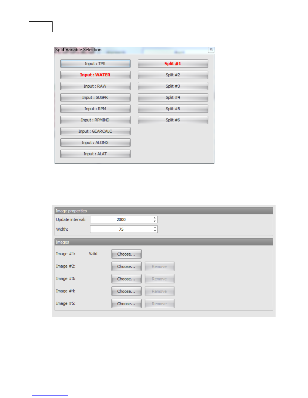
GPX Pro Manual86
2.5.4 Images
The image object is used to insert an image on your screen. Again, the update interval specifies
how fast the image rotates if you specify more than one image.
2.5.5 Indicators
There are two indicators available. The battery graphic and the GPS antenna graphic. Simply
choose which you want to display.
© 2009 XT Racing
Page 91
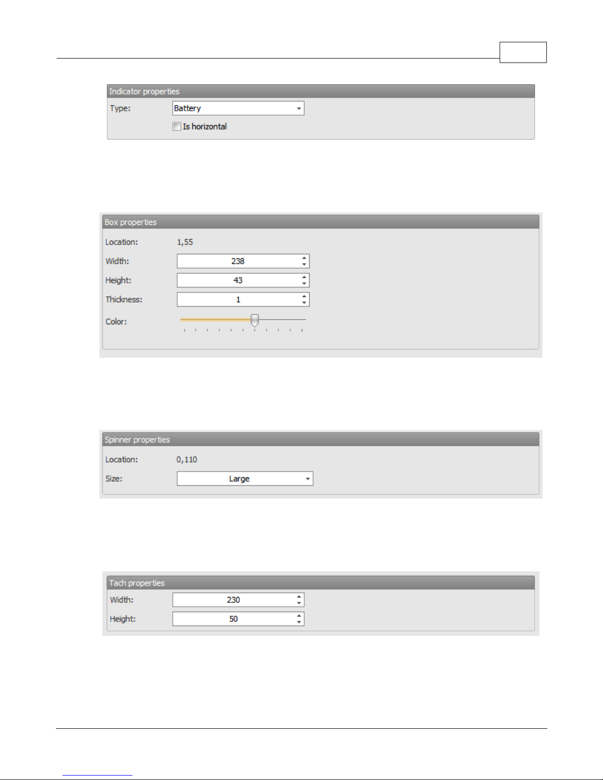
2.5.6 Boxes
The box object is used to draw a box on the screen. You can specify the width, height and
thickness of the box. The bar at the bottom is used to control the line color of the box.
XTStudio 87
2.5.7 Lap spinner
The lap spinner is the displayed current running lap or race time. There are two sizes of spinners
available, large or small.
2.5.8 Tachometer graph
The tachometer graph is used to display the tach graph for your current RPM. You can specify the
width and height of the graph.
2.6 Windows drivers
The Windows drivers are provided on the XTStudio installation CD and they are also copied to C:
\Program Files\XT Racing\XTStudio\Driver after the XTStudio installation is complete. You may
also need your original Windows CD when installing the driver.
© 2009 XT Racing
Page 92
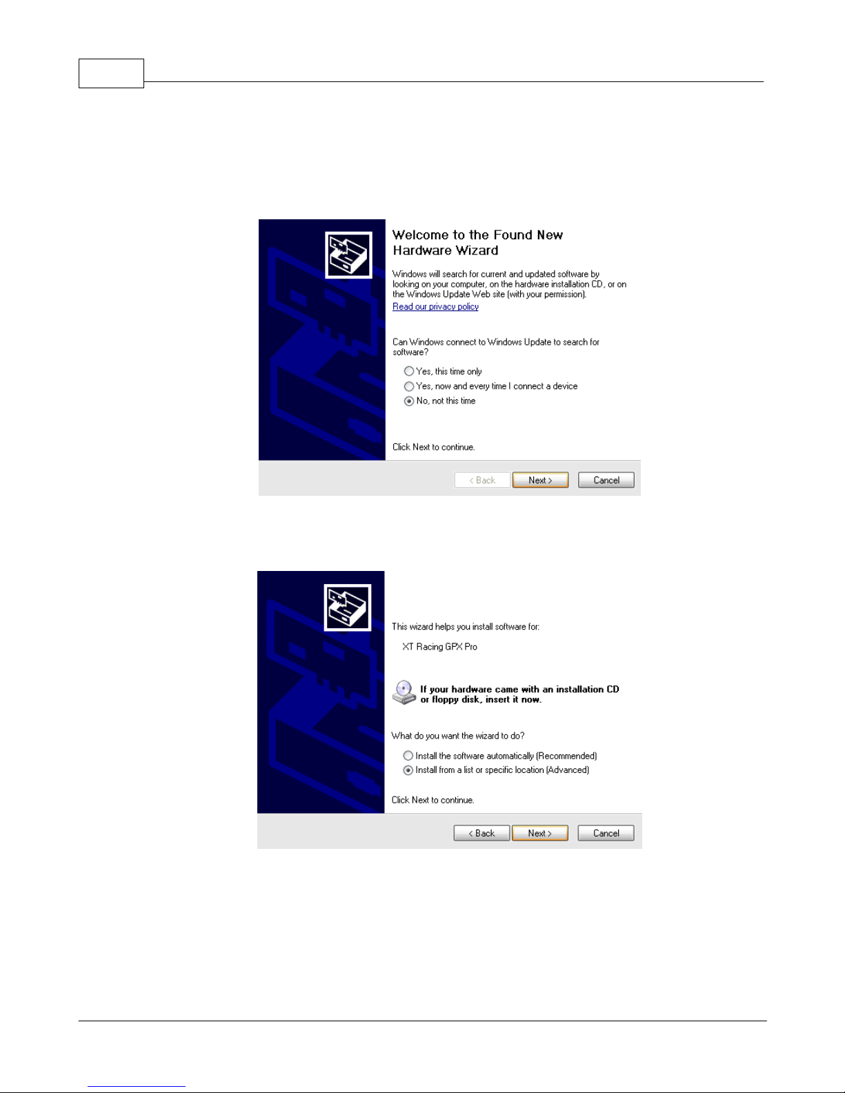
GPX Pro Manual88
Windows XP
To begin the installation of the GPX Pro driver on Windows XP simply plug the GPX Pro into your
computer's USB port. After the device is connected, the Found New Hardware Wizard will appear.
Choose "No, not this time" when the wizard asks you to connect to Windows Update to search for
the driver. Then click Next.
If you have the XTStudio CD inserted, then you can choose "Install software automatically", or if
you have already installed XTStudio (and do not have the XTStudio CD inserted) then you should
choose "Install from a list or specific location". Then click Next.
© 2009 XT Racing
Page 93
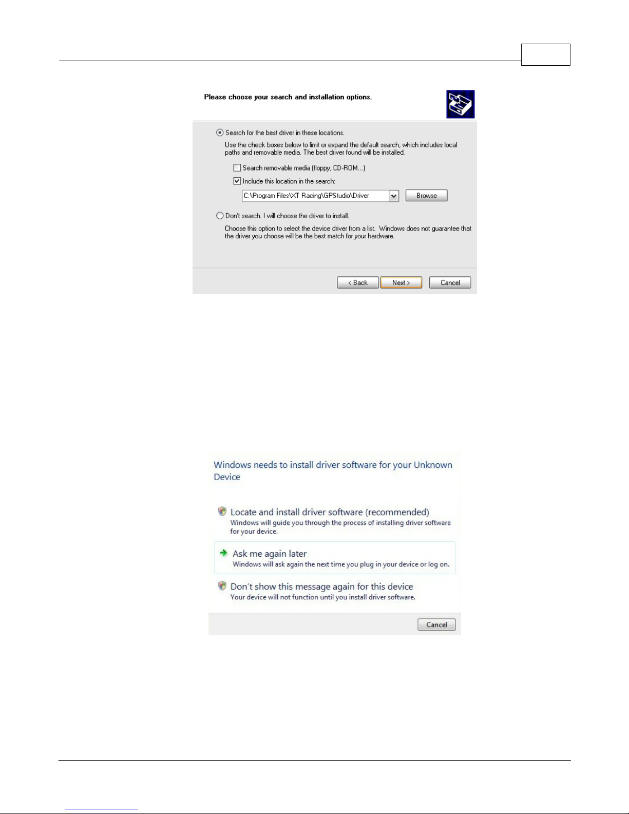
XTStudio 89
In the "Include this location in the search" box enter "C:\Program Files\XT
Racing\XTStudio\Driver". Then click Next. Again, it is possible that you will need to provide the
original Windows CD if prompted. After the driver installation is complete, if XTStudio is running
it will need to be restarted for the communication to proceed.
Windows Vista
To begin the installation of the GPX Pro driver on Windows Vista simply plug the GPX Pro into
your computer's USB port. After the device is connected, the Found New Hardware Wizard will
appear.
On the Found New Hardware Wizard choose "Located and install driver software". If you have the
XTStudio CD inserted then Windows should automatically find and install the driver. If you have
already installed XTStudio and do not have the CD inserted, then Windows will say that it couldn't
find the driver software.
© 2009 XT Racing
Page 94
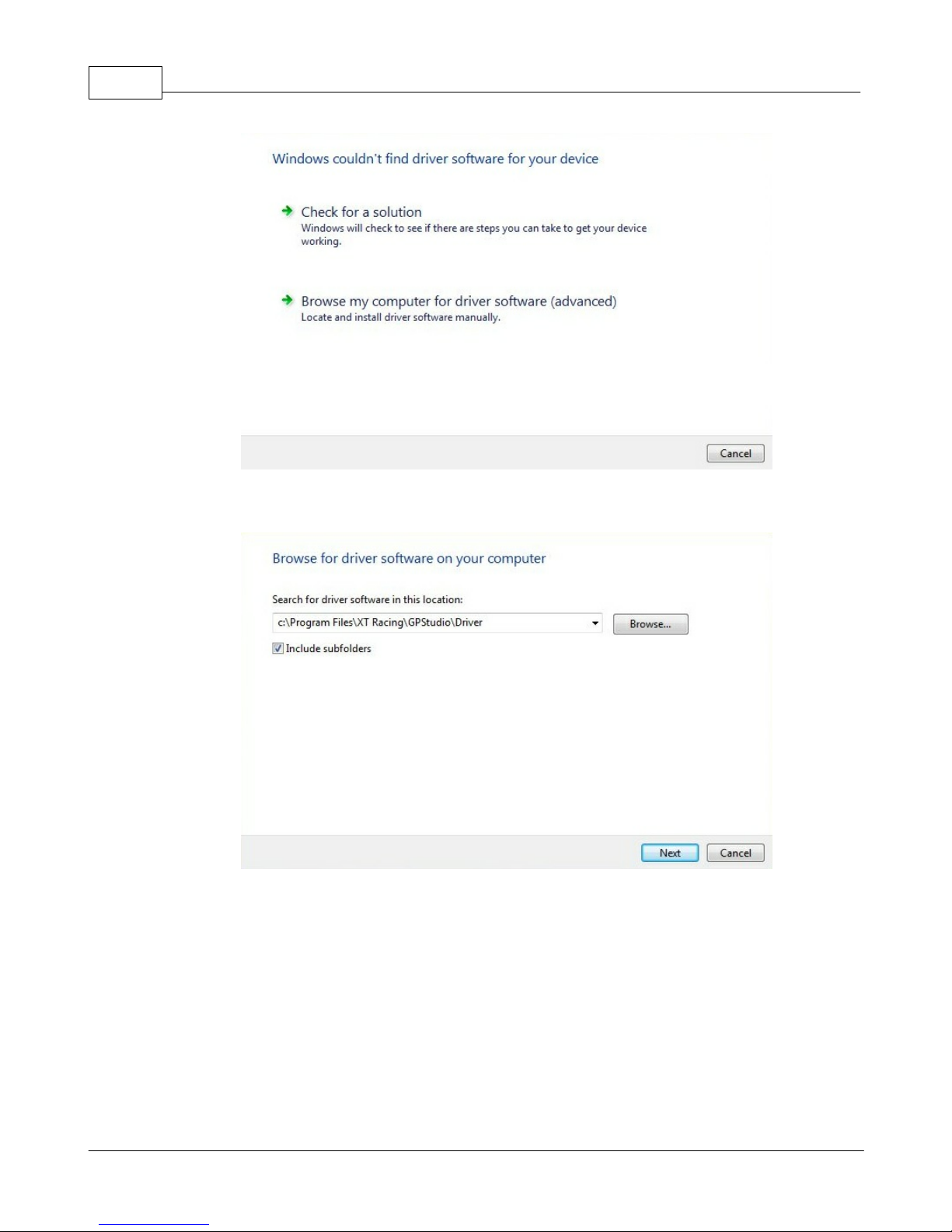
GPX Pro Manual90
If this is the case, then choose "Browse my computer for driver software"
In the "Search for driver software in this location" box enter "C:\Program Files\XT
Racing\XTStudio\Driver". Then click Next. This will install the GPX Pro driver.
© 2009 XT Racing
Page 95
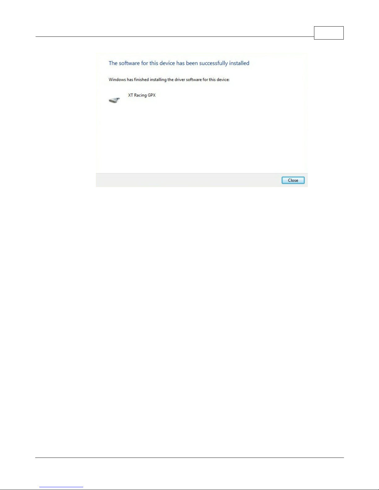
XTStudio 91
© 2009 XT Racing
 Loading...