

Page 1
ASSEMBLY MANUAL
Features of Your New XTM Racing X-Cellerator Racer:
●
Factory-Assembled Chassis and Drive-Train
●
Stylish Black & Blue-Streak Anodized 3mm Aluminum Chassis
●
Custom Receiver On/Off Switch w/Charge Cord
●
Aluminum Tuned Pipe
●
Engine Header w/Gasket and Coupler
●
Complete Clutch Assembly & Engine Mounts
●
Servo Mounts, Linkages, Hardware & Chassis Brace
●
Dual-Sponge Air Filter
●
Complete Ball-Bearing Set
●
Fuel Line
Thank you for purchasing the XTM Racing X-Cellerator Racer. This Assembly Manual is provided to help you enjoy your new X-Cellerator
Racer without any of the hassles you might expect. Please read through all of the literature that is provided in the box.
✦✦
✦IMPORTANT
✦✦
✦✦
✦ Before operating your new X-Cellerator Racer, please read and understand the warnings listed on the next page. Failure to do so
✦✦
could lead to bodily harm and/or injury. The XTM Racing X-Cellerator Racer is not intended for persons under 12 years of age, unless closely
supervised by an adult.
●
Clear Body w/Rear Spoiler, Body Clips & Decal Sheet
●
Front and Rear Sway Bars
●
46T & 47T Spur Gears (46T Installed)
●
15T, 16T & 17T Clutch Bells
●
1º, 2º & 4º Rear Suspension Mounts (1º Installed)
●
Dish Wheels
●
Shock Dust Boots
●
Threaded Shock Bodies
●
Center-Mounted Fuel Tank
●
CVA-Type Rear Drive Axles & Much, Much More
The XTM Racing X-Cellerator Racer is distributed exclusively by Global Hobby Distributors
All contents copyright © 2003, Global Hobby Distributors Version V1.0 November 2003
Need help or have any questions? Call us at 1-714-963-0329 or send us an Email at service@globalhobby.net
18480 Bandilier Circle, Fountain Valley, CA 92708
Kit Product # 145611
1
Page 2
FOR YOUR SAFETY - PLEASE READ THESE WARNINGS FIRST!
ENGINE WARNINGS
●
Never use any fuel in your engine other than glow fuels
specifically designed for use in model car engines. Use of any
other types of fuel can cause severe damage to the engine and/or
personal injury. NEVER USE GASOLINE!
●
Never operate your model on any public streets. This could
cause traffic accidents, personal injury or property damage.
●
Glow fuel engines emit exhaust vapors that are poisonous and
can be dangerous to your health. It is important that you operate
your engine in a very well-ventilated area, preferably outdoors.
●
Before starting the engine, make sure that the throttle trim is
set to the idle position. Starting the engine at any setting above
idle can cause the model to lurch out of your hands.
●
When the engine is running, there are certain parts that rotate
at high speeds. Be careful not to touch the drive shafts, gears,
clutch assembly or any other moving parts. Otherwise, serious
injury could result.
●
It is normal for the engine, exhaust header and tuned pipe to
get very hot during operation. Never touch these parts while
they are hot or you might be burned.
●
Model car engines produce vibration when they are running. It
is important to periodically check the engine mounting screws
and other assemblies to ensure they are tight. Running the
engine with the engine mounting screws loose can lead to
severe engine and/or chassis damage.
FUEL WARNINGS
●
Glow fuels like those used in your X-Cellerator Racer are
poisonous. Follow all the precautions that are printed on the fuel
manufacturer's container.
●
Keep fuel out of the reach of children.
●
Glow fuel is extremely flammable. Keep away from high heat,
sparks and flame.
GENERAL WARNINGS
●
Under no circumstances should you operate your model in
crowds of people. Serious injury could result.
●
Never operate your model on busy streets or if there are cars
around.
●
Do not use your model to chase pets or other animals.
●
The receiver and battery boxes are not waterproof; therefore,
do not drive through water, wet grass, mud or snow.
●
Because your model is operated by radio control, it is important
to make sure you always are using fresh and/or fully charged
batteries. Never allow the batteries to run low or you could lose
control of the model.
●
If your model becomes stuck, allow the engine to idle, then
retrieve your model by hand.
●
To prevent excessive r.p.m.'s from damaging the engine and/or
drive-train components, we suggest reducing throttle while in the
air during jumps.
FOR YOUR INFORMATION
If you should have any trouble with any of the steps listed in this Assembly Manual, we have provided an extensive troubleshooting guide
beginning on page # 16. The troubleshooting guide is provided to help you find a quick and immediate resolution to a number of
problems that might occur. If you cannot solve a problem using the troubleshooting guide, or if you have any other questions or
concerns, please contact us at the address below:
Global Services
18480 Bandilier Circle
http://globalservices.globalhobby.com
Fountain Valley CA 92708
Phone: (714) 963-0329 Fax: (714) 964-6236 Email: [email protected]
CHECK IT OUT! We urge you to come check out our website at http://globalservices.globalhobby.com. There you will find public message boards
frequented by other XTM Racing product owners and the XTM Racing support staff. This is a great place to learn about new XTM Racing products,
get help and suggestions for your current XTM Racing products or just simply hang out and chat with people that share your same interests.
To allow us to serve your needs better, please include your email address with any correspondence you send to us. Your email address will be added to our Customer
Service Database so you will automatically receive free updates and tech notices for your particular product. You will also receive repair status updates (if applicable) and
other important information about your product as it becomes available.
IMPORTANT INFORMATION ABOUT YOUR EMAIL ADDRESS
Global Hobby Distributors will not disclose the information it collects to outside parties. Global Hobby Distributors does not sell, trade, or rent
your personal information to others . Your privacy is important to us.
Visit Our Website
2
Visit our website at http://xtm.globalhobby.com or for Customer Service at http://globalservices.globalhobby.com
Page 3

INTRODUCTION
Have it your way with the new X-Cellerator Racer from XTM. This 1/10 Scale Nitro Stadium Truck is a factory-assembled chassis,
complete with many hop-ups and suspension and gearing options normally only found as aftermarket items - all included in the box!
XTM gives you everything serious racers want and none of the things they don't. We've included everything we could for you to
customize your X-Cellerator Racer to your favorite track's conditions and we've done all the tedious work for you. You'll find inside a
great factory-assembled chassis, suspension, shocks, differential, transmission and linkage. We've even included our unique radio
switch with custom-routed wire and charge-plug, so there's no need to remove the receiver battery for charging.
The included body is clear because we know you'll want to race with your own "team" colors. We've also included great all-around racing
tires and inserts from the leader in racing tires, Proline. These proven Proline M2 compound tires are great for most track surfaces, so
right from the box you'll be using quality race tires.
What's not in the box? No radio control system or engine is included. If you're a hardcore racer, you'll want to use your own favorite radio
control system and your own favorite .12 or .18 size rear-exhaust racing engine, according to your racing program's rules. So, forget
about the rest, you have the best. Go from the box to the Winner's Circle in only hours, with the X-Cellerator Racer from XTM.
SECTION 1: PARTS IDENTIFICATION
Before beginning assembly, remove the main parts and the separate parts bags from the box and use the parts list below to verify that
your kit contains all of the correct parts bags and main parts. If your kit is missing a parts bag, a main part or even a singe part, please
contact us immediately, using the contact information listed on the bottom of page # 2.
1 - Assembled Chassis w/Battery Box and Switch
2 - Front Wheels & Tires
2 - Rear Wheels & Tires
1 - Aluminum Tuned Pipe Bag
1 - Exhaust Header Bag
1 - Engine Air Filter Bag
1 - Air Filter Prefilter Bag
1 - 47T Spur Gear Bag
1 - 15T Clutch Bell Bag
1 - 17T Clutch Bell Bag
1 - Clutch Assembly Bag w/16T Clutch Bell
1 - Rear Sway Bar Assembly Bag
1 - Throttle Servo Bag
1 - Steering Servo Bag
1 - Wheel Mounting Bag
1 - Engine Mounts Bag
1 - Throttle and Brake Linkage Bag
1 - Antenna Tube
1 - Fuel Line Bag
1 - Molded Tools Bag
1 - Clear Polycarbonate Body w/Wing
1 - Decal Sheet
1 - Front Sway Bar Assembly Bag
The different parts bags contain a number of small parts that are identified throughout this assembly manual. We don't suggest
opening the parts bags until you actually need them. This will prevent you from loosing any of the small parts. It will also make it easier
for you to identify the parts.
SECTION 2: RECOMMENDED ITEMS AND TOOLS NEEDED
This section lists the recommended items you need to purchase and have on-hand to finish assembling and to run and maintain your
new XTM X-Cellerator Racer.
●
Radio Control System w/2 Servos with 50oz/in or More Torque at 6 Volts
●
.12 - .18 Size Rear-Exhaust Engine w/Regular Shaft
●
XTM Racing 5 Cell 1000Mah NiCD Receiver Battery Pack (P/N 145801)
●
XTM Racing Mega-Stick Tire Glue (P/N 145900)
●
Trinity "Final Solution" After-Run Oil (P/N 843744)
●
XTM Racing Air Filter Oil (P/N 149571)
●
Associated Thread-Lock Adhesive (P/N 588996)
●
Assorted Sizes of Hex Wrenches
●
Needle Nose Pliers, Adjustable Wrench, Flat & Phillips Head Screwdrivers
Need help or have any questions? Call us at 1-714-963-0329 or send us an Email at [email protected]
●
Fuel to Suit Your Engine
●
Glow Plug to Suit Your Engine
●
XTM Racing 500cc Fueling Bottle (P/N 145920)
●
XTM Racing 4-Way Wrench (P/N 149178)
●
XTM Racing Glow Starter w/Meter & Charger (P/N 146045)
●
XTM Racing Curved Lexan Scissors (P/N 145945)
●
XTM Racing Body Reamer (P/N 146085)
●
Assorted Paint and Material to Finish the Body
3
Page 4
SECTION 3: ASSEMBLING YOUR X-CELLERATOR RACER
Your X-Cellerator Racer includes three different clutch bells and two different spur gears so you can have control over the final drive ratio
of the truck. This will allow you to suit the truck to your driving style and track conditions. Listed below are the gear ratios that are
available, using the different combinations of clutch bells and spur gears:
15T Clutch Bell & 46T Spur Gear = 3.06:1
16T Clutch Bell & 46T Spur Gear = 2.87:1
17T Clutch Bell & 46T Spur Gear = 2.70:1
15T Clutch Bell & 47T Spur Gear = 3.13:1
16T Clutch Bell & 47T Spur Gear = 2.94:1
17T Clutch Bell & 47T Spur Gear = 2.76:1
The 46T spur gear has already
been installed on the truck.
Basically, using the smallest clutch bell with the largest spur gear will give the truck great low-end acceleration, but top speed will be
sacrificed. Using the largest clutch bell with the smallest spur gear will give the truck enormous top speed, but low-end acceleration will
be sacrificed. So, if your track is very tight with a lot of corners, you would probably want to use a combination that will give you good
low-end acceleration versus a high top speed. If your track has a lot of straightaways, you would probably want to use a combination that
gives you higher top speeds.
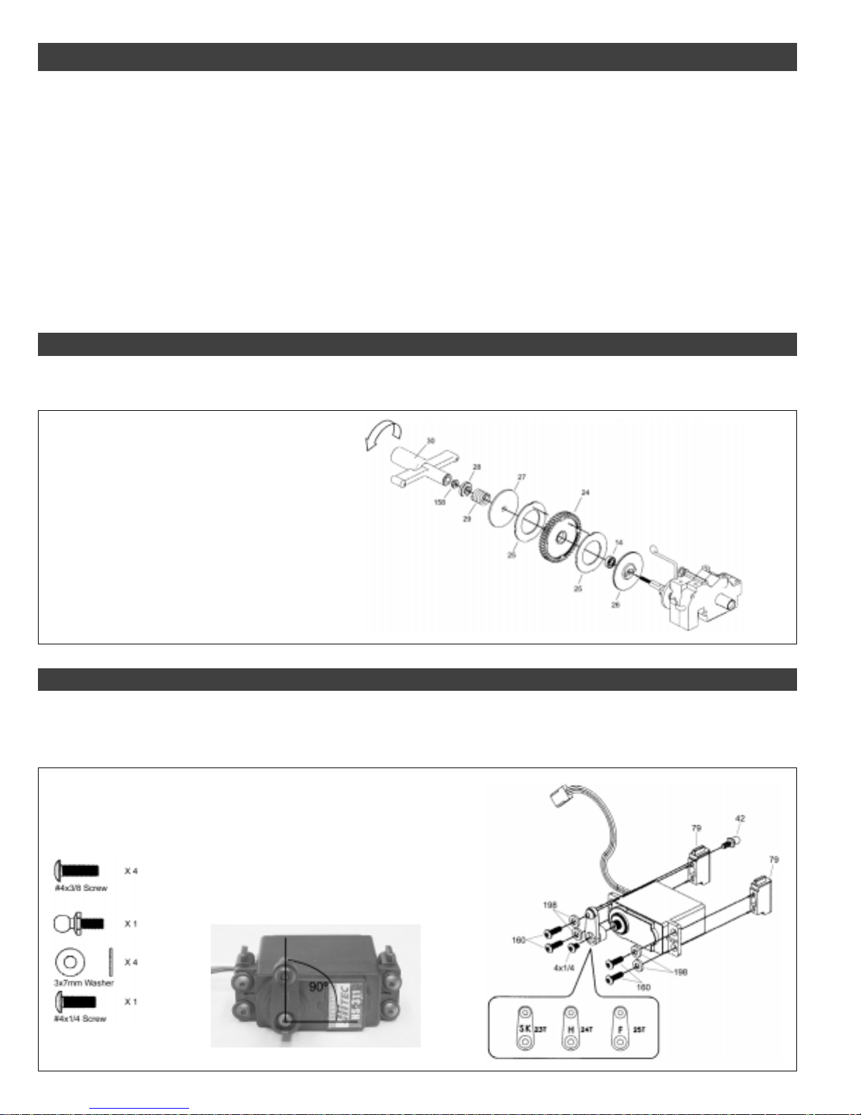
Step 1: Changing the Spur Gear
●
The 46T spur gear has been preinstalled from the factory. If you want to change the spur gear to the 47T option, do that now, following
the diagram below:
Drawing # Part # Part Description
14 149148 Ball Bearings (3/16" x 3/8")
24 149089 47T Spur Gear
25 149086 Slipper Pads
26,27 149090 Slipper Discs
28,29 149087 Slipper Spring & Washer
158 149163 Lock Nut Set
30 149141 Tool Bag
When removing the slipper pads from
the original spur gear, be careful not to
damage them. We recommend using a
small flat blade screwdriver to pry them
off of the spur gear.
When reassembling the slipper clutch,
tighten the hex nut completely then
back it off 5 turns. This is a good
starting point until you can make final
adjustments while driving the truck.
Step 2: Steering Servo Assembly
●
Install your steering servo onto the steering servo mounts.
●
Install the servo arm onto your servo, making sure that it's centered, as shown in the photo. You'll need to connect your radio control
system and turn it on to center the servo. Make sure that the steering trim lever on your transmitter is centered.
Drawing # Part # Part Description
160 149171 Screw Set
198 149179 Nylon Washers
42 149161 Bell Studs
Three different servo arms are included.
They are labeled for use with "H" for Hitec,
"F" for Futaba and "S" for Sanwa. Make
sure that you use the correct servo arm for
the particular brand of servo you're using.
Note that the ball-end is
mounted on the back of the
servo arm.
4
Visit our website at http://xtm.globalhobby.com or for Customer Service at http://globalservices.globalhobby.com
Page 5
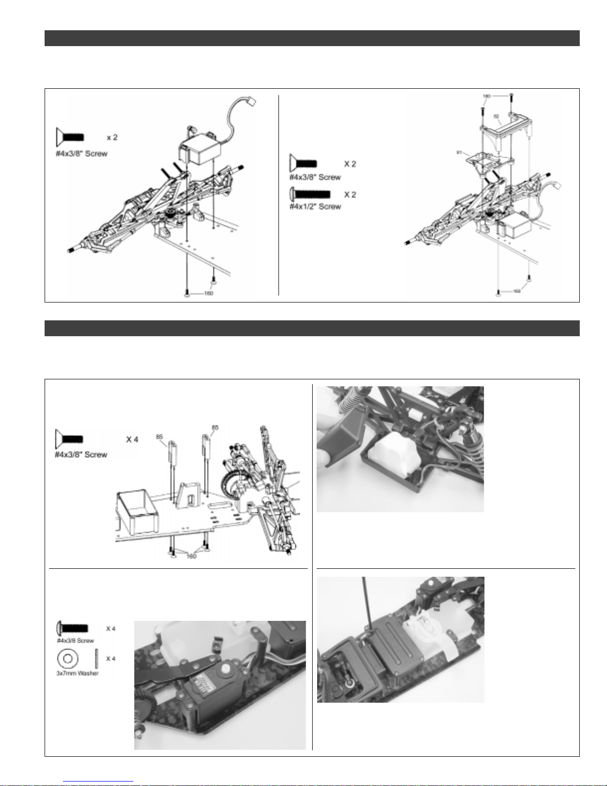
Step 3: Mounting the Steering Servo Assembly
●
Install the steering servo assembly to the chassis, then carefully snap the ball-end on the steering arm to the bell stud on the servo arm.
●
Install the steering brace to the chassis to complete the installation.
Drawing # Part # Part Description
160 149171 Screw Set
Drawing # Part # Part Description
160 149171 Screw Set
81 149133 Ft. Bulkhead & Brace
82 149134 Steering Brace
Note that the front brace (81) has already
been preinstalled on the chassis for you.
Step 4: Mounting the Throttle/Brake Servo Assembly and Installing the Battery and Receiver
●
Install the throttle/brake servo mounts to the chassis, then install your throttle/brake servo to the servo mounts.
●
Install your receiver battery into the battery box, then install your receiver into the receiver box.
Drawing # Part # Part Description
160 149171 Screw Set
85 149139 Throttle Servo Mounts
The U-Shaped
cutouts in the
servo mounts
go toward the
chassis.
Drawing # Part # Part Description
160 149171 Screw Set
198 149179 Nylon Washers
Note that the
servo output
shaft is toward
the front of the
chassis.
Note that if you don't use
a rechargeable battery
pack, you will need to
install 4 AA cells in the
battery box.
The extra lead tied to the
chassis is a charge lead
for rechargeable batteries
only. Do not attempt to
recharge Alkaline cells.
The battery box cover has been preinstalled.
You'll need to remove it first before installing the
battery. When reinstalling the battery box cover,
be careful not to pinch the battery wire.
Slide the antenna into
one end of the plastic
antenna tube and out the
other end, then push the
end of the antenna tube
into the molded hole in
the top of the receiver
box cover.
The receiver box cover has been preinstalled. You'll need to remove it
first before installing the receiver. When reinstalling the receiver box cover,
be careful not to pinch the wires. When installing the receiver box cover,
make sure to run the receiver antenna out the hole in the top of the cover.
Need help or have any questions? Call us at 1-714-963-0329 or send us an Email at [email protected]
5
Page 6
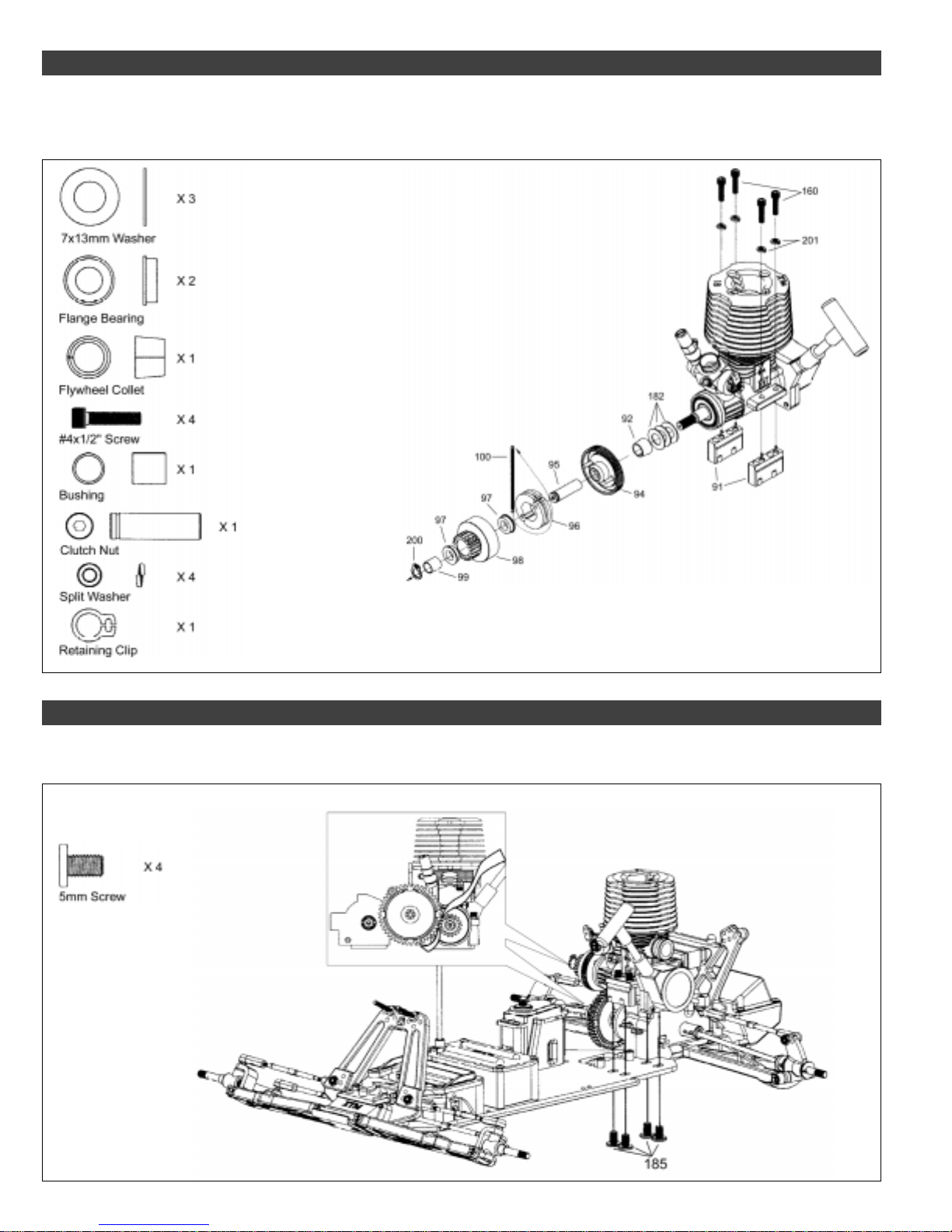
Step 5: Installing the Clutch Assembly
●
Install the flywheel, clutch shoes and clutch bell assembly onto your engine, keeping in mind that you have the choice of using a 15T,
16T or 17T clutch bell.
●
Install the engine mounts onto your engine, paying close attention to the orientation of the engine mounts, as shown in the drawing.
Drawing # Part # Part Description
160 149171 Screw Set
92 148334 Collet for Flywheel
94 149069 Flywheel w/Clutch Posts
182 149068 Steel Washers
95 149074 Clutch Nut
96 149066 Clutch Shoes
97 149147 Flanged Ball Bearings
99 149073 Clutch Nut Bushing & Clip
100 149067 Clutch Spring
201 149162 Split Washers
Tighten the clutch nut firmly,
using a pair of pliers, before
installing the bushing and
retaining clip.
We strongly suggest applying Thread-
Lock to the engine mounting screws to
prevent them from loosening during use.
Before installing the clutch bell, lightly sand the inside surface of the
clutch bell, using 600 grit sandpaper , then clean it thoroughly, using
rubbing alcohol. Doing this will allow the clutch shoes to "bite" better,
reducing clutch slipping.
Step 6: Installing the Engine
●
Install your engine to the chassis, taking care to ensure that the engine is lined up properly and that the gear mesh between the clutch
bell and the spur gear is correct. It's important that the gears do not bind.
Drawing # Part # Part Description
183 1149176 Engine Mount Screws
We strongly suggest applying Thread-
Lock to the engine mounting screws to
prevent them from loosening during use.
To set the gear mesh, place a piece of notebook paper
between the two gears. When set properly, there should be
a very slight play between the gears. If the gears are too
tight they will bind and if they are too loose they will strip out.
6
Visit our website at http://xtm.globalhobby.com or for Customer Service at http://globalservices.globalhobby.com
Page 7
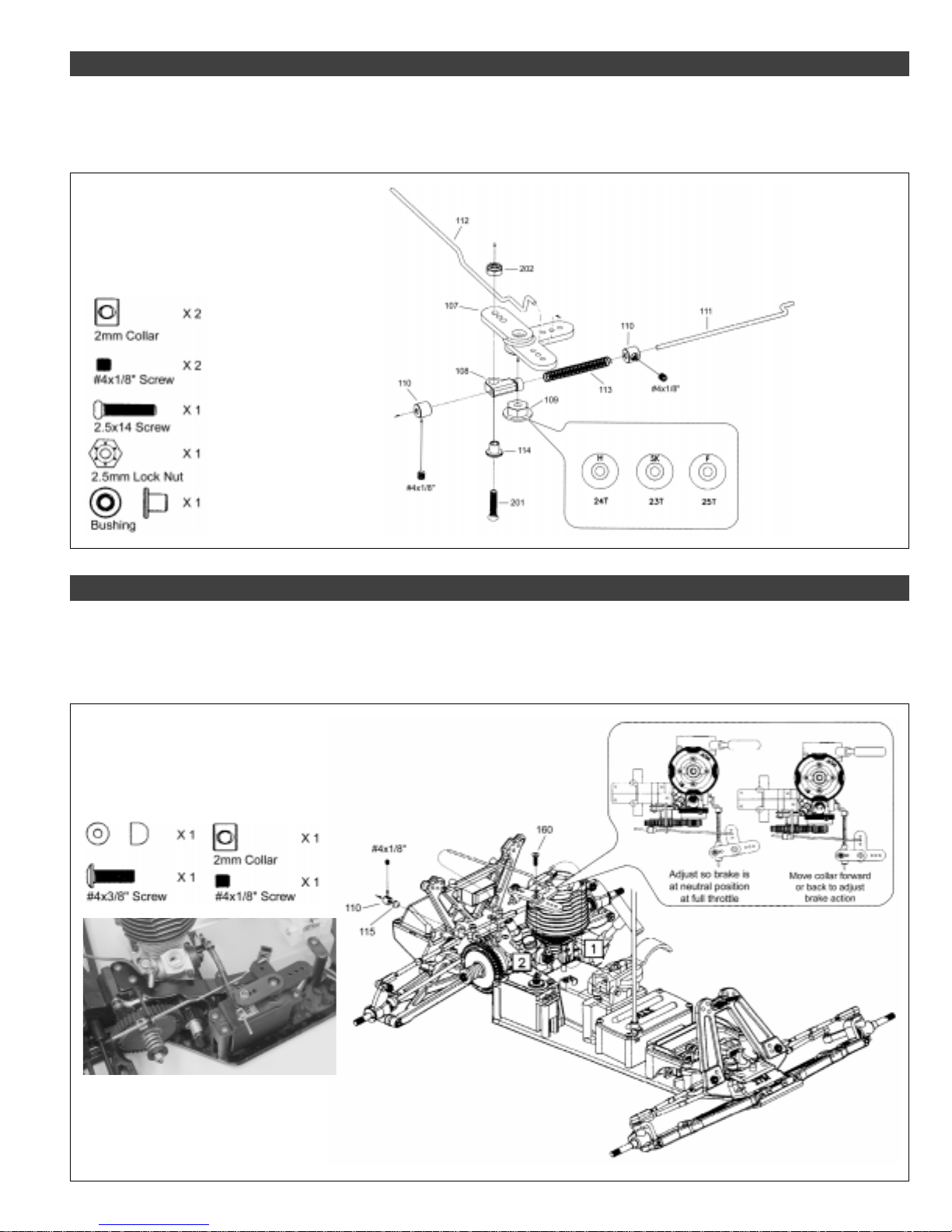
Step 7: Throttle and Brake Linkage Assembly
●
Assemble the throttle and brake linkage, paying careful attention to how the linkage wires are orientated.
●
The linkage assembly is designed to be used with engines that feature a rotary carburetor. If your engine features a slide carburetor,
you will need to modify the linkage accordingly.
Drawing # Part # Part Description
107-109 149145 Throttle Arm Set
149093 #4x1/8" Grub Screws
110-114 149094 Throttle Linkage
201-202 149094 Throttle Linkage
Three different servo arm adapters are included.
They are labeled for use with "H" for Hitec, "F"
for Futaba and "S" for Sanwa. Make sure that
you use the correct servo arm adapter for the
particular brand of servo you're using.
Step 8: Throttle and Brake Linkage Assembly Installation
●
Install the two linkage wires onto your engine's throttle arm and through the brake lever, then install the servo arm onto the servo,
making sure it's centered, as shown in the photo. You'll need to connect your radio control system and turn it on to center the servo.
Make sure that the throttle trim lever on your transmitter is centered.
●
We suggest making the final adjustments to the throttle and brake linkage after you have completed assembly of the truck.
Drawing # Part # Part Description
110 149094 Throttle Linkage
160 149171 Screw Set
115 149145 Throttle Arm Set
149093 #4x1/8" Grub Screws
With the transmitter and receiver turned on, and the throttle/brake trim lever
centered, the spur gear should turn easily (i.e., the brake should be disengaged).
If the brake is dragging when the throttle trigger is at neutral, the brake disc will
wear out very quickly. To ensure that the brake is disengaged, always make sure
that there is a 1/8" gap between the linkage collar (110) and the brake lever.
Need help or have any questions? Call us at 1-714-963-0329 or send us an Email at [email protected]
7
Page 8
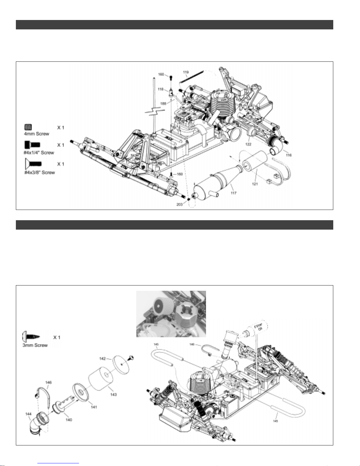
Step 9: Header and Tuned Pipe Installation
●
Install the tuned pipe mount (118) to the chassis.
●
Install the header onto your engine, using the exhaust hanger spring to hold it in place, then install the tuned pipe onto the header and
secure it to the tuned pipe mount. Don't forget to use the two nylon cable ties to secure the exhaust coupler into place.
Drawing # Part # Part Description
116, 119 149076 Exhaust Header
117, 203 149175 Tuned Pipe
118 149082 Tuned Pipe Mount
188 149081 Exhaust Hanger Spring
121 149077 Exhaust Coupler
160 149171 Screw Set
The exhaust header fits
most .12-.18 size
round-port, rear exhaust
engines. If you're using
a side exhaust engine,
after-market headers are
available.
The exhaust hanger spring connects
to the exhaust header and wraps
around the engine to hold the exhaust
header in place.
Step 10: Air Filter and Fuel Line Installation
●
Assemble the air filter, making sure to wet the filter element, using filter oil, so that small dust and debris cannot enter your engine
when it's running.
●
Install the air filter onto your engine, using the larger cable tie to secure it to the carburetor, then cut and install the prefilter element.
●
Install the fuel line. The shorter piece of fuel line connects from your engine's carburetor to the top of the fuel tank, and the longer
piece of fuel line connects from the tuned pipe to the fuel tank lid. The excess fuel line should be clipped into the nylon holder on the top
of the fuel tank.
Drawing # Part # Part Description
140-142 149078 Air Filter Plastic Parts
143 149080 Filter Element
144, 146 149079 Air Filter Elbow
145 149150 Fuel Line
Use the smaller cable tie for
this assembly.
8
Visit our website at http://xtm.globalhobby.com or for Customer Service at http://globalservices.globalhobby.com
Remove the outer sleeve from one of the pieces
of gray foam, cut it in half horizontally, then slide it
over the filter assembly, as shown. This is the
prefilter. Do not oil it like you did the white filter.
It's very important to
oil the white filter
element to trap
small dust and debris.
Page 9
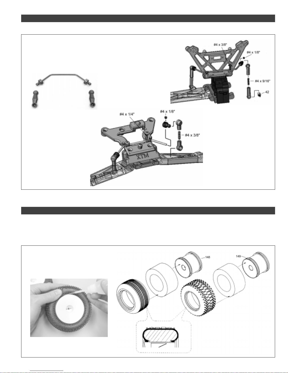
Step 11: Installing the Front and Rear Sway Bars
●
Install the front and rear sway bar assemblies. Note the longer sway bar is mounted in the rear of the chassis.
Drawing # Part # Part Description
149172 Front Sway Bar
149173 Rear Sway Bar
42 149173 Rear Sway Bar
The ball ends should be threaded onto
the threaded shafts so that they are
touching each other. This will result in
the proper length. Do this for both the
front and the rear.
We suggest using Thread Lock to secure
the #4 x 1/8" grub screws into place.
You must thread the ball studs into the
back of the suspension arm for the rear
sway bar assembly. Note that the sway
bar is mounted into the grooves in front
of the rear shock tower and is held
securely by the two threaded screws.
The sway bar is mounted into the
grooves behind the front shock tower
and is held securely by the two
threaded screws. The lower ball ends
mount to the molded ball stud in the
front suspension arms.
Step 12: Mounting the Tires
●
Carefully install the foam inserts into the front and rear tires, making sure that they lay flat within the tire. It's important that they don't
kink or cause the tire to bulge.
●
Carefully install the tires onto the wheels, making sure to install the front tires on the front wheels and the rear tires on the rear wheels.
You must glue the tires to the wheels, as shown below. Do not drive the truck without first gluing the tires to the wheels.
Drawing # Part # Part Description
148 149035 Front Wheel (2)
149 149040 Rear Wheel (2)
The rear wheels have a
molded slot in them to accept
the steel axle pin. The front
wheels don't have this slot.
After mounting the tire onto the wheel, carefully
glue the tire to the wheel, using a good quality
tire glue.
Make sure that the tire bead fits firmly into
the molded groove in the wheel.
Need help or have any questions? Call us at 1-714-963-0329 or send us an Email at [email protected]
9
Page 10
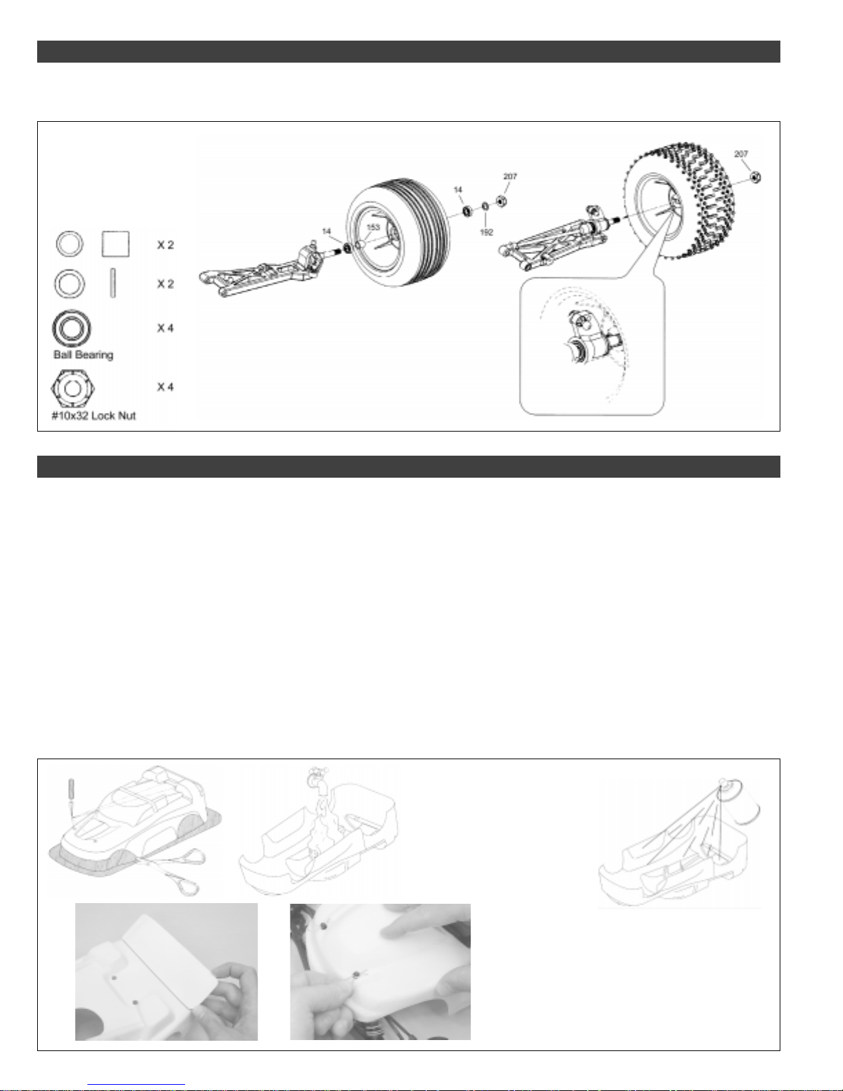
Step 13: Installing the Front and Rear Wheels
●
Install the rear wheels, making sure that the molded slot in the back of the wheel fits over the steel pin on the axle.
●
Install the front wheels, wheel bearing and spacers, making sure to tighten the hex nuts firmly.
Drawing # Part # Part Description
14 149148 Ball Bearings 3/16" x 3/8"
153 149115 Front Bearing Spacer
192 149098 4.8 x 6mm Washer
207 149163 Lock Nut Set
After installing the wheels, double-check that
they spin freely.
Step 14: Mounting the Body
●
Carefully cut out the body along the molded scribe lines, using a pair of Lexan scissors.
●
Using a body reamer, cut out the holes in the top of the body for the four body posts and the antenna to exit. These locations are
marked by molded dimples in the top of the body.
●
Carefully cut out the tuned pipe clearance hole on the left side of the body, the engine cooling and pull-start access hole in the front
windshield, the glow plug access hole in the top of the body and the switch access hole in the back of the body. Again, follow the molded
scribe lines when making these cutouts.
●
Wash the inside of the body with warm water and non-abrasive liquid detergent to remove any chemicals left from the molding
process, then completely dry the body, using a soft cloth. After drying with a soft cloth, allow the body to air dry for a while.
●
Paint the inside of the body, using your favorite materials and methods. Do not paint the outside of the body.
●
After the paint dries completely, peel back and remove the protective plastic material from the outside of the body, then apply the
decals that are included.
●
Secure the wing to the back of the body, using the two sheet-metal screws provided.
●
Secure the body in place, using four metal body clips.
The body comes with a thin, self-adhesive
protective covering attached to the outer
surface of the body. Leave this in place until
after painting the body, then remove it
before applying the decals.
10
Visit our website at http://xtm.globalhobby.com or for Customer Service at http://globalservices.globalhobby.com
We suggest cutting out the driver's side window to
allow adequate airflow over the engine. This will help
prevent the engine from over-heating. It will also
allow you to fill the fuel tank and start the engine
without removing the body.
Page 11
SECTION 4: PREPARING TO RUN YOUR X-CELLERATOR RACER
Now that you are done with the final assembly of your X-Cellerator Racer, it's time to prepare your X-Cellerator Racer for its first run.
Step 1: Final Assembly
Step 1: Range Checking Your Radio System
To prevent any chance of a runaway vehicle, your radio system should be range checked before the first run of the day and/or after a
crash. Your radio control systems instructions may have similar procedures. To range check your radio system, do the following:
❑ With the transmitter and receiver turned on, extend the transmitter antenna completely.
✦✦
✦IMPORTANT
✦✦
❑ With the X-Cellerator Racer on the ground (without the engine running) walk away from it about 150 feet. Move the steering wheel
while looking at the vehicle's wheels. The wheels should pivot back and forth as you rotate the steering wheel back and forth.
✦✦
✦WARNING
✦✦
could be harmful to others around you and/or to you or your truck.
✦✦
✦ Remember to always turn on the transmitter first, then turn on the receiver.
✦✦
✦✦
✦ Never attempt to operate your X-Cellerator Racer if your radio control system is not functioning properly. Doing so
✦✦
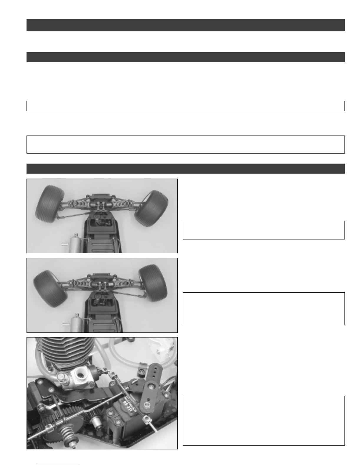
Step 2: Double-Check the Steering and Throttle/Brake Controls
❑ With the transmitter and the receiver turned on, rotate your
transmitter's wheel forward (to the right). The front wheels on the
X-Cellerator Racer should turn right.
✦✦
✦IMPORTANT
✦✦
reversing switch on your transmitter to change the direction.
❑ Rotate your transmitter's wheel backward (to the left). The front
wheels on the X-Cellerator Racer should turn left. Let go of the
wheel. The X-Cellerator Racer's wheels should return to center.
✦✦
✦ If the wheels don't turn right, flip the steering servo
✦✦
Need help or have any questions? Call us at 1-714-963-0329 or send us an Email at [email protected]
✦✦
✦IMPORTANT
✦✦
after you return the steering wheel to center, move the steering trim
lever on your transmitter to adjust the wheels so that they point
straight ahead.
❑ Carefully pull the air filter assembly off of your engine's carburetor.
❑ Pull back on your transmitter's throttle trigger. The carburetor barrel
should open completely and the brake should be disengaged.
❑ Let go of your transmitter's trigger and the carburetor barrel should
return to its idle position - open about 1/16". The brake should still be
disengaged.
✦✦
✦IMPORTANT
✦✦
pull back on the trigger, flip the throttle servo reversing switch on
your transmitter to change the direction.
If the carburetor barrel does not open completely, move the throttle
trim lever on your transmitter until the barrel is opened completely
when you pull back completely on the trigger.
✦✦
✦ If the wheels do not point straight ahead (center)
✦✦
✦✦
✦ If the carburetor barrel does not open when you
✦✦
11
Page 12
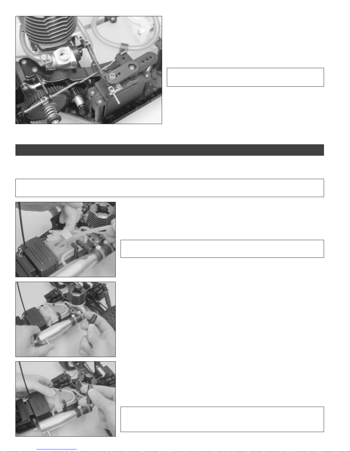
❑ Push your transmitter's throttle trigger forward. The carburetor
barrel should stay in the idle position and the brake lever should move
forward and engage the brake.
❑ Let go of the trigger and the brake lever should disengage.
✦✦
✦IMPORTANT
✦✦
page # 15 "Adjusting the Brake Linkage" for more details.
❑ Turn off your transmitter and receiver for now and push the air
filter back onto the carburetor. Never run your X-Cellerator Racer
without the air filter in place.
✦✦
✦ If you need to adjust the brake linkage, see
✦✦
SECTION 5: FUELING AND STARTING YOUR ENGINE
The following procedures show the general way to start a nitro engine mounted in the XTM Racing X-Cellerator Racer. The starting
procedures for your particular engine may differ. Make sure you are familiar with the starting and running procedures for your engine.
✦✦
✦IMPORTANT
✦✦
engine without the air filter installed. The air filter prevents dust and debris from entering the engine and damaging it.
✦✦
✦ The following photos show the air filter removed for clarity. Under no circumstances should you operate your
✦✦
❑ Lift the fuel tank lid and carefully fill the fuel tank until the fuel level is just below the top
of the tank.
✦✦
✦WARNING
✦✦
USE GASOLINE!
❑ Using your glow plug wrench, install and tighten a glow plug into your engine's
cylinder head.
❑ Prime the engine by first opening the throttle completely and covering the opening in the
tuned pipe with your thumb, then pull the pull-starter cord several times until you see
fuel just start to enter the carburetor through the fuel line.
❑ Remove your finger from the opening in the tuned pipe and close the throttle down to
the idle position.
❑ While holding the truck with one hand, carefully pull on the pull-starter cord several
times using short, quick pulls.
✦✦
✦ Use fuel that is appropriate for nitro car and buggy engines. DO NOT
✦✦
12
Visit our website at http://xtm.globalhobby.com or for Customer Service at http://globalservices.globalhobby.com
✦✦
✦IMPORTANT
✦✦
The engine is probably flooded. If so, check your engine's operating manual for
information on how to clear the engine's cylinder of excess fuel.
✦✦
✦ If you can't turn the engine over using the pull-starter, don't force it.
✦✦
Page 13
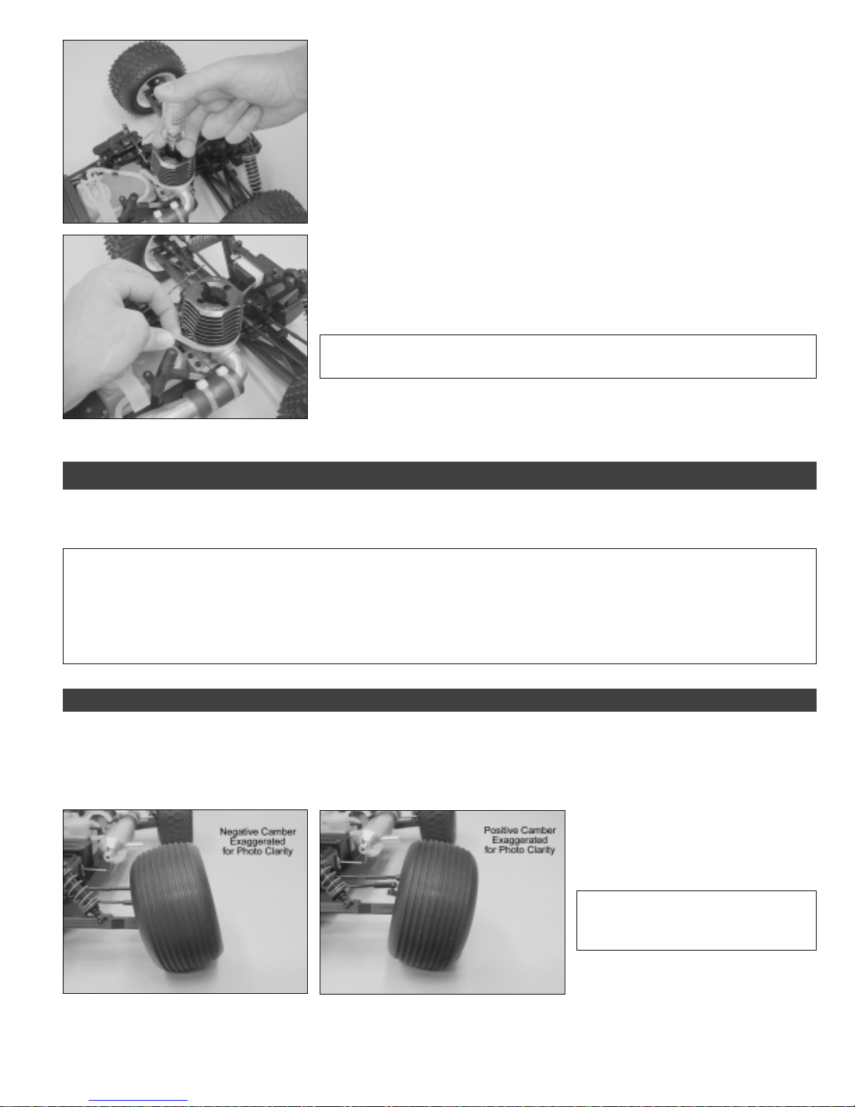
❑ Connect a fully charged glow starter to the top of the glow plug, making sure that the
glow starter is locked firmly onto the top of the glow plug. You don't want it to fall off while
you're trying to start your engine.
❑ While holding the truck with one hand, carefully start your engine.
❑ To stop your engine, carefully pinch the fuel line with your fingers until the engine
stops. Make sure to pinch the fuel pick-up line and not the fuel pressure line. The fuel
pick-up line is connected to the carburetor.
✦✦
✦WARNING
✦✦
✦✦
✦ Be careful not to touch any parts of the engine or tuned pipe because
✦✦
they will be hot.
SECTION 6: MAKING CHASSIS ADJUSTMENTS
Chassis alignment and geometry are important if you want your X-Cellerator Racer to perform well. A good performing truck means a
truck that is easier to drive, too. Follow our guidelines in this section to get the most out of your truck.
✦✦
✦IMPORTANT
✦✦
side. For example, if you change the camber angle on the right front tire, you should change the camber angle on the left front tire
the same amount. If you change the spring tension on the left front shock, you should change the spring tension on the right front
shock the same amount, and so on.
Do not make any changes that are more than 3 degrees from the initial settings listed or the handling characteristics of your truck will
become very poor.
Step 1: Adjusting the Camber Angle
Camber changes the amount of the tire's surface that contacts the ground. Tires that are exactly perpendicular to ground have 0
degrees of camber. If the top of the tires lean toward each other, the tires have negative camber. If the top of the tires lean out away from
each other, the tires have positive camber.
✦✦
✦ It's very important when making changes to the settings of your truck that you make the settings the same for each
✦✦
●
Adjust the camber angle of the front and/or rear wheels by turning the upper turnbuckles with the adjustment tool included.
Negative Camber
RECOMMENDED INITIAL CAMBER SETTINGS:
●
For driving on smooth surfaces set both the front and back wheels at 0 degrees.
●
For driving on rough surfaces set the front wheels at -1 degree and the back wheels at -2 degrees.
Need help or have any questions? Call us at 1-714-963-0329 or send us an Email at [email protected]
Positive Camber
Camber settings should be measured
☞
with the vehicle at its normal ride height.
✦✦
✦IMPORTANT
✦✦
✦✦
✦ For more precise
✦✦
camber adjustments, use the R.P.M.
Precision Camber Gauge part # 708099.
13
Page 14
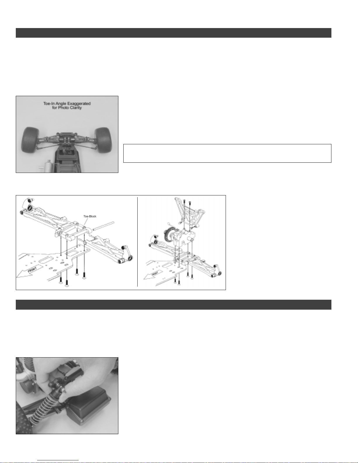
Step 2: Adjusting the Toe Angle
The toe angle is the angle of both front tires (or rear tires) to each other, when viewed from above. Toe-in is when the front of both tires
point toward each other and toe-out is when the front of both tires point away from each other.
●
For the front tires, toe-in will make your truck track straighter, but the steering will be more sensitive. Toe-out will desensitize the
steering, making the truck a little more driver-friendly.
●
For the rear tires, if you're running on a smooth surface, we suggest no toe-in. If you are running on a rough surface, we suggest about
1 - 2 degrees of toe-in. This will give the rear end a little more "bite."
RECOMMENDED INITIAL SETTINGS:
●
1-2 degrees toe-in on the front to add stability.
Adding more than 3 degrees of toe-in or toe-out will result in excessive loss of speed
☞
and erratic handling.
✦✦
✦IMPORTANT
✦✦
✦✦
✦ For more precise toe-in adjustments, use the R.P.M. Toe-in Gauge
✦✦
part # 708049.
To adjust the toe-angle of the front tires, turn the tie-rods in or out with the adjustment tool included. To adjust the toe angle of the rear
tires, you need to replace the toe angle block, using the reference below:
The X-Cellerator Racer kit includes three
different toe-blocks. One 1º, one 2º and one
4º toe-block. The 1º toe-block is installed
from the factory.
To adjust the toe-in on the rear tires, use
one of the different composite toe angle
blocks provided in your kit to set the desired
toe angle. For convenience, the degree of
toe angle in each block is molded into the
back of the blocks.
Step 3: Adjusting Shock Spring Tension
By adjusting the spring tension of the shocks, you can increase steering sensitivity and increase the ride-height of your vehicle. How you
drive your vehicle will dictate what settings you should be using. As an example, if you're using your vehicle off-road and going over lots
of jumps, you may want to increase the spring tension of the front shocks to help prevent the front of the vehicle from bottoming out.
●
Increase or decrease spring tension by threading the adjustment ring up or down the shock shaft. Threading the ring down increases
spring tension, threading the ring up decreases spring tension.
RECOMMENDED INITIAL SETTINGS:
●
We recommend initially leaving the adjustment rings in the factory locations.
☞
14
Visit our website at http://xtm.globalhobby.com or for Customer Service at http://globalservices.globalhobby.com
When adjusting the spring tension, make sure to adjust the right and left sides equally.
Page 15
Step 4: Adjusting Shock Dampening & Shock Body Mounting Location
Changing the shock oil (the oil inside the shocks) will change the dampening characteristics of the shocks. Typically, if you are running
on smooth surfaces, use a heavier weight oil. If you are running on rough surfaces, use a lighter weight oil.
✦✦
✦IMPORTANT
✦✦
✦✦
✦ We recommend using only 100% Silicone Shock Oil. Do not use motor oil. The shock oil in the X-Cellerator Racer's
✦✦
shocks is good for most off-road applications.
Moving the upper mounting position of the rear shocks to a hole in the shock tower that results in the shock assembly being more upright
will result in more "bite" in the rear of the vehicle.
Step 5: Adjusting the Slipper Clutch
The slipper clutch is a traction control device that uses two metal plates and two fiber pads to control how much power is transmitted from
the engine to the gear box and drive-train. Adjusting the slipper clutch allows you to fine tune how your vehicle reacts when giving it
throttle. Driving the vehicle with the slipper clutch too tight will usually result in the vehicle doing wheelies or spinning out of control
instead of accelerating. Driving the vehicle with the slipper clutch too loose will result in very poor or no acceleration at all.
●
To adjust the slipper clutch you simply turn the hex nut either in to tighten the clutch (less slip) or out to loosen the clutch (more slip).
After making each adjustment, accelerate the vehicle for a short distance while carefully watching the slipper clutch. Ideally the clutch
should slip for about the first foot after acceleration.
RECOMMENDED INITIAL SETTINGS:
●
Tighten the hex nut completely and back it off 5 turns.
✦✦
✦IMPORTANT
✦✦
very quickly and replacement under this circumstance will not be covered under warranty.
✦✦
✦ Running the slipper clutch too loose can cause the fiber pads to wear out
✦✦
Step 7: Adjusting the Ball Differential
The ball differential should be adjusted after the first couple of runs. After that, it should require very little adjustment - only to fine-tune
the differential to your driving style or track.
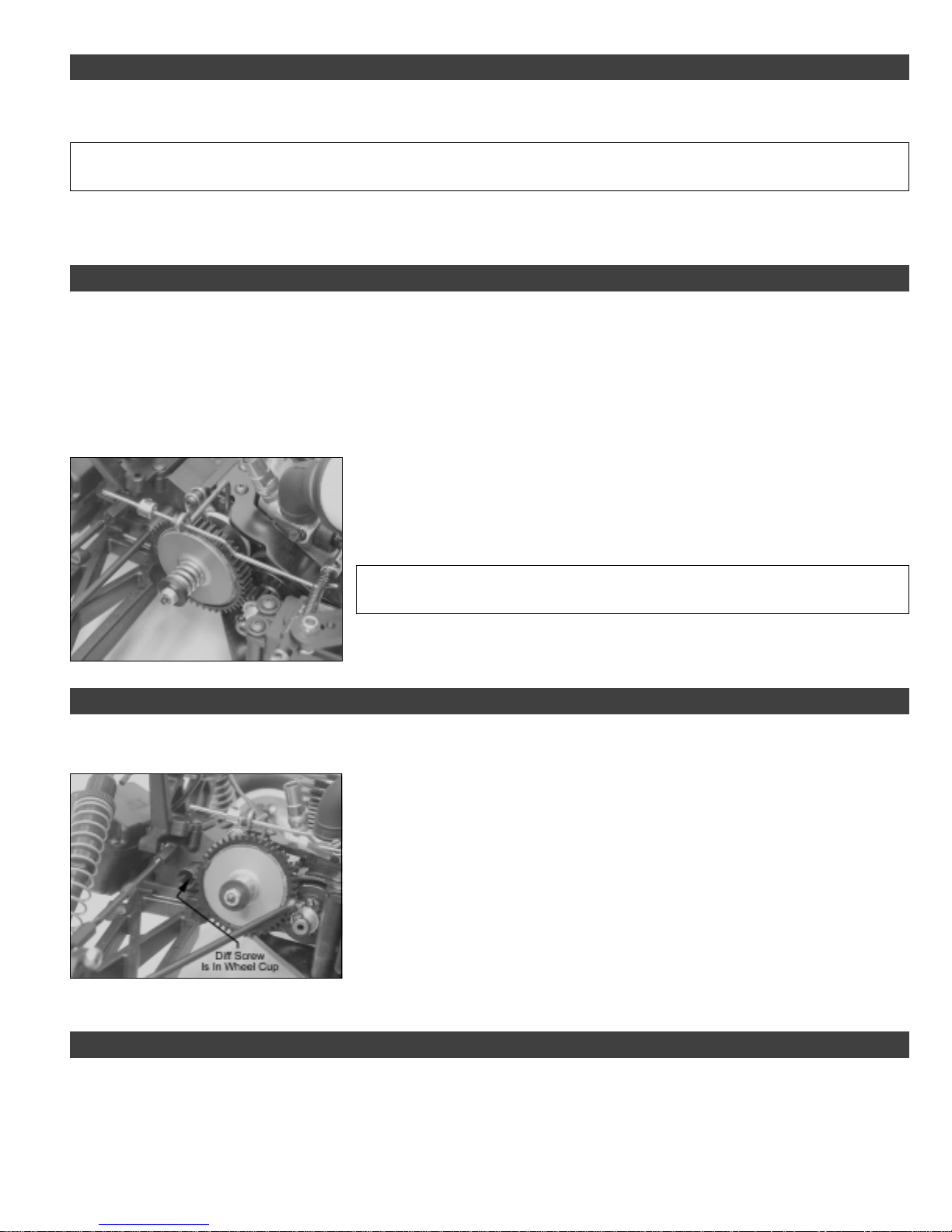
●
To adjust the differential you will need to pull the passenger's side axle from the drive
cup. To do this, first remove the wheel from the axle, then remove the shock assembly
from only the shock tower. Second, lower the suspension arm down as far as possible
and the axle should come out of the drive cup.
●
After the axle is removed from the drive cup, use a small screwdriver to pop out the
nylon plate that is inside the drive cup.
●
While holding the opposite wheel with one hand, use a 5/64" (2mm) hex wrench to
tighten or loosen the hex screw in the center of the drive cup, until you're satisfied with the
operation of the differential.
●
After adjusting the differential, reinstall the assemblies in the reverse order of removal.
Step 6: Adjusting the Brake Linkage
With the transmitter and receiver turned on, and the throttle/brake trim lever centered, the truck should roll smoothly (i.e., the brake
should be disengaged). If the brake is dragging when the throttle trigger is at neutral, the brake disc will wear out very quickly. To
ensure that the brake is disengaged, always make sure that there is a 1/8" gap between the linkage collar and the brake lever.
●
To make adjustments to the brake, simply loosen the grub screw in the wheel collar next to the brake lever and reposition it, then
retighten the grub screw.
Need help or have any questions? Call us at 1-714-963-0329 or send us an Email at [email protected]
15
Page 16

SECTION 7: MAINTAINING YOUR X-CELLERATOR RACER
Following a simple maintenance schedule will ensure that your X-Cellerator Racer operates in top condition every time you use it. It is
strongly suggested.
●
Check the foam air filter element for dirt blockage. If the foam
is dirty, remove it from the filter housing and wash it in liquid soap
and warm water. Dry the foam element with a paper towel,
reinstall it and "wet" it with after-run oil. Make sure to clean or
replace the prefilter, too.
●
Check the chassis for any loose screws, especially the engine
and tuned pipe mounting screws. Tighten them if necessary.
●
Check the steering linkage and the throttle/brake linkage for
any signs of wear or misalignment. Tighten and/or readjust them
if necessary.
●
Once in a while, remove the wheels and clean the wheel bearings
using a bearing cleaner. This will remove any dust and grit that
may, over time, damage the bearings. After cleaning the
bearings, re-oil them using a good quality bearing oil. Never run
the bearings dry or damage to the bearings will result.
●
Check the fuel system, including the fuel tank and fuel lines,
for any signs of cracking or looseness. Replace any fuel line you
suspect may be damaged.
●
You should periodically check and adjust the slipper clutch as
described on page # 15.
●
After a period of time the chassis will accumulate a lot of dirt
and debris, especially around the engine area. This build-up
should be cleaned off using a high-powered spray cleaner like
Emerald Nitro Car Cleaner. Some nitro car cleaners will damage
anodized and/or plated parts. Test on an inconspicuous
area first.
●
After cleaning the chassis and engine with Nitro Car Cleaner
you should oil the moving parts of the chassis. Do not oil the
clutch bell, spur gear or the brake disc.
●
Always use new fuel and keep the cap on the fuel tightly closed.
As fuel ages it absorbs water, which degrades the fuels performance
and will cause erratic engine operation.
●
After you have finished using the engine for the day, remove
the glow plug and squirt several drops of a high-quality after-run
oil into the cylinder. Reinstall the glow plug and crank the engine
over a couple of times (without the glow starter attached) to
distribute the oil. This will prevent corrosion inside the engine.
●
Never leave unused fuel in the fuel tank for more than a couple
of days. The nitromethane and methanol in the fuel will
evaporate, leaving the oil behind. This will eventually turn into a
thick sludge that will require replacement of the fuel tank to fix.
16
Visit our website at http://xtm.globalhobby.com or for Customer Service at http://globalservices.globalhobby.com
Page 17

SECTION 8: TROUBLESHOOTING GUIDE
This troubleshooting guide has been provided to help you diagnose and solve most problems that you may encounter with your X-Cellerator
Racer. Most problems encountered can be solved by carefully following the problem-cause-solution sections. If you cannot solve the
problem using this troubleshooting guide, please feel free to contact us at the address, phone number or email address shown on the
second page of this Assembly Manual.
PROBLEM CAUSE SOLUTION
1) Vehicle pulls to one side A) Steering trim out of adjustment A) Readjust trim to center both wheels
B) Toe angle out of adjustment B) Readjust toe angle
C) One wheel is hanging or has damaged bearing C) Remove wheel and clean bearing. Replace if necessary
2) Brake seems ineffective A) Brake linkage out of adjustment A) Readjust brake linkage
B) Brake disc worn B) Replace brake disc
3) Clutch does not engage A) Clutch shoes damaged or worn A) Replace clutch shoes
B) Clutch bell damaged or worn B) Replace clutch bell
4) Clutch does not disengage A) Clutch spring worn or damaged A) Replace clutch spring
5) Truck does not "go" A) Stripped spur gear A) Replace spur gear
B) Stripped differential gear(s) B) Replace differential gear(s)
C) Slipper clutch set too loose C) Readjust slipper clutch until truck accelerates smoothly
D) Clutch shoes slipping D) Clean clutch bell as described on page # 6, step # 5
and carefully remove any "glaze" from the clutch
shoes, suing the same method
6) Truck wheelies or flips A) Slipper clutch set too tight A) Readjust slipper clutch until truck accelerates smoothly
over backwards
7) Suspension not smooth or free A) One or more shocks sticking A) Clean and/or rebuild the affected shock
B) Bent shock shaft B) Rebuild affected shock
C) Bent or otherwise damaged hinge pin C) Replace hinge pin
8) Shocks leaking oil A) Shock seals worn A) Replace shock seals
B) Bent shock shaft B) Rebuild affected shock
Need help or have any questions? Call us at 1-714-963-0329 or send us an Email at [email protected]
17
Page 18

18
Visit our website at http://xtm.globalhobby.com or for Customer Service at http://globalservices.globalhobby.com
Page 19

Need help or have any questions? Call us at 1-714-963-0329 or send us an Email at service@globalhobby.net
19
Page 20
IMPORTANT WARRANTY INFORMATION - PLEASE READ!
Your XTM Racing X-Cellerator Racer is warranted against manufacturer defects in materials and workmanship for a period of 90 days
from the date of purchase. Warranty service will be provided within 90 days of the date of purchase only if you are able to provide the
original or a copy of the original dated sales receipt.
IMPORTANT WARRANTY SERVICE INFORMATION
Before returning your X-Cellerator Racer for warranty consideration, the status of the unit must be within the guarantee as stated above.
Do not return your X-Cellerator Racer to the place of purchase. They are not authorized or equipped to perform warranty work on XTM
Racing products. When requesting warranty service, please observe the following:
●
Crash damage will not be covered under warranty. Do not request warranty service for a crash-damaged product.
●
This warranty only covers the XTM Racing X-Cellerator Racer. It does not cover your own engine or radio control system. Please
remove your engine, radio control system and batteries from the chassis before sending the product to us.
●
Include a note detailing the problem or service you are requesting. Service cannot be provided without this information. Include your
daytime phone number, shipping address and/or email address in the event we need more details pertaining to the service requested.
●
If your vehicle is out of the warranty period you may request an estimate of services at the time you return your vehicle for service. An
omission of this request implies permission for Global Services to service your vehicle at our discretion.
●
Include a method of payment for any service charges.
●
Send the unit to us by United Parcel Service, Federal Express or by Insured Mail. Postage is non-refundable. Send your package to:
Global Services
18480 Bandilier Circle
http://globalservices.globalhobby.com
Visit Our Website
Fountain Valley CA 92708
Phone: (714) 963-0329 Fax: (714) 964-6236 Email: [email protected]
PURCHASING REPLACEMENT PARTS
Included with your X-Cellerator Racer is a separate booklet listing all of the replacement parts that are, along with their respective
part numbers. Replacement parts are available through your local authorized XTM Racing dealer or directly from us.
To locate the dealer nearest you, please call us at (714) 963-0133 or visit our dealer directory on the Internet at
www.globalhobby.com/where2buy.htm
or Order Directly From Us at the Address, Phone Number or Web Site Shown Above
20
Visit our website at http://xtm.globalhobby.com or for Customer Service at http://globalservices.globalhobby.com
 Loading...