

Page 1
XL-VC102MB
VDSL CO/Master bridge
User’s Guide
Page 2

XtendLan VC102MB – User’s Guide http://www.xtendlan.com
Contents
1 VDSL POINT TO POINT SOLUTION.....................................................................................................................................3
2 PRODUCT FEATURES & SPECIFICATION.........................................................................................................................5
3 UNPACKING INFORMATION.................................................................................................................................................7
4 INSTALLING THE MODEM....................................................................................................................................................8
5 HARDWARE DESCRIPTION.................................................................................................................................................10
6 CONFIGURATION SOFTWARE DESCRIPTION...............................................................................................................12
6.1 START-UP DIALOG...............................................................................................................................................................12
6.1.1 General Settings Page....................................................................................................................................................12
6.1.2 Link Configuration Page................................................................................................................................................13
6.1.3 Write-Update Message Box............................................................................................................................................15
6.1.4 VDSL PHY Status Page..................................................................................................................................................17
6.1.5 Ethernet Status Page......................................................................................................................................................19
6.2 ADDITIONAL DIALOGS.........................................................................................................................................................21
6.2.1 Terminal Window...........................................................................................................................................................21
6.2.2 Set to Default Dialog......................................................................................................................................................22
6.2.3 About / Version Info Dialog...........................................................................................................................................22
6.2.4 Error - Hardware does not respond...............................................................................................................................23
4.3.5 Error - COM port not accessible...................................................................................................................................23
6.2.5 File Menu.......................................................................................................................................................................24
6.2.6 Window Menu ................................................................................................................................................................24
7 GLOSSARY................................................................................................................................................................................25
8 APPLICATIONS........................................................................................................................................................................25
9 CABLE REQUIREMENTS ......................................................................................................................................................26
10 TROUBLESHOOTING.............................................................................................................................................................27
10.1 DISABLE AND ENABLE VDSL CPE MODEM LINK WATCH DOG (LWD)..............................................................................29
10.2 SPEED CHANGE QUICK GUIDE...............................................................................................................................................33
11 COMPLIANCE AND SAFETY INFORMATION.................................................................................................................36
- 2 -
Page 3

XtendLan VC102MB – User’s Guide http://www.xtendlan.com
1 VDSL Point to Point Solution
The VDSL (Very High Data Rate DSL) networking solution delivers cost-effective,
high-performance broadband access to multiunit buildings (hotels, apartment, and
multi-tenant unit office buildings) and enterprise campus environments such as
manufacturing, educational campuses, and medical facilities. VDSL technology dramatically
extends Ethernet over existing Category 1/2/3 wiring at speeds 10Mbps (full duplex) and
distances up to 1200 meters. The VDSL technology delivers broadband service on the same
lines as Plain Old Telephone Service (POTS), digital telephone, and ISDN system. In
addition, VDSL supports modes compatible with asymmetric digital subscriber line (ADSL),
allowing service providers to provision VDSL to buildings where broadband services already
exist.
The VDSL solution includes VDSL Concentrator (VDSL switches), VDSL CO(Point to Point),
and VDSL Modem for Customer Premise Equipment (CPE) device.
The VDSL solution delivers everything needed to quickly deploy an Ethernet-based network
with the performance required to deliver high-speed Internet access at much greater
distances and drive services like IP telephony and audio/video streaming. With this
technology, a broad range of customers can benefit from lower operating costs and rapid
deployment. This solution provides a RS-232C console port for monitoring
VDSL status and to configure speed.
This device is a CO side solution, and bridge between external Internet backbone through
a router for IP sharing and the building 110D telephone rack or telephone box. It utilizes the
available telephone wire to enable high-speed Internet access to building residents.
VDSL Modem uses the phone line networking technology endorsed by the VDSL, and utilizes the
already existing telephone wire to deliver 4/1, 5/10/15 Mbps Internet access on each RJ-11 port.
This gives users a low-cost, end-to-end solution and eliminates the need to train installation teams
on multiple systems.
Foreword
XL-VC102MB is an Ethernet to VDSL CO side adapter that enables high speed internet
access to building residents, campuses students and hotel guests by connecting Ethernet
equipped computers, set-top box or any internet access device to the existing telephone
wires.
The VDSL Modem uses the phoneline networking technology endorsed by the VDSL, an
association of industry-leading companies for in– networking focus on the existing telephone
- 3 -
Page 4

XtendLan VC102MB – User’s Guide http://www.xtendlan.com
wire.
The Modem utilizes the already existing telephone wire to deliver 10Mbps internet access
with no interference on the existing telephone service. It allows user to make calls while
access the internet on the same wire simultaneously. It even allows staying connected 24
hours on internet connections, thus, eliminating dial up prior to internet access.
The Modem is simple to install and use. One RJ-45 Ethernet connects to a Router, Ethernet
Switch or to LAN card. The RJ11 ports available to connect to any existing modular phone
jack.
There are two RJ-11 jack on the Modem to provide a phone extensions.
No software installation makes the Modem highly compatible with different operating system
( Windows, Linux, Apple….etc).
- 4 -
Page 5

XtendLan VC102MB – User’s Guide http://www.xtendlan.com
2 Product Features & Specification
Model Name: XL-VC102MB
Description: VDSL Modem with C.O. side (Master)
Features:
¾ Compliant with IEEE 802.3 & 802.3u Ethernet Standards
¾ Compliant with ETSI, ITU, ANSI VDSL standards
¾ Provides 1 x 10/100M auto-sensing RJ-45 Ethernet ports
¾ Supports Bandwidth setup with 4/1,5/10/15 Mbps VDSL RJ-11 ports
¾ POTS / ISDN Splitter port RJ-11 x 1 (Splitter on board)
¾ Ethernet transport with POTS / ISDN traffic over single copper wire pair
¾ Spectral compatibility with XDSL, ISDN(2B1Q/4B3T).
¾ Robust operation on severely distorted line
¾ Supports console port for function setup
¾ Supports write default value
¾ Supports remote CE side from CO side console
¾ Provides configuration utility software
¾ Provides Ready LED.
¾ Provides LED indication Link/Active Status for Ethernet port.
¾ Provides LED indication Link for VDSL port.
Specifications:
¾ Compliant with IEEE 802.3 & 802.3u Ethernet Standards
¾ Compliant with ETSI, ITU, ANSI VDSL standards
¾ 10/100M auto-sensing RJ-45 Ethernet ports x 1
¾ 4/1, 5/10/15 Mbps VDSL RJ-11 port x 1
¾ POTS / ISDN Splitter port RJ-11 x 1
¾ Consol port RJ-45 x 1
¾ Surge Protection
¾ Switch method : store and forward
¾ Flow control Full duplex : IEEE 802.3x Half duplex : Backpressure
¾ Driver capable :
o 4/1Mbps: 1.9km
o 5Mbps :1.5km
o 10Mbps : 1.2km (Default)
o 15Mbps : 1km
¾ Indication LED x 3: Ready LED x1, Ethernet Link/Active LED x 1, VDSL Link LED x 1
¾ Console port : RS-232C/ 9600 bps
¾ VDSL Frequency Spectrum :
o Transmitter :0.9 ~ 3MHz
o Receiver:4.5 ~ 7.9 MHz
o Splitter : 0 ~ 620k
¾ Power consumption : 2.5 Watt
Weight : 345 g
¾
- 5 -
Page 6

XtendLan VC102MB – User’s Guide http://www.xtendlan.com
¾ Dimensions: 95 x 110 x 24 mm
¾ External switching power adapter Input :AC 100-240 volts/50-60Hz Output :DC 5V/1A
or above
o
¾ Operating Temperature : 0
¾ Storage Temperature : - 20
C ~ 50 oC (41F ~ 122F)
o
C ~ 65 oC (-4F ~ 149F)
¾ Humidity : 10%~90% non-condensing
Certifications : FCC, CE Mark class A, EN60950
- 6 -
Page 7

XtendLan VC102MB – User’s Guide http://www.xtendlan.com
3 Unpacking Information
Carefully unpack the package and check its contents against the checklist.
Package Contents:
¾ VDSL CO x 1
¾
Four plastic feet x 4
¾
AC To DC Power Adapter x 1
¾
RJ-45 cable x 1
¾ RJ-11 cable x 1
¾ RJ-45 To D-SUB Cable x 1
Please inform your dealer immediately for any missing items, or damaged parts. If possible, retain
the carton, including the original packing materials. Use them to repack the unit in case there is a
need to return for repairing.
- 7 -
Page 8

XtendLan VC102MB – User’s Guide http://www.xtendlan.com
4 Installing the Modem
Hardware Installation
This chapter describes how to install the Modem and establishes network connections. You
may install the Modem on any level surface (e.g, a table or shelf). However, please take note
of the following minimum site requirements before you begin. Stick the 4 plastic feet at the
bottom to avoid scratches.
Pre-installation Requirements
Before you start the actual hardware installation, make sure you can provide the right
operating environment, including power requirements, sufficient physical space, and
proximity to other network devices that are to be connected.
Verify the following installation requirements:
Power requirements: DC 5V/1A or above
The Modem should be located in a cool dry place, with at least 10cm/4in of space at the front
and back for ventilation.
Place the Modem out of direct sunlight, and away from heat sources or areas with a high
amount of electromagnetic interference.
Check if network cables and connectors needed for installation are available
Connecting the Modem
The Modem has one Ethernet port which support connection to Ethernet operation. The devices
attached to these ports must support auto-negotiation or 10Base-T OR 100Base-TX unless they will
always operate at half duplex.
Use any of the Ethernet ports to connect to devices such as NIC, Switch, bridge or router. You can
also connect to another compatible Modem to an RJ-45 port on the other device.
The RJ11 Line port is used to connect to the wall RJ-11 modular socket which is connect to VDSL
CPE Modem side (Point to point solution)
The RJ11 Phone port of the Modem can connected to a telephone and a computer sharing one
telephone wire for making calls and accessing the internet at the same time
Connecting the RJ-11/RJ-45 Ports
The Modem’s RJ-11 ports support the transmission of data up to 4/1, 5/10/15Mbps across existing
phone wiring, without interfering with standard voice transmissions, easy-to-use does not require the
installation of any additional wiring. Every RJ-11 modular phone jack in the home can become a port
on the LAN. Networking devices can be installed on a single telephone wire that can span within
1.9/1.5/1.2/1km (depend on speed) between the two farthest points.
- 8 -
Page 9
XtendLan VC102MB – User’s Guide http://www.xtendlan.com
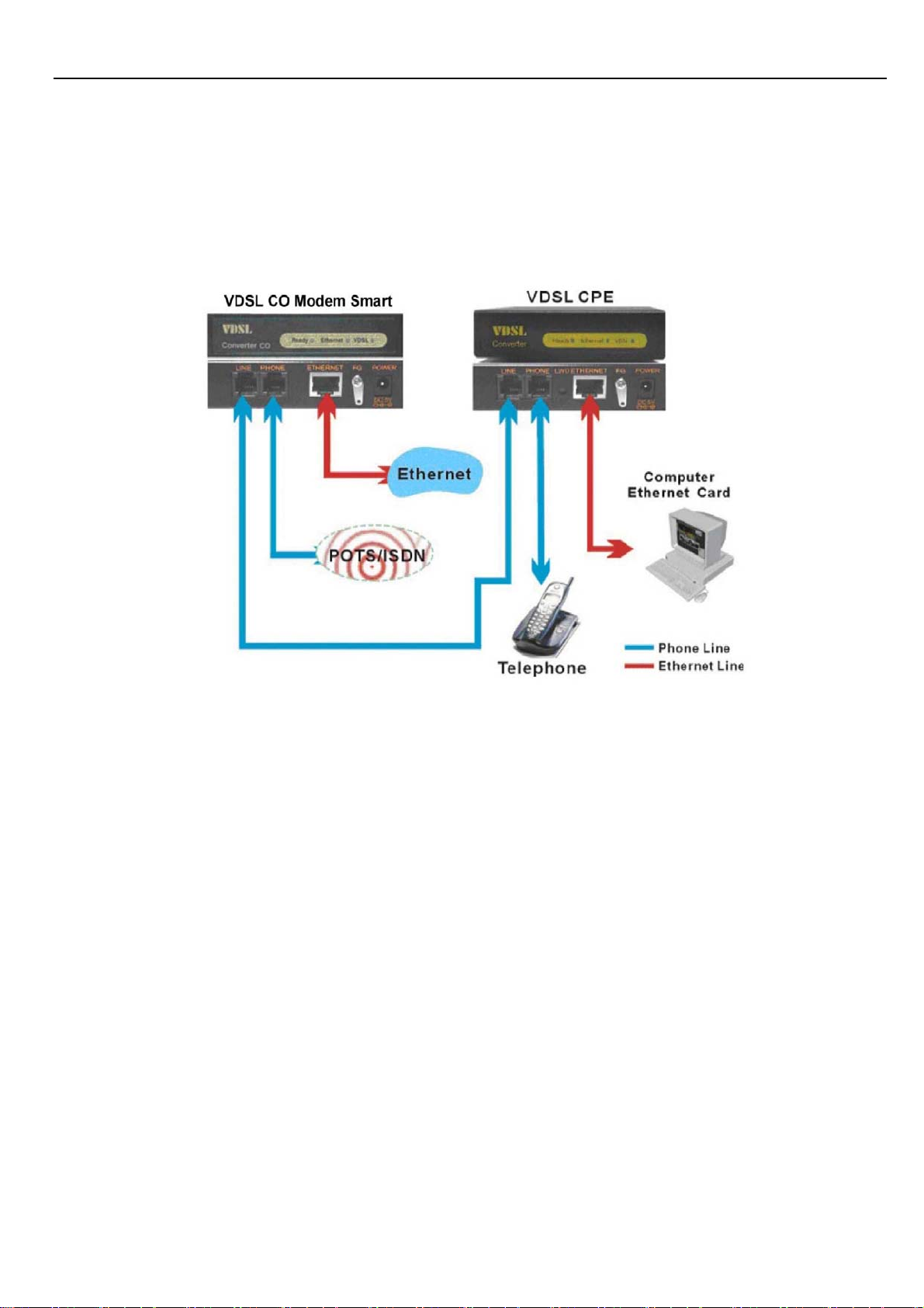
VDSL CO Modem has embedded Splitter between every VDSL side (Line) and POTS (Phone) side.
It permit you can delivers broadband service on the same lines as Plain Old Telephone Service
(POTS), PBX, ISDN traffic and VDSL Signal.
Scheme: XL-VC102MB as CO modem and XL-VC102SB as CPE modem
The RJ-11 port support 4/1,5/10/15 Mbps connections. When inserting a RJ-11 plug, be sure the tab
on the plug clicks into position to ensure that it is properly seated.
4.Do not plug a RJ-11 phone jack connector into the Ethernet port (RJ-45 port). This may damage
the Modem Instead; use only twisted-pair cables with RJ-45 connectors that conform to Ethernet
standard.
Notes:
Be sure each twisted-pair cable (RJ-45) does not exceeds 100 meters (333 feet).
RJ-11 port use 24 ~ 26 gauge phone wiring, we do not recommend 28 gauge or above.
We advise using Category 3,4,5 cable for Cable Modem or Router connections to avoid any
confusion or inconvenience in the future when you upgrade attached to high bandwidth
devices.
- 9 -
Page 10

XtendLan VC102MB – User’s Guide http://www.xtendlan.com
5 Hardware Description
This section describes the important parts of the Modem. It features the front indicators and
rear connectors.
Front Indicators
The following figure shows the front panel:
At a quick glance of the front panel, it is easy to tell if the CO Modem has power, if it has
signal from its Ethernet RJ-45 port and if there is phone line signal on RJ-11port
LED Description and Operation:
LEDs Status Descriptions
Ready
(Ready LED)
Steady Green
It will light up (ON) to show that the product is
power good, and system reset OK.
Ethernet
(Ethernet LED)
VDSL
(VDSL LED)
Steady Green
Flashing
(LINK/ACT)
Steady Green
Each RJ45 station port on the Ethernet is
assigned an LED light for monitoring port “Good
Linkage”. LED is normally OFF after the power
on operation, but will light up steadily to show
good linkage and flashing to show data
transmission.
RJ11 station port on the VDSL is assigned an
LED light for monitoring port “Good Linkage”.
LED is normally OFF after the power on
operation, but will light up steadily to show good
linkage.
- 10 -
Page 11
XtendLan VC102MB – User’s Guide http://www.xtendlan.com
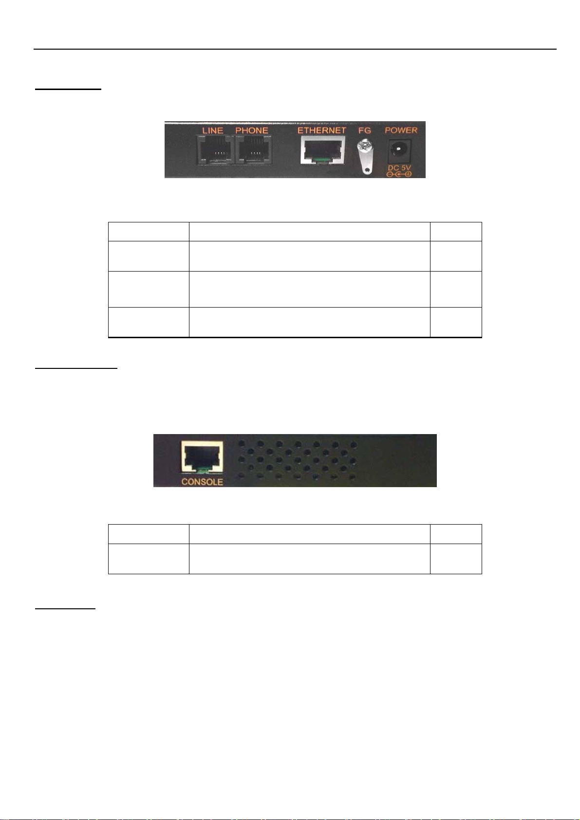
Rear Panel
The following figure shows the rear connectors
Table Modem Rear Connectors
Connectors Description Type
Line
For connecting to the VDSL Modem
Using a RJ-11 cable
RJ-11
For connecting to the telephone or Fax 、
Phone
RJ-11
ISDN modem
Ethernet
Left side view
The following figure shows the left side connectors. You can adjust VDSL Speed and Monitor VDSL
status from console
For connecting to a Ethernet equipped
device
Table Modem Rear Connectors:
RJ-45
Connectors Description Type
Console
Power On
1. Check the adapter is properly connected.
2. Verify the power LED is steadily on.
For connecting to PC with RS-232 seriál
port over RJ-45 To D-DUB Cable
RJ-45
- 11 -
Page 12

XtendLan VC102MB – User’s Guide http://www.xtendlan.com
6 Configuration Software Description
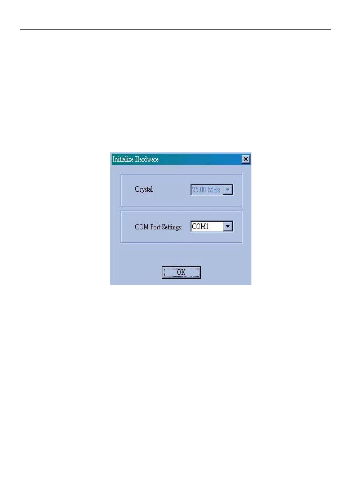
6.1 Start-up Dialog
When the software is started, the user has to adjust the COM port setting for which is
connected to.
6.1.1 General Settings Page
The general settings page allows basic settings. Both, local and remote modem (if available and
synchronized) can be addressed by this window.
- 12 -
Page 13

XtendLan VC102MB – User’s Guide http://www.xtendlan.com
Following functions are supported on the General Settings page:
Modem Type Display: Indicates which modem type (LT or NT) is the local and remote modem.
Reset: Performs a soft reset of the modem. After a soft reset, the 10BaseS-D is held in reset state
for 256 clocks.
Local Loop back: Returns data from the Tx port of the 10BaseS-D to the Rx port of the 10BaseS-D.
The transmitted data to the line is not guaranteed when the local loop back is activated. This feature
is not supported on the far-end modem, since this would bring down the link
Line Loop back: Connects the output port of the VDSL TC-layer to the TC-layer input. This loop
back contains the Ethernet interface, the scrambler, the Reed Solomon block, interleaver, framer
and synchronizer.
Turn transmitter on/off: This button turns the transmitter on/off in case a VDSL link is not
established. This feature serves for test purposes, e.g monitor the spectrum with a spectrum
analyzer.
Activation disable/enable: This button enables the user to enable or disable the VDSL link
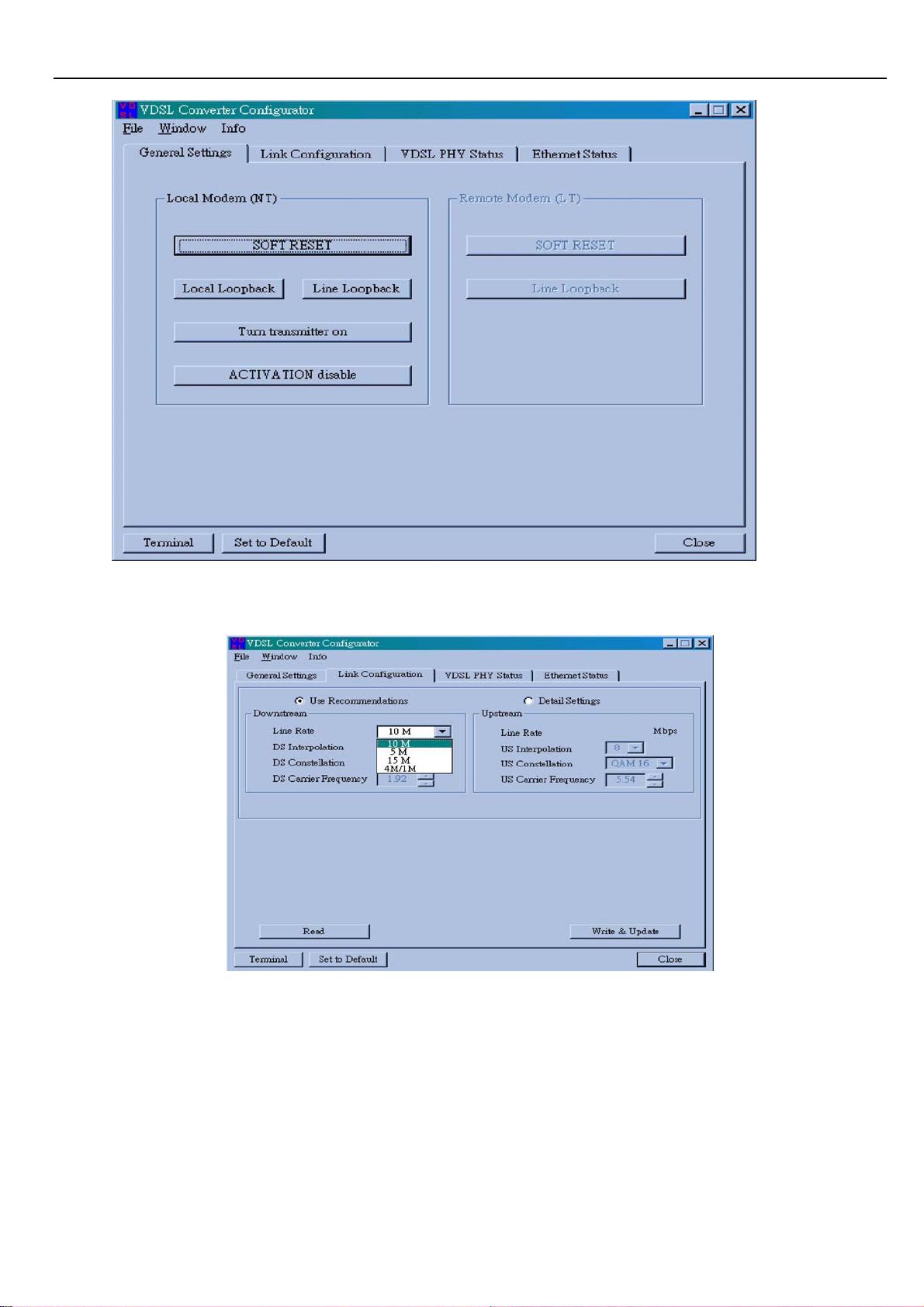
6.1.2 Link Configuration Page
The Link Configuration window shown in figure allows access to the PMD (Physical Media
Dependent) registers of the VDSL. Both, local and remote modem (if available and synchronized)
can be addressed by this window.
- 13 -
Page 14

XtendLan VC102MB – User’s Guide http://www.xtendlan.com
The following functions are available within the Link Configuration page:
Customized Settings:
If this option is selected, the user has access to the whole bandwidth of adjustable constellations
and interpolations as well as the carrier frequencies. So he can easily find the appropriate line rate
for his special application.
Standard settings:
In this option the user can select a couple of approved constellations, interpolations and carrier
frequencies to change the line rate of the modem. We support the following modes:
• 4/1 M asymmetrical rate (up to 1900 meters)
• 5 M symmetrical rate (up to 1500 meters)
• 10 M symmetrical rate (up to 1200 meters)
• 15 M symmetrical rate (up to 1000 meters)
Change Speed procedures:
• Connecting both VDSL CO and VDSL CPE.
• Make sure VDSL CO has already connected to VDSL CPE, please check both VDSL
LEDs are light up
• Select the Upstream and Downstream speed mode (4/1M, 5 M / 10 M / 15 M)
• Click “Write & Update” to confirm the settings
• The VDSL port LED will be link down temporarily about 30~60
- 14 -
Page 15

XtendLan VC102MB – User’s Guide http://www.xtendlan.com
seconds.
• Then the VDSL link LED will be re-linked up. It means that the new speed mode has
been changed successfully.
Note: manufacturing default speed is on 10Mbps mode.
Line Rate Throughput:
4/1M Line Rate= 4.17/1.56 Mbps
5M Line Rate= 6.25 Mbps
10M Line Rate=12.5 Mbps
15M Line Rate=16.67 Mbp
Configuring Modem Ethernet Port (Nway)
You can change Modem Ethernet port "Advertisement Argument" from the Switch when the port is
linked. There are 4 modes of the Advertisement Argument that will be used in the Ethernet Auto
Negotation procedure: 1.{10M Half}, 2.{10M Full} 3.{100M Half} 4.{Auto}.
10M Half Ethernet can only link by 10Mbps Half duplex
10M Full Ethernet can link by 10Mbps Half and 10Mbps Full duple
100M Half Ethernet can link by 10Mbps Half, 10Mbps Full duplex and 100Mbps Half
duplex. This is default setting
Auto Ethernet Auto Negotiation by 10Mbps Half, 10Mbps Full duplex, 100Mbps
Half duplex and 100Mbps Full duplex
Example: If you want modem Ethernet port to link at 10Mbps Half, you can select " 10M Half ". If
you want modem Ethernet port to link at 100Mbps Full, you can select " Auto "
6.1.3 Write-Update Message Box
After pressing button “Write & Update” the message box shown in
Pressing “OK” causes the following actions:
- 15 -
Page 16

XtendLan VC102MB – User’s Guide http://www.xtendlan.com
If a VDSL link is established the software changes all registers in the remote modem and then the in
the local modem. If no VDSL link is established the changes are only applied to the local modem
Pressing “CANCEL” closes the box without changes.
6.1.3.1 Read Message Box
After pressing button “Read”, System will show current Downstream and Upstream status
of Line Rate, Interpolation, Constellation and Carrier Frequency.
- 16 -
Page 17

XtendLan VC102MB – User’s Guide http://www.xtendlan.com
6.1.4 VDSL PHY Status Page
The VDSL PHY Status page shown in figure represents the current link status of the local
modem. This window is refreshed each five seconds.
The status page shows the following values:
SNR of Received Signal: The SNR of the received signal is calculated from the parameters found
in the PMD layer. The SNR calculation depends on the QAM constellation of the eceived signal.
Followings are the good SNR readings (db) for each of the standard line rates in VDSL CO:
4/1M >=19dB
5M >=25dB
10M >=25dB
15M >=37dB
Mean Square Error: The mean square error is an indication of the symbol error rate. Its
calculation depends on the QAM constellation and the SNR of the received signal
- 17 -
Page 18

XtendLan VC102MB – User’s Guide http://www.xtendlan.com
Corrected RS Error(s): This field gives the number of corrected Reed Solomon errors per
second. It is an indication of the bit error rate on the line due to disturbers.
Transmit Power: This field shows the actual transmitted power level. On RT modems with
PBO enabled this value may be different from the minimum and maximum PSD level
adjusted on the Link Configuration Page
Full Constellation Link: Full constellation link is working and the modem can transmit and
receive data
ٛ
Reduced Constellation Link: The modem has synchronized in reduced constellation
(QAM4) only. In this state the VDSL Operating Channel (VOC) is working and the VOC
channel can be used to re-configure the link.
TC Synchronized: Indicates that the transmission convergence layer (TC) is synchronized.
VDSL frame acquisition is working and the modem is in SYNC state
Ethernet Encapsulation Sync: Indicates that the Ethernet data path machine has
synchronized. In this state payload data transmission is
working.
Remote I/F Synchronized: Indicates that the remote data interface is synchronized.
Signal Detected: Indicates that a signal is detected after the Analog-to-Digital Modem
(ADC).
Micro Interruption occurred: Indicates that a micro interruption (<10ms) has occurred.
AGC Converged: Indicates that the automatic gain control (AGC) has converged.
Timing Converged: Indicates that the timing acquisition function is converged. This
indication is only active in RT configuration.
ADC Saturation: Indicates a saturation of the ADC due to strong noise.
Link Fail Counter: Counts the VDSL link failures since the first synchronization
- 18 -
Page 19

XtendLan VC102MB – User’s Guide http://www.xtendlan.com
ٛ
6.1.5 Ethernet Status Page
The Ethernet Status Page shown in figure displays Ethernet statistics.
The Ethernet Status Page comprises all provided counters which support the Management
Information Base (MIB) based on RFC1757. Following RMON Group 1 statistics counters
are displayed:
1. Transmission Counters:
• Transmitted Frames Counts the successfully transmitted frames.
• Received Frames Counts the successfully received frames.
• Transmitted Pause Frames Counts the transmitted pause frames.
• Received Pause Frames Counts the received pause frames.
• Transmitted Octets Counts the successfully transmitted octets.
• Received Octets Counts the successfully received octets.
• Received Broadcast Frames Counts the successfully transmitted frames which are directed to a
broadcast address.
- 19 -
Page 20

XtendLan VC102MB – User’s Guide http://www.xtendlan.com
2. Collision Counters
• Single Collisions Counts successfully transmitted frames for which transmission was
inhibited by exactly one collision.
• Multiple Collisions Counts successfully transmitted frames for which transmission was
inhibited by more than one collision.
• Late Collisions The number of times that a collision was detected on a particular interface later
than 512 bit-times into the transmission of a packet.
• Excessive Collisions Number of frames for which transmission failed due to excessive
collisions. Excessive collisions are defined as number of maximum collisions before the
retransmission counter is reset.
3. Error Counters
• Receive Errors Counts received frames which an incorrect number of bytes.
• Carrier Sense Errors
never asserted when attempting to transmit a frame.
Counts the number of times the carrier sense condition was lost or
• Frame too long Errors Counts the number of frames that exceeded the maximum
permitted frame size.
• Frame Check Sequence Errors Counts the number of frames which do not pass the FCS
check.
- 20 -
Page 21

XtendLan VC102MB – User’s Guide http://www.xtendlan.com
6.2 Additional Dialogs
6.2.1 Terminal Window
On the terminal every access to serial interface is shown. The terminal window is always
available and can be used to control exactly read and write accesses.
Note: This feature is only recommended for the experienced user, since wrong settings may
cause malfunction of the unit!
The following functions are available within the terminal window:
Send: Sends the ASCII command in upper text field to the hardware. The terminal only
supports the following commands (also in lower case). For some examples please
refer to.
RD 8C**
RD 8C** *
WR 8C** **
OR 8C** **
ND 8C** **
Clear: Clears the terminal display buffer.
Start Logging: Saves the current terminal session to file.
Close: Closes Terminal Window
- 21 -
Page 22

XtendLan VC102MB – User’s Guide http://www.xtendlan.com
6.2.2 Set to Default Dialog
The set-to-default dialog resets the local and the remote VDSL modem to the delivery status.
This option can be used, if, after manual changes, problems with the link synchronization
occur.
Note: If the local modem is set to default and a link is not established, the remote modem
also has to be connected to the configuration software and a set-to-default has to be
executed also on this modem.
6.2.3 About / Version Info Dialog
In this window all hardware and software version numbers can be found.
- 22 -
Page 23

XtendLan VC102MB – User’s Guide http://www.xtendlan.com
6.2.4 Error - Hardware does not respond
If on startup the an error is reported by the pop up box shown in figure please proceed as
follows:
1. Make sure that the serial connection between modem and PC is ok.
2. Make sure that the modem is connected to the adjusted COM port
3. Reset the modem by pressing the on-board reset button.
4. Press ’RETRY
4.3.5 Error - COM port not accessible
If the software indicates that the selected COM port is not accessible please make sure
that no other application (e.g. HyperTerminal) accesses the selected COM port. If the
error message still occurs it is recommended to reboot the PC. In this case the PC
resources are corrupted.
- 23 -
Page 24

XtendLan VC102MB – User’s Guide http://www.xtendlan.com
6.2.5 File Menu
The file Menu provides two possible selections:
Save current configuration: The software reads the configuration registers from current
address (read address) and saves it as ASCII file with selectable name. A file header informs
about the modem type. Configuration files for NT modems are saved with postfix .NT and for
LT modems with postfix .LT.
Load configuration from file: The software loads a given configuration file and checks the
file header. If it does not match with modem type a responding message box is shown. If the
header matches the configuration file is loaded to the modem and the modem is restart with
the new configuration settings.
Configuration File Example
The following file describes a LT modem. The address 0x8C59 contains the value 0x00, the address
8C5A the value 0x00 etc.:
LT
8C59:00
8C5A:00
8C5B:00
8C40:00
8C41:00
8C42:00
8C43:00
8C44:00
6.2.6 Window Menu General: Opens the General page.
Link Configuration: Opens the Link Configuration page.
VDSL PHY Status: Opens the VDSL PHY Status page.
Ethernet Status: Opens the Ethernet Status page
- 24 -
Page 25

XtendLan VC102MB – User’s Guide http://www.xtendlan.com
7 Glossary
ADC Analog to digital Modem
AFE Analog Front End
CO Central Office
CPE Customer Premises Equipment
FCS Frame Check Sequence
IPG Inter Package Gap
ISDN Integrated Services Digital Network
LT Line Termination
MAC Media Access Controller
MDC Management Data Clock
MDIO Management Data Input/Output
MIB Management Information Base
MII Media Independent Interface
NT Network Termination
PHY Physical Layer Device
POTS Plain Old Telephone Service
QAM Quadrature Amplitude Modulation
RMII Reduced Media Independent Interface
RT Remote Terminal
SMII Serial Media Independent Interface
VDSL Very High Data Rate Digital Subscriber Line
8 Applications
The 10Mbps Modem is used to connect any device equipped with a standard 10/100Mbps
Ethernet port to a VDSL LAN.
The Modem has been designed to operate on the telephone wire installed in homes
throughout the world. They utilize the same modular patch cords and connectors
commonly used for telephones.
To install the Modem or to access the Internet, you simply plug into your existing
telephone jacks just like you would a telephone modem or a fax machine. There is no
need for special splitters, terminators or filters. In fact, there is no need to add or modify
the home telephone wiring at all.
The Modem uses a frequency division multiplexing approach that enables standard
telephone wiring to simultaneously carry POTS voice, ISDN and VDSL signals without any
of the services impacting each other.
- 25 -
Page 26

XtendLan VC102MB – User’s Guide http://www.xtendlan.com
9 Cable Requirements
A CAT 3,4 or 5 UTP (unshielded twisted pair) cable is typically used To connect the
Ethernet device to the Modem. A 10Base-T cable often consists of four pairs of wires, two
of which are used for transmission. The connector at the end of the10Base-T cable is
referred to as an RJ-45 connector and it consists of eight pins. The Ethernet standard uses
pins 1,2,3 and 6 for data transmission purposes.
RJ-45 Ethernet Connector Pin out assignments
PIN MNEMONIC FUNCTION
1 TX+ Ethernet differential Transmit signal(+)
2 TX- Ethernet differential Transmit signal(-)
3 RX+ Ethernet differential receive signal(+)
4 NC Unused
5 NC Unused
6 RX- Ethernet differential receive signal(-)
7 NC Unused
8 NC Unused
Standard telephone wire of any gauge or type-flat, twisted or quad is used to connect the Modem to
the telephone network. A telephone cable typically consists of three pairs of wires, one of which is
used for transmission. The connector at the end of the telephone cable is called an RJ-11 connector
and it consists of six pins. POTS (plain old telephone services) use pins 3 and 4 for voice
transmission.
The RJ-11 connectors have six positions, two of which are wired .The Modem uses the
center two pins. The pin out assignment for these connectors is presented below.
RJ-11 Pin out assignments
PIN MNEMONIC FUNCTION
1 NC
2 NC
3 TIP
Unused
Unused
POTS
4 RING POTS
5 NC Unused
6 NC Unused
- 26 -
Page 27

XtendLan VC102MB – User’s Guide http://www.xtendlan.com
10 T roubleshooting
Diagnosing the Modem’s Indicators
The Modem can be easily monitored through its comprehensive panel indicators.
These indicators assist the network manager in identifying problems the hub may encounter.
This section describes common problems you may encounter and possible solutions:
Symptom: Ready indicator does not light up (green) after power on.
Cause: Defective External power supply
Solution: Check the power plug by plugging in another that is functioning properly. Check the
power cord with another device. If these measures fail to resolve the problem, have the unit
power supply replaced by a qualified distributor.
Symptom: Link indicator does not light up (green) after making a connection.
Cause: Network interface (e.g, a network adapter card on the attached device), network
cable, or switch port is defective.
Solution:
1. Power off and re- power on the VDSL Modem.
2. Verify that the switch and attached device are powered on.
3. Be sure the cable is plugged into both the switch and corresponding device.
4. Verify that the proper cable type is used and its length does not exceed specified
limits.
5. Check the Modem on the attached device and cable connections for possible defects.
6. Replace the defective Modem or cable if necessary
7. Verify the VDSL switch and VDSL Modem during the same speed mode. You can
select VDSL Speed mode by 10 Mbps. Only same speed mode can link and work.
VDSL default transmission mode is 10 Mbps
Symptom: VDSL Link can not be established.
Cause: Rusted phone wire, not standard 24 gauge phone wire, not twisted-pair phone wire,
wrong speed mode.
Solution: Check if speed of CO and CPE is in the same speed mode else please increase
interleaver depth value to 8 or above.
Symptom: We tested with a regular S0 bus from an NTBA - data works, but ISDN telephone
does not.
Solution: You have to connect as following chart if you want to connect VDSL CO Modem
Smart and VDSL CPE Modem with NTBA.
- 27 -
Page 28

XtendLan VC102MB – User’s Guide http://www.xtendlan.com
- 28 -
Page 29

XtendLan VC102MB – User’s Guide http://www.xtendlan.com
10.1 Disable and enable VDSL CPE Modem Link Watch Dog (LWD)
Speed and Register Table
Link Watch Dog function:
2. Procedure:
Timer
Enable 0x01
LWD
Mode
Disable 0x05
Link Watch Dog Timing:
C052 C053
30
seconds
10
minutes
Register
Address
C255
Register Address
0xB8 0x0B
0XFF 0xFF
1) Power on and link VDSL CPE Modem KIT VDSL Port
2) Change VDSL CPE Modem side LWD mode from VDSL CO Modem Smart.
Change VDSL CPE Modem side LWD Timer from VDSL CO Modem Smart.
3)
3. Example: Enable VDSL CPE Modem side LWD mode and Change VDSL CPE Modem
side LWD Timer at 30 seconds
1) Link VDSL CO Modem Smart and VDSL CPE Modem
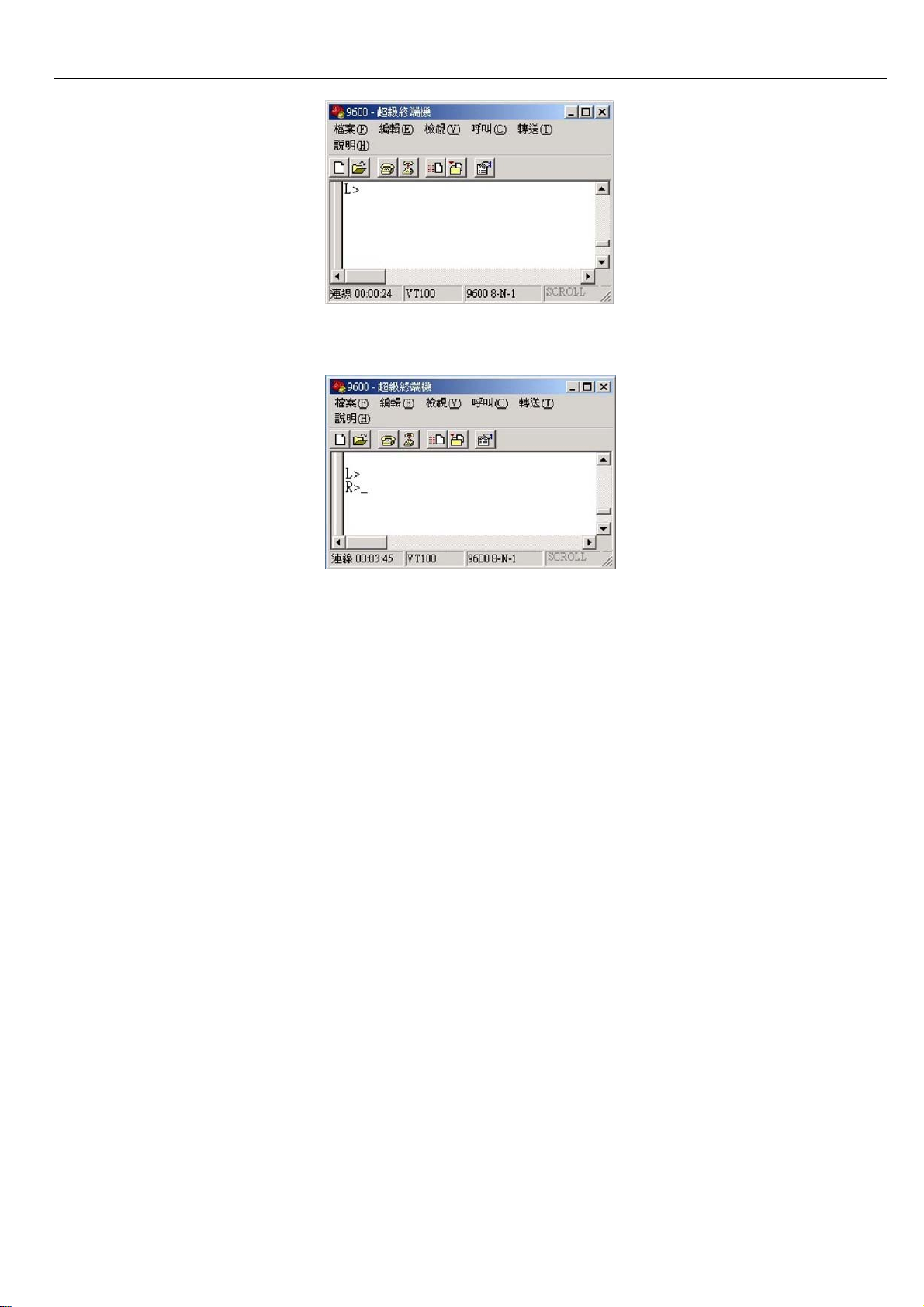
2) Connect computer and VDSL CO Modem Smart Console ports3) Run “Hyper-terminal”
program into terminal window:
3) Set “Bits per second” at 9600 to the content window. Set “Flow control” at None
4) You can see Hyper-terminal command line by “L>” it means local modem- VDSL CO
Modem Smart
- 29 -
Page 30
XtendLan VC102MB – User’s Guide http://www.xtendlan.com
5) Type “CTRL-E” and then command line will become “R>” it means remote modem- VDSL
CPE Modem
6) Type following command to Enable VDSL CPE Modem LWD and change LWD timer
R>WR 8D00 B4
R>WR C255 01
R>WR C052 B8
R>WR C053 0B
R>WR 8D00 0
7) Type following command to check register of VDSL CPE Modem
R>RD C255
C255 : 01
R>RD C052
C255 : B8
R>RD C053
C255 : 0B
8) Power off and then power on VDSL CPE Modem
- 30 -
Page 31

XtendLan VC102MB – User’s Guide http://www.xtendlan.com
Power and Cooling Problems
If the POWER indicator does not turn on when the power cord is plugged in, you may
have a problem with the power outlet, power cord, or internal power supply as explained
in the previous section. However, if the unit power is off after running for a while, check
for loose power connections, power losses or surges at the power outlet, and verify that
the fan on back of the unit is unobstructed and running prior to shutdown. If you still
cannot isolate the problem, then the internal power supply may be defective. In this case,
contact your dealer.
Installation
Verify that all system components have been properly installed. If one or more
components appear to be malfunctioning (e.g., the power cord or network cabling), test
them in an alternate environment where you are sure that all the other components are
functioning properly.
Transmission Mode
The default method of selecting the transmission mode for RJ-45 ports is 10/100 Mbps
ETHERNET, for RJ-11 port are 10Mbps VDSL. Therefore, if the Link signal is disrupted
(e.g., by unplugging the network cable and plugging it back in again, or by resetting the
power), the port will try to reestablish communications with the attached device via
auto-negotiation.
If auto-negotiation fails, then communications are set to half duplex by default. Based on this
type of industry-standard connection policy, if
you are using a full-duplex device that does
not support auto-negotiation, communications can be easily lost (i.e., reset to the wrong
mode) whenever the attached device is reset or experiences a power fluctuation. The
best way to resolve this problem is to upgrade these devices to a version that support
Ethernet and VDSL.
Physical Configuration
If problems occur after altering the network configuration, restore the original
connections, and try to track the problem down by implementing the new changes, one
step at a time. Ensure that cable distances and other physical aspects of the installation
do not exceed recommendations.
System Integrity
As a last resort verify the switch integrity with a power-on reset. Turn the power to the
switch off and then on several times. If the problem still persists and you have
- 31 -
Page 32

XtendLan VC102MB – User’s Guide http://www.xtendlan.com
completed all the preceding diagnoses, then contact your dealer.
- 32 -
Page 33
XtendLan VC102MB – User’s Guide http://www.xtendlan.com
10.2 Speed change quick guide
Please follow the procedures below step by step to change the speed settings of
VDSL CO & VDSL CPE:
1. Power on both VDSL CO & VDSL CPE
2. Connect each others over phone wire (PLEASE USE ENCLOSED PHONE WIRE)
Note: Please remove PBX(voice)signal when running speed change function.
3. Wait for a while and check if both link LEDs are on.(Default on 10M mode)
4. Plug in one end of the console cable(RJ-45) to VDSL CO then connect the other
end(RS-232) to PC/Laptop’s RS-232 COM port. Please select which COM port you
have connected & click OK.
5. Insert the diskette and select the VDSL Configuration Software
6. Run speed change utility program with Microsoft Win95/98/2000/NT/XP OS
Double click on the VDSL Configuration Software Icon, you will see
7.
8.
You will now see
- 33 -
Page 34
XtendLan VC102MB – User’s Guide http://www.xtendlan.com
9. Click Link Configuration to enter
10. Select speed mode according to your requirement. Speed mode=Line Rate.
11. Check phone wire length limitation:
4/1M 1900 meters = 6270 feet
5M 1500 meters = 4950 feet
10M 1200 meters = 3960 feet(default)
15M 1000 meters = 3300 feet
12. Click “Apply” to confirm settings
13. VDSL CO & CPE’s LEDs will be off
14. Wait for around 1 minut
- 34 -
Page 35

XtendLan VC102MB – User’s Guide http://www.xtendlan.com
15. Check if the LEDs of both VDSL CO &
16. If yes, the speed change is done successfully ,VDSL CPE are on
Troubleshooting:
How to fix if VDSL CO & VDSL CPE cannot link, which caused by speed change
failure?
1. Re-connect both VDSL CO & VDSL CPE by short length phone wire and without
PBX(voice) signal
2. Re-power on VDSL CPE once
3. Change VDSL CO to its last speed mode
4. Wait for about 1 minute
5. Check if both LEDs of VDSL CO & VDSL CPE are on
6. Done
If you forgot the last speed mode of VDSL CO:
Please try to change the from 4/1M to 15M until both link LEDs are on
Note : Please wait for 1 minute after running the speed change program to re-establish link.
- 35 -
Page 36

XtendLan VC102MB – User’s Guide http://www.xtendlan.com
11 Compliance and Safety Information
FCC Radio Frequency Interference Statement
This equipment has been tested and found to comply with the limits for a computing device,
pursuant to Part 15 of FCC rules. These limits are designed to provide reasonable
protection against harmful interference when the equipment is operated in a commercial
environment. This equipment generates, uses and can radiate radio frequency energy and,
if not installed and used in accordance with the instructions, may cause harmful
interference to radio communications. However, there is no guarantee that interference will
not occur in a particular installation. If this equipment does cause harmful interference to
radio or television reception, which can be determined by turning the equipment off and on,
the user is encouraged to try to correct the interference by one or more of the following
measures:
1 Reorient or relocate the receiving antenna.
2 Increase the separation between the equipment and receiver.
3 The equipment and the receiver should be connected to outlets on separate circuits.
4 Consult the dealer or an experienced radio/television technician for help.
Changes or modifications not expressly approved by the party responsible for compliance
could void the user’s authority to operate the equipment. If this telephone equipment causes
harm to the telephone network, the telephone company will notify you in advance that
temporary discontinuance of service may be required. But if advance notice isn’t practical,
the telephone company will notify the customer as soon as possible. Also, you will be
advised of your right to file a complaint with the FCC if you believe it is necessary.
The telephone company may make changes in its facilities, equipment, operations or
procedures that could affect the proper functioning of your equipment. If they do, you will be
notified in advance in order for you to make necessary modifications to maintain
uninterrupted service.
This equipment may not be used on coin service provided by the telephone company.
Connection to party lines is subject to state tariffs.
Important Safety Instructions
Caution:The direct plug-in wall transformer serves as the main disconnect for the product. The
socket outlet shall be installed near the product and be readily accessible.
Caution:Use only the power supply included with this product.
In the event the power supply is lost or damaged:
- 36 -
Page 37

XtendLan VC102MB – User’s Guide http://www.xtendlan.com
¾ In the United States, use only with CSA certified or UL listed Class 2 power supply, rated
5VDC 1A or above.
¾ In Europe, use only with CE certified power supply, rated 5Vdc 1A or above.
Do not use this equipment near water, for example in a wet basement.
Avoid using a telephone during an electrical storm. There may be a remote risk of electrical shock
from lightning.
Do not use the telephone to report a gas leak in the vicinity of the leak.
If trouble is experienced with this unit, please contact customer service at the address and
phone listed below. Do not disassemble this equipment. It does not contain any user
serviceable components.
FCC Warning
This equipment has been tested and found to comply with the limits for a Class A digital device,
pursuant to Part 15 of the FCC Rules. These limits are designed to provide reasonable protection
against harmful interference when the equipment is operated in a commercial environment. This
equipment generates, uses, and can radiate radio frequency energy and, if not installed and used in
accordance with the instruction manual, may cause harmful interference to radio communications.
Operation of this equipment in a residential area is likely to cause harmful interference in which case
the user will be required to correct the interference at his own expense.
CE Mark Warning
This is a CE class A product. In a domestic environment, this product may cause radio interference
in which case the user may be required to take adequate measures.
Warranty
The original owner that the product delivered in this package will be free from defects in material and
workmanship for one year parts after purchase. There will be a minimal charge to replace
consumable components, such as fuses, power transformers, and mechanical cooling devices. The
warranty will not apply to any products which have been subjected to any misuse, neglect or
accidental damage, or which contain defects which are in any way attributable to improper
installation or to alteration or repairs made or performed by any person not under control of the
original owner.
The above warranty is in lieu of any other warranty, whether express, implied, or statutory,
including but not limited to any warranty of merchantability, fitness for a particular purpose,
or any warranty arising out of any proposal, specification, or sample. Shall not be liable for
incidental or consequential damages. We neither assumes nor authorizes any person to
- 37 -
Page 38

XtendLan VC102MB – User’s Guide http://www.xtendlan.com
assume for it any other liability.
Note: Please do not tear off or remove the warranty sticker as shown, otherwise the warranty will be
void.
- 38 -
 Loading...