


XL-ICA-661M1CP
NETWORK PAN/TILT DOME CAMERA USER MANUAL

2

3
Contents
Intr
oduction
Safety Cautions
<Chapter 1. Package>
1.1 Camera Features
·······························································································
9
1.2 Pa
1.3 How To
ckage
1.3.1 Camera installation
1.3.2 Dimension····································································································
1.3.3 Reset Button & Factory Reset switch···································································
3
·
···········································································································
Install
Camera Specifica
Camera Function·····························································································
Network Specifica
Electric Specification
Alarm Input/
································································································
·····················································································
··································································································
tion
························································································
tion
························································································
························································································
Output
···························································································
<Chapter 2. Installation and Video Check>
2.1
Installatio
2.2 Video Che
1
Change the setting value of PC network environment
n
·······································································································
ck
····································································································
·················································
9
10
10
11
11
16
17
Connect the camera with web
See the video··································································································
2.2.4 Input ID/Passw
2.2.5 Ac
2.2.6 Complete the
2.2.7 NetViewer descr
tive-X auto
ord
··························································································
instal
lation·················································································
installat
ion
iption······················································································
browser
··················································································
···································································
<Chapter 3. Network Setting>
3.1 Check Network and Installation Type
3.2 Installation without IP sharing de
3.2.1 Static IP Setup·································································································
3.2.2 Dynamic IP Setup·····························································································
3.3 Installation with IP sharing de
General Installat
ion
···························································································
vice(router)
·······························································
vice(route
r)
·····················································
··························································
19
19
21
22
24
24
24
29
31

4
<Chapter 4. System Setting>
4.1 General Setti
4.1.1 Title Setting
4.1.2 Time Setting
4.1.3 Ac
4.1.4 Select Language····························································································
tive-X download
ng
································································································
··································································································
·································································································
·························································································
35
36
36
37
37
4.2 Access Setting
4.2.1 Administrator's ID and Password Cha
4.2.2 User Registration
4.2.3 User List······································································································
4.3 Network Setting
4.4 Stream Port Setti
4.4.1 TCP/IP
4.4.2 RTSP···········································································································
4.4.3 HTTP/
CGI
4.5 Video Setting
4.5.1 Video format
4.5.2 Resolution
4.5.3 Video Mirror Function······················································································
4.6 MPEG Setting
4.6.1 MPEG4 stream service
4.6.2 Stream Setting
4.7 MJPEG Setting
4.7.1 MJPEG Stream Service····················································································
4.7.2 Stream Setting
·································································································
nge
······························································
···························································································
·······························································································
ng
··························································································
·········································································································
·····································································································
···································································································
·································································································
····································································································
··································································································
·····················································································
·······························································································
·································································································
·······························································································
38
38
39
39
39
40
40
41
41
42
42
42
42
43
43
43
45
45
45
4.8
Preset/Motion Setting
4.8.1 Preset/Motion Setting
4.8.2 Motion detect fu
4.9 OSD Setting
4.9.1 OSD Fu
4.9.2 OSD Type····································································································
4.9.3 OSD Font·····································································································
4.9.4 OSD Color····································································································
·····································································································
nction
································································································
4.10 Camera Control
4.10.1 Display Adjustment······················································································
4.10.2 White
4.10.3 Back Light Compensation
Balance······························································································
4.11 Camera Control
4.11.1 Effect 1
······································································································
······················································································
·····················································································
nction
····················································································
1
···························································································
···············································································
2
···························································································
46
47
47
48
48
48
49
49
50
50
50
51
51
51

5
4.11.2 Effect 2
4.11.3 Electronic Shutter Speed
······································································································
················································································
51
52
4.12 Alarm In/Out Setting
4.12.1 Alarm In
4.12.2 Alarm Out
···································································································
···································································································
4.13 Alarm Recording Setti
4.13.1 Recording Function·······················································································
4.13.2 Recording Interlock
4.13.3 Server
·······································································································
4.14 Auto Action Setting
4.1
4 . 1 P O A
4. 1 4.2 Aut o Run
·······················································································
············· ····· ······ ··· ············· ······ ············· ··················· ··· ··
4.15 Homepage Update
4.16 Firmware Upgrad
·······················································································
ng
···············································································
ing
···················································································
···············································································
·························································································
e
··························································································
<Chapter 5. IP>
Use of IP
Run IP finder program
finde
r
·····························································································
···················································································
53
53
54
55
55
55
55
55
56
56
57
58
Find IP address
Change IP addr
··························································································
ess
······················································································
<Chapter 6. Basic Network>
6.1 Public IP
6.2 Private
6.3 Ping test
··································································································
IP
·········································································································
········································································································
<Chapter 7. Appendix>
7.1 Basic setting table
7.2 Troubleshooting of cable
7.2.1 Power cable connection check
7.2.2 Network cable(LAN Cable) connection check
7.3 Troubleshooting of Network connection·················································
7.3.1 Cannot connect with Netw
7.3.2 Check port setting
···························································································
connection
················································
···························································
··············································
ork
·······························································
··········································································
68
69
70
73
74
74
74
75
75
75

6
<Chapter 8. Troubleshooting>
···········································
76

7
Introduction
This is a megapixel network camera which uses a 1/3-inc
HAD CCD
Bu
ilt-in MPEG4, MPEG CODEC and streaming server, the advantage of this camera allow you
h megapixel progressive scan SONY Exview
to
monitor real time image from a remote location via internet. This camera supports both static IP
dynamic IP, and can change
servers. It also supports CMS(Central Monitoring System), various services and features
for outdoor use without extra device.
communication
port, resulting in one IP address supporting mu
weat
<Cau
tion>
Software, server and service may be charged according to change of policy or may be
stopped without prior
without prior
notification.
resulted from changes in policy or products.
notification.
Appearance, function and
specification
may be change
Our company assumes no responsibility for visible or invisible loss
d
Safety Cautions
*This
camera may be damaged by electrical and physical shock.
Use regulated 12V DC, 1A power supply. Do not throw or drop it onto floor.
*In
case the unit fails, DO NOT try to disassemble the
product.
Contact or consult the distributor or an authorized technician for after-sales service.
and
ltip
le
herproo
f
Warranty void for the product disassembled without an authorization from the distributor
an authorized
*
All responsibility by using this unit is on the user.
*In
case it is installed at high location, be sure to mount securely to prevent the unit
technician.
falling below
fro
or
m

8
Chapter 1.
Pac
1.1 Camera Features
1.2 Package
1.3 How To
kage
Specificatio
··········································································································
Install
n
··································································································
······························································································
·································································································
10
9
9

9
Chapter 1. Package
1.1 Camera Features
1) The built-in 3.6X optical zoom and up to 30 preset can be set.
2) Firmware upgrading and function controlling are available by
3) Bu
ilt-in 1.3 Mega pixel 1/3" progressive Sony EXview HAD CCD.
4) This camera has Sense up function to receive the maximum availablet night.
5) Equipped with a number of convenient new functions such as OSD, Motion detection and E-
zoom
network.
6) This camera adopted PoE that supplies power in addition to data sending and rec
using LAN cable without separate power
users at
When you connect the camera with PoE and DC adaptor, Only PoE is used.
installation.
connection
and it provides convenience for
eiv
ing
1.2 Package
Package of Products is composed of camera, screw, user manual, software CD, cross cable(see
below). Please check before starting installation. If there are any missing, please contact the sh
where you purchased. The cross cable should be used only for
change of network informa
[Cau
tion] Please see the package as follows. This manual is based on Microsoft Windows XP. So, there
would be the Difference according to operating syst
tion.
em
pre-v
iew
of video before
set-up a
op
nd

10
1.3 HOW TO INSTALL
1.3.1 Camera
Fix the camera set with the supplied screws on ceiling m
If you
Put a sticker on the ceiling and make holes according to the spots marked on a sticker.
installation
don't
use supplied screws, the camera may fall off.
oun
t.
<Ceiling mount>

11
1.3.2 Dimension
1.3.3 Reset Button & Factory Reset switch

12
1.4 Specification
I
tem
Specificati
on
Type
Megapixel network PTZ dome camera
Image Sensor
1/3” SONY Progressive Scan
EXview
HAD CCD (1.3 Mega
Pix
els)
Effective pixel
1296 (H) × 966 (V)
Cell size
3.75㎛(H) x 3.75㎛(V)
Resoluti
on
1280 x 960 / 640 x 480 / 320 x 240
TV Ty
pe
NTSC / PAL
Scanning Sy
stem
Progressive Scan
M
in.il
lum
inat
ion
0.01 Lux (Sense up Auto x 4
)
Alarm
input/outpu
t
Input:1,output:1
Lens
Focus free zoom – Auto iris lens(f=2.8~
10mm
)
I
tem
Configuration
BLC
Off, BLC1, BLC2, BLC3
Sense u
p
X1 ~ X255
Brightness
A
djustable
Contras
t
A
djustable
Sharpness
A
djustable
AWB
Auto, Indoor, Outdoor, Fluorescent, Manua
l
Satura
tion
A
djustable
Hue
A
djustable
Nega
tiv
e
Off, On
Pattern Generator
Off, On
Focus
inde
x
Display Off, On
Blemish
Dynamic Compensation
EZOOM
X1 ~ X12 Selectable
1.4.1 Camera Specificatio
n
1.4.2 Camera Function

13
1.4.3 Network Specification
Classificati
on
I
tem
Specificati
on
Summary
OS
Embedded Linux
Network Interfac
e
RJ45 10/100BaseT,
Ethernet
S
etting
By web
browser
Network su
pport
Leased Line, Cable Modem, Support Dynamic IP
and Static IP. ADSL usable under Router
Supported Protocol
HTTP,FTP,TCP/IP, DHCP, ARP, DNS, ICMP, RTSP
Security
USER
AUTHENTICATION
PC OS(Viewer)
WINDOWS
XP,
WINDOWS
VISTA,
WINDOWS
7
Web
brows
er
Server setting function, Web Viewer
Download Page, User Homepage Upload
Image
C
ompress
ion
MPEG-4,
MJPEG
Resoluti
on
CIF(320x
240)/VGA(640x
480)/QVGA
(1280x
960)
Compression Rate
200:1(Typical)
Frame Rate
NTSC ( MAX :CIF/VGA
30 fps, QVGA 15 fps )
PAL (
MAX:CIF/VGA
25 fps, QVGA 12.5 fps)
Bit Rate
64kbps ~ 8000kbp
s
Function
Simu
ltaneous
Access
Max. 10 users(under 5 users recomm
ended
)
Video Recording
Recording in client PC with CMS or
FTP Server upon Alarm Event
Motion De
tec
tio
n
Support
OSD
Support
Alarm Input/Output
Support
Dynamic IP
Support
IP Router
Support
DDNS
Support

14
1.4.4 Electric Specificatio
Classificati
on
Specificati
on
Power Supply
Regulated 12V DC
PoE(Power over Ether
net)
Current Consum
ptio
n
MAX. 1A(DC 12V)
Operation Tem
p.
5℃ ~ 50
℃
Preservation Tem
p.
-20℃ ~ 60℃
Dimension
Ø150X
136.4(H)m
m
W
eight
Approx.
1.2Kg
※The
specification
1.4.5 Alarm Input/Output
n
is subject to change without any prior notice to improve the qua
lity.

15
Chapter 2.
Installation and Video Check
2.1
Installatio
2.2 Video Che
n
······································································································
ck
····································································································
16
17

16
Chapter 2. Installation and Video Check
2.1 In
On the assumption that User PC and the camera are used under static IP,
sta
llation
and the camera is to be directly connected with User PC or Local
The installation procedure is to
(1) Connect the camera and PC with LAN Cable(Cross ca
(Please use the direct cable if you connect to local
(2) Power on camera.
*
Using regulated 12V DC 1A
*
Using PoE(Power Over Ethernet) : This camera adopted PoE that supplies power in addit
to data sending and receiving using LAN cable without separate power
provides convenience for users at
When you connect the camera with PoE and DC adaptor, Only PoE is use
(3) Wait about 2 minute after on camera, the system will be
be;
ble).
network)
installation.
Network,
connection
d.
booted.
and
ion
it

17
2.2 Video Check
Basic network setting value of the unit is to
be;
To connect the unit in user's
Set IP Address, Subnet Mask and Gate-way
255.255.255.0 / 192.168.1.1 as shown on [Pic. 2-1].
[Cau
tion] Before changing the setting value, please memorize the previous setting value
on your PC.
PC, change the setting value of PC network environment.
of user's
PC with 192.168.1.50 /
2.2.1 Change the setting value of PC network enviro
nment
[Pic. 2-1]
Network Setting for User PC

18
2.2.2 Connect the camera with web
brows
er
[
Pic. 2-2] Web Browser Address Input
(1) Run web browser as shown [Pic. 2-2].
(2) Input 192.168.1.8 (default value) in URL and press
(3) And then, [Pic. 2-3] is to be shown.
"ENTER" button.
[
Pic. 2-3] Main H
omepage
(4) In case [Pic. 2-3] does not appear, press "factory reset" button for 5sec to reset
Hardware.
(5) Shown [Pic. 2-3],
installation is comp
lete

19
2.2.3 See the video
Click button on the main page [Pic. 2-3].
2.2.4 Input ID/Password
Input ID and Password and click on to see the video feed
(ID : root, Password : root)
[
Pic. 2-4] User Lo
gin
User's Authority to see video feed is as follow
[Table]
User ID, Password, Au
[Cau
tion] Please change default value of ID/Password into new ones after the
2.2.5 Ac
Input ID and Password and click on to see the video fee
User's
tive-X auto
Authority to see video feed is as follow
installation
d.
thority
installation
Click "install" on the security certificate to load the Ac
"Don't install", the web viewer would not
work.
tive-X control. If you choose

20
[
Pic. 2-5] ActiveX
Download

21
2.2.6 Complete the
installation
Upon installation, Web Viewer [Pic. 2-6] appears and image of camera is to be seen.
[
Pic. 2-6] Web
Installation and check video are completed successfully
Please change ID/PASSWORD.
View
.
er

22
2.2.8 Net Viewer descr
Image of viewer size is fixed as 640 * 480.
iption
① Selection of streams(MPEG4, MJPEG) Default value is MPEG4
② Run preset of desired preset number or sequence action
(In case of the Sequence, "Preset No" means group number.)
③ Run
RELAY
action of desired
number
④ Press the direction key to move the camera.
⑤ Press the home button to move the Home
⑥ Setting camera's speed
preset
⑦ Control the camera's zoom
⑧ Press the Auto Pan button to rotate the camera without
limit.
⑨ Connect to server/ Disconnect
⑩ Go to Administrator's
page
⑪ Display the current time
⑫ Start recording
⑬ Stop rec
ording
⑭ Select location to save
⑮ Capture still image into BMP file

23
Chapter 3.
Network Setting
3.1 Check Network and Installation Type
3.2 Installation without IP sharing de
3.3 Installation with IP sharing de
vice(Router)
vice(Rou
·····················································24
···········································
ter)···············································
24
31

24
Chapter 3. Network Setting
3.1 Check Network and Installation Typ
This Chapter is for basic setting regarding Network. To install hardwar
e
e,
basic understanding of network is required.
[Warning] The setting value might be different in accordance with network environment of user's PC.
[Ref
erence]
Please refer to Appendix for better under
standing.
There are two ways to install hardware.
1. Install the camera without IP sharing device.
2. Install the camera under IP sharing device which is required PPPoE environ
ment
This explanation is based on upon default value of ex-fac
[Cau
tion 1] Check video before installation, on 'Chapter 2.Installation and video check'.
[Cau
tion 2] In case using IP sharing device, only global IP is ava
tory.
ila
ble.
[Cau
tion 3] This unit doesn't support PPPoE directly. So, IP sharing Device is required
connect to the camera.
<Installation without IP sharing device>
ㆍFor static IP, refer to '3.2.1 Static IP Setup'.
ㆍFor dynamic IP, refer to '3.2.2 Dynamic IP Setup'.
<Installation with IP sharing device>
ㆍShould set up with Static IP, refer to '3.3 Installation with IP sharing device' .
3.2 Installation without IP sharing device(router)
3.2.1 Static IP Setup
(1) Connect the camera to PC with LAN cable(cross ca
(2) Cable
connection
'Chapter 2. Installatio
(3) Connect the camera to Web.
and network setup should be same as in
n and video check'’
Run web browser and input http://192.168.1.8(default
ble).
value) in URL
and
to
press
"ENTER"
button then [Pic. 3-1] will be shown.

25
(4) Administration page log-in
[
Pic. 3-1] Main Page
Click on [Pic. 3-1],
After inputting 'admin' in ID and Password
then browser shows [Pic. 3-2]
[
Pic. 3-2] Administration page login
line.
Click button then [Pic. 3-3] Administrator's page will be shown.
log-in Page
.

26
[Cau
tion] If you logged in first in administrator mode, please change the password and
ID of a
Please refer to 4.2.1 Administrator's
dministrator.
ID and password cha
nge.
[
Pic. 3-3] Administrator's Page
<Caution> If your browser block Pop-up, click right mouse button and change the option to 'always
allow
pop-up from this site'.

27
(5) Network Setting
Click 'Netw
ork S
etting' on [Pic. 3-3], [Pic. 3-4] appears.
[
Pic. 3-4] Network Setting
(6) DNS Server Setting
For setting of DNS server, input DNS address to fit with network environment to set(Default addr
is DNS address of 'KT Telecom').
Use DNS value normally set in PC. DNS address should be necessarily input. Clic
button to save setting value.
ess
k

28
(7) IP address setting
Click 'Static
IP Address' in 'IP S
etting' of [Pic. 3-4],
and input IP Address
,
Subnet Mask, Default Gateway according to network environment.
Click button to save setting value. Click 'C
[
Pic. 3-5]
connected.(May
has been change
As IP Change loading page appears as [Pic. 3-6],
not find the main page of changed address under cross cable
d.)
lick Here' upon appearing of IP change window of
[
Pic. 3-5] IP change
the main page of changed address
connection,
but IP
is
[
Pic. 3-6] IP Change loading
page
(8) Remove LAN Cable(cross cable) connected between the camera and PC.
(9) Connect the camera to network with LAN cable(Direct ca
(10) Connect PC to network with LAN cable(Direct ca
ble).
(11) Set up IP address, Subnet Mask and Gate way of PC according to
environment(Recommended
user's
PC setting).
to user to remember the value before changing
ble).
network

29
(12) Check
Run web browser on PC, input IP address set in the unit onto URL
and
click as [Pic. 3-7].
When main page appears as [Pic. 3-1],
check if IP setting is correct or not.
(Refer to'Chapter 2. Installation and video check')
In case video is not seen, check whether there may be
click button to connect to web viewer
confliction
of IP in network, and rechec
the set value of network environment of the camera, and network environment of User's PC.
[
Pic. 3-7] Connect to the u
nit
(13) DDNS Setting
and
k
1. Please check the checkbox for use
2. Please enter an user e-mail address.
3. Please enter the server address.
4. Please enter the
( Default port is “9202“ )
5. Please enter the user domain name.
DDNS
6. You should check your domain name before registra
7.
Save
[Ref
erence]
If you register on DDNS server we operate, you can use the registered
domain name for connec
3.2.2 Dynamic IP Setup
Do not set up dynamic IP in the unit except directly
current value
tion.
.
DDNS function.
(Default address is "ipcctvlink.com"
service por
t.
connecting
)
tion.
the camera to network su
pporting
dynamic IP. If the IP has not been allocated to the unit in dynamic IP setting, please press the
'FAC
TORY RESET
BUTTON' for 3 sec(refer to the page of 13) then try to setup a
gain.

30
(1) Connect the unit and PC with LAN cable(cross ca
(2) Cable
'Cha
(3) Go to network setting page of
'Sta
connection
and network setting should be done same as
pter 2. Installation and video check' and check video.
administrator's
tic
IP Setup'
※If you using dynamic IP you should setup the DDNS.
ble).
page as per
(3),(4),(5) of
[
Pic. 3-8] Network Setting
(4) DNS server setting
For setting of DNS Server, input DNS address to fit with network environment to set(Default address is
DNS address of 'KT Telecom'
).
Use DNS value normally set in PC.
DNS address should be necessarily
input.
Click button to save setting value.
(5)
Dynamic IP address

31
Click on 'Dy
namic IP Address' in 'IP S
etting'.
Click button to save, and [Pic. 3-9] will be shown.
[
Pic. 3-9] Dynamic IP Setting
(6) Remove LAN cable(cross cable) connected between the camera and PC.
(7) Connect the camera to network with lan cable(direct ca
(8) Connect PC to Network with LAN cable(direct ca
ble).
ble).
(9) Set up IP address, Subnet Mask and Gate way of PC according to network environment.
(10) Installation Check
If you will connect provided internet line from ISP(Internet service provider) to unit directly :
Connection of XL-ICA-661M1CP by DDNS
[Reference] Please refer to page 29 '12) DDNS
ex) If you regeisted domain name is "mycam", your web site is
For the regeiseter the doamin name, it takes 5minute. Please wait for a
setting'
"mycam.ipcctvlink.com"
while.
If you have the DHCP server to assign an IP Address :
First close the web browser, you can find out the IP address using program of "IP Finder" in
installation CD (Please refer to "5.1 Use of IP finder")
If you found the assigned IP to unit rightly, open the web browser, input IP address of the camera
then press the
"ENTER"
key. The main page will be shown as [Pic. 3-1]
If you couldn't find the unit, it means IP has not been allocated to the unit so you have to press the
'FACTORY RESET BUTTON' for 3 sec then try to aga
If you turn off the camera and reactivating in dynamic IP environment, might be change the IP
in.
address.
So if you register the IP address to DDNS server, you can use the domain name

32
3.3 Installation with IP sharing device(router)
3.3.1 General Installation
(1) Connect the camera and PC with LAN cable(cross ca
(2) After checking video in '2. Installation and video check',
ble).
then go to the next step.
(3) Go to network setting page of Administrator's Page as per 3), 4), 5) of '3.2.1 Static IP Setup'
[
Pic. 3-10] Network Setting
(4) DNS Server Setting
For setting of 'DNS server', input DNS address to fit with network environment to set.
(Default address is DNS address of 'KT T
Use DNS value normally set in PC. Click button to save the setting valu
(5) IP Address Setting
Click 'Static
Gateway(Please refer to the manual of IP sharing device) and click button to save the setting valu
Click button to save the setting value.
IP Address' in 'IP S
elecom')
e.
etting' of [Pic. 3-10],
and input IP Address, Subnet Mask,
Default
e.

33
When [Pic. 3-11] appears, click 'C
lick Here' to go to the changed main page.
(In case of
comp
leted)
connecting
with cross cable, may not found the changed page but IP change has bee
[
Pic. 3-11] IP change
(6) Connect the camera to IP sharing device with LAN cable(direct cable
(7) Connect PC to IP sharing device with LAN cable(direct ca
ble).
n
).

34
Chapter 4.
System Setting
4.1 General Setting
4.2 Access
4.3 Network Setting
4.4 Stream Port Setti
4.5 Video
4.6 MPEG
4.7 MJPEG
Setting
Setting
Setting
Setting
························· ·······················································
·· · ·········· · ········ ········ · · ········· · ········· · ······· · · ········ · ········· ··
······························································· ·················
ng
·······················································································
········ ······· ······· ··········· ··········································· ········
·· ········· · ········ · · ·········· ········ · · ······· · ·········· ········ ········ · · ·····
·· ··········· · ··········· · ·· ······· · · ··········· · · · ········· · ··········· · ········
4.8 Preset/Motion Setting
4.9 OSD
4.10 Camera
4.11 Camera Control
Setting
Control1
········· · ·········· ······· · · ········ · ················· · · ········ ·················· · ·
···· · ··········· · ············ · ··········· · ········· · ··········· · · ···········
2
4.12 Alarm In/Out Setting
4.13 Recording Functio
4.14 Auto Action Setting
4.15 Homepage Updat
e
4.16 Firmware Upgrade
··
··················································································
··················· ························································
···· · ········· · · ······· · · · ········· ·········· · ·········· · ········· · · ···
n
········································································
········································································
··············· ······· ········· ····································· ···· ·
··········································································
35
38
39
40
42
43
45
46
48
50
51
53
55
56
57
58

35
Chapter 4. System Setting
Click on main home Page, login page [Pic. 4-1] appears.
Input 'admin', 'adm
page
will be shown.
[Ref
erence]
<Caution> Change ID and Password of Administrator in General Setting of '4.2 Access Set
ID and Password are preset as admin / admin in Administrator's Page.
in'
in ID and Password line, click then [Pic. 4-2] Administrator's
4.1 General Settin
g
[
Pic. 4-1] Administrator's page
login
tin
g'
[
Pic. 4-2] General Setting

36
[
Pic. 4-3] Title Setting
Server title would be shown on the top of the video when you see the video by the viewer. Server
is to be English without space(Max. 10 characters).
title
Click
' '
button to save title after inputting nam
e.
4.1.2 Time setting
There are two ways of time setting as follow.
'Au
tomatic S
Select one of time zone in 'Set Time Zone' and save
'
User Setting' : This is for user to set up time directly. There can be some gaps between local a
time of the unit.
'DST
setting' : Set up the
month/week/day/time” after
setting period.
Caution: The time is changed to default time when the camera reboot.
etting':
This is to set up local time in case of monitoring from different time zone area.
Daylight
Saving Time. Setup the “start :
checking the ‘DST setting’
box,
month/week/day/time”
it
will
be
shifted
back one hour
nd
and “ end :
duri
ng
[
Pic. 4-4] Time Zone

37
Click 'Display'
to see current time set.
[
Pic. 4-5] Current time vi
ew
If 'Automatic
(Clicking
Click 'Get PC Time' to receive time on client PC, and click
This is to set how to download Ac
case setting as local download, it has a merit to use in private network without Internet. In case
setting as download from outside, it has a merit to download the updated Ac
automa
Setting' is not correct, click
'
' button, it will receive new time information.)
tically.
'
' on [Pic. 4-4] a
gain.
' '
button to save.
tive-X of web viewer, locally or from outer server designated. In
tive-X of web viewer
[
Pic. 4-6] Ac
tive-X plug-in download route
of
This is to select language to be displayed in all web pages such as Administrator's page, web view
and main
It supports both English and Korean now. Click
language
page.
[
Pic. 4-7] Select Language
'
' button to save the set value after select the
er

38
4.2 Access Setting
[
Pic. 4-8] Access setting
<Caution> Change Administrator's
to
others.
[
Administrator's ID and password should be English, within 20 characters, without space.
Click
' '
cas
e of forgetting Administrator's ID and password, click 'Fac
button to save the changed value after changing Administrator's ID and password. In
Pic. 4-9] Administrator's ID and password change
ID and password and do not disclose the information
tory
Set' button for 3 sec to return to
initial value, and change Administrator's ID
39
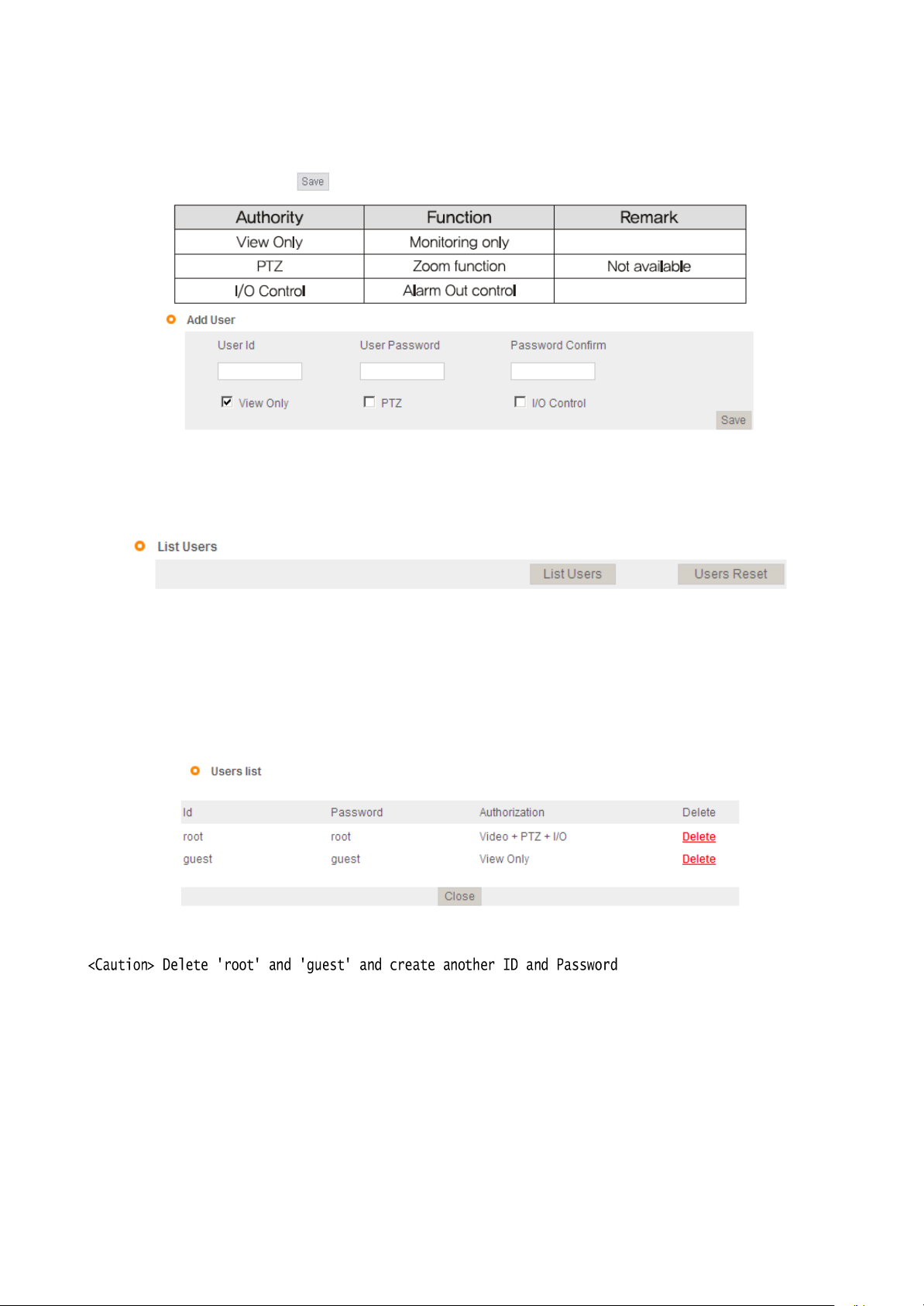
4.2.2 User Registration
This is to register an account of user who monitors and controls video.
Administrator's ID and Password should be English, within 20 characters, without space. Allow the
authority to users and click
' '
button. A maximum user to allow registration is 100 persons.
[
Pic. 4-10] User registrat
4.2.3 User List
User list is available on clicking 'List Users'
ion
[
Pic. 4-11] User
list
to check list and delete user ID.
User ID 'guest', 'root' has be
In case of clicking 'Users Reset', basic user
pre-r
egistered as basic user ID on ex-fac
ID('guest'
and 'root') will be shown without any other user
lists
[
Pic. 4-12] User
4.3 Network Setting
This is to set network. Set network to fit user's
network environment in '3. Network Setting'. Chang
list
network information to fit environment for the unit to be installed
in.
tory.
e

40
4.4 Stream Port Setting
4.4.1 TCP/IP Setting
User can choose default setting and user setting.
Using ports are stream port, remote control port and web por
The remote control port is the stream port +1.
t.
The stream port 9000, remote control port 9001, web port 80 are default value.
Click
'
' button to save.
<Reference> If you use several cameras through the port forwarding, you should assign different
number to each camera..
port

Click '
'
button to save.
41
4.4.2
RTSP Setti
ong
This camera provides the RTSP/RTP stream transmission as well as TCP/IP stream. The function is
based on
If duplicated port used in this function with the port used from other process, it will not be
w
ell.
RTSP
VLC(http://www.v
Port : Setting of
ideolan.org/)
RTSP
port.(default
media player.
port: TCP 554
workin
)
RTP Port range: Setting the port of RTCP with RTP
*
The maximum and minimum have at least 3 range
gap.
RTCP:
-
RTCP Time out enable : If the server do not receive the RTCP from Client then RTSP session will
s
topped
Use user authentication :
-
Enable : To set using for user authority on
RTSP
sess
ion
Click
'
' button to save.
MULTICAST: Multicast function transfers the data to multiple users by a single streaming transfer. It
loaded less traffic in the network than unicast. There should, however, be mu
lti-cas
ting
functions
g
be
in
all network network equipement which is in located in between streaming server(camera) and
clients.
-IP address: D Class IP address should be allocated for the multi cast.
D Class IP address is 224.0.0.1 ~ 239.255.255.254.
-Port: 40000(default port)
-Tim
e to live(TTL): TTL is reduced one by one when it is transferred each router. When it reaches to
"0" value, the router will discard the data. The TTL Value determines how far the data is delivere
Generally the value is 128.
Click
'
' button to save.
<Reference>Please refer to the manual regarding how to connect the stream server of RTSP
4.4.3 HTTP/CGI Se
This function transfer the stream(JPEG/MJPEG) by using Server Push method and can use the control
function by CGI calls.(EX. Port I/O control)
Good point of this function is using web port , so it is able to transfer the stream and control which
not affected by fire wall.
tting
d.
is

Click '
'
button to save.
42
4.5 Video Setting
[
Pic. 4-13] Video setting
Display the video type (NTSC/PA
It was fixed at the factory and it is uncha
L).
ngeable.
This is to select resolution(CIF/VGA/
MPEG and JPEG have CIF resolution when you choose CIF resolution.
In case of video resolution, selecting 'VGA', it has 'VGA'
Selecting QVGA, it has 'QVGA' resolution in JPEG and 'VGA'
QVGA).
resolution both in MPEG and in JPEG.
resolution in MPEG. In this case, there
no OSD and privacy zone function in JPEG
Video stream is dual codec which supports MPEG and JPEG at the same
[Ref
erence]QVGA
(Quadruple VGA) : 1280 X 960, VGA : 640 X 480, CIF : 320 X 240
time.
<Caution> In case of changing video format or video resolution, the program will restart,
please wait for a wh
ile.
Make a mirror image of video.(Flip, Mirror, both)
is

43
4.6 MPEG Setting
4.6.1 MPEG4 stream service
Select MPEG stream service 'Enable'
[
Pic. 4-14] MPEG4 Setting
or 'Disable'.
Set the bit rate of the video stream. In case of VBR(Variable BitRate), user can select the video quality
among three
Bitrate is changed automatically to keep the picture qua
In case of CBR(Constant BitRate), bit rate is fixed to keep the transmission
It is selectable from 64 to 8,000 Kbps.
Frame ra
options(Normal,
te.
High, Very H
igh).
lity.
speed
.

44
[Ref
erence]
2 )GOV(Group of VOP) LENGTH
In case of selecting bit rate too low, there might be the blocking effect
Set the length of VOP which is the length from I frame to next I frame when you select I/P frame.
Select the style of VOP between 'I
data will increase and cause a heavy traffic in
frame only' and 'I/P
network.
frame'. Selecting 'I
frame only', the volume of
Set the frame rate. In case of QVGA, it has Max. 15fps in NTSC and 12.5fps in PAL. In case of VGA, it
has Max. 30fps in NTSC and 25fps in PAL.
(QVGA is available on TYPE 1 only.)
This function is to skip the frame automatically to keep the picture quality setting low bit rate.
Inactivating this function, the picture quality will be lower to keep the frame ra
te.
Set the packet size transmitting the video
Click
'
' button to save.
data
.
<Caution> In case of changing MPEG setting, the program will restart,
Please wait for a wh
ile.

45
4.7 MJPEG Settin
g
Select whether JPEG stream service available or not.
[
Pic. 4-15] MJPEG Setting
Set the video picture quality in JPEG. There are from 1 to 99. Selecting 1, it supports the best pictur
quality but the volume of data will increase. On the contrary, selecting 99, the picture quality will
lowest but the volume of data will
Recommended value is between 30 and 50.
decrease.
Skip the frame by user
'0'
can not be skipped and from 1 to 29 can be skipped. This is to keep the
set
ting.
volume of data from a heavy traffic in network. But in case of skipping too many frames, picture migh
not be natural.
e
be
t
Ex) 0 : Transmission frame X : Skip
1 :
0X0X0X0X0X
2 :
0XX0XX0XX0XX
……
…
fra
me
3 : 0XXX0XXX0XXX0XXX…

46
It is to set the size of linkage in one picture of JPEG.
'0'
means it doesn't use the linkage and in
this
case, the volume of data will
Set the packet size transmitting the video
Click
' '
<Caution> In case of changing MPEG setting, the program will restart,
Please wait for a wh
button to save.
ile.
increase.
data
.
4.8
Preset/Motion Setting
[
Pic. 4-16] Preset/Motion detection setting

47
4.8.1 Preset/Motion settin
g
1 ) Use preset
checkbox defines Enable/Di
If not selected, the preset will not be working and „Sequential‟ as well
2 ) Position
Input preset number you would like to set up.
This number will be used same as motion detection function.
3 ) Name
Set a name of preset
4) Duration
Set
staying time in each position for preset when sequence is
5) Group
Set
the group
number
If you want excluding it in the group, you should input "255".
6) Home
Set
the preset position when you click the home button to move desired position
.
Home is only one available.
4.8.2 Motion detection function
1) Enbale/Disable
Determine whether use motion detection or not.
2 ) Use MD
defines Enable/Disable of individual MD function of linked action
3) Cell size
Change the cell size of block when set motion detection
4) Sensitivity
This setting enables you to adjust sensitivity of each
70~90 is recommended for normal picture
5) Select all/Deselect
Press
6 ) Action Link
the Select
You can set the function such as "None", "Preset", "Sequence" and "Auto pan”
This function will work when detected one's
※Motion Detection function can be affected on excessive sense-up.
all
all/Deselect all button to apply the block of motion detection to all of screen
sable
of individual preset
number
working
block
quality
motion
48
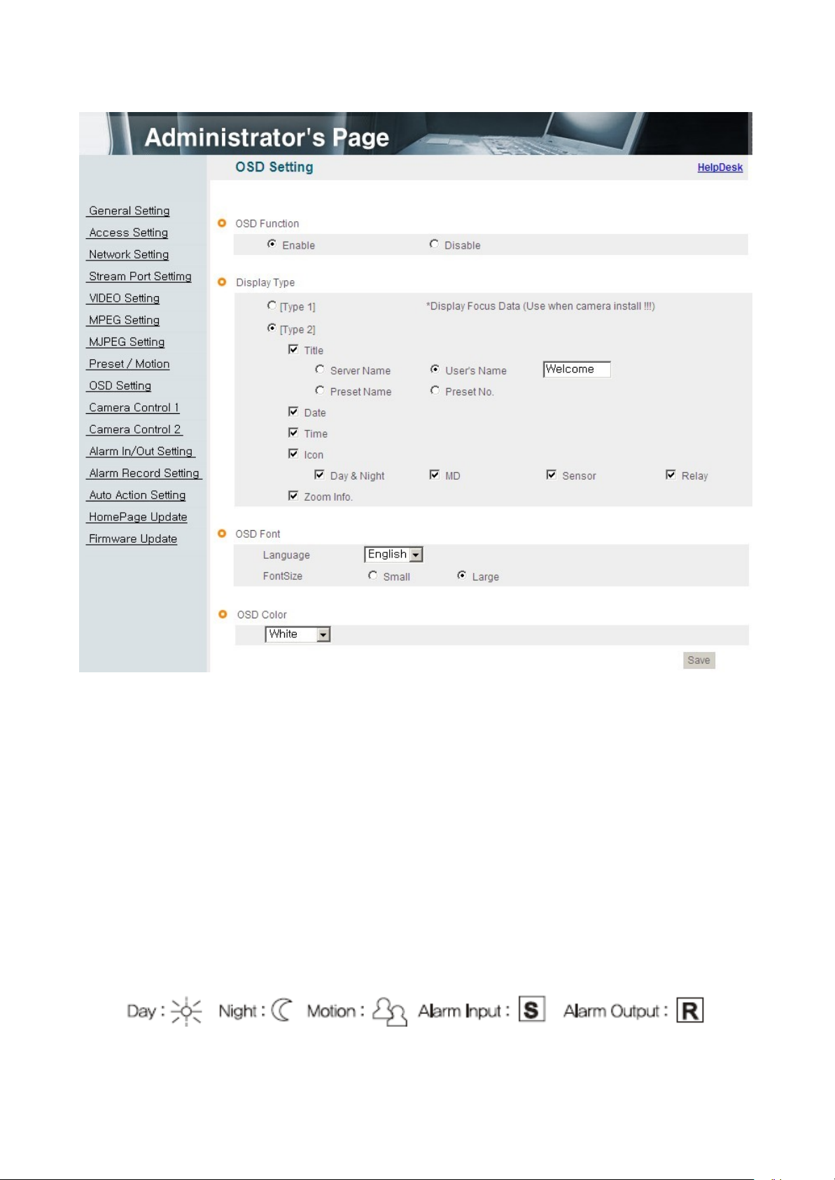
4.9 OSD Setting
4.9.1 OSD Function
Select OSD function 'E
nable'
or 'Disable'.
4.9.2 OSD Type
1) Type 1
This is to display focus data on
to adjust the focus more correctly.
2) Type 2
This is to select contents to display on
Motion, Alarm Input, Alarm
OSD.
Output).
[
Pic. 4-17] OSD Setting
Higher value means clearer image. Seeing this value, a user is able
OSD.
There are Title,
Date, Time, Zoom Info, and Icons(Day, N
ight
,

49
4.9.3 OSD Font
This is to select the language and font for OSD.
4.8.4 OSD Color
This is to select color for
Click
' '
button to save.
OSD.

50
4.10 Camera Control
1
4.10.1 Display Adjustment
Brightness : Adjust the brightness of
Contrast : Adjust the contrast of
Sharpness : Adjust the sharpness of
[Ref
erence]
As the level of sharpness increases, the screen gets sharper and the
level of noise also
Hue : Adjust the hue of picture.
Saturation : Adjust the saturation of
Click 'Default'
Click
'
to initialize the value.
' button to save
pictur
increa
[
Pic. 4-19] Camera Control 1
picture.
e.
picture.
ses.
picture.
Auto : Adjust white balance automa
tically.
Indoor : Adjust white balance to indoor environment(3200˚ K). Outdoor
:
Adjust white balance to outdoor environment(5600˚ K). Fluorescent :
Adjust white balance to fluorescent environment(4000˚ K). Manual :
Adjust white balance manually.
Click
'
' button to save.

51
4.10.3 Back Light Compensa
tion
It is used to get the best quality picture against the back
light.
BLC OFF : Not use back light compensation
BLC1 : Select this function when a subject is in the middle of back
func
tion.
light.
BLC2 : To see a shadow subject, light is controlled automatically regardless of
BLC3 : This is a mode when a subject is dark but bright surrounding.
4.11 Camera Control 2
positio
n.
[
Pic. 4-20] Camera Control 2
MonoChrome : Change color picture to B/W
.
Negative : Reverse the brightness and color.
Color Bar : Display color bar
Click
' '
button to save.
picture.
This is relating to sense up function. Low shutter speed which can gather more light by
increased

52
exposure of the light is suitable for the dark
circumstances
and at night. Using this mode, you ca
n
distinguish the outline and the color of the objects. But, regarding moving objects, its outline migh
not be clear. And excessive Sense up function might effect on motion detection.
Click
' '
button to save.
4.11.3 Electronic Shutter Speed
Use the Electronic Shutter Speed menu to adjust the exposure and
gain
Auto Shutter mode : The camera automatically control the exposure and gain to maintain a clear
picture.
Manual Shutter mode : Use can adjust desired shutter speed and >
1) Shutter speed : Selectable between 1/15 to 1/10000 second.
2) Gain control for shutter
-
Auto(AGC) : The camera automatically control the
-
Manual : Select this to tune Gain manually.
speed
gain
Click
[Cau
' '
tion]
button to save.
The higher the gain level, the brighter the screen - but the higher the noise.
gain.
t

53
4.12 Alarm In/Out Setting
[
Pic. 4-21] Alarm In/Out Setting
1) Alarm Input
Select alarm input 'Enable' or 'Disable'.
2) Type
Select Normal Close(NC) or Normal Open(NO).
Circuit of N/O type is usually open, and the activation of the sensor occurs at the time of close,
N/C type works reverse way.
3) Name
Input the name of equipment for alarm
input.
4) Test
Click 'Test'
button to test the operation when the alarm event happens
and

54
5) Action link
You can set the function such as "None", "Preset", "Sequence" and "Auto pan".
This function will be working when detected alarm-i
(In case of the Se
quence, "Preset No" means group
nput
number)
4.12.2 Alarm Out
1) Alarm Ou
Select alarm output 'Enable'
tput
or 'Disable'.
2) Linkage
None : Alarm output function doesn't operate relating alarm input or motion ev
Alarm input : Alarm output function operates only by alarm input ev
Motion : Alarm output function operates only by motion ev
ent.
Alarm input + Motion : Alarm output function operates by both alarm
3) Duration Tim
e
and motion ev
Set duration time upon alarm ev
ents.
ent
ent.
input
4) Test on
Alarm output is activated by compulsion and you can check the action
internally.
5) Test off
Alarm action will be
terminated.
ent.
Click
' '
-Alarm input is the same meaning with sensor or sensor
-Alarm output is the same meaning with relay.
button to save.
input.
-Alarm event is the same meaning with alarm input or motion eve
nt.
55
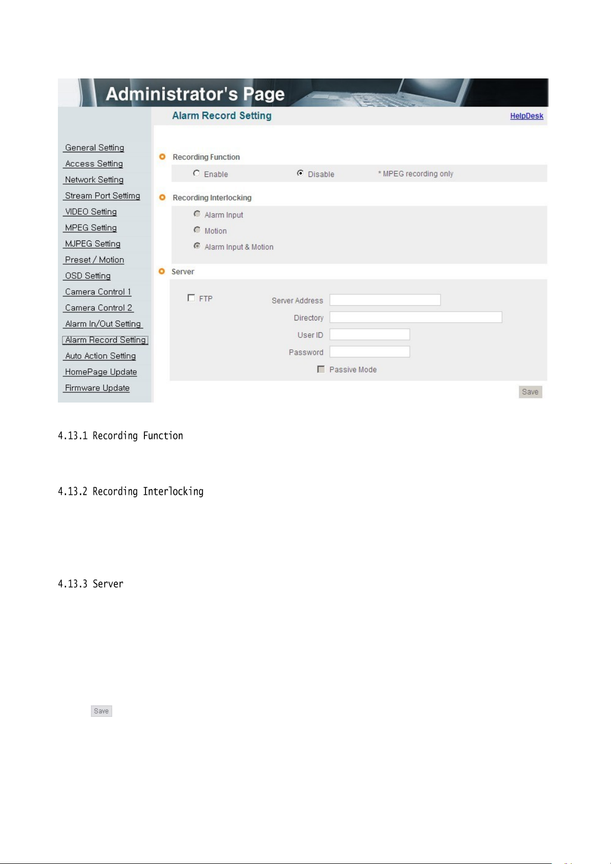
4.13 Recording Functio
n
Select recording 'Enable'
or 'Disable'
[
Pic. 4-22] Alarm Record Setting
upon alarm events.
1)Alarm Input : Record by events only upon alarm
2) Motion : Record by events only upon motion det
3) Alarm Input & Motion : Record by events upon alarm input and motion det
input.
ection.
ection.
1) FTP Server : To send the recorded video to FTP server upon alarm ev
Input FTP server address, folder name, user IP and
FTP folder
name(mandatory).
passw
ent,
ord,
[Ref
erence ] Video files recorded in FTP server can be played by supplied player, with the CMS.
Click
' '
button to save

56
4.14 Auto Action
Setting
Set the program to operate such as last action, Preset, Sequence, Auto Pan
when the camera turns on.
If there is no action,
the camera will be specific action such as "Preset", "Sequence" or "Auto pan".

57
4.15 Homepage Update
[
Pic. 4-23] Homepage Update
Homepage update function is for user to upload the main page of the unit onto user's homepage
User's
homepage is composed of 3 files as like index.html, top.htm, main.htm. The file for user to use
.
is main.htm. After making web
function of 'Home
file is not uploaded). User homepage cannot exceed 300Kbyte and 800x600(Image siz
If user wants to re-make user's
page
Update', then main.htm page is to be the 1st main page of the camera(Image
page(main.htm)
homepage into default, click 'Default
and save it as file name of main.htm, upload by the
Home Page Upl
e).
oad

58
4.16 Firmware Upgrad
e
In case firmware is upgraded in the near future, our upgrade server(h
ttp://ipcctvlink.com)
wi
ll
automatically upgrade firmware of the unit. Upgrade is only supported via
[
Pic. 4-24] Firmware Up
date
internet.
Display current software and hardware version.
Upgrade server address is "http://ipcctvlink.com"
as default addr
ess.
If there is the wrong address, re-check and input the address and click
C
lick 'Update'
on 'Remote
Update' and the massage is displayed as follow.
[
Pic. 4-25] Firmware Remote Up
date
'
' button.

59
This will be automatically upgraded upon clicking 'Downl
server and checking version
.
oad'
button after
connecting
to upgrad
e
[
Pic. 4-26] Firmware
Download
'
Downl
oading' message will be shown until completion of update(it may take time according to
network situation). Upon completion of upgrade, there appears message showing upgrade result.
Message as follow is showing that upgrade has been correctly done. Click 'R
to restart sy
stem
.
[
Pic. 4-27] Upgrade completion
estart'
in 'System R
estart'
If picture is displayed as follow, it means that this unit has been upgraded to the latest version, there
is no need to update any m
ore.
[
Pic. 4-28] Check of upgrade version
If user found message as follow, there is an error in
connection
to upgrade again. If user keep finding message as follow or cannot upgrade, contact an au
technician.
or DNS server address in '3. Network Setting' and try
connection
to upgrade server, re-check
internet
thorized

60
[
Pic. 4-29] Upgrade server
This way is to use software file on user's
connection error
PC to upgrade(Regarding procedure, refer to rem
ote
firmware upgrade.).
In case of upgrade sequence, choose new software file with "Search" button and press
"Upgrade"
button. Restart the camera after upgrade completion message. In case of local upgrade, it does not
care firmware version.
This is the function to restart the camera sy
stem.

61
Chapter 5.
IP Finde
Use of IP finder
r
··············································································

62
Chapter 5. IP Finde
NO
Descr
iptio
n
NO
Descr
iptio
n
1
Find IP
12
List of the unit
2
Delete the
lis
t
13
Input IP address
3
IP address of the u
nit
14
Input Gateway
4
MAC information of the u
nit
15
Input Subnet Mask
5 Gateway
16
MAC address
inf
ormati
on
6
Subnet Mask
17
Administrator ID
7
Static IP/Dynamic IP
18
Administrator pa
ssw
ord
8
Administrator ID
19
Change the information to setting
values on 13,14,15
9
Port number to connect to
web
20
Test of co
mmu
nication
(Ping)
10
Set dynamic IP
21
Exit the
pro
gra
m
11
Set static IP
22
Status of the
pro
gra
m
r
5.1 Use of IP finder
This program is the utility to find out the unit connected to local network. It is useful for the
application of the unit connected by DHCP function.
It can provide you the information such as IP address, MAC, web port for easy installation and use.
5.1.1 Run IP finder program
Double click "IP Finder" file to open the program, [Pic. 5-1] will be shown.
Description of IP finder function
[
Pic. 5-1] IP Find
er

63
5.1.2 Find IP addr
Click button to find IP address of the unit on local
ess
network
.
[
Pic. 5-2] IP Finding
Below picture will be shown, after IP Finding comp
lete
.
[
Pic. 5-3] IP Finding comp
leted
You can connect easily by inputting the information of IP address and web port. In addition, you ca
get the information of MAC address required on registration of server.
n

64
5.1.3 Change IP addr
After finding IP address, if you want to change IP address, Gateway or Subnet Mask, double click IP
address you want to change and [Pic. 5-4] will be shown.
ess
<Procedure>
①Double click IP address you want to cha
②Input the information you want to cha
[
Pic. 5-4] Change of IP addr
nge.
nge.
ess
③Input Password( ).
④Click button to change the informa
⑤Click button one more time to check the changed
tion.
inf
ormat
ion.
⑥Double click the changed IP address and click button to check.
⑦Click button to exit the
program.

65
[Pic. 5-5] Ping

66
Chapter 6.
Basic Network
6.1 Public IP
6.2 Private
6.3 Ping test
······································································································
IP
········································································································
········································································································
68
69
70

67
Chapter 6. Basic Network
This chapter is the basic explanation for
6.1 Public IP
installation.
[
Pic. 6-1]I
nternet
environ
ment
All hosts connected to internet have the exclusive number called IP addr
Communication among hosts is available by using it.
There are two ways to allocate IP address. One is fixed by the way of static IP address
whenever
Configuration
connected
to internet. And the other is assigned by a server using Dynamic
Protocol (DHCP). It is Dynamic IP.
ess
.
Hos
In case of Dynamic IP, when turn off the computer, automatically return the IP to DHCP due
to using that IP in circu
lation.
Determined way of assigned IP by network policy so please ask to network administrator or
ISP(Internet Service Provider)
In case of using Firewall, the camera might be out of working. Please ask network administrator then
t
open the service port

68
6.2 Private IP
[
Pic. 6-2]I
nternet connection
by IP sharing
device.
The most common use of these addresses is in home networks, since most Internet Service Providers
(ISPs) only allocate a single IP address to each customer, but many homes have more than
one
networking device (for example, several computers, or a printer). That’ s why we recommended use
IP sharing device. IP sharing device uses only one public IP. Private IP is allocated such as
192.168.xxx.xxx, and can not be used as public IP.
When using the router, connect the router and input IP address of the unit(IP address of the unit is
as 192.168.1.8 on ex-fac
tory) in DMZ menu.
If the user cannot use the DMZ function because there is no DMZ menu in the router or some other
reasons, go into Port Forwarding or NAT menu on the router and map the port of the unit one by
one.
[Ref
erence]
*
For more detailed information, please refer to manual of IP sharing device.
Private IP range to use private address is hereby.
CLASS A : 10.0.0.0
~ 10.
255.255.255
CLASS B : 172.16.0.0 ~ 172.31.255.255
CLASS C : 192.168.0.0 ~ 192.168.255.255
set

69
6.3 Ping test
Ping is the test to check response among the devices connected with
Input "Ping IP address" to command window of PC and check response.
network.
In case of Ping failure, there is some
By firewall, this test can not be ava
communication
ilable.
problem between the devices
.

70
[
Ping Failure]
[
Ping Success]

71
Chapter 7.
A
ppendix
Basic setting table
Troubleshooting of cable
Troubleshooting of network
·····························································································
connection
connection
·······································································
····································································

72
Chapter 7. Appendix
I
tem
Default(Basic se
tting)
Remarks
Netw
ork
Static IP / Dynamic IP
Static IP
IP Server
Enable
IP addr
ess
192.168.1
.8
Ga
teway
192.168.1
.1
Subnet Mask
255.255.25
5.0
Web Connection Por
t
80
ㆍDo not duplicate the same Por
t.
ㆍUse the number under 9999 of por
t.
Authentication
Control Port
Video Streaming Port
9000
(n)
Remote Control Port
9001(n+1
)
Available with CMS only
ID and Passw
ord
A
dministrator
ID/Pa
ssw
ord
admin/a
dmin
User ID/Passw
ord
root/root, guest/guest
Domain of Related Server
DDNS Server
ipcctvlink.com
Domain of server to connect to register IP.
Alarm Server
ipcctvlink.com
Domain of server to connect to send event
upon detection of sensor or motion
.
Upgrade Server
ipcctv
link.com
Domain of server to connect to download
upgraded program
.
Plug-in
Download
Server
ipcctvlink.com
Active-
x
Video setting
C
ompressed
Resoluti
on
MPEG:VGA JPEG:QVGA
Frame Rate
NTS
C:CIF/VGA
30fps,QVGA 1
5fps
PAL:CIF/VGA25fps,QVGA 12
.5fps
Bit Rate
512kbp
s
Other setting
Time
Zon
e
Asia/Seoul(K
orea
)
7.1 Basic setting table
[Ref
erence]
Administrator will be automatically returned to the above default value.
In case to reset hardware and network setting, ID and password of user and
73
Troubleshooting of cable connection
7.2.1 Power cable connection check
Check if the power cable is connected to the camera
※ Check
whether
the output of the adaptor is regu
or 500mA(for No IR LED model)
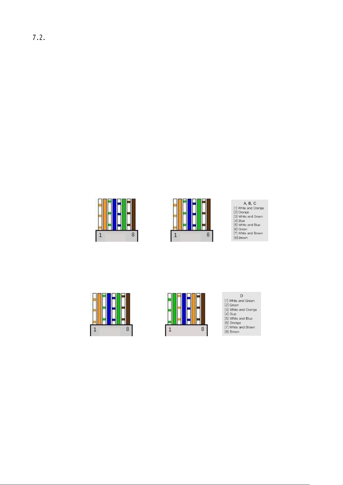
7.2.2 Network cable(LAN Cable)
Check whether the network cable is connected correctly.
[Cau
tion] Use direct LAN Cable or cross cable according to network
2 Video check)
① Cable check
[Direct Cable]
Hold each end of both side and check if same color's cable is connected to same location in
RJ45 jack or
not.(Connection
prop
erly.
lated
12V
connection check
with IP sharing device or cable modem)
DC
1A(for built-in IR LED model)
condition.
(Refer to chapter
[Cross Cable]
Hold each end of both side and check whether 1, 2(Tx+, Tx-)
not.(Connection
A. B.
and 3, 6(Rx+, Rx-)
with PC)
C. D.
are cross or

74
Troubleshooting of network connection
7.3.1 Cannot connect with
network
Check with "7.2.2 Network cable(LAN cable) and cable
① In case camera uses Sta
tic/Pub
lic
IP : input "Ping IP address" to command window of PC a
check response.
connection
check". [PING Test]
nd
② In case camera uses dynamic/public
and connect PC with the camera through cross cable and ping test by entering
IP : If user cannot find camera's
IP address, reset hardwar
"192.
168.1.8".
③ In case camera uses private IP through IP sharing device : Do ping test of private IP address
for camera in PC that is connected in the local network through IP sharing device.
[Ref
erence]
Please refer to "PING Test of Basic Network".
If "ping test"get response, network setting for camera is done correctly.
Ping test is okay but there is no
connection,
check with "7.3.2 check port
set
ting".
7.3.2 Check port setting
If user can't connect with camera even though "Ping test" is okay, please check port setting by the
following
The unit uses 3 ports as follow.
Web Connection Port : Port 80 TCP
Authentication,
ste
ps.
Control and video streaming port : Port 9000 TCP
① Not available to connect to
If it is not available even to connect to web, check web
web
connection
port because web connection por
e
set
t
may be set with other number is not
Use IP Finder
[Ref
erence]
program.(Default
Web port "80" can not be available in some internet service.
In this case, go to the a
"80".
value of web port is
dministrator's
"80
".)
page and change the web port.
② Problem in video m
onitor
ing
In case there is problem in video monitoring even though there is no problem in web connec
check if "Authentication and Control Port" and "Video Str
eaming.
Port" of the unit is set on IP sharing device(Refer to the manual of IP sharing device regarding Por
f
orwar
ding).
[Ref
erence]
It is strongly recommended to register the number under 9999 of port.
Port Number more than "10,000" can not be available in some
network.
tion,
t

75
Chapter 8. Troubleshootin
g
 Loading...