


XL-ICA-13x, 20x
User
Manual

User Manual of Network Camera
Table of Contents
Chapter 1 Network Camera Connection................................................................................................
1
1.1 Cable Network...........................................................................................................................1
1.2 Wireless Network......................................................................................................................1
1.3 Network Connection.................................................................................................................2
Chapter 2 Network
Access ..................................................... ............................................................... .3
2.1 Access over IE Browser..............................................................................................................3
2.1.1 Live View.........................................................................................................................3
2.1.2 Parameters Configuration ...............................................................................................5
2.1.3 Wireless Parameter Configuration................................................................................16
2.2 Access over Client So
ftware
....................................................................................................18
2.2.1 Live View.......................................................................................................................18
2.2.2 Camera Parameters Configuration................................................................................19
2.2.3 Wireless Parameter Configuration................................................................................21
Chapter 3 Access over In
ternet
............................................................................................................
23
3.1 Access network camera with staticIP.....................................................................................23
3.2 Access network camera with dynamicIP................................................................................24
Appendix 1 SADP Introduction.............................................................................................................
28
Appendix 2 Port Map ...........................................................................................................................
30
Appendix 3 Pin Definition ....................................................................................................................
32
1
User Manual of Network Camera
Chapter 1 Network Camera
Connection
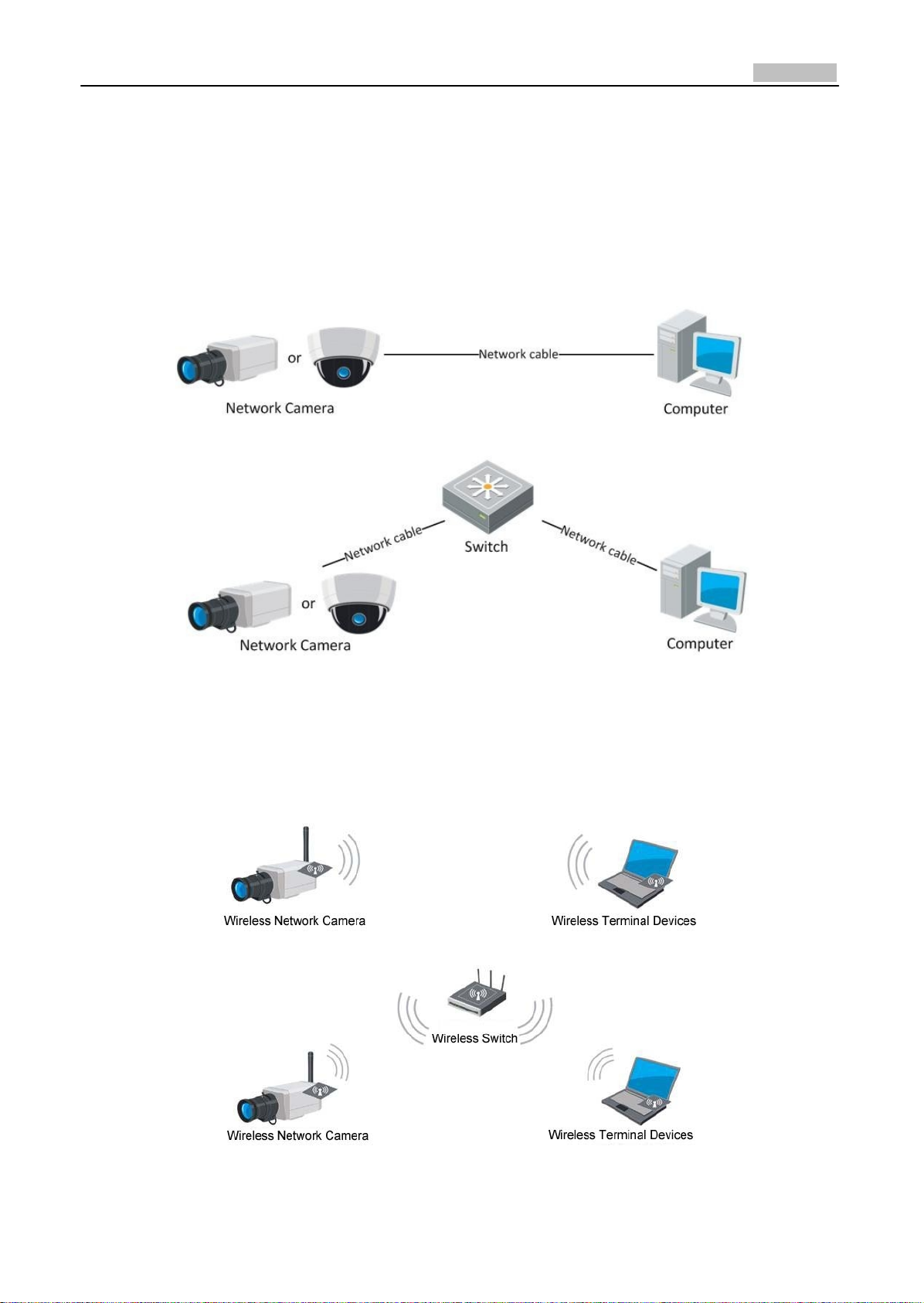
1.1 Cable Network
Two methods can be used to connect between network camera and PC, shown as below:
Fig. 1.1.1 Cross Line Connection
Fig. 1.1.2 Direct Line Connection
1.2 Wireless Network
Note: This section is only for wireless network camera with mark '‐W' in the model number.
Fig. 1.2.1 Peer‐to‐peer Communication Through Wireless
Network
Fig. 1.2.2 Communication Via Wireless Switching Equipmen
t
2
User Manual of Network Camera
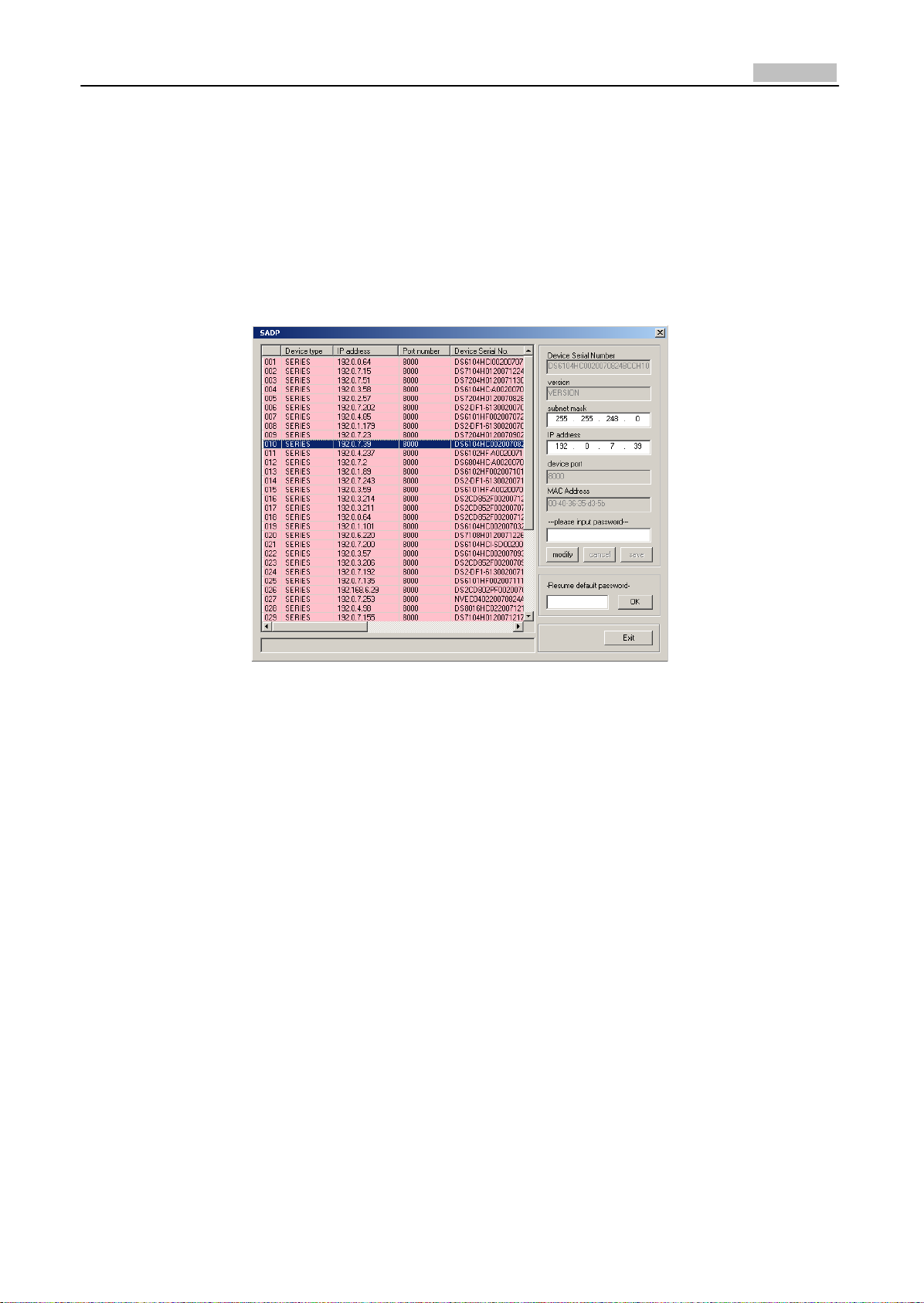
1.3 Network Connection
Before visiting network camera over network, user should acquire its IP address first. SADP is a
software tool which can automatically detect network device in the LAN and give the device’s
information like IP address, mask, port number, device serial number, software version, etc., as
shown in Fig. 1.3.1.
Fig. 1.3.1
Select the device, and set its IP address and mask at the same network segment with the PC.
For the detailed introduction of SADP, please refer to Appendix 1.
Note: The network camera is set with the factory default IP address of “192.0.0.64”, the port of
“8000”, the super user name of “admin” and the password of “12345”.
3
User Manual of Network Camera
Chapter 2 Network Access
After hardware installation, user can view live video and configure parameters for the network
camera, including IP address, subnet mask and port number, etc. The following two methods can be
used to access the camera:
1. View live video and configure parameters over IE browser.
2. View live video and configure parameters over client software.
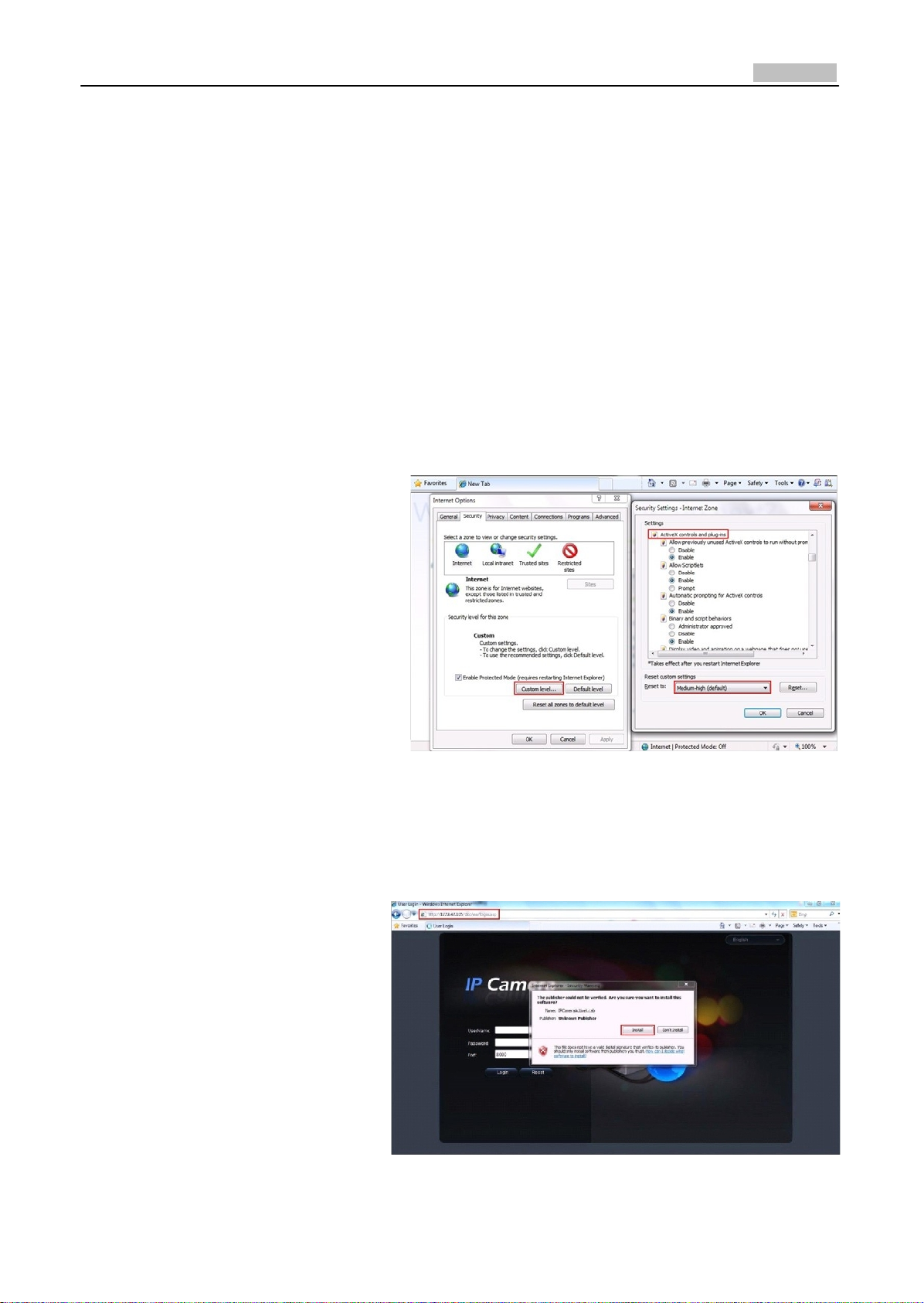
2.1 Access over IE Browser
Before access to the camera over IE
browser, user should adjust the security
level.
Open the IE browser, and set the
security level to Medium in Tools/
InternetOptions/Security/Custom
Level..., and enable or prompt Activex
Control and Plug‐in directly as well.
Fig. 2.1.1 Adjust the Security Level
2.1.1 Live View
Step 1: Install Active‐X Control
Type the IP address of the network
camera and press Enter, then the
ActiveX mention dialog will pop
up.
Click Install to install the ActiveX
control.
Fig. 2.1.2 Install the ActiveX Control
4
User Manual of Network Camera
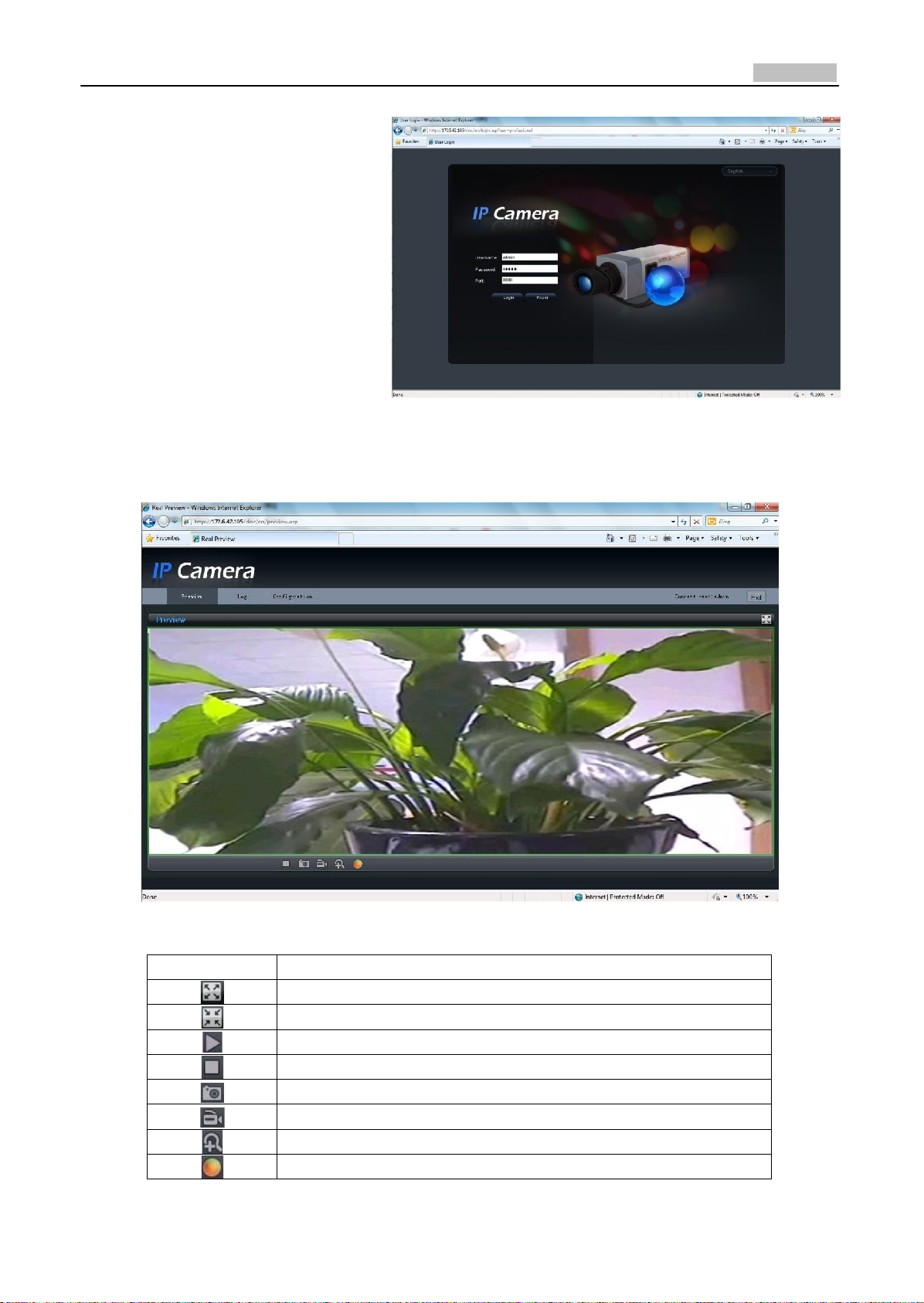
Step 2:
Input the Username (default:
admin), Password (default: 12345)
and Port (default: 8000) of the
camera, and then click [Login].
Fig. 2.1.3 Login Interface
Step 3: After successful login, user is allowed to view the live video. Refer to Figure 2.1.4.
Icons on Live View Page:
Fig. 2.1.4 Live View Page
Ic
on
De
scription
Full‐screen display mode
Exit full‐screen display mode
Start
Preview
Stop
Preview
Capture
Picture
Start/Stop
Recor
d
Digital Zoom
Video
Parameter
s
5
User Manual of Network Camera
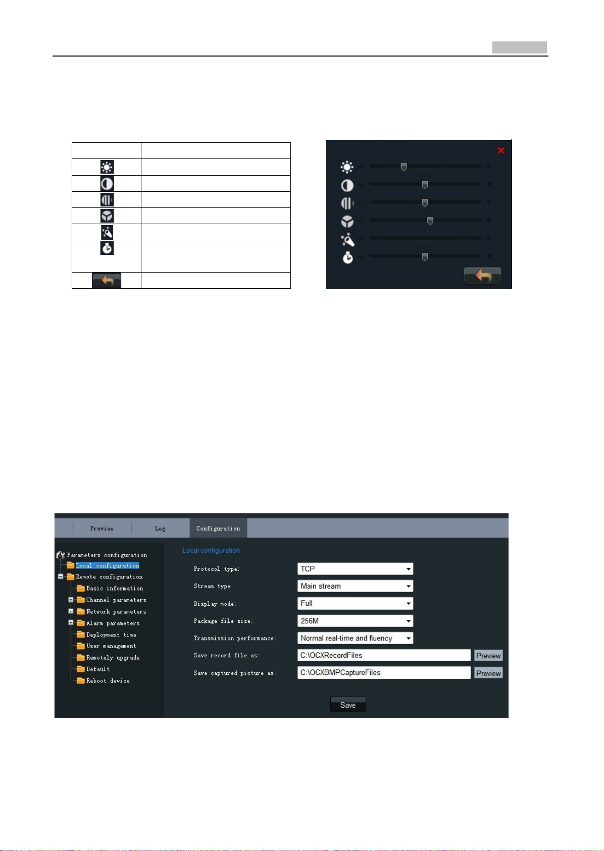
Digital Zoom:
Click mouse in the desired position of live video image and scroll the mouse to realize zoom in and
zoom out function.
Video Parameters:
IconDescription
Brightness: 0~100 configurable
Contrast: 0~100 configurable
Saturation: 0~100 configurable
Hue: 0~100 configurable
Gain: 0~100 configurable
Exposure time: 0~40000
configurable
Restore default
Fig. 2.1.5 Video Parameters
Note: Gain value is not configurable when the Day/Night mode is ‘Auto’.
2.1.2 Parameters Configuration
Click Configuration to enter the Parameters Configuration in
terface.
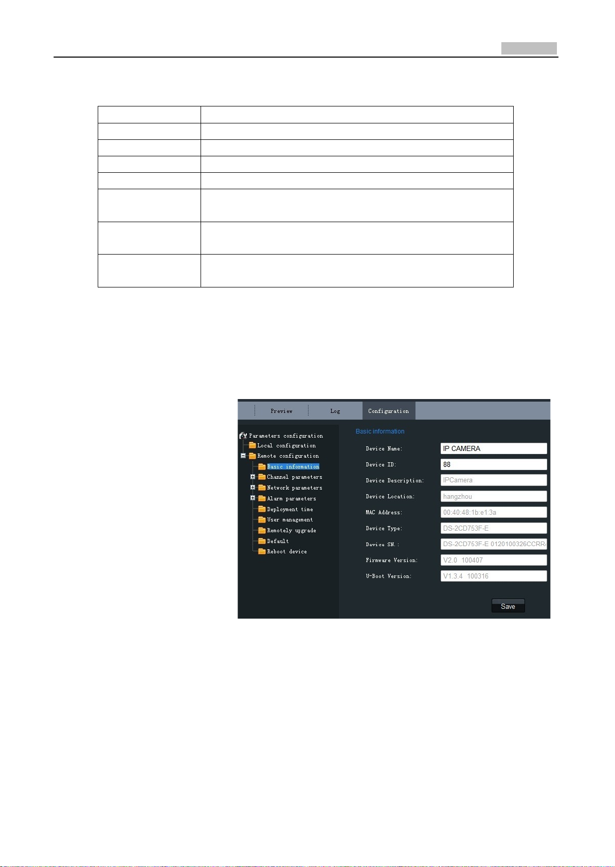
2.1.2.1 Local Configuration
Fig. 2.1.6 Local Configuration
6
User Manual of Network Camera
Local Configuration:
Parameters
De
scription
Protocol type
TCP and UTP
select
able
Stream type
Main stream and Sub stream selectable
Display mode
Full‐screen, 4:3 mode, 16:9 mode or adjustable to resolution
Package file size
128M, 256M, 512M selectable
Transmission
performance
Shortest delay mode, good real‐time, normal real‐time and fluency
and good fluency options selectable
Save record file as
The default directory for saving record files is C: \OCXRecordFiles,
which can be modified by user
Save captured
picture as
The default directory for saving captured files is
C:\OCXBMPCaptureFiles, which can be modified by
user
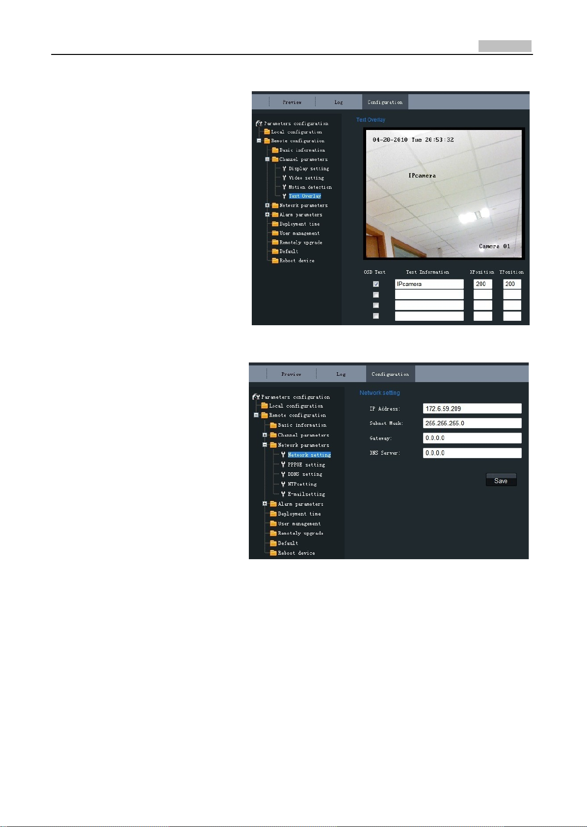
2.1.2.2 Remote Configuration
Basic Information:
In the Basic Information
settings interface, user is
allowed to set the Device
Name and Device ID, as well as
view the information of IP
camera, including Device
Description, Device Location,
MAC address, Device Type,
Device SN, Firmware Version,
and U‐boot Version.
Fig. 2.1.7 Basic Information

7
User Manual of Network Camera
Channel ParametersDisplay
Setting:
According to different
requirements, enable the
display of Date&Time and
Week by clicking the checkbox.
Different date formats can be
selected.
The OSD Status can be set to
transparent & flickering,
transparent & unflickering,
nontransparent & flickering, or
nontransparent & unflickering.
Fig. 2.1.8 Display Settings
Channel ParametersVideo Settings:
Fig. 2.1.9 Video
Sett
ings
Parameter
De
scription
Stream Type
Select stream type to Main stream or Sub stream
Resolution
Select the resolution for your need,
Image Quality
Select image quality to Highest, High, Medium, Low, Lower or Lowest
Stream Type
Select the bitrate type to Constant bitrate or Variable bitrate
Max. Bitrate
Select or custom bitrate according to the resolution
Multicast
Set the multicast address, with the default multicast of 0.0.0.0
RTSP Port
Set the RTSP port, with the default RTSP port of 554

8
User Manual of Network Camera
Channel ParametersMotion
Detection Setting:
Select the checkbox of Enable
motion detection to enable this
function.
Zone Settings:
Click Start draw button to draw
motion detection zone by
clicking and dragging the
mouse in the live video image.
User is allowed to draw
multiple motion detection
zones in the same picture.
When all zones have been set,
click Stopdraw to finish
drawing.
Sensitivity:
The sensitivity level can be set
to 0, 1, 2, 3, 4 and 5. When it is
set to 0, the sensitivity is
disabled.
Linkage:
The Linkage method can be
selected to either Email link or
Trigger alarm output.
Click "Save" button to save the
modified parameters.
Fig. 2.1.10 Motion Detection Zone Settings
Fig. 2.1.11 Motion Detection Linkage Settings
9
User Manual of Network Camera
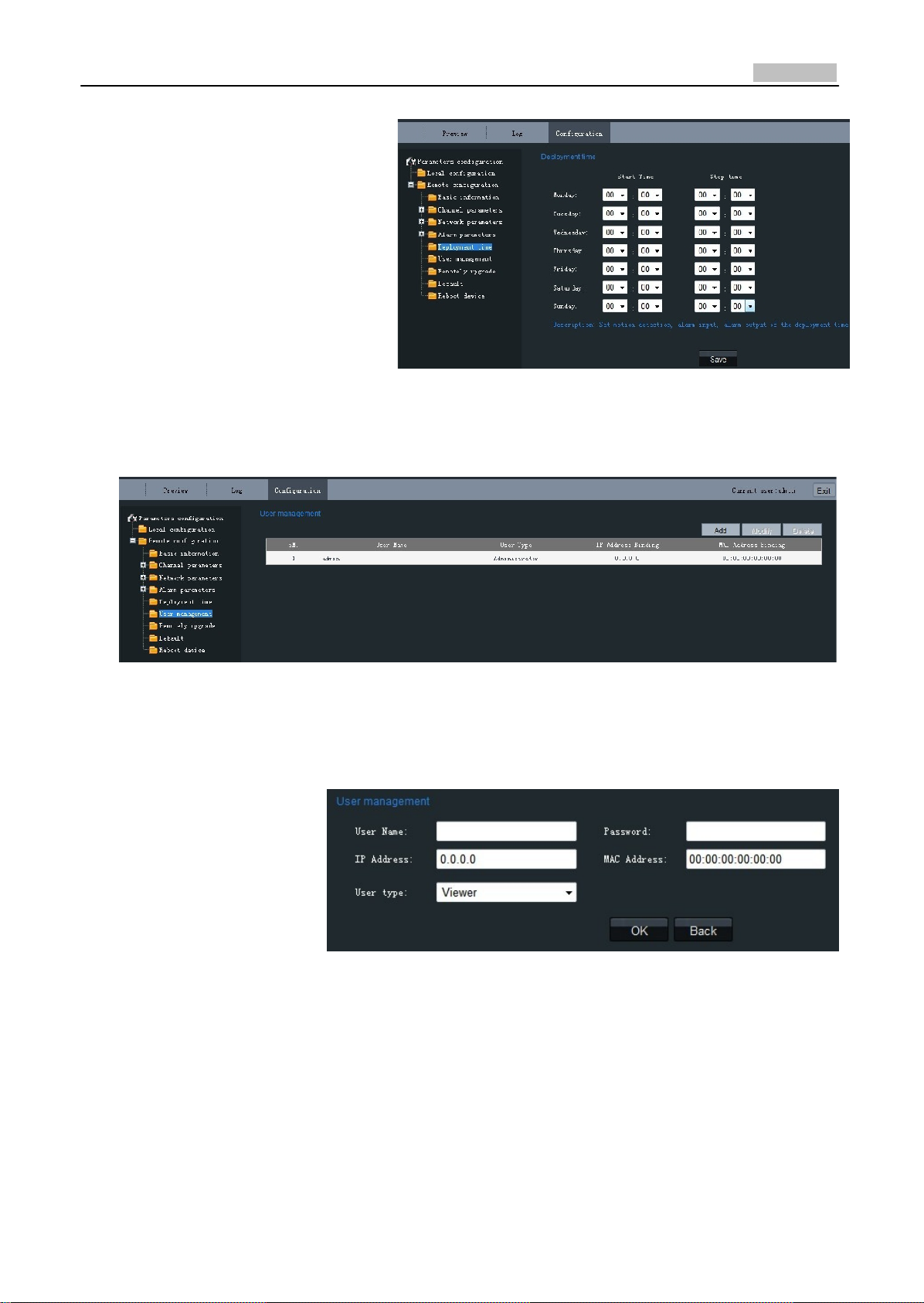
Channel ParametersText
Overlay Setting:
Input the characters in the Text
Information box and define the
OSD location in the image by
setting the XPosition and
YPosition, and then select the
checkbox of OSD Text. After
clicking Save to finish the
settings, the defined title will
be displayed on the image.
Note: The values of XPosition
and YPositon are relative to the
upper left corner origin of the
image.
Network ParametersNetwork
Setting: Set the
IP
A
ddr
ess,
Subnet
Mask, Gateway and DNS Server
of the network camera.
Click "Save" button to save the
modified parameters.
Note: Please reboot the
network camera to validate the
modified parameters.
Fig. 2.1.12Text Overlay Settings
Fig. 2.1.13 Network Settings

10
User Manual of Network Camera
Network ParametersPPPOE
Setting:
Click the checkbox of Enable
PPPOE to enable this
function.
Input the PPPOE user name
and password in the text box
and then click Save to finish
settings. After reboot, the
camera will obtain a public IP
address.
Click "Save" button to save
the modified parameters.
Note: Please reboot the
network camera to validate
the modified parameters.
Network ParametersDDNS
Setting:
Click the checkbox of Enable
DDNS to enable this function.
The protocol type can be set to
DynDNS or IPServer.
Click "Save" button to save the
modified parameters.
Note: Please reboot the
network camera to validate the
modified parameters.
If the protocol type is selected
to DynDNS, please input the
Server Address, e.g.,
members.dyn dns. org.
The User Name and Password
refer to the user name and
password registered in the
DynDNS website.
The Device Name refers to the
domain name applied in the
DynDNS website.
Click "Save" button to save the
modified parameters.
Note: Please reboot the
network camera to validate the
modified parameters.
Fig. 2.1.14 PPPOE Settings
Fig. 2.1.15 DDNS
Sett
ings
Fig. 2.1.16 DynDNS
Sett
ings

11
User Manual of Network Camera
If the protocol type is selected
to IPServer, please input the
Server Address of the IPServer.
Click "Save" button to save the
modified parameters.
Note: Please reboot the
network camera to validate the
modified parameters.
Network ParametersNTP
Setting:
Click the checkbox of Enable
NTP to enable this function.
Input the Server Address and
Port of NTP.
If the public network is
applied, please input the NTP
Server Address with provision
of time sync service, e.g.,
210.72.145.44.
In the private network is
applied, the NTP software can
be used to establish NTP server
to achieve time
synchronization.
Click "Save" button to save the
modified parameters.
Note: Please reboot the
network camera to validate the
modified parameters.
Fig. 2.1.17 IPServer
Sett
ings
Fig.2.1.18 NTP
Sett
ings

12
User Manual of Network Camera
Network ParametersE‐mail
Setting:
Through E‐mail settings, the
alarm message can be sent to
the designated E‐mail address
when alarm event occurs.
Input the SMTP server, SMTP
port, user name, password,
E‐mail sender and receiver, and
finally click Save to finish E‐mail
settings.
Click "Save" button to save the
modified parameters.
Note: Please reboot the
network camera to validate the
modified parameters.
Alarm ParametersAlarm
Input Setting:
Set the type of Relay Status
to NC or NO.
The Linkage method can be
selected to E‐mail link or
Trigger alarm output.
Click "Save" button to save
the modified parameters.
Alarm ParametersAlarm
Output Setting:
The Output Delay refers to the
length of time that the relay
remains in effect after alarm
occurs. The output delay time
can be set to 5sec, 10sec,
30sec, 1min, 2min, 5min, 10min
or Manual (manually disable).
Click "Save" button to save the
modified parameters.
Fig. 2.1.19 E‐mail
Sett
ings
Fig. 2.1.20 Alarm Input
Sett
ings
Fig. 2.1.21 Alarm Output Delay
Sett
ings
13
User Manual of Network Camera
Alarm Deployment Time:
The Deployment time can be set
to several days a week or to all
week, with only one period
configurable for each day.
Note: The alarm deployment
time setting is valid only when
the camera has already been
configured with the motion
detection, alarm input and alarm
output functions.
Fig. 2.1.22 Alarm Deployment Time Settings
Click "Save" button to save the modified parameters.
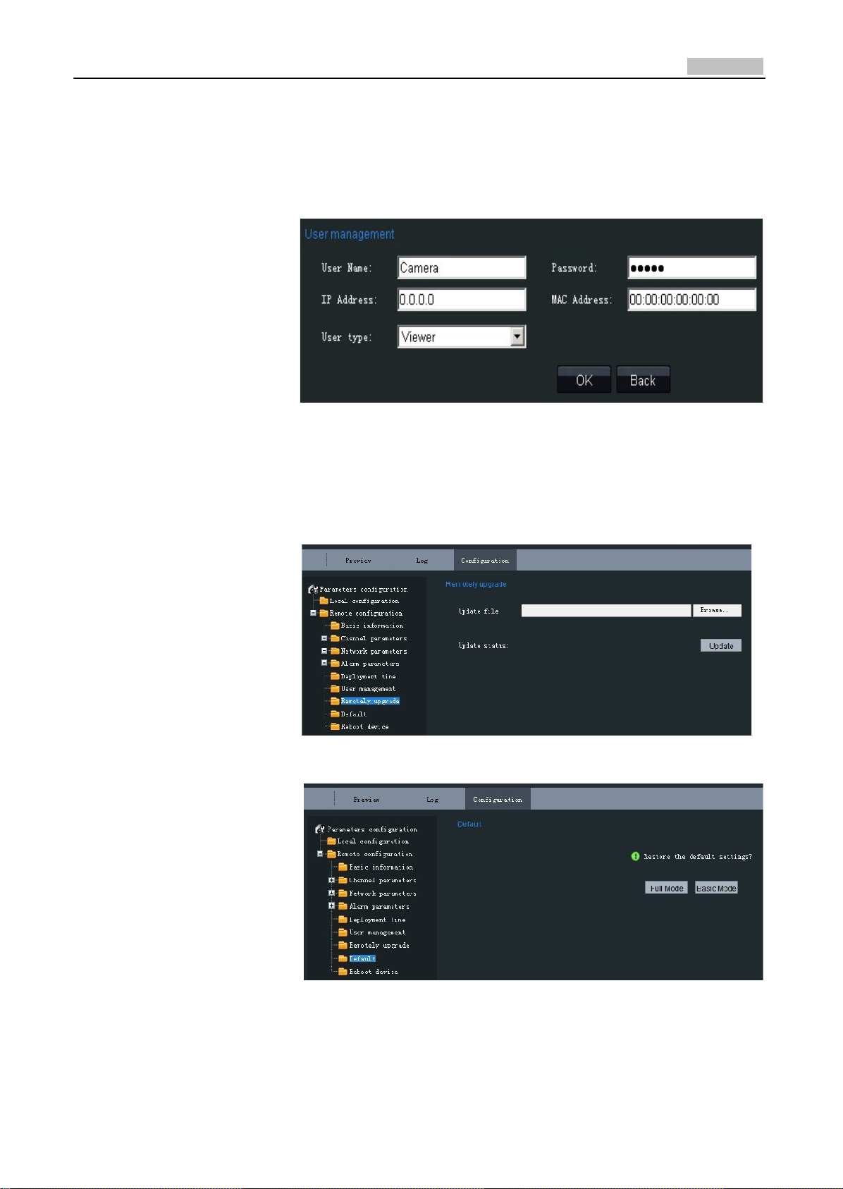
User Management:
Fig. 2.1.23 User Manag
ement
When the current login user is admin, it is allowed to create other users. Up to 15 users can be
created. Refer to Fig. 2.1.23.
Add User:
Click Add to enter the
settings interface as
shown in Fig. 2.1.24.
Input the user name,
password, IP address,
MAC address, and then
select user type. Finally,
click OK to finish the user
addition.
Fig. 2.1.24 Add
User
14
User Manual of Network Camera
Modify User:
Click Modify to enter the
settings interface as shown
in Fig. 2.1.25.
It is allowed to modify the
user name, password, IP
address, MAC address, and
then select user type.
Finally, click OK to finish the
user modification.
Note: Only the password of
the user admin can be
modified.
Fig. 2.1.25 Modify
User
Remote Upgrade:
Click Browse to select the
local update file and then
click Upgrade to finish
remote upgrade.
Restore Default:
Select Full Mode or Basic
Mode to restore the default
settings.
Note:
The Full Mode refers to
restore all parameters to the
factory default settings.
The Basic Mode refers to
restore the parameters to
factory default settings
except IP address, subnet
mask, gateway and port.
Fig. 2.1.26 Remote Upgrade
Fig. 2.1.27 Restore Default
15
User Manual of Network Camera
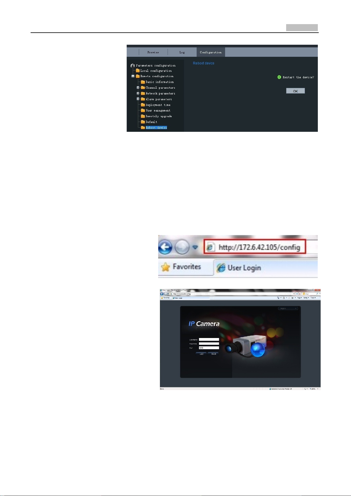
Reboot Device:
Click OK to reboot the
network camera.
Fig. 2.1.28 Reboot Device
2.1.2.3 Advanced Configuration
Note: This chapter is applicable to professional configuration.
1: Input the IP address of the
network camera and “config”
(Such as http://172.6.42.105/config),
and then click [Enter].
2: Type the Username (default:
admin), Password (default: 12345)
and Port (default: 8000) of the
camera, and then click [Login].
Fig. 2.1.29
Fig. 2.1.30
16
User Manual of Network Camera
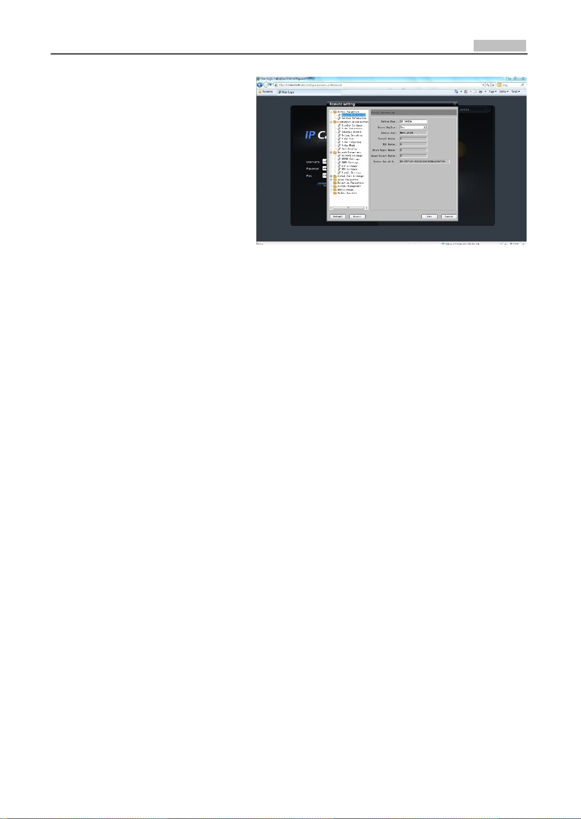
3: The “Remote config” dialog will
pop up, which has more advanced
settings including schedule record
and HDD settings and so on.
Fig. 2.1.31
Please refer to “Client Software‐4000(v2.0)_ENG.pdf” for a more detailed parameters configuration.
You can find the document in the PC Operating System after the installation of client software 4000
v. 2.0 by selecting “Start”‐> “All Programs”‐> “client software 4000 v. 2.0”.
2.1.3 Wireless Parameters Configuration
Note: This section is only for wireless network camera with mark '‐W' in the model number.
Before configuring the wireless network camera, please set the wireless router first. For more
details about wireless router configuration, please refer to the wireless router configuration
instructions.
There are two network interface cards in the camera: wired network interface card and wireless
network interface card. The factory default settings of wired network interface card are IP address:
192.0.0.64, port number: 8000, superuser: admin, superuser password: 12345, while the default IP
address of wireless network interface card is 192.168.1.64. Before accessing to the wireless network
camera through wireless network, use the wired Ethernet port of the wireless network camera to
configure parameters of wireless network interface card. The configuration steps are the same way
as section 1.3.
If users want to configure the wireless parameters through IE browser, enter the remote parameter
settings interface first. Refer to section '2.1.2.3 Advanced Configuration' for more detailed settings.
After entering the remote parameter settings interface, select "W iFi parameters"‐> "W iFi Settings"
to enter the WiFi settings interface, as shown in figure 2.1.32.

17
User Manual of Network Camera
Fig. 2.1.32 WiFi Settings In
terface
In the WiFi settings interface, if user select Ad‐Hoc mode as the operating mode, please set the PC's
wireless IP address in the same network segment as the IP address of wireless network camera.
Select "V iew Wireless Networks" in the computer's "Wireless Network Connection". Find the device
which has the same name as the SSID number of the wireless camera. Then point‐to‐point
communication through wireless network is established successfully. So, there is no need to use an
Access Point (AP) between the PC and wireless network camera.
If users need to enable encryption, select the appropriate
corresponding encryption parameters.
encryption type and set the
In the remote parameter settings interface, select "WiFi parameters"‐> "Wlan Settings" to enter the
Wlan settings interface, as shown in Fig. 2.1.33.
Fig. 2.1.33 Wlan Settings In
terface
In the "Wlan settings" interface, user can set the wireless network camera's parameters like wireless
IP address, subnet mask, gateway and DNS server address, etc. Unplug the network cable from

18
User Manual of Network Camera
wireless network camera. The wireless network camera now can be accessed through wireless
network after the related network parameters have been set. The way that accesses to wireless
network camera through wireless network is similar to cable network. Refer to section 2.1.
2.2 Access over Client Software
Please refer to “iVMS‐4000(v2.0) introductor.pdf” for detailed client software installation. You can
find the document in the PC Operating System after the installation of client software 4000 v. 2.0 by
selecting “Start”‐> “All Programs”‐> “iVMS 4000( v. 2.0)” ‐> “ iVMS 4000( v. 2.0)”.
2.2.1 Live View
Right click to add devices in the setup interface of client software. Please refer to “iVMS‐4000(v2.0)
introductor.pdf” for more detailed device added process. You can find the document in the PC
Operating System after the installation of client software 4000 v. 2.0 by selecting “Start”‐> “All
Programs”‐> “iVMS 4000( v. 2.0)” ‐> “iVMS 4000( v. 2.0)”.
Click Preview, and then double click the device name in the left tree to view the live video. Refer to
Fig. 2.2.1.
Fig. 2.2.1
Preview
Please refer to “iVMS‐4000(v2.0) introductor.pdf” for more detailed parameters configuration. You
can find the document in the PC Operating System after the installation of client software 4000 v.
2.0 by selecting “Start”‐> “All Programs”‐> “iVMS 4000( v. 2.0)” ‐> “iVMS 4000( v. 2.0)”.
19
User Manual of Network Camera
2.2.2 Camera Parameters Configuration
Note:
Different types of network cameras maybe have different configuration parameters in the interface
of “Config Sensor Parameters”. This section takes a type of network camera for example to
introduce configuration parameters in the interface of “Config Sensor Parameters”. If the
information in the actual interface of “Config Sensor Parameters” is not different from the
information shown in this section, then subject to the actual interface information.
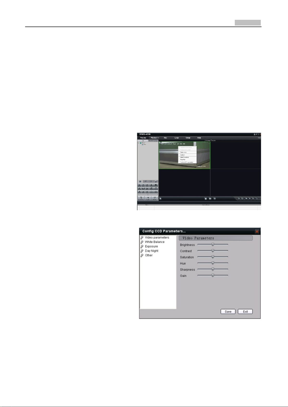
For viewing better image, you can set the parameters of the camera, and operate as following:
Step 1:
Right click in the preview window, and
click [Config Sensor Parameters…], then
the [Config Sensor Parameters…] box will
pop up.
Step 2: Video Parameters Configuration
Adjust the value of “Brightness”, “Contrast”,
“Saturation”, “Hue”, “Sharpness” and
“Gain” for your need, which can be set
from 1 to 100.
Fig. 2.2.2 Sensor Parameters
Fig. 2.2.3 Video Parameters

20
User Manual of Network Camera
Step 3: White Balance Configuration
Select the mode to Auto1 or Off for your
need.
Step 4: Exposure Configuration
Select “Exposure time” and “Iris mode” for
your need.
Step 5: Day/Night Mode Configuration
Select
“Day”, “Night” or “Auto” mode in
Mode and adjust the value of “Day‐>Night”,
“Night‐>Day”, and “Filter time” for your
need.
Fig. 2.2.4 White Balance
Fig. 2.2.5 Exposur
e
Fig. 2.2.6 Day/ Night Mode

21
User Manual of Network Camera
Step 6: Other Parameters Configuration
Select the value of “Power Line”, “Mirror”,
“E‐PTZ” and “Local Output”.
Fig. 2.2.7 Other Parameters
Please refer to “iVMS‐4000(v2.0) introductor.pdf” for more detailed parameters configuration. You
can find the document in the PC Operating System after the installation of client software 4000
v. 2.0 by selecting “Start”‐> “All Programs”‐> “iVMS 4000( v. 2.0)” ‐> “iVMS 4000( v. 2.0)”.
2.2.3 Wireless Parameter Configuration
Note: This section is only for wireless network camera with mark '‐W' in the model number.
Click “setup” in the client software to enter the devices management interface. Right click the
device that needs to be configured, select “Remote Configuration” to enter the remote
configuration interface.
The way to configure the parameters in the client software is the same as the way in IE browser.
Please refer to section 2.1.3 for more detailed parameters configuration.

22
User Manual of Network Camera
Fig. 2.2.8 Client Software Wireless Configuration Interface

23
User Manual of Network Camera
Chapter 3 Access over
Internet
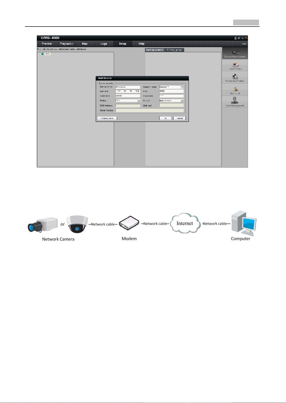
3.1 Access network camera with static IP
When there is a static IP from an ISP, open some ports (such as 80 and 8000 ports) in the router.
Then a user can visit it through a web browser or client software via the internet. The steps for port
forwarding are different for each model of router. Please call the router manufacturer for assistance
with port forwarding or visit www.portforward.com.
Note: Refer to Appendix 2 for a detailed explanation about Port Map.
Users can directly connect the network camera to the internet without using a router.
Fig. 3.1.1 Access IPC through Router with Static
IP
Fig.3.1.2 Access IPC with Static IP dir
ectly
For the client software to view the camera, in the adding equipment column, select the normal
model, and then fill in the IP info.
24
User Manual of Network Camera
Fig. 3.1.3 Selecting Normal
IP
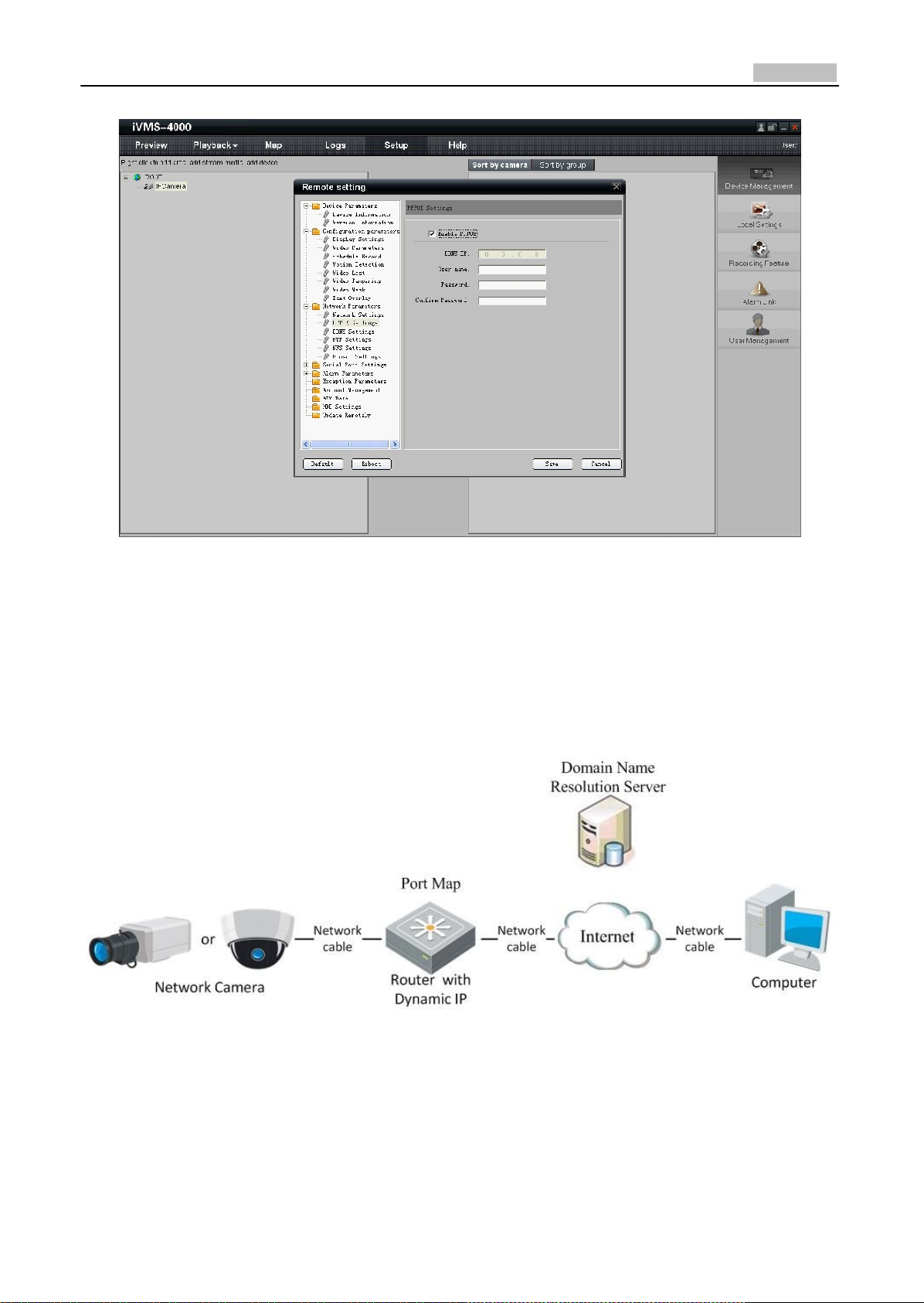
3.2 Access network camera with dynamic IP
Fig. 3.2.1 Access IPC through PPPoE Dial‐up
This camera supports the PPPoE auto dial‐up function. The camera will get a public IP address by
ADSL dial‐up after the camera is connected to a Modem; First, access to the network camera
through local network, select “Configure””Right Click the Device”, “Remote Configuration”, and
finally select “PPPoE Settings” under “Network Parameters” to fill in the PPPoE user name and
password and confirm the password. Please restart the network camera after completion of
configuration. Then the network camera can obtain a dynamic IP from an ISP operation business.
However, the obtained IP address is dynamically assigned via PPPoE, so the IP address always
changes accompanied with modem rebooting.
25
User Manual of Network Camera
Fig. 3.2.2 PPPoE configuration Dialog box
It is inconvenient to view a network camera with a dynamic IP, therefore, users should register with
a dynamic DNS provider. (Such as DynDns.com)
Domain name resolution contains normal domain name resolution and private domain name
resolution. First, we will introduce normal domain name resolution.
1. Normal Domain Name Resolution
Fig. 3.2.3 Normal Domain NameResolution
Apply a domain name from a domain name provider, then view the camera via the applied domain
name. If the camera connects to the internet via a router, users should port forward the router.
Please refer to Appendix 2.
Input domain names in the client software or IE to view the network cameras. Take the client

26
User Manual of Network Camera
software configuration as an example.
Fig. 3.2.4 Selecting Normal Domain Mode
27
User Manual of Network Camera
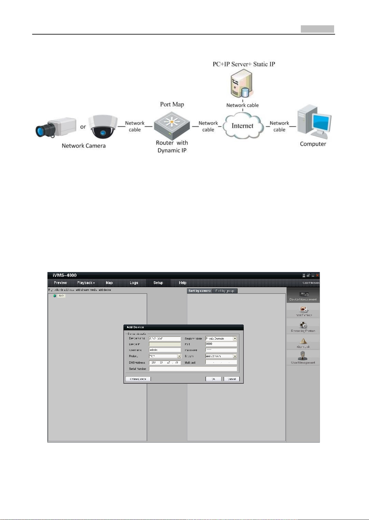
2. Private Domain Name Resolution
Fig. 3.2.5 Private Domain Name Resolution
A PC with a static IP which is running the domain name resolution service is necessary.
When the network camera connects to the internet through PPPoE and obtains an IP address, it will
send its name and IP address to the resolution server. When the client software connects to the
network camera, it will connect to the resolution server and tell the resolution server the expected
camera’s name. And the server will find the camera from all the registered cameras and send its IP
address to the client software. Once the client software gets the IP address, it can connect the
network camera.
Fig. 3.2.6 Selecting Private Domain Mode
28
User Manual of Network Camera
Appendix 1 SADP Introduction
1. Brief introduction
SADP (Search Active Devices Protocol) is a kind of software which can automatically search
network speed dome in LAN. User can modify the IP address, subnet mask and port of the
device without visiting IP address of the device. Additionally, password of the super user in this
device can be recovered as default.
SADP software needs to support SADP, so we should install WinPcap at first, which is placed at
the directory of SADP software.
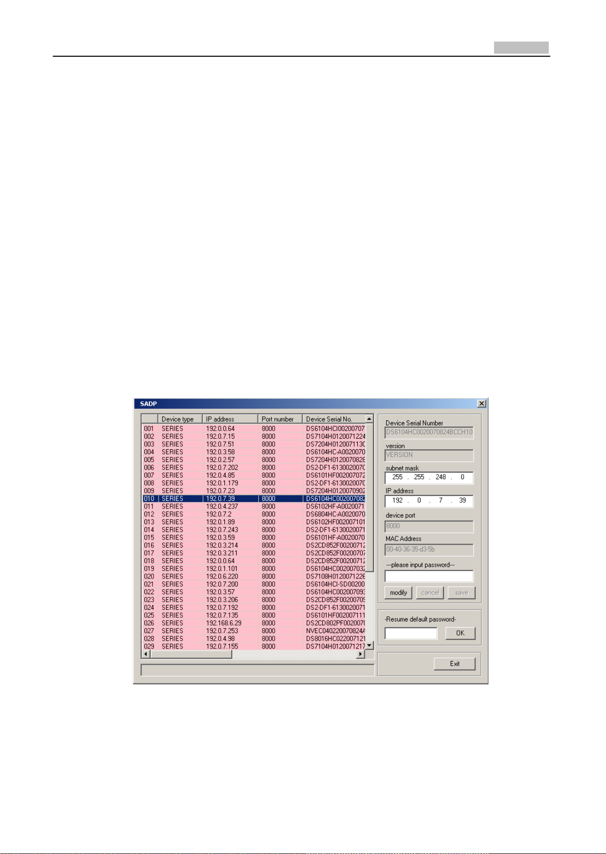
2. Search active devices online
After installing WinPcap, double click sadpdlg.exe. The software will start to search active
devices in LAN, and device type, IP address, Port number, Device Serial No., subnet mask, MAC
address, the number of channels, main control and encoding version and device initiating time
are showed in the list, as following:
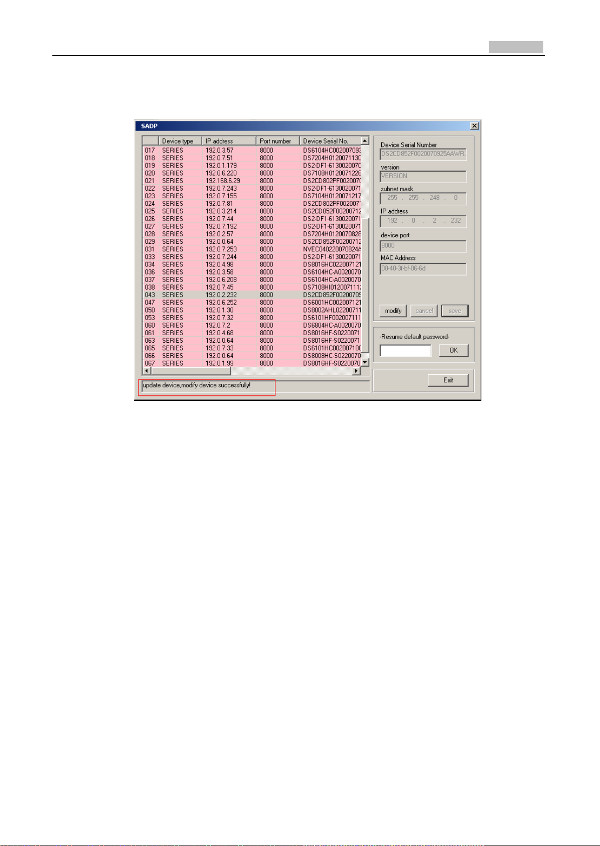
3. Modify device information
Select the device that needs modification in the device list, then basic information of the device
will be demonstrated in the information column on the right. Click “modify” button to activate
IP address, subnet mask, device port editing and password validating box, as follows:
29
User Manual of Network Camera
Select the device that needs modification in the device list, then basic information of the device
will be demonstrated in the information column on the right. Click “modify” button to activate
IP address, subnet mask, device port editing and password validating box, as following:
Input new IP address, subnet mask, and port number, and click “save” button. If a dialog pops up,
showing “saved successfully”, that means you have modified the configuration information; if
“saving failed” turns up, click the “cancel” button to quit it.
4. Recover default password
You can reset the password of the super user as “12345” in the case of a lost password.
Input certain validation code into the ‘Resume default password’ box, and click ‘OK’ to finish the
administrator’s password initiating.
30
User Manual of Network Camera
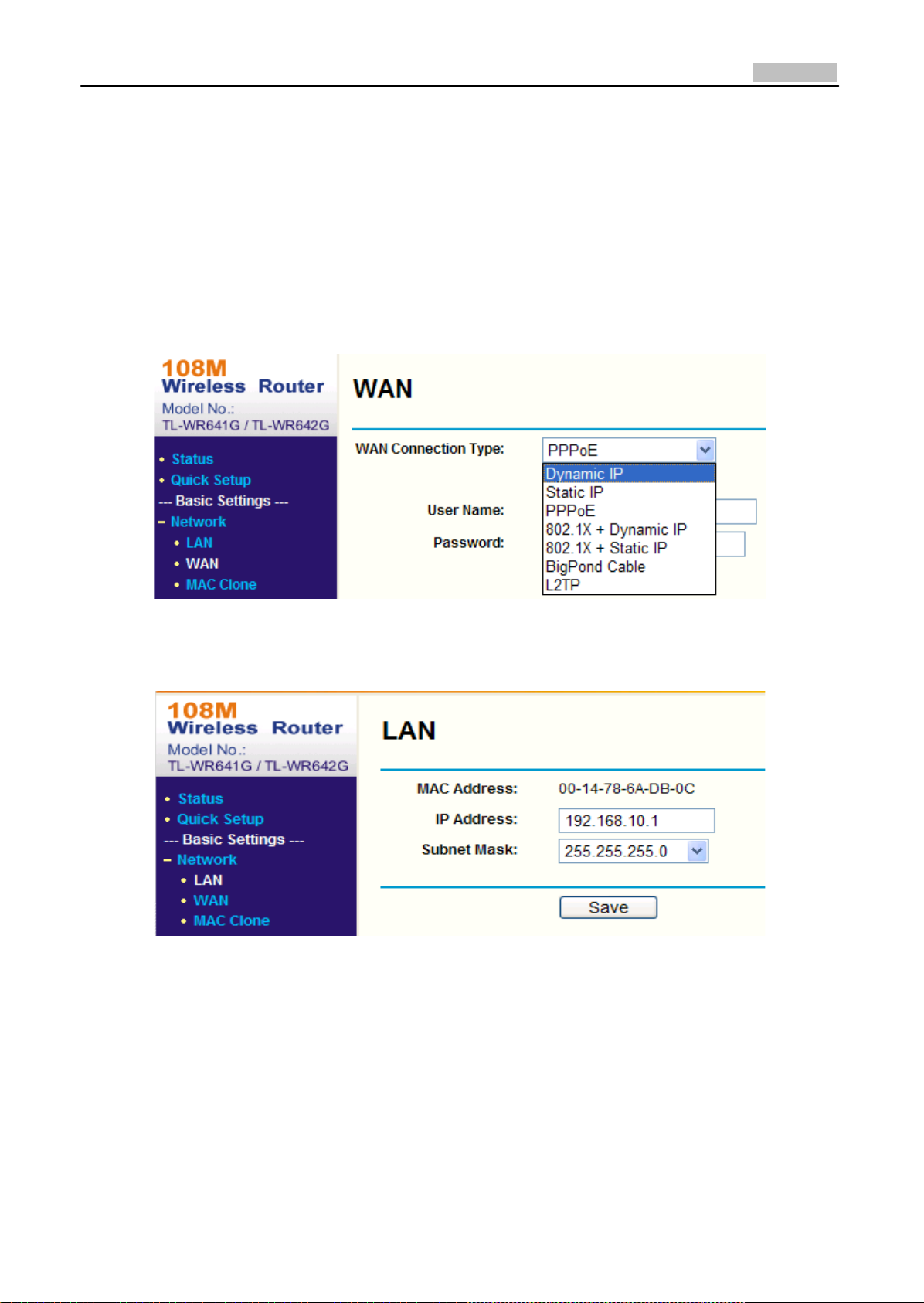
Appendix 2 Port Map
Note: The following setting is about TP‐LINK router (TL‐R410), which is maybe distinct from other
router’s setting.
1. Firstly, select the router’s WAN connection Type. As the following Fig. shows:
2. Set the “network parameter” of the router as the below figure. The setting includes subnet
mask and gateway.
3. Set the port map in the virtual severs of Forwarding. By default, camera uses port 80, 8000, 554
and 8200. You can change these ports value with IE or client software.
The following figure gives the illustration. One camera’s ports are 80, 8000, 554, 8200 and its IP
address is 192.168.1.23. The other camera’s ports are 81, 8001, 555, 8201 and IP is 192.168.1.24.
Afterwards, enable all or TCP protocols. Enable the port map after pressing the ‘Save’.

31
User Manual of Network Camera
As the settings mentioned above, map the router’s port 80 and 8000 to the network camera at
192.168.1.23; and port 81 and 8001 to the network camera at 192.168.1.24. In this way, user can
access the 192.168.1.23 through accessing the router’s port 80 and 8000.
Note: The port of the network camera cannot conflict with other ports. For example, some router’s
web management port is 80. User can amend the router’s or the camera’s port to solve this
problem.

32
User Manual of Network Camera
Appendix 3 Pin Definition
(1)UTP between the network port of camera and HUB (Direct Cable)
(2)UTP between the network port of camera and PC (Cross Cable):
 Loading...