

Page 1

1
Integrated Intelligent Video Surveillance
Management System
User's Manual
Page 2

2
Contents
1. Product Description .............................................................................................................................. 4
1.1. General Information ................................................................................................................ 4
1.2. System Topology ...................................................................................................................... 5
1.3. Operating Environment ........................................................................................................... 5
1.4. Operation Flow ......................................................................................................................... 5
1.4.1. Setup ............................................................................................................................... 6
1.4.2.Configuration ................................................................................................................... 7
1.4.3. Usage .............................................................................................................................. 8
2. Platform Manager ................................................................................................................................. 8
3. Software Introduction ........................................................................................................................... 8
3.1. Video Preview................................................................................................................... 9
3.1.1 Enable Preview ................................................................................................................ 9
3.1.2 Right Click Options ....................................................................................................... 11
3.1.3 Right Click of Channel Window ................................................................................... 12
3.1.4 Electronic Preview Zooming ......................................................................................... 13
3.1.5 Device Group Preview ................................................................................................... 14
3.1.6 PTZs (Pan/Tilt/Zoom) and Auxiliary ............................................................................ 16
3.2. Video Playback ....................................................................................................................... 20
3.2.1 Record Search .............................................................................................................. 200
3.2.2 Record Playback ............................................................................................................ 21
3.2.3 Right Click of Playback Channel................................................................................... 22
3.2.4 Clipping of Recording Files ........................................................................................... 22
3.2.5 Downloading of Recording Files ................................................................................... 22
3.2.6 File Management ........................................................................................................... 22
3.2.7 Capture .......................................................................................................................... 23
3.2.8 Partial Zoom-in of Playback Channel ............................................................................ 23
4. Electronic Map ........................................................................................................................... 24
4.1 Open & Close ................................................................................................................... 24
Page 3

3
4.2 Group Preview .................................................................................................................. 25
4.3 Zooming ........................................................................................................................... 26
4.4 Channel Preview ............................................................................................................... 26
4.5 Recording Playback .......................................................................................................... 27
4.6 PTZ Control ...................................................................................................................... 28
5. Operation Log ............................................................................................................................ 29
5.1 Alarm Log ........................................................................................................................ 29
5.2. Operation Log .................................................................................................................. 30
6. System Configuration ............................................................................................................... 31
7. Device Management .................................................................................................................. 32
7.1 New Area .......................................................................................................................... 33
7.2 Modify Area ..................................................................................................................... 33
7.3 Delete Area ................................................................................................ ....................... 33
7.4 New Device ...................................................................................................................... 35
7.5 Modify Device .................................................................................................................. 38
7.6 Delete Device ................................................................................................................... 39
7.7 Obtain STS Device Parameters......................................................................................... 39
7.8 Right Click Options .......................................................................................................... 42
8. User Management ..................................................................................................................... 42
8.1 New User .......................................................................................................................... 43
8.2 User Right ......................................................................................................................... 44
8.3 Modify User ...................................................................................................................... 45
8.4 Delete User ....................................................................................................................... 45
8.5 Modify Password (to modify the password of the currently registered user) ................... 45
9. Alarm Setting ............................................................................................................................. 46
9.1 Alarm Linkage Interface ................................................................................................... 46
9.2 New Linkage..................................................................................................................... 46
9.3 Delete Linkage .................................................................................................................. 51
9.4 Start Linkage..................................................................................................................... 51
9.5 Stop Linkage ..................................................................................................................... 51
Page 4

4
9.6 Refresh .............................................................................................................................. 51
10. Map Configuration .................................................................................................................. 51
10.1 Create Map ..................................................................................................................... 52
10.2 Open Map ....................................................................................................................... 53
10.3 Close Map ....................................................................................................................... 53
10.4 Modify Map .................................................................................................................... 53
10.5 Delete Map ..................................................................................................................... 54
10.6 Zooming ......................................................................................................................... 54
10.7 Arming of Video Source and Alarm Source ................................................................... 54
1. Product Description
1.1. General Information
1)Centralized management of common equipment in video monitor (including
DVR, DVS and IPCamera, etc.).
2) Through the platform of the client, provide a unified browsing interface to
view real-time images, search and playback history data.
3) Through to the key video data for intelligent video analysis, to detect,
identify, track, monitor targets in the scene movement, and intelligent behavior
analysis of moving targets, judge and predict the movement trajectory, in
violation of rules of behavior of target motion alarm, realize the active safety
monitoring area.
4) The front-end equipment alarm messages forwarded to the server, alarm
server control alarm devices, and do the corresponding alarm linkage, linkage
(110), such as sending mobile phone text messages, and sending e-mails, etc.
Page 5

5
CT
NVR
DVS
IPC
DVR
Setup
1.2. System Topology
1.3. Operating Environment
1) STS:
OS: Ubuntu9.1.0
CPU: Intel Pentium IV 2.0 GHz or higher
RAM: 1G or higher
Capacity: 64 or more ways of front-end videos supported depending on its
configuration
2) CT:
OS: Microsoft Windows 2000 or higher
CPU: Intel Pentium IV 2.0 GHz or higher
RAM: 1G or higher
Capacity: supported number of front-end devices is not limited, and 16 D1
or more ways of real-time video browsing supported
1.4. Operation Flow
The following figure shows the system operation flow:
Page 6

6
Matrix
Software Setup
Alarm settings
Add device
User management
Map configuration
Authorization
Database backup
System configuration
Enable service and authorization in the service
manager
Access the client terminal to configure it
Set features as required by a user
After all settings, back up the database
Operation log
Video playback
Video preview
Electronic map
Use the client
As required, choose to set up
the storage & transmission
server (STS) and decoder
server (DS)
As required, choose to add the
storage & transmission server
(STS) and decoder server (DS)
Setup
Configure
Usage
If unauthorized, each kind of device can be served by only
one set
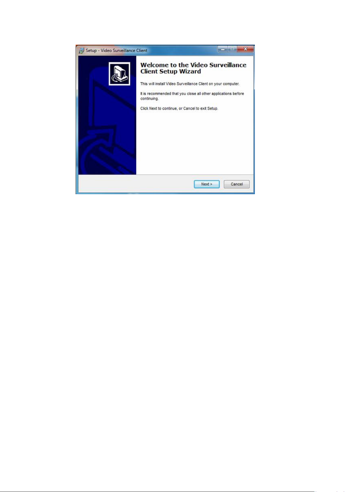
1.4.1 Setup
The system has professional and basic versions. The former supports storage and transmission as well
as decoding & post, which these are not supported for the latter. The following takes the professional
version as a setup example:
Page 7
7
Click the "Next" button by following up instructions till setup is
successful (Auto start is checked by default).
Note:
1. During setup, if anti-virus software gives a tip, choose to allow the program. After
successful setup, close firewall or add the service program to Exception List of the firewall.
2. If the program is to be updated or upgraded, uninstall the old version, and restart your
computer before installing the new one.
3. After successful installation of servers, the firewall should be closed to allow access
from the client.
1.4.2 Configuration
As indicated in the flowchart, after entering the platform client, add a
device firstly by referring to
Chapter 3, New Device in Device Management of Software Introduction, and
then set features of each module as required, such as alarm settings, user
management, map configuration and system configuration. After all features
are set, back up the database in the service manager. This feature is detailed in
each section of Software Introduction.
Page 8
8
1.4..3 Usage
Video preview, video playback, electronic map, matrix and operation log
are browsing modules. In the video playback module, record plan of central
office is configured in the device management. For details, see "STS
Parameter".
Note: please refer to corresponding feature configuration description for their detailed
operations. (TV wall module function is unavailable)
2. Platform Manager
(platform manager module function is unavailable)
3. Software Introduction
Main Screen
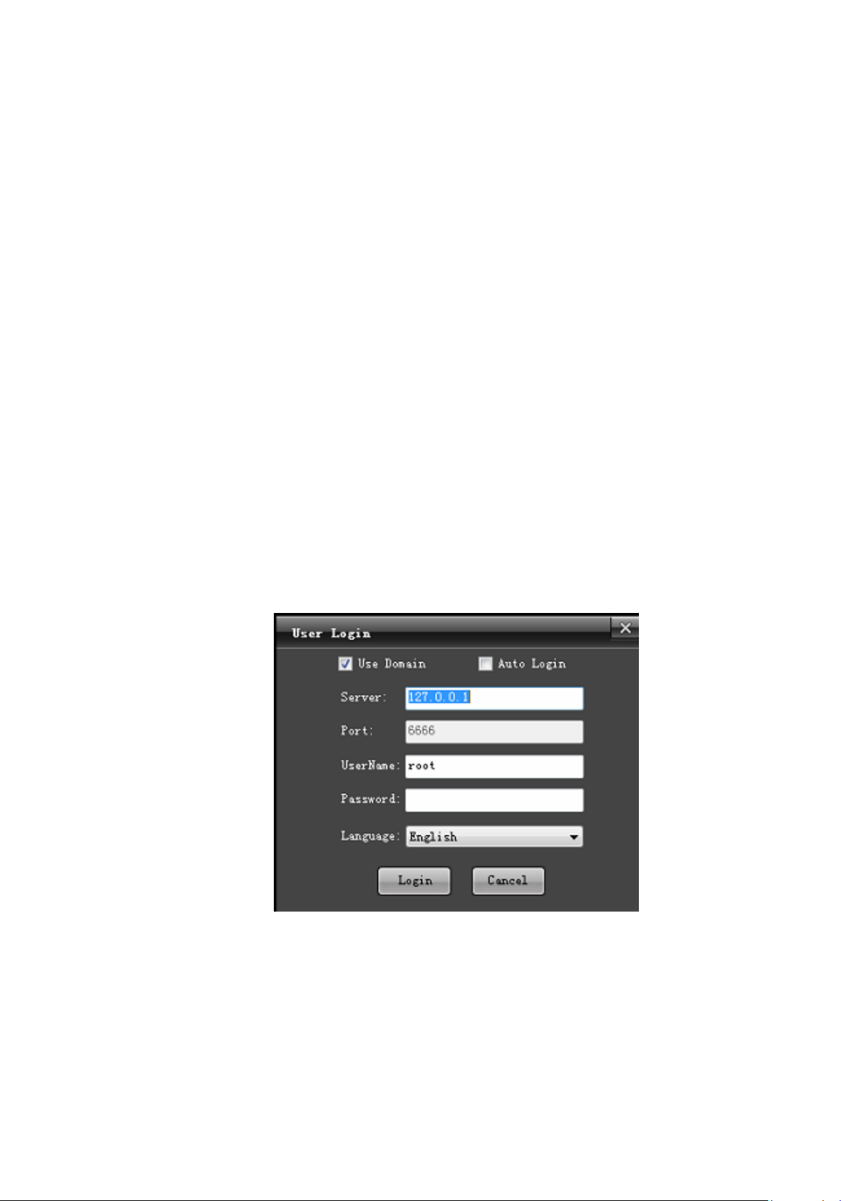
Login Screen
Server: IP address of the central server (127.0.0.1 is the machine IP).
User name and password: root, the password is empty by default and can
be edited in the device management.
Language: select a language for the client.
Page 9

9
Main screen is divided into 10 modules, as shown in the figure:
3.1. Video Preview
Enter the " Preview" functional module, as shown in the figure:
Note: the top right corner displays CPU usage
3.1.1 Enable Preview
In the left device list, double click or drag a channel to the window (right
click to show "enable all preview" function) to enable preview of device
channel (the icon with preview enabled will be accompanied with a triangle
icon, indicating that this channel is being previewed), as shown in the
Page 10

10
following figure:
Page 11

11
Record
Video signal
Green icon
√
√
Red icon
×
√
Yellow icon
√
×
Gray icon
×
×
Front-end record
Central office record
√
√
×
√
Not supported for front-end
devices
√
×
×
Note: Icons of device channels shows in four colors, green, red, yellow and gray, displaying
recording and video signal states respectively.
In the screen of channel preview, the icon in the bottom right corner displays state of channel
record.
States of channel enabling and recording are set in the system configuration.
3.1.2 Right Click Options
1) Voice intercom
Page 12

12
"Voice intercom" is used to realize listening and intercom functions
between the platform and device.
2) One-key arming/disarming
"One-key arming" and "one-key disarming" are for arming and disarming
device alarms.
3) Alarm output control
"Alarm output control" is used to view state of device alarm output.
4) Eliminate
"Eliminate" is to cancel alarm linkage triggered and enabled for the device.
5) All main code stream/sub code stream (auto switching of main and sub
code streams is not selected)
"Main code stream" and "sub code stream" are used to modify parameters
of code stream of channels.
6) Restart
"Restart" is used to restart front-end devices.
7) Close all previews
"Close all preview" is used to close all channels in the window for this
device.
3.1.3 Right Click of Channel Window
1) Close preview
"Close preview" is used to close selected channels.
2) Close all previews
"Close all preview" is used to close all channels in the preview window.
3) Full screen display
"Full screen display" (shortcut key: Esc) is used to display the preview
window in full screen.
4) Capture
Page 13

13
"Capture" (capture button in the preview control) is used to capture
the preview screen in real-time, which will then be stored to the designated
directory, as shown in the following figure:
5) Audio preview
"Audio preview" is used to enable audio listening for the selected channel
(in the video preview window, only audio for one channel is enabled).
6) Instant replay
"Instant replay" is used to replay video recording recorded a short time ago
for this channel.
Note: the time for instant replay is set in "system configuration". For details, see "System
Configuration" section.
7) Screen mode
"Screen mode" is used to display the preview screen in 4:6, 16:9 or tile
mode.
3.1.4 Electronic Preview Zooming
Select a channel window, and scroll the mouse wheel to electronically
zoom in or out the channel, as shown in the following figure:
Page 14

14
(Note: after a channel is zoomed in, the screen can be dragged)
3.1.5 Device Group Preview
Firstly enter the "System Configuration" module, and then click "Device
Group" button to divide devices into several groups, as shown in the following
figure:
Page 15

15
1) In the group list, right click "New Group" to add a group;
2) In the group list, right click "Delete Group" to delete a group;
3) For a channel already in a group list, right click "Modify Cycle Time"
to change the cycle time for this channel;
4) In the channel list, select a channel to be added, set the cycle time, and
then select a group and click to add the channel to the designated
group;
5) In the group list, select a channel to be deleted, and click to
delete this channel;
6) Sort channels in the group by moving up or moving
down .
After a group is added, set the cycle mode.
Intra-group cycle: enter the video group module, and directly drag a group
to a channel, and enable cycle preview, as shown in the
following figure:
Page 16

16
Inter-group cycle (only for multiple groups): enter the video group
module, click to enable inter-group cycle, as shown in the following
figure:
"Enable All " and "Close All " displayed by right clicking a group are
used for enabling and closing all channels respectively in this group (all
preview and group cannot be simultaneously enabled).
Note: a group enabling cycle function will be accompanied with a label after its group icon,
such as .
3.1.6 PTZs (Pan/Tilt/Zoom) and Auxiliary
Preview Control
The control camera has 8 directions, including up, down, left, right, top
left, bottom left, top right and bottom right; zooming of focal length; zooming
of focus; zooming of aperture; setting of PTZ speed, as shown in the following
figure:
Page 17

17
Under the PTZ control panel, you can set color, brightness and contrast for
the selected channel, as shown in the following figure:
Under the color palette is some functional preview icons from the first one:
enabling video group cycle, back (the currently previewed channel is switched
to the previous channel of the same device), next (the currently previewed
channel is switched to the next channel), pausing video group cycle, eliminate
and capture.
Page 18

18
The following icon is an option whether the alarm linkage preview
responds.
The following is "Split Screen" button, allowing switching of 1, 4, 6, 8, 9,
10, 13, 16, 36 and 64 screens, as shown in the following figure:
Auxiliary Control
On the Aux Control panel, you can set and call presets, cruise, auxiliaries
and track, as well as setting of platform protocol:
(1) Setting and calling of presets: rotate the camera to the desired location
where the preset location will be set, click setting button, input preset
name and click "Save". If it is to change the preset location, rotate the camera
to the desired location and click button again and save data, and the preset
name will be updated. Up to 128 preset names can be set. Click call
button in the right side, allowing the camera directly to rotate to the related
preset location.
(2) Setting and calling of cruise: select a cruise number and click setting
button, and the cruise point setting dialog box pops up, as shown in the
Page 19

19
following figure, where you can input cruise name, select preset number, and
set cruise speed and residence time. Clicking "New Cruise" can add several
preset points to a cruise point. Up to 128 cruise paths can be set. Clicking
"Clear All" can delete all added preset points. Click call button to enable
cruise calling and click to close cruise.
(3) Setting and calling of track: From the dropdown menu, select a track
number, and click button to set the track memory. Rotate PTZ to set the
moving track of the camera, and then click again to close track memory
setting; click call button to start track and click to close track.
(4) Setting and calling of auxiliary: From the dropdown menu of auxiliary
setting, select the desired option and click to call it and click to close
auxiliary.
Page 20

20
(5) Setting of platform protocol: in the platform protocol, you can select
related protocol and address.
3.2. Video Playback
Enter the "Video Playback" functional module, as shown in the figure:
3.2.1 Record Search
In the left device tree, check the device channel to be played back (note:
max. 4 channels can be selected at a time), as shown in the following figure:
In "Condition Search" column, select the location and type to be played
Page 21

21
back, and select date from the calendar, and then click "Search" button, the
system will start to search records, and display results on the result panel, as
shown in the following figure:
3.2.2 Record Playback
is play button, is pause button and is stop button.
Selecting "Speed" adjusting scale can play all video recordings in a lower or
higher speed; Double clicking progress bar can play on demand, as shown in
the following figure:
Page 22

22
On the playback interface, double clicking a playback channel can play
the channel in full screen (press Esc to display the playback window in full
screen).
3.2.3 Right Click of Playback Channel
1) Increase or reduce channel contrast.
2) Increase or reduce channel brightness.
3) Open audio of the playback channel (only one audio for 4 playback
channels)
4) Optional 4:3, 16:9 or tile screen mode.
3.2.4 Clipping of Recording Files
Select a playback channel to be edited and click clipping button to
enable the clipping function; click clipping button again to stop clipping.
Note: (clipped video files are stored in D:\PlatData\VideoClip folder by default)
3.2.5 Downloading of Recording Files
Click download button to display video download setting screen, as
shown in the following figure:
Page 23

23
Select channels to be downloaded and their time intervals, and click
"start". Downloaded files are stored in the designated path.
Note: (Downloading is possible only when playback channels are closed, and downloaded
video files are stored in D:\PlatData\VideoDownLoad folder by default)
3.2.6 File Management
Click file management button to display the video file player
window, as shown in the following figure:
In the window, click "File" --> "Open" and locate downloaded MP4 files
in the video downloading path and add them to the right list. Double click to
play them.
3.2.7 Capture
In the playback window, selected a playback channel, and click
Page 24

24
capture button, all captured images are stored in the designated folder.
Note: (all captured images are stored in D:\PlatData\Capture folder by default)
3.2.8 Partial Zoom-in of Playback Channel
In the playback screen, select a channel to be zoomed in, and scroll the
mouse wheel to electronically zoom in or out the channel, as shown in the
following figure:
Note: after a channel is zoomed in, the screen can be dragged.
Select a playback channel and press "Esc" to play the channel in full screen.
4. Electronic Map
Enter the "Electronic Map" functional module, as shown in the figure:
Page 25

25
4.1 Open & Close
Double click the map icon in your region, or select its icon, and right click
to select "open map", as shown in the following figure:
Click close button, or select the icon, and right click to select "close
map".
Page 26

26
4.2 Group Preview
Click map channel group preview button to implement group video
preview of all armed channels in the map, as shown in the following figure:
4.3 Zooming
Click zoom-in button to zoom in the electronic map; click
zoom-out button to zoom out the electronic map (map can also be zoomed in or
out by scrolling the mouse wheel).
4.4 Channel Preview
Open a map with "Video Channel" armed, select a "Video Channel" and
right click "Channel Preview" to preview the video channel in real-time, as
shown in the following figure:
Page 27

27
Page 28

28
4.5 Recording Playback
Select "Recording Playback" to playback a channel, as shown in the
following figure:
4.6 PTZ Control
Select "PTZ Control" to control the PTZ, as shown in the following
figure:
Page 29

29
5. Operation Log
Enter the "Operation Log" functional module, as shown in the figure:
5.1 Alarm Log
Input alarm conditions to be searched in the "Search Condition" column,
as shown in the following figure:
Page 30

30
Click "Search" (only operation logs in last 7 days can be searched), as
shown in the following figure:
5.2. Operation Log
Input alarm conditions to be searched in the "Search Condition" column,
as shown in the following figure:
Click "Search", as shown in the following figure:
Page 31

31
6. System Configuration
Enter the "System Configuration" functional module, as shown in the
figure:
Page 32

32
1) In the "System Configuration" screen, you can set paths for "captured
image", "video clipping" and "video downloading".
2) Set the time to enable screen saver.
3) Preview time of preview and prerecord (real-time playback).
4) Device group setting.
5) Auto login setting (skip the login interface to enter the system).
6) Auto enabling of the preview window (video preview module is
automatically enabled after entering the system).
7) Setting of channel operating state.
8) Auto switching of main and sub code streams (single-screen full screen
is automatically switched to main code stream and multi-screen split screen is
automatically switched to sub code stream).
9) Setting of cycle preview mode (intra-group cycle and inter-group cycle).
7. Device Management
Page 33

33
Enter the "Device Management" functional module, as shown in the
figure:
7.1 New Area
In the left list, select an area (area is cms=0 by default), and right click to
select "New Area", as shown in the following figure:
Page 34

34
In the "Area Management" page, input area name and click "Save". The
area is added successfully, as shown in the following figure:
Page 35

35
7.2 Modify Area
In the left list, select an area to be modified, and right click to select
"Modify Area" to modify it.
7.3 Delete Area
In the left list, select an area to be deleted, and right click to select "Delete
Area". The area is deleted successfully (when this area has sub-areas or
devices, this area cannot be deleted).
7.4 New Device
Select an area to be added with device, and click "New Device" (or in this
area, right click to select "New Device"), and click device information, as
shown in the following figure:
Page 36

36
Click "Save". The device is added successfully.
In device type, some device types can be searched, as shown in the
following figure:
Page 37

37
Click to open the search list, and click search to display all devices of this
type in the LAN. In the list, you can modify user name and password, as shown
in the following figure:
Page 38

38
You can choose to select a device or add in batch (MultiAdd Dev). The
"Select" action selects one device at a time, and saves it and then adds other
devices; the "MutiAdd Dev" action can check multiple devices and click
"MutiAdd Dev" to add them to the client.
7.5 Modify Device
In the device list, select a device to be modified, and click "Modify
Device". Then input information and save it, as shown in the following figure:
Page 39

39
7.6 Delete Device
In the device list, select a device to be deleted, click "Delete Device" (or
in the left device tree, select a device to be deleted, and right click to select
"Delete Device") to delete it.
7.7 Obtain STS Device Parameters
7.7.1 Device Parameter Setting
In the left device tree, select STS device, and right click "Device
Parameter", as shown in the following figure:
Page 40

40
Note: device parameters can be obtained only when the STS device is online.
7.7.2 Storage Setting
Note: able to select multiple disks at a time (reserved space is not less than 1024 MB).
7.7.3 Static Route Setting
Page 41

41
Click "New Route" to check devices to be added (DVR, DVS) and click
"Save", as shown in the following figure:
Note: the static route should be set before adding record plan.
"Delete Route": check devices to be deleted (DVR, DVS) and click
"Delete Route".
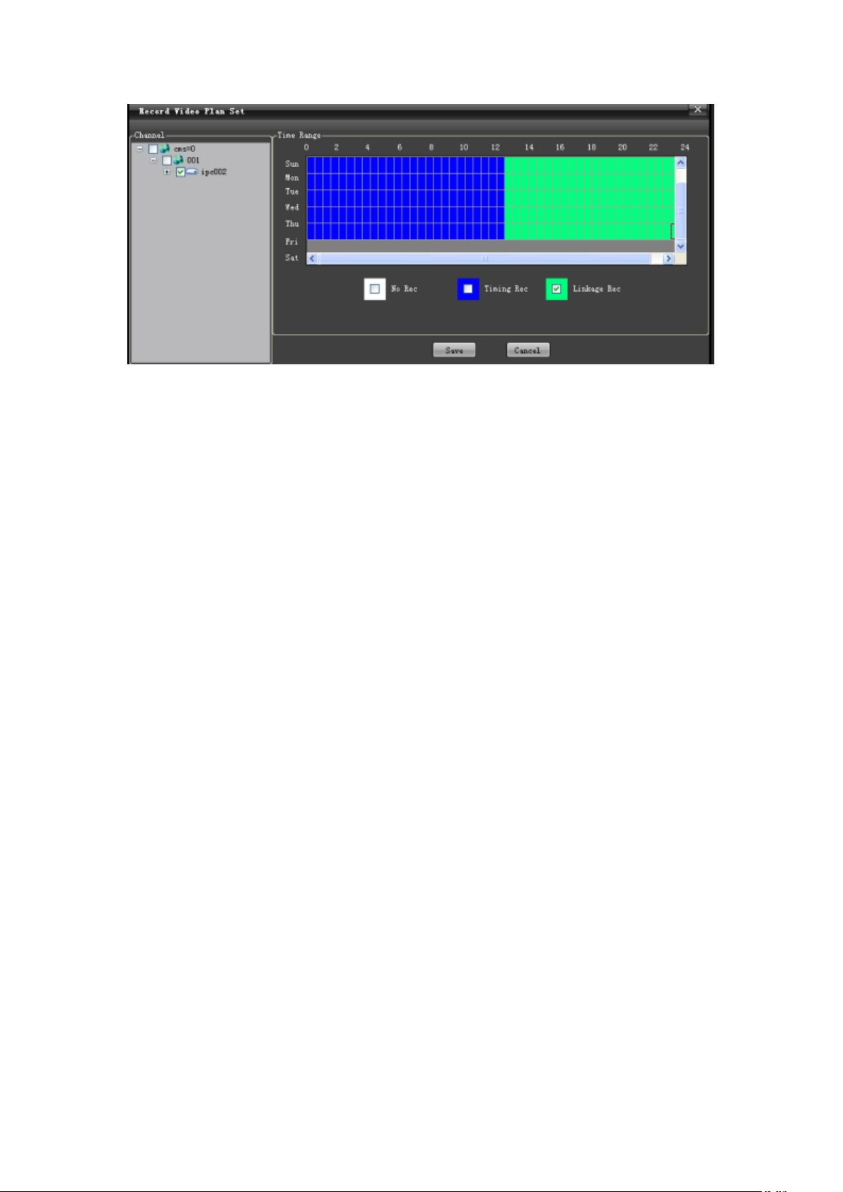
7.7.4 Record Plan
Click "New Plan" to enter the record play editing page. In the left device
tree, check device channel to be recorded, and in the bottom right, check the
record type, then use your mouse to select Time Range, and then click
"Save", as shown in the following figure:
Page 42
42
"Delete Plan": check record plan channel to be deleted from the list and
click "Delete Plan".
"Start Plan": check record plan channel to be started from the list and click
"Start Plan".
"Stop Plan": check record plan channel to be stopped from the list and
click "Stop Plan".
7.7.5 Record Status
"Record Status" can reflect whether record plan for the storage server is
enabled in real-time.
7.7.6 Device Refresh
"Device Refresh" allows refreshing real-time status and information of
devices in the list.
7.8 Right Click Options
In the right click menu, there are three options including "Device
Parameter", "Edit Channel" and "Delete Channel":
"Device Parameter" is used to call the device parameter setting page out.
"Edit Channel" is used to modify the name of device channel.
"Delete Device" is used to directly delete selected device.
8. User Management
Enter the "User Management" functional module, as shown in the figure:
Page 43

43
8.1 New User
Click "New User" and input user information, as shown in the following
figure:
Note: In the "User Type" and "Belong Area" columns, select the user type and area range
you will assign.
Level-to-level administration for users is implemented in following rules:
1. Administrator, visible to all users in this user area.
2. An administrator can create, view, modify and delete general users at the same level
Page 44

44
or the lower level, and can only create, modify and delete administrators at the lower level.
3. Root is a super administrator owning the right to add, view, modify and delete all
users
(Any information except password for the root user cannot be modified).
8.2 User Right
In "Right Control", a new user can be assigned with specified rights, as
shown in the following figure:
Note: for a right option with drop down menu, right assignment can be designated to
device channel.
Click "Save" to successfully add a user, who can be viewed in the user
list, as shown in the following figure:
Page 45

45
8.3 Modify User
In the user list, select a user to be modified, and click "Modify User".
Then input information and save it, as shown in the following figure:
8.4 Delete User
In the user list, select a user to be deleted and click "Delete User" to delete
it.
8.5 Modify Password (to modify the password of the currently
Page 46

46
registered user)
In the user list, select a current registered user, and click "Modify
Password". Then input information and save it, as shown in the following
figure:
9. Alarm Setting
9.1 Alarm Linkage Interface
Enter the "Alarm Setting" functional module, as shown in the figure:
9.2 New Linkage
9.2.1 Alarm Input
Input the linkage name, and select "Alarm Input". From the dropdown
menu, select an "Event Source", as shown in the following figure:
Page 47

47
If "Preview" is selected for the Linkage Action, select one or more linkage
channels from the dropdown menu, a nd the "Action Para." box will show all
added linkage information, as shown in the following figure:
If "PTZ Linkage" is selected for the Linkage Action, select one or more
Page 48

48
linkage channels from the left "Video Channel" of the dropdown menu. In the
left "PTZ Linkage" option, select one linkage action (Turn to preset, start track
and start cruising), as shown in the following figure:
If "Rec Video" is selected for Linkage Action, check the record channel in
STS device from the left "Video Channel" list of the dropdown menu, as shown
in the following figure:
Page 49

49
If "Alarm Output" is selected for Linkage Action, select one or more
"Alarm Device" from the left "Linkage Alarm Output" of the dropdown list, as
shown in the following figure:
Page 50

50
After settings, click "Save" to successfully add alarms, as shown in the
following figure:
Note: When selecting linkage action, "Auto" indicates that linkage starts when an alarm generates, and
vice versa and record stops; "Time" indicates that alarm linkage stops within the set time; "Manual"
indicates that linkage is manually stopped.
9.2.2 Motion Detection Alarm
For operation procedures of "Motion Detection Alarm", see instructions in
the "Alarm Input" section.
9.2.3 Video Covering Alarm
For operation procedures of "Video Covering Alarm", see instructions in
the "Alarm Input" section.
9.2.4 Video Loss Alarm
For operation procedures of "Video Loss Alarm", see instructions in the
"Alarm Input" section.
9.3 Delete Linkage
In the alarm information list, select an alarm type to be deleted, and click
"Delete Linkage", and this alarm information will be removed from the
information list.
9.4 Start Linkage
Page 51

51
In the alarm information list, select an alarm type to be started and click
"Start Linkage" to start it.
9.5 Stop Linkage
In the alarm information list, select an alarm type to be stopped and click
"Stop Linkage" to stop it.
9.6 Refresh
Click "Refresh" to refresh current alarm information list.
10. Map Configuration
Enter the "Map Configuration" functional module, as shown in the figure:
10.1 Create Map
Page 52

52
In the left information box of "Map Config", select an area and right click
the "Create Map" and input map information. Click "Save", as shown in the
following figure:
10.2 Open Map
Double click the map icon or select its icon, and right click to select
"Open Map", as shown in the following figure:
Page 53

53
10.3 Close Map
Click close button, or select the icon, and right click to select "Close
Map".
10.4 Modify Map
Select a map, and right click to select "Modify Map" and input
information and save it, as shown in the following figure:
10.5 Delete Map
Page 54

54
Select a map and right click to select "Delete Map" to delete it.
10.6 Zooming
Click zoom-in button to zoom the electronic map in and click
zoom-out button to zoom it out.
10.7 Arming of Video Source and Alarm Source
Drag and drop the "Surveillance Channel" and "Alarm Channel" in the left
"Device Information" list in the main screen to the right map for arming. The
map allows arming multiple channels and alarm inputs, as shown in the
following figure:
Select "Surveillance Channel" or "Alarm Channel" armed in the map and
right click to select "Remove Channel" to delete armed video and alarm
channels ("Remove all" can remove all channels), as shown in the following
figure:
Page 55

55
"Modify Icon": allow you to modify the icon as you like for easy
application, as shown in the following figure:
Page 56

56
 Loading...