

Page 1

XL-GDB-102Ev2
G.SHDSL .Bis
User Manual
Version 0.03
Page 2

Tables of
Contents
1.
INTRODUCTION
...............................................................................................................................
3
1.1
F
EATURES
........................................................................................................................................
4
1.2
SPECIFICATION ..................................................................................................................................
4
1.3
A
PPLI
CATIONS
................................................................................................................................... 6
2.
GETTING TO KNOW ABOUT THE XL-GDB102E ..............................................................................
7
2.1
FRONT PANEL ...................................................................................................................................
7
2.1.1.
E1 interface mode
l
................................................................................................................... 7
2.1.2.
Serial interface mode
l
.............................................................................................................. 7
2.1.3.
Ethernet interface model
......................................................................................................... 7
2.1.4.
Three interface in
one mode
l
................................................................................................... 7
2.2
R
EAR PANEL
...................................................................................................................................
10
2.2.1.
E1 Interface
Model
................................................................................................................
10
2.2.2.
Serial (V.35) Interface
Model
.................................................................................................
11
2.2.3.
Ethernet Interface
Model....................................................................................................... 12
2.2.4.
Three interface in
one
Model................................................................................................. 13
2.3
I
NSTALLATION
.................................................................................................................................
14
2.3.1.
E1
Interface
............................................................................................................................ 15
2.3.2.
V35 Interfac
e
......................................................................................................................... 15
2.3.3.
Ethernet Interface
.................................................................................................................. 16
3.
CONFIGURATION WITH
KEYPAD AND LCD......................................................................................
17
3.1
K
EY PADS
.......................................................................................................................................
17
3.2
MAIN MENU
T
REE
...........................................................................................................................
18
3.3
M
ENU TREE FOR
SHOW STATUS
...................................................................................................... 19
3.4
M
ENU TREE FOR
SHOW
S
TATISTICS
................................................................................................. 21
3.4.1.
Show Statistic on
E1 Interfac
e
............................................................................................... 22
1
Page 3

3.4.2.
Show Statistic on
Serial (V.35) Interfac
e
................................................................................ 23
3.4.3.
Show Statistic on Etherne
t
Interface
...................................................................................... 24
3.5
M
ENU TREE FOR
SYSTEM SETU
P
..................................................................................................... 25
3.5.1.
Sub-Menu tree for
SETUP SHDSL ...........................................................................................
26
3.5.2.
Sub-Menu tree for
SETUP E1 Interfac
e
.................................................................................. 27
3.5.3.
Sub-Menu tree for
SETUP SERIES
Interface
............................................................................ 31
3.5.4.
Sub-menu tree for
SETUP Ethernet Interfac
e
......................................................................... 33
3.6
SUB-
MENU TREE FOR
REBOOT SYSTE
M
............................................................................................ 38
3.7
SUB-M
ENU TREE FOR
DISGNOSTIC ..................................................................................................
39
3.7.1.
L
oopback function
................................................................................................................. 39
2
Page 4

3.7.2.
BER Test functi
on
................................................................................................................... 42
4.
CONFIGURATION WITH CONSOLE
PORT
........................................................................................
43
4.1
L
OGIN PROCEDURE
..........................................................................................................................
43
4.2
W
INDOW STRUCTURE
......................................................................................................................44
4.3
MAIN MENU
S
UMMAR
Y
...................................................................................................................
46
4.4
C
ONFIGURATION
.............................................................................................................................
47
4.4.1.
Configure
NTU Interfac
e
........................................................................................................ 48
4.4.2.
Configure
SHDSL
parameters................................................................................................. 49
4.4.3.
Configure
E1
parameters
....................................................................................................... 52
4.4.4.
Configure
Serial
parameters
.................................................................................................. 59
4.4.5.
Configure Etherne
t
parameter............................................................................................... 63
4.4.6.
Remote confi
guration
............................................................................................................ 66
4.4.7.
Restore factory defaul
t
.......................................................................................................... 66
4.5
R
EBOOT
........................................................................................................................................
67
4.6
VIEW THE
SYSTEM STATUS
.................................................................................................................
68
4.7
V
IEW THE STATISTIC
.........................................................................................................................
70
4.8
V
IEW SYSTEM CONFIGURATIO
N
..........................................................................................................
75
4.9
U
PGRADE
......................................................................................................................................
82
4.10
D
IAGNOSTIC
...................................................................................................................................
86
4.11
E
XIT
..............................................................................................................................................
91
5.
APPENDIX ......................................................................................................................................
93
5.1
A
BBREVIATIO
N
................................................................................................................................ 93
5.2
C
ONSOLE CABL
E
..............................................................................................................................
96
5.3
S
ERIAL INTERFACE PIN ASSIGNMENTS
..................................................................................................
97
5.4
DB25(M) VS.
M.34(M)
C
ABLE ........................................................................................................
98
5.5
E1 C
ABLE
......................................................................................................................................
99
5.6
DSL C
ABLE
....................................................................................................................................
99
3
Page 5

1. Introduction
The G.XL-GDB102E offers three different interface (E1, Serial and Ethernet) connected
customers to high-speed TDM services .This series have four models on the following:-
E1 interface model :
Offers two different ways have connect customers to high-speed TDM services with two G.703
E1 interfaces (Balance 120Ω RJ45 jack and Unbalance 75Ω dual BNCs). The G.703 interface will
carry 64kbps to 2.048Mbps.
Serial (V.35) interface model:
Offers customers premises has high-speed TDM services with a DB25 interface. The industry
standard DB25 interface can be configured as a V.35/RS530 or V.36/X.21 connection. The
DB25 connection transfers data up to 5.696Mbps.
Ethernet interface model:
Offers customers premises has high-speed TDM services with a LAN interface. The
industry standard LAN interface can detect a 10M or 100M connection automatically.
Three interface (E1, Serial and Ethernet) in one model:
Offers three types interface: E1 interface (balance 120Ω RJ45 jack and unbalance 75Ω dual
BNCs), V.35 interface (DB25 female connector) and Ethernet interface (RJ-45 connector).You
can select one type of following: (a) E1 interface only (b)V.35 interface only (c) Ethernet interface
only (d) E1 and V.35 interface (e)E1 and Ethernet interface.
They can be configured and managed via EOC, or menu-driven VT100 compatible Asynchronous
Terminal Interface, either locally or remotely.
The G.XL-GDB102E is equipped with an auto rate capability that identifies the maximum line rate
supported by the copper loop. This powerful automatic configuration capability makes installation
and service provisioning simple and painless. Further flexibility is provided in the ability to
manually set the maximum NTU speed at different levels for different customer-tailored service
offerings.
4
Page 6

1
.1 F ea t ur e s
Standard G.shdsl .Bis ITU G.991.2 (2004) supports improved reach/speed and
greater interoperability
Fast and cost-effective provisioning of traditional frame relay (FR or T-HDLC) or TDM
leased line services
User existing copper loop infrastructures
Can operate back to back connection
Efficient single wire pair usage
Up to 5.696Mbps symmetric service bit rate
Auto rate installation maximizes data rate based on loop conditions
Auto configuration wetting current to protect SHDSL line
Local management interface with LCD display
Remote line loopback
SHDSL Line performance monitoring (Data Rate and SNR)
Raw and per time interval statistics
Bandwidth guaranteed transmission equipment
Remote firmware upgrade
1
.2 S pe c ifica tion
WAN Interface
• Line Rate: ITU G.991.2(2004)
• Coding: trellis coded pulse amplitude modulation (TC-PAM16 and TC-PAM32)
• Support: Annex A ,B , F and G
• Payload rates: 192kbps to 5.696Mbps (N x 64kbps N=3 to 89)
• Connection: RJ-45 jack (2-wire)
• Impedance: 135 ohms
G.703 Interface (as E1)
• Connection: RJ-45 for balanced 120Ω E1 cable
• Connection: BNC for unbalanced 75Ω E1 cable
• Line Rate : 2048KHz +/- 50ppm
• Framing : PCM30/30C/31/31C and Unframed
• Data Rate : 64Kbps to 2.048Mbps ( Nx64Kbps , N=1 to 32)
• Operation : Full E1 and Fractional E1
DTE Interface ( as V.35)
• Payload rates: Up to 5.696Mbps
• Support V.35/RS-530 or V.36/X.21
5
Page 7

LAN Interface ( as Ethernet)
• Single Ethernet Interface
• 10/100Mpbs Half/Full Duplex, Auto-sensing, Auto-Crossover
• Up to 1024 MAC address learning, filtering bridge
DSL Timing
• Internal
• From E1 Recovery (as E1)
• From DTE ( as V.35 and Ethernet)
Performance Monitoring
• ES, SES, UAS, Alarms, Errors
Loopback Tests ( for E1 and V.35 interface only)
• Local Loopback
• Digital Loopback
• Remote Loopback
• Far-end Loobpack
• Build-in 2047 bit tester
Management
• Configuration with keypad and LCD display
• Console port (RJ45 , RS232C)
• Support firmware upgradeable
Physical/Electrical
• Dimensions: 19.8 x 4.6 x 16.8 cm
• Input: 90~240VAC with 50~60Hz
• Power Consumption: 10W Max
• Operation temperature: 0 to 50°
C
• Humidity: Up to 95% (non-condensing)
• External screw for frame grounding
6
Page 8

1
.3 A pp lic a ti o n s
7
Page 9
2. Getting to know about the XL-GDB102E
This chapter shows the front and rear panel and how to install the hardware.
2
.1 F ro n t P an e l
2.1.1. E1 interface model
2.1.2. Serial interface model
2.1.3. Ethernet interface model
2.1.4. Three interface in one model
8
Page 10

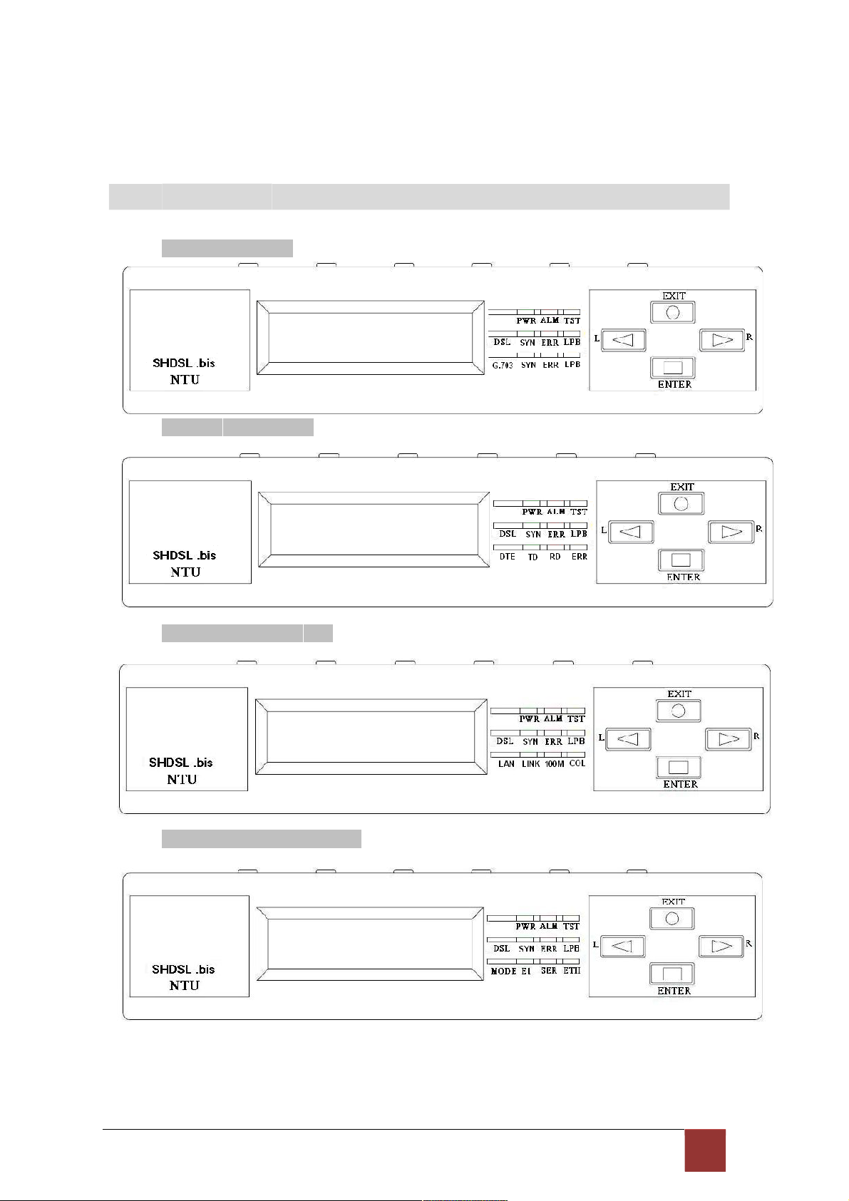
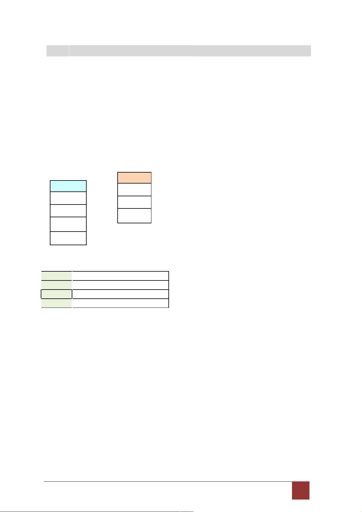
Front panel can be separated into three parts: LCD display, LED indicator and Keypads.
The LCD display can show the status and configuration of device. The local management
interface will be done by keypads with this LCD display.
The purpose of key pads is to configure the setting or selecting of function on this
NTU. The following table describes the LEDs’ function of device.
PWR
ALM
TST
SHDSL
LED
SYN Green
ERR Red
LPB Yellow
Color Action
On
Green
Red
Yellow
Off
On
Off
On
Off
On
Blink Data transmit in SHDSL line.
Off
Blink Error second occurs.
Off
On
Off
Description
Power is on.
Power is off.
System loss.
System is working nomarally.
System is testing for connection.
System is working nomarlly.
SHDSL line is connected.
SHDSL line is dropped.
No error second.
Loopback is on.
Loopback is off.
E1
V.35
ETH
SYN Green
ERR Red
LPB Yellow
TD
RD
ERR Red
LINK Green
Green
Green
On
E1 line is connected.
Off
E1 line is dropped.
Blink There are error seconds.
Off
There is not any error second.
On
Loopback is on.
Off
Loopback is off.
On
Data transmit in V.35.
Off
No data transmit in V.35.
On
Data receive in V.35.
Off
No data reveive in V.35.
Blink Error second occurs.
Off
No error second.
On
Data transmit in Ethernet.
Off
No data transmit in Ethernet.
9
Page 11

100M Green
On
Data receive in 100M.
Off
No data receive in 100M.
COL Red
Blink Error collision occurs.
Off
No error collision.
Mode E1 Green Blink E1 Data tramsmit and receive
On
E1 cable cable connected
Red
On
No E1 cable connected
SER Green Blink Serial Data tramsmit and receive
On
DTE Connected
Red
On
DTE Disconnect
ETH Green Blink Ethernet Data tramsmit and receive
On
Ethernet cable connected
Red
On
No Ethernet cable connected
9
Page 12
2
.2 R ea r P a ne l
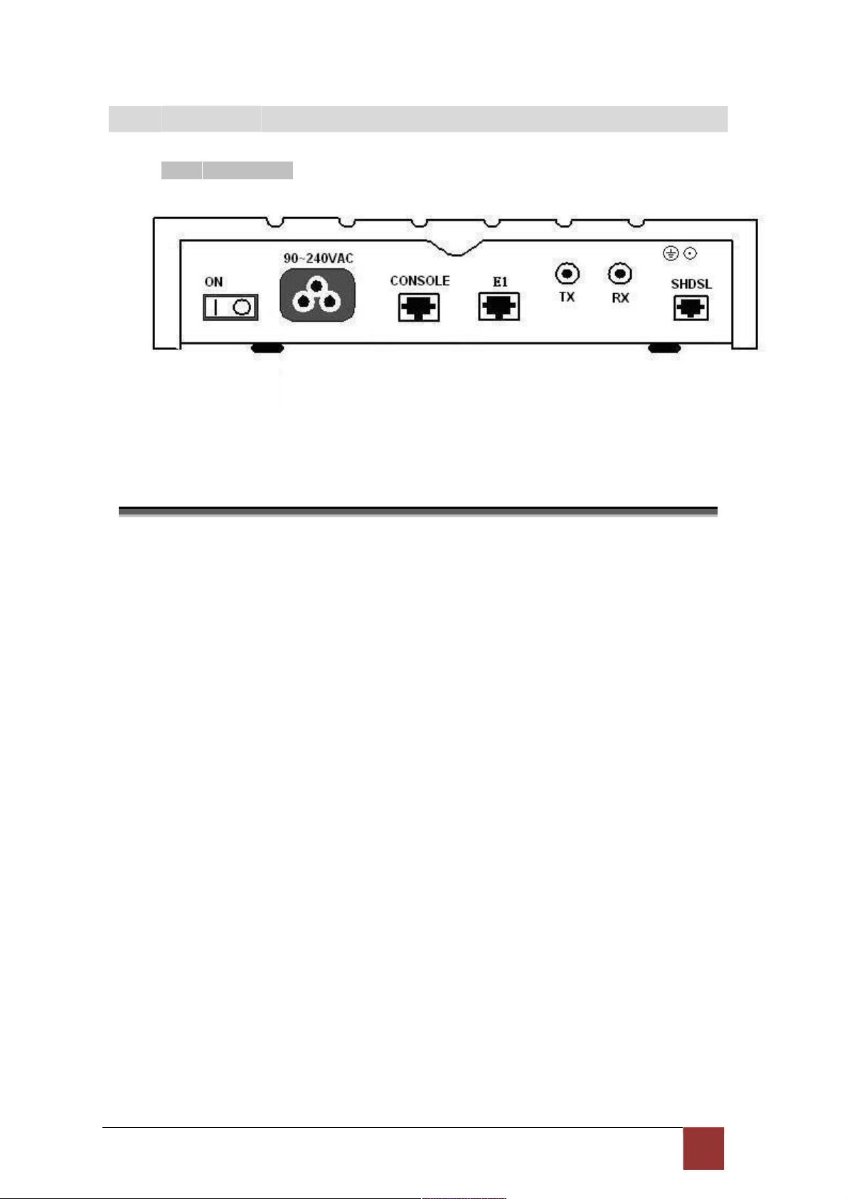
2.2.1. E1 Interface Model
The rear panel of this model is including power switch, power socket, RJ-45 console, RJ-45
G.703, BNC jack for transmitting and receiving and RJ-45 for SHDSL from left to right.
Connector
Description
ON Power switch. Press 1 for turn on and press 0 for off.
90~240V AC Power socket. It has power adapting function from 90V
to 240V. CONSOLE RJ-45 for system configuration and maintenance.
G.703
RJ-45 for 120Ω E1 connection with PABX (Private Automatic Branch
Exchange) or E1 Router
TX BNC for 75Ω E1 transmitting
RX BNC for 75Ω E1 receiving
SHDSL RJ-45 for DSL connection
10
Page 13
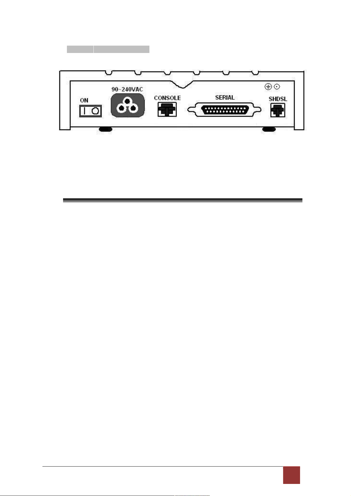
2.2.2. Serial (V.35) Interface Model
The rear panel of this model is including power switch, power socket, RJ-45 for console
cable, DB-25(Female) for V.35 cable and RJ-45 for SHDSL from left to right.
Connector
Description
ON Power switch. Press 1 for turn on and press 0 for off.
90~240V AC Power socket. It has power adapting function from
90V to 240V. CONSOLE RJ-45 for system configuration and maintenance.
SERIAL DB-25 for V.35 cable
SHDSL RJ-45 for DSL Connection
1 1
Page 14

2.2.3. Ethernet Interface Model
The rear panel of this model is including power switch, power socket, RJ-45 for console
cable, LAN for Ethernet cable and RJ-45 for SHDSL from left to right.
Connector Description
ON Power switch. Press 1 for turn on and press 0 for turn off.
90~240V AC Power socket. It has power adapting function from 90V to
240V. CONSOLE RJ-45 for system configuration and maintenance.
ETH RJ-45 LAN port for Ethernet cable
SHDSL RJ-45 for DSL Connection
12
Page 15

2.2.4. Three interface in one Model
The rear panel of this model is including power switch, power socket, RJ-45 for console cable,
LAN for Ethernet cable, RJ-45 G.703, BNC jack for transmitting and receiving, DB-25(Female)
for V.35 cable and RJ-45 for SHDSL from left to right.
Connector
Description
ON Power switch. Press 1 for turn on and press 0 for off.
90~240V AC Power socket. It has power adapting function from 90V
to 240V. CONSOLE RJ-45 for system configuration and maintenance.
ETH RJ-45 LAN port for Ethernet cable
E
1
RJ-45 for 120Ω E1 connection with PABX (Private Automatic Branch
Exchange) or E1 Router
SERIAL DB-25F for
V.35
cable
TX BNC for 75Ω E1 transmitting
RX BNC for 75Ω E1 receiving
DSL RJ-45 for DSL connection
1 3
Page 16

2
.3 In s t al lat io n
Note: To avoid possible damage to this NTU, do not turn on the product before
hardware installation.
(a) Plug the power cord in the power socket.
(b) Plug the console port in console if you want to configure the NTU with VT100 program of
NB or
PC.
(c) Plug the E1 cable (Either 75Ω BNC cables or 120Ω cable) / SERIAL cable / Ethernet
cable
(d) Plug SHDSL cable
(e) Power on
Model Interface modes support
E1 interface model E1 interface
V.35 interface model V.35 interface
Ethernet interface model Ethernet interface
Three interface in one model E1 interface
V.35 interface
Ethernet interface
E1+V.35 interface
E1+Ethernet interface
Only the three interfaces in one model can support all five type interface.
14
Page 17

2.3.1. E1 Interface
2.3.2. V35 Interface
1 5
Page 18

2.3.3. Ethernet Interface
Protective earth: The marked lug or terminal should be connected to the building
protective earth bus.
Before connecting this unit to a power source and connecting or disconnecting any other cable,
the protective earth terminals of this unit must be connected to the protective ground conductor
of the mains AC power cord. If you are using an extension cord (power cable) make sure it is
grounded as well. Any interruption of the protective (grounding) conductor (inside or outside the
instrument) or disconnecting of the protective earth terminal can make this unit dangerous.
Intentional interruption is prohibited.
!
Warning! High voltage. Do not open the housing
1 6
Page 19

3. Configuration with Keypad and LCD
This chapter provides information about configuration your G.XL-GDB102E via front
panel LCD display and keypads.
3
.1 K ey Pa d s
The product is designed for user-friendly configuration with keypads and LCD display
without using PC or NB with VT100 terminal.
Key Pad Description
Exit/- Return to previous configuration menu.
Enter/+ Skip to next configuration menu or configure the item.
L Select other parameter in the
same level menu. R Select other parameter in the
same level menu.
1 7
Page 20

3
.2 M ain m e nu Tr e e
After turning on device, the LCD display will prompt G.XL-GDB102E. Press Enter to enter.
There will display some sub-menu of the following.
Please notice that Ethernet interface mode haven’t SYSTEM
DIAGNOSTIC. For more detail on those sub-menu, please refer to each
chapter.
18
Page 21

3
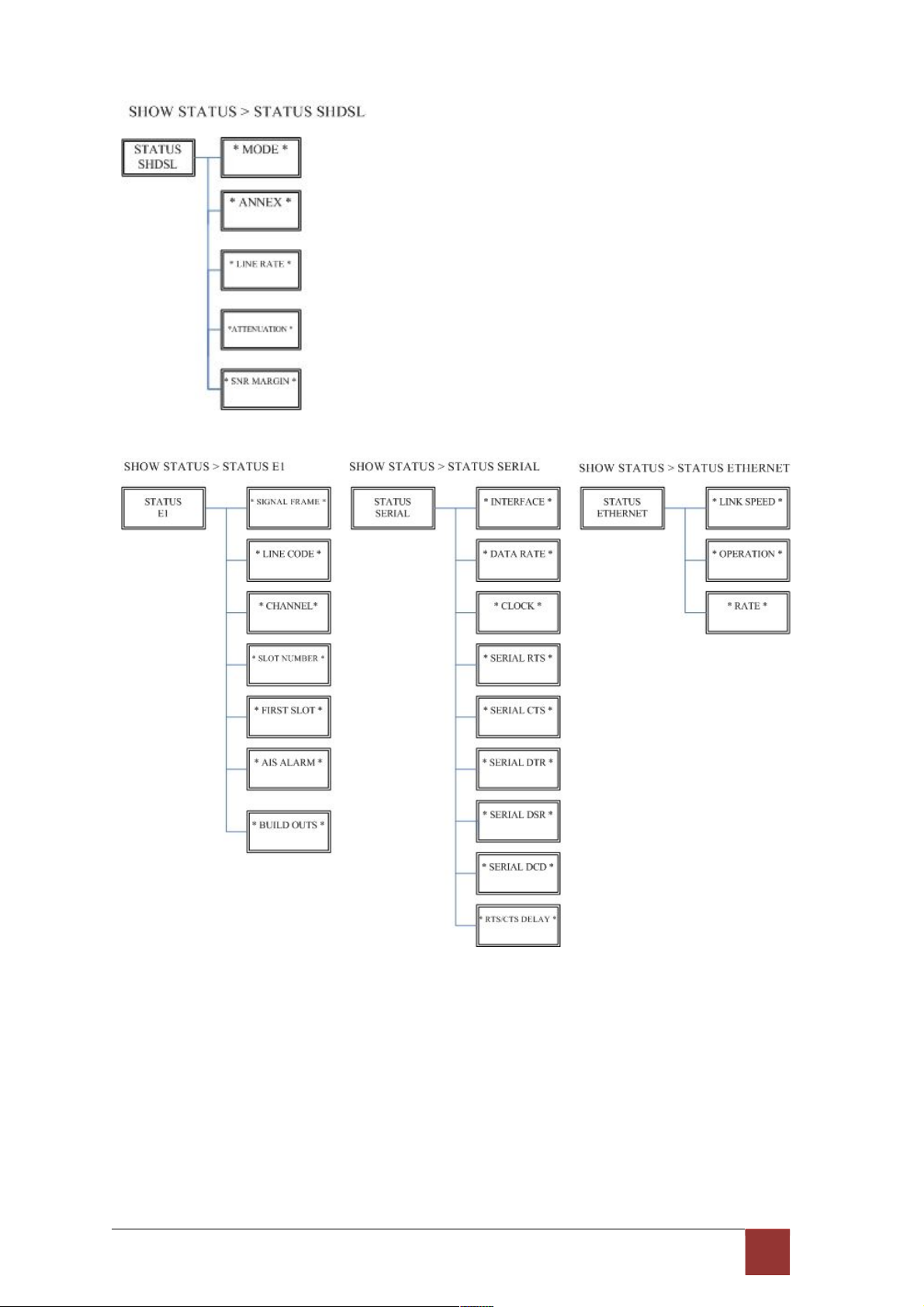
.3 M en u t ree for S H OW S TAT U S
You can check the status via LCD display.
The SHOW STATUS menu tree is as following.
19
Page 22
20
Page 23
3
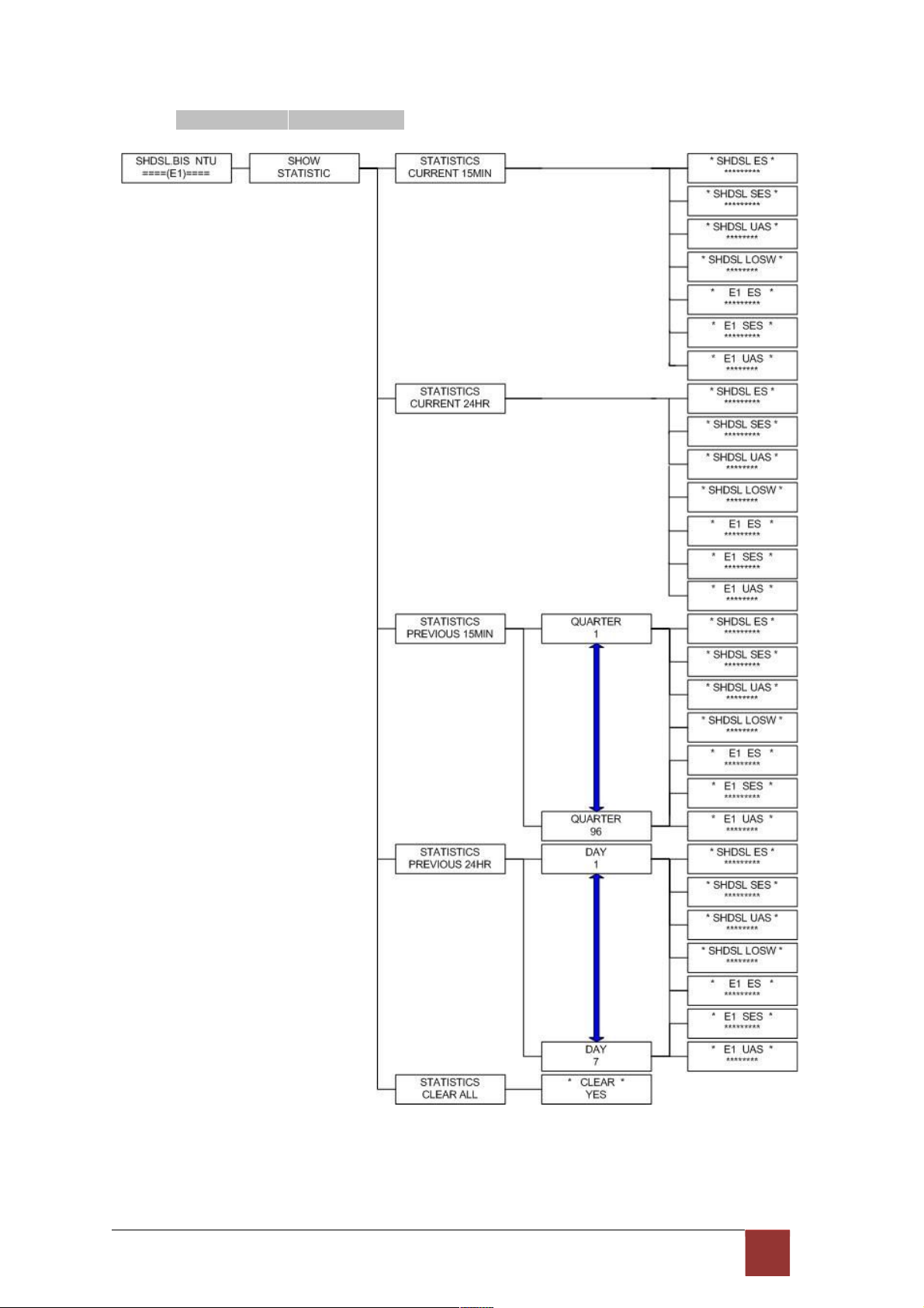
.4 M enu tr ee for S H OW S TAT IST IC S
The product can display two kinds of statistics data:
(a) Current 15 minutes period and 96 previous 15-minute period of SHDSL
performance. (b) Current 24 hour period and 7 previous 24-hour periods of SHDSL
performance.
If there using on E1 interface mode, it can also show the E1 performance data.
(c) Current 15 minutes period and 96 previous 15-minute period of E1
performance. (d) Current 24 hour period and 7 previous 24-hour periods of E1
performance.
SHDSL
ES
SES
UAS
LOSW
ES Error Second
SES Severely Error Second
UAS Unavailable Second
LOWS Loss of Synchronization word
E1
ES
SES
UAS
21
Page 24
3.4.1. Show Statistic on E1 Interface
22
Page 25
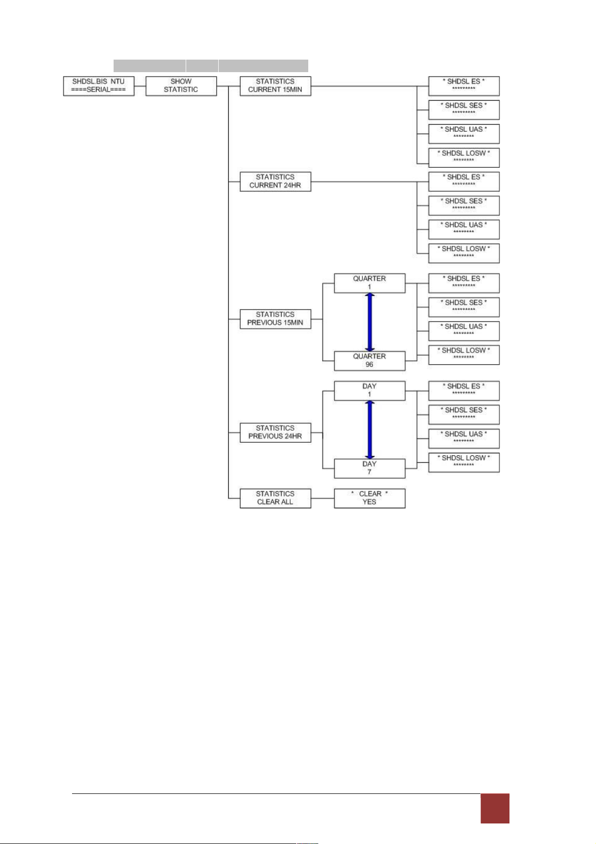
3.4.2. Show Statistic on Serial (V.35) Interface
23
Page 26

3.4.3. Show Statistic on Ethernet Interface
24
Page 27

3
.5 M enu tr ee for S YS T EM SE T UP
You can setup five interface mode via LCD display.
25
Page 28
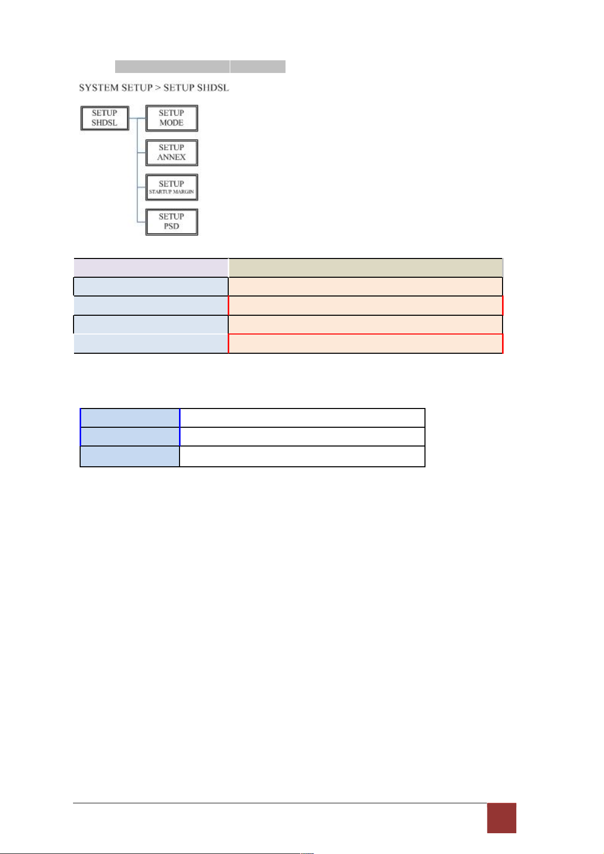
3.5.1. Sub-Menu tree for SETUP SHDSL
SETUP SHDSL Selection
items
SETUP MODE STU-R, STU-C-INTCLK, STU-C-EXTCLK
SETUP ANNEX A, B, F, G
SETUP STARTUP MARGIN -10 to 21
SETUP PSD SYM, ASYM
The following are commonly used acronyms for SETUP MODE:
STU-R
RT side, where the clock source is set to external
STU-C-INTCLK CO side, where the clock source is set to internal
STU-C-EXTCLK CO side, where the clock source is set to external
26
Page 29

3.5.2. Sub-Menu tree for SETUP E1 Interface
SYSTEM SETUP SETUP E1
E1 parameter setting:
E1 Items Setting
Channel PCM31
PCM31C
PCM30
PCM30C
FULL
Code HDB3
AMI
AIS On
Off
Build Outs 120 ohms
75 ohms
27
Page 30

Framer Setting:
Framer Slot Number First Slot
PCM31 FAS 1 to 31 1 to 31
PCM31C FAS+CRC4 1 to 31 1 to 31
PCM30 FAS+CAS 1 to 30 1 to 31 (can’t use 16)
PCM30C FAS+CAS+CRC4 1 to 30 1 to 31 (can’t use 16)
FULL UNFRAMED
28
Page 31

The first time slot setting:
Channel Number of slot
1
st
slot
FULL
(UNFRAMED)
----- -----
PCM31 PCM31C 31 1
30 1~2
29 1~3
28 1~4
27 1~5
26 1~6
25 1~7
24 1~8
23 1~9
22 1~10
21 1~11
20 1~12
19 1~13
18 1~14
17 1~15
16 1~16
15 1~17
14 1~18
13 1~19
12 1~20
11 1~21
10 1~22
9 1~23
8 1~24
7 1~25
6 1~26
5 1~27
4 1~28
3 1~29
2 1~30
1 1~31
PCM30 PCM30C 30 1
29 1~2
28 1~3
29
Page 32

27 1~4
26 1~5
25 1~6
24 1~7
23 1~8
22 1~9
21 1~10
20 1~11
19 1~12
18 1~13
17 1~14
16 1~15
15 1~15,17
14 1~15,17~18
13 1~15,17~19
12 1~15,17~20
11 1~15,17~21
10 1~15,17~22
9 1~15,17~23
8 1~15,17~24
7 1~15,17~25
6 1~15,17~26
5 1~15,17~27
4 1~15,17~28
3 1~15,17~29
2 1~15,17~30
1 1~15,17~31
30
Page 33
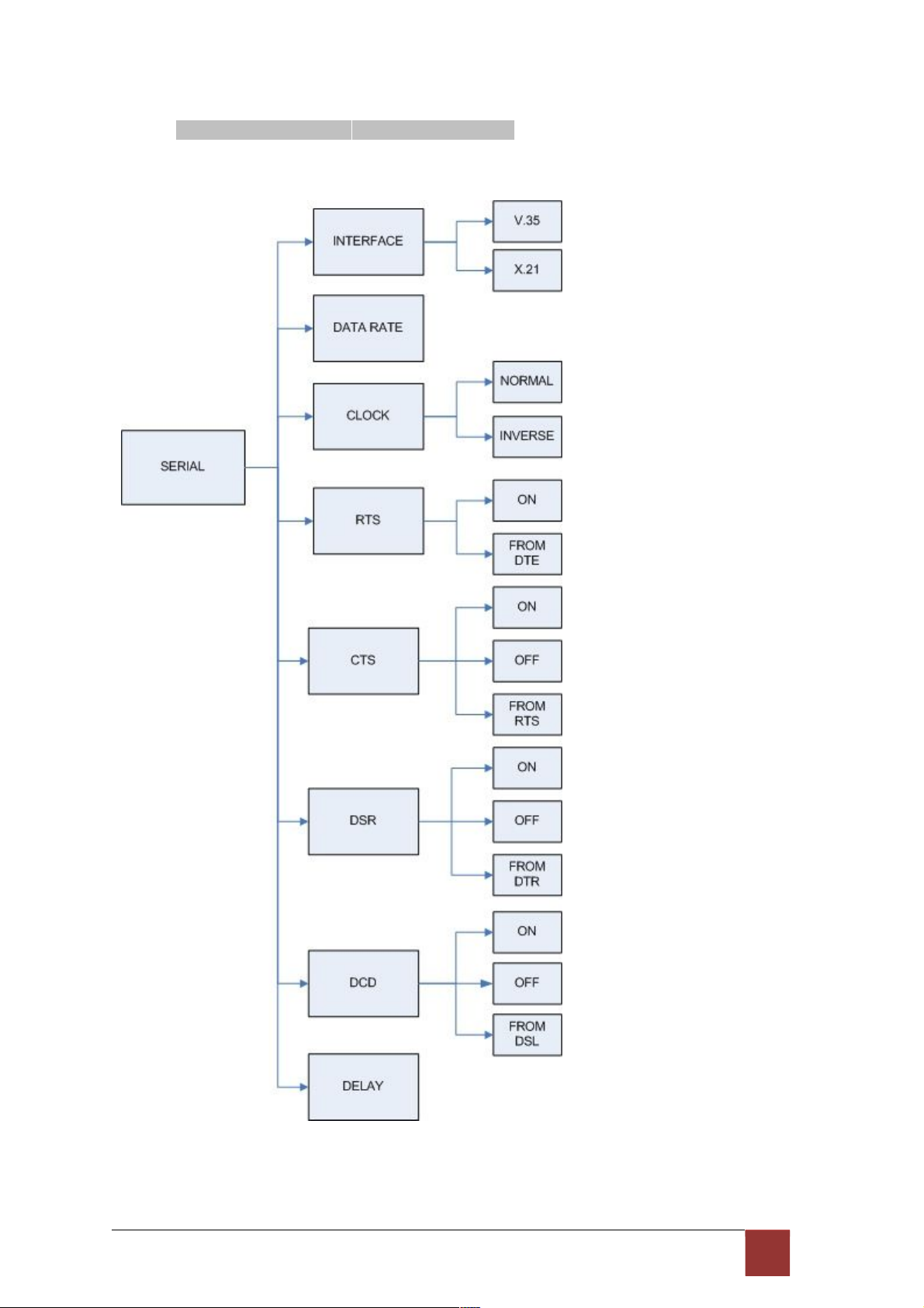
3.5.3. Sub-Menu tree for SETUP SERIES Interface
SYSTEM SETUP SETUP SERIES
3 1
Page 34

Serial interface control signal setting:
Serial Items Setting
INTERFACE V.35
X.21(RS-530)
Nx64K (Rate) 1 ~ 89 (Annex F/G)
1 ~ 36 (AnnexA/B)
CLOCK Normal
Inverse
RTS On
From DTE
CTS On
Off
From RTS
DSR On
Off
From DTR
DCD On
Off
From DSL
DELAY 0mS
1mS
2mS
3mS
32
Page 35

3.5.4. Sub-menu tree for SETUP Ethernet Interface
SYSTEM SETUP SET UP ETHERNET
If you set Ethernet Auto Negotiation is Enable, the default setting on Duplex is Full and Speed is
100M.
If you set Ethernet Auto Negotiation is as Enable, the Duplex and Speed can’t be set up
and using auto configuration.
Ethernet Items
Setting
Rate
1 ~ 89 (Annex F/G)
1 ~ 36 (Annex A/B)
Auto Disable Enable
Duplex Full-Duplex
Half-Duplex
Auto Configuration
Speed 100M
10M
Auto Configuration
33
Page 36
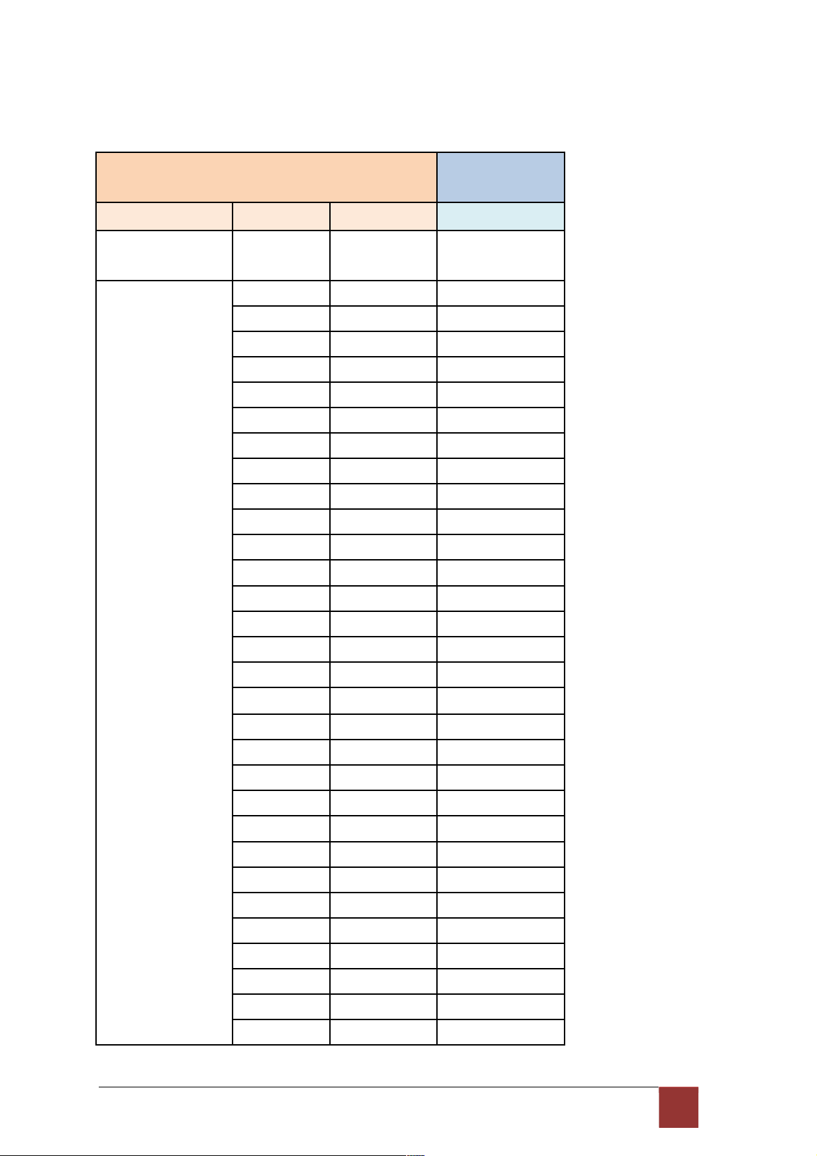
Table of E1+ Serial interface and E1+Ethernet interface mode (Annex A /B):
E1 interface Serial interface
Ethernet interface
Channel Number of slot
1
st
slot
Nx64K (Rate)
FULL
(UNFRAMED)
----- ----- 1~4
PCM31 PCM31C 31 1 1~5
30 1~2 1~6
29 1~3 1~7
28 1~4 1~8
27 1~5 1~9
26 1~6 1~10
25 1~7 1~11
24 1~8 1~12
23 1~9 1~13
22 1~10 1~14
21 1~11 1~15
20 1~12 1~16
19 1~13 1~17
18 1~14 1~18
17 1~15 1~19
16 1~16 1~20
15 1~17 1~21
14 1~18 1~22
13 1~19 1~23
12 1~20 1~24
11 1~21 1~25
10 1~22 1~26
9 1~23 1~27
8 1~24 1~28
7 1~25 1~29
6 1~26 1~30
5 1~27 1~31
4 1~28 1~32
3 1~29 1~33
2 1~30 1~34
34
Page 37

1 1~31 1~35
PCM30 PCM30C 30 1 1~6
29 1~2 1~7
28 1~3 1~8
27 1~4 1~9
26 1~5 1~10
25 1~6 1~11
24 1~7 1~12
23 1~8 1~13
22 1~9 1~14
21 1~10 1~15
20 1~11 1~16
19 1~12 1~17
18 1~13 1~18
17 1~14 1~19
16 1~15 1~20
15 1~15,17 1~21
14 1~15,17~18 1~22
13 1~15,17~19 1~23
12 1~15,17~20 1~24
11 1~15,17~21 1~25
10 1~15,17~22 1~26
9 1~15,17~23 1~27
8 1~15,17~24 1~28
7 1~15,17~25 1~29
6 1~15,17~26 1~30
5 1~15,17~27 1~31
4 1~15,17~28 1~32
3 1~15,17~29 1~33
2 1~15,17~30 1~34
1 1~15,17~31 1~35
35
Page 38

Table of E1+ Serial interface and E1+Ethernet interface mode (Annex F /G):
E1 interface Serial interface
Ethernet interface
Channel Number of slot
1
st
slot
Nx64K (Rate)
FULL
(UNFRAMED)
----- ----- 1~57
PCM31 PCM31C 31 1 1~58
30 1~2 1~59
29 1~3 1~60
28 1~4 1~61
27 1~5 1~62
26 1~6 1~63
25 1~7 1~64
24 1~8 1~65
23 1~9 1~66
22 1~10 1~67
21 1~11 1~68
20 1~12 1~69
19 1~13 1~70
18 1~14 1~71
17 1~15 1~72
16 1~16 1~73
15 1~17 1~74
14 1~18 1~75
13 1~19 1~76
12 1~20 1~77
11 1~21 1~78
10 1~22 1~79
9 1~23 1~80
8 1~24 1~81
7 1~25 1~82
6 1~26 1~83
5 1~27 1~84
4 1~28 1~85
3 1~29 1~86
2 1~30 1~87
36
Page 39

1 1~31 1~88
PCM30 PCM30C 30 1 1~59
29 1~2 1~60
28 1~3 1~61
27 1~4 1~62
26 1~5 1~63
25 1~6 1~64
24 1~7 1~65
23 1~8 1~66
22 1~9 1~67
21 1~10 1~68
20 1~11 1~69
19 1~12 1~70
18 1~13 1~71
17 1~14 1~72
16 1~15 1~73
15 1~15,17 1~74
14 1~15,17~18 1~75
13 1~15,17~19 1~76
12 1~15,17~20 1~77
11 1~15,17~21 1~78
10 1~15,17~22 1~79
9 1~15,17~23 1~80
8 1~15,17~24 1~81
7 1~15,17~25 1~82
6 1~15,17~26 1~83
5 1~15,17~27 1~84
4 1~15,17~28 1~85
3 1~15,17~29 1~86
2 1~15,17~30 1~87
1 1~15,17~31 1~88
37
Page 40
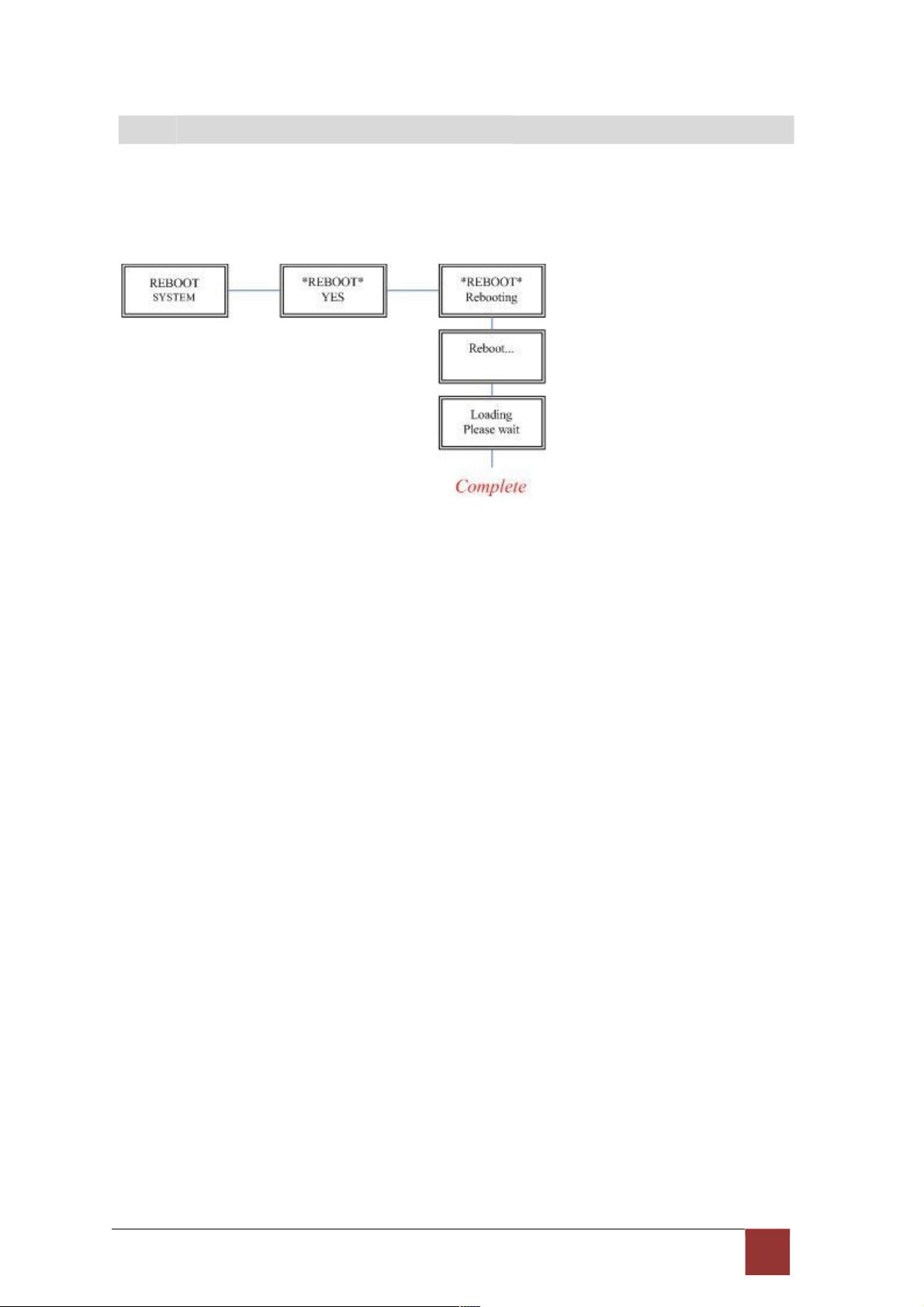
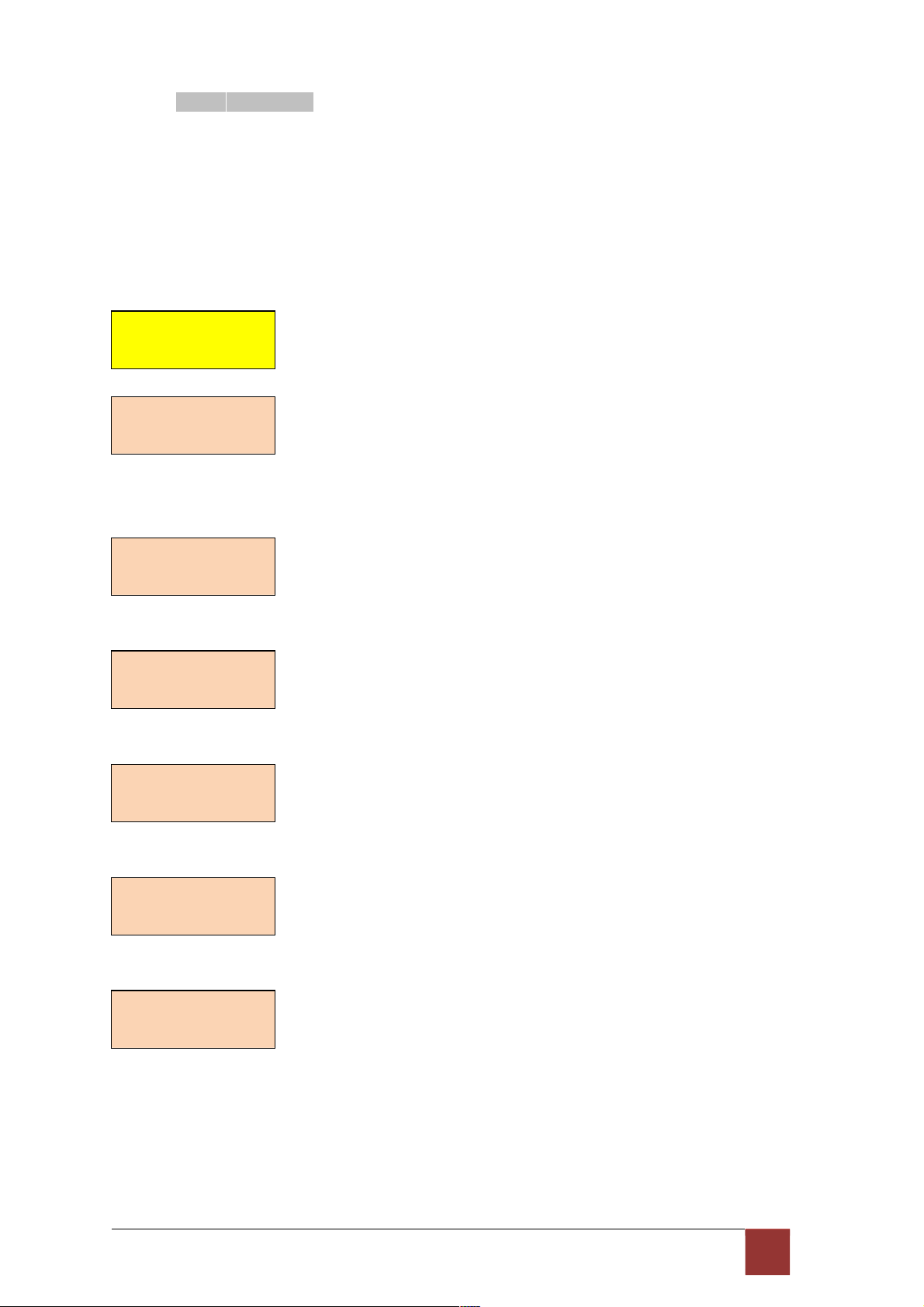
3
.6 S ub - me n u tree fo r RE B OOT S YST E M
REBOOT SYSTEM -> * REBOOT * YES -> press ”ENTER” key
Some setting must reboot the device after the “Save Configuration”, and then setting items
can take effect.
38
Page 41

3
.7 S ub - Me n u tree fo r DI S GN O ST IC
3.7.1. Loopback function
SYSTEM DIAGNOSTIC DIAG LOOPBACK
Note : No SYSTEM DIAGNOSTIC menu on Ethernet Interface Model
If the device haven’t connect or under handshake, there will not have farend line, farend
payload and V.54.
Stand alone NTU, no connection with other NTU:
E1 interface
CO side
Local digital
Local
Remote line
Remote payload
E1 interface
CPE side
Local digital
Remote line
Remote payload
After connection both CO side and CPE side:
E1 interface
CO side
Local digital
Local
Remote line
Remote payload
Farend line
Farend payload
E1 interface
CPE side
Local digital
Remote line
Remote payload
Farend line
Farend payload
Serial interface
CO side
Local digital
Local
Remote line
Remote payload
Serial interface
CPE side
Local digital
Remote line
Remote payload
Serial interface
CO side
Local digital
Local
Remote line
Remote payload
Farend line
Farend payload
V.54
Serial interface
CPE side
Local digital
Remote line
Remote payload
Farend line
Farend payload
V.54
39
Page 42

404142
Page 43

Page 44
3.7.2. BER Test function
SYSTEM DIAGNOSTIC DIAG BER TEST
This is the internal Bit Error Rate Tester (BERT) for complete testing of local and remote
modem and the link quality without any external test equipment.
This built-in Bit Error Rate Test generator can generates a standard 2047 (2
1
1
-1) test pattern.
DIAG
BER
TEST
*BERT
2047*
RUN
When the BERT haven’t any Bit Error, it show zero. Otherwise, it will show some number
counter. RUN(SEC) item is show the time elapsed second count
RUN(SEC): 00001
BIT ERR: 00000
If there have NO SYNC on bit error message, it shows the testing paths haven’t
connected. RUN(SEC): 00001
BIT ERR: NO SYNC
Press ENTER key on this display message, it will re-sync again.
*BERT 2047*
RESYNC
Press ENTER key on this display message, it will show the test real time.
*BERT 2047*
INFO
If you want to exit the BERT, please press ENTER key from this display message.
*BERT 2047*
DISABLE
Page 45
4. Configuration with Console Port
This chapter will deal with the specifics of configuration and operation of this product via
console port with terminal emulation program. The configuration G.XL-GDB102E is performed
via a menu-driven embedded software, using a standard ASCII terminal or a PC running a
terminal emulation application connected to the rear panel CONSOLE port.
Windows includes a terminal emulation program called HyperTerminal. Connect the appropriate
communication port from the PC to this device. After the physical connection is made, you are
ready to configure this product. Make sure you have connected the supplied RS-232C serial
cable (DB9F to RJ-45 Plug) to the console port on the rear panel on this product.
Run the terminal emulation program such as Hyper Terminal with the following
setting: Emulation: VT-100 compatible
Band rate: 115200 , Data bits: 8, Parity: None , Stop Bits:1 , Flow Control: None
4
.1 L og in P ro c ed u re
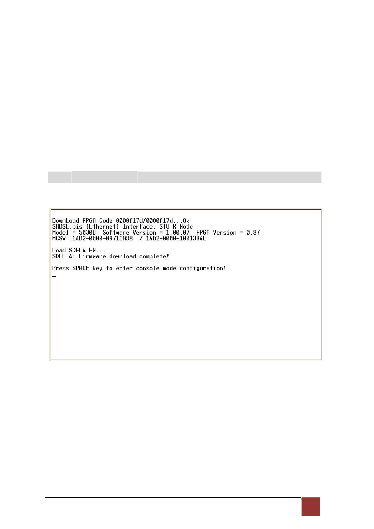
At the start up screen, you will see:
43
Page 46

Press the SPACE key until the login screen appears. When you see the login screen, you
can logon to device. Username use “admin”. When the system prompts you for a password,
type
“admin” to enter is O.K.
4
.2 Win d ow st r uc tur e
After you type the password, there will displays the main menu.
44
Page 47
Above screen capture shows the common structure for all windows used throughout the
configuration console terminal.
From top to bottom, the window is divided into four major
sections.
The very top line displays the product name.
Next a block of commands is listed where the ">>" symbol indicates the current cursor
placeholder.
The next block down is the "command" section. The command that is selected and ready for
execution is displayed after the "Command:" prompt. The "<more…> designation indicates
that there are other sub menus to this command. The "Message:" field is used to display any
special system messages or warnings.
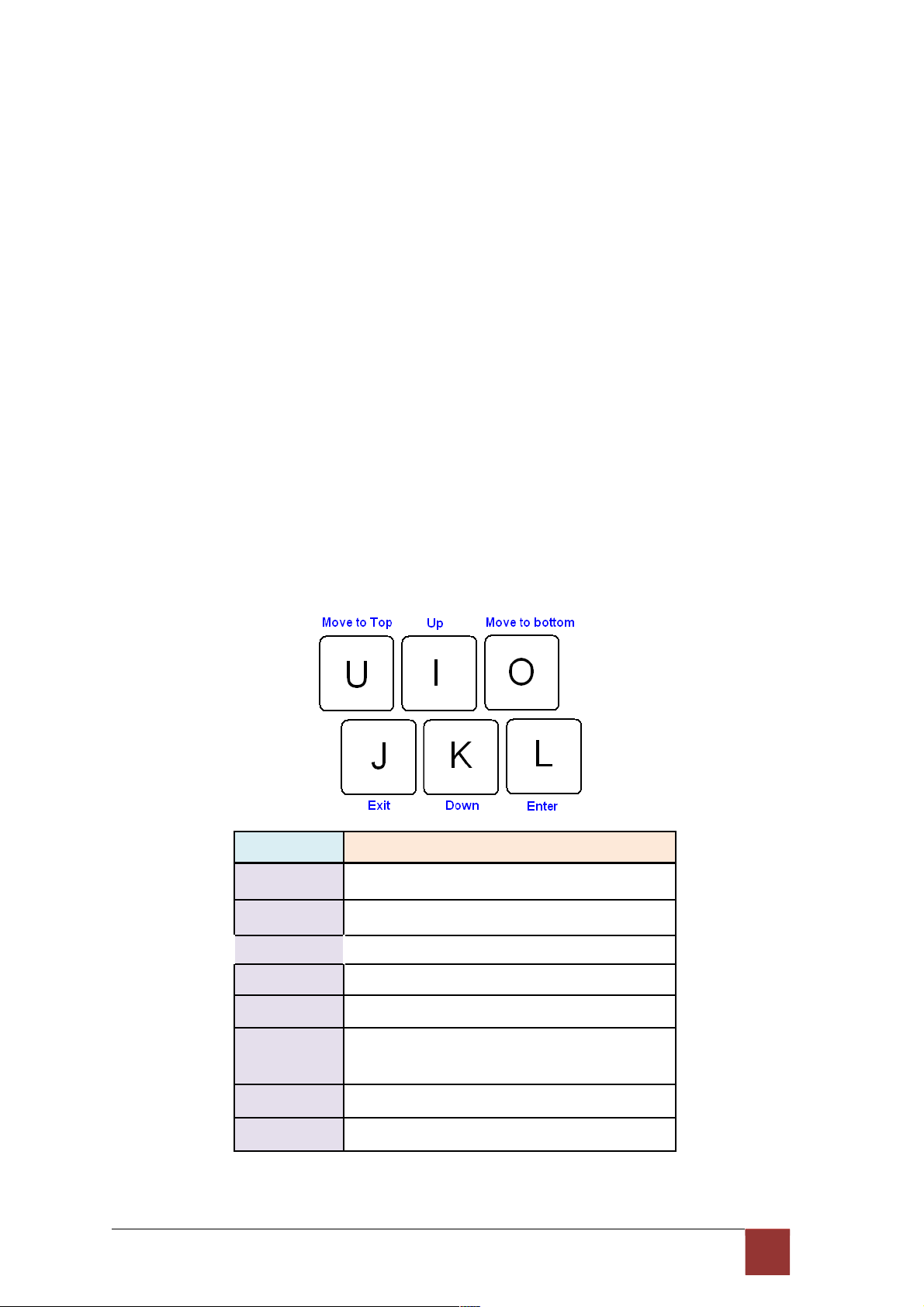
Finally, at the very bottom of the screen is a help command line and reminder of the currently
available command keys. In most cases, the keyboards four cursor keys can be used to
navigate all the menu system. If for some reason your keyboard's cursor keys are not
supported in the terminal emulation software, you may uses the keys listed on the help
command line.
Menu Commands
Before changing the configuration, familiarize yourself with the operations list in the following
table. The operation list will be shown on the window.
Keypads Description
[UP] or I
Move to above field in the same level menu
[DOWN] or K
Move to below field in the same lever menu
U
Move to top field in the same level menu
O
Move to bottom field in the same level menu
[LEFT] or J
Move back to previous menu (Exit)
[RIGHT] or L
[ENTER]
Move forward to submenu(Enter)
[TAB] To choose another parameters
Ctrl + C To quit the show data display screen
45
Page 48

4
.3 M ain Me nu Su m ma r y
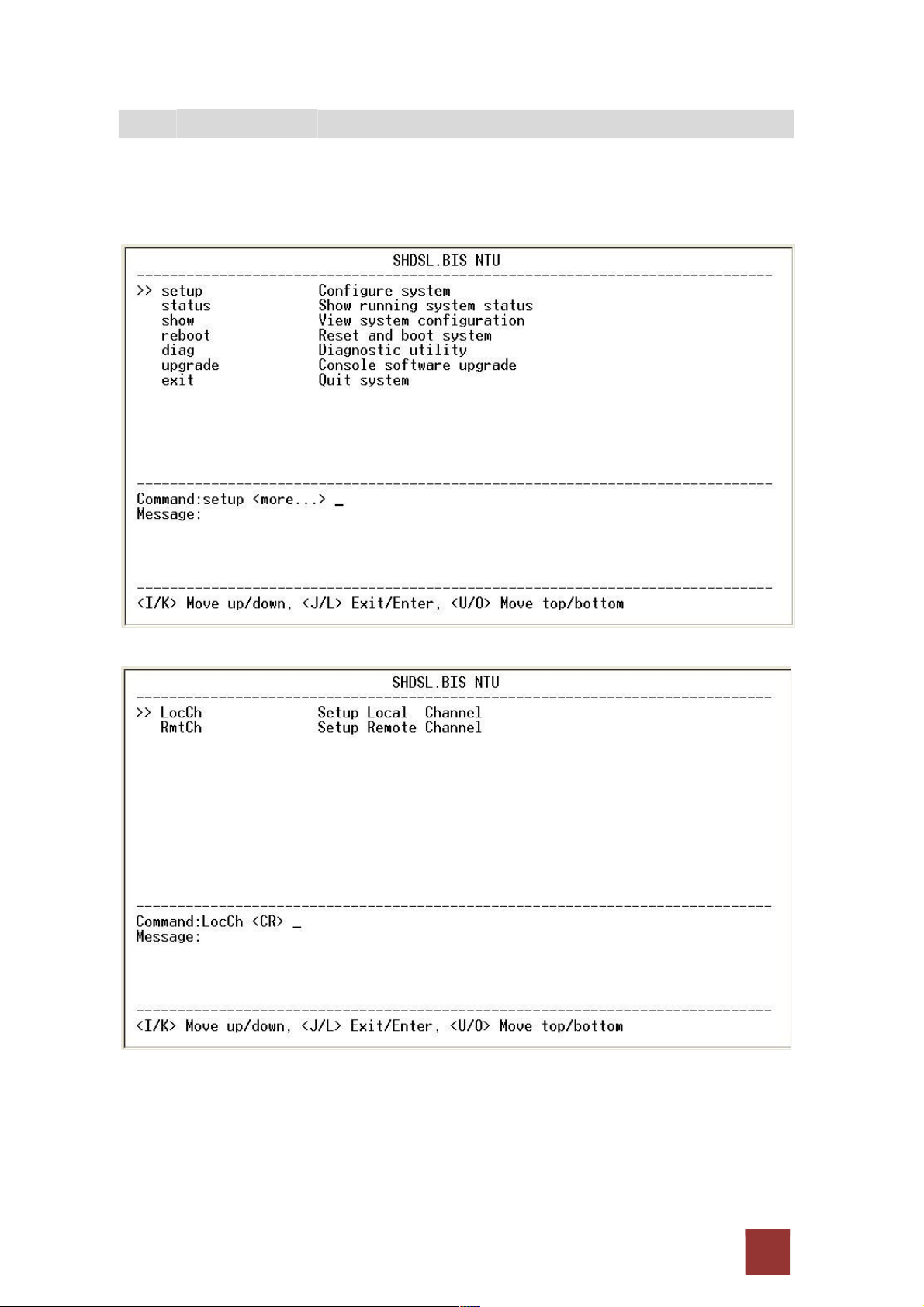
The main menu is prompt as follow.
Menu Title
Function
Setup
Use this menu to setup SHDSL type, SHDSL parameters and E1
parameters or restore factory default setting.
Status Use this menu to show SHDSL status, E1 /V.35/Ethernet status and
statistics or clear the statistics
Show
Use this menu to show general information, all configurations and all
configurations in command script.
Reboot Use this menu to reset and reboot the system
Diag
Use this menu to setup diagnostic utility
Upgrade Use this menu to upgrade kernel and FPGA.
Exit
Use this menu to exit
No diagnostic function on main menu for two case:
(1) Use Ethernet interface model.
(2) Use Three interface in one model, but working as Ethernet interface only.
46
Page 49
4
.4 C on fig u ra t ion
This section provides information about configuration the XL-GDB102E. Follow the
procedures:
In main menu, select setup and press [ENTER] or [RIGHT]
The screen will prompt as following
If you setup the local side, select LocCH and press [ENTER] or [RIGHT].
Otherwise, setup the remote side by select RmtCH.
47
Page 50

4.4.1. Configure NTU Interface
If the XL-GDB102E is the three interfaces in one model, it will display five types of
interface can select.
48
Page 51

Model Interface modes support
E1 interface model E1
Serial interface model Serial
Ethernet interface model Ethernet
Three interface in one model E1
Serial
Ethernet
E1+Serial
E1+Ethernet
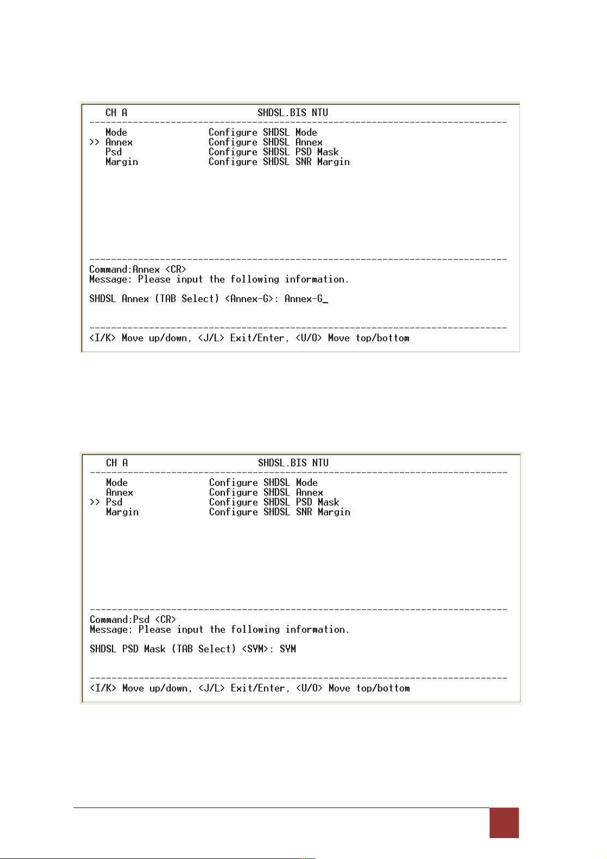
4.4.2. Configure SHDSL parameters
This section provide to setup SHDSL parameters: SHDSL Mode, Annex type, Psd Mask, SNR
margin.
Select Shdsl, and press [ENTER] or [RIGHT].
Press [TAB] to select the operating type and press enter to finish setting.
The SHDSL modes have three types: STU-R, STU-C-INTCLK, STU-C-EXTCLK
INTCLK: The device will generate the appropriate clock speed defined by the speed setting of
the interface.
EXTCLK: The device will accept the clock from the interface and will use that clock to receive
and transmit data across the interface.
Most applications use Internal Clock. If the DTE provides a clock with TX data, the clock can set
to be External Clock.
49
Page 52
For setting the
SHDSL
Annex type, move the cursor to Annex and press [ENTER]. Select
the annex type by using [TAB] key.
The Annex have four mode: A, B, F and G.
For configuring SHDSL PSD, move the cursor to psd and press [ENTER]. Select the
parameter via [TAB] key.
The PSD have two types: SYM and ASYM.
50
Page 53

For setting SHDSL Margin, move the cursor to margin and press [ENTER]. Select the margin via
[TAB] key and key in the Next margin.
SNR margin is an index of line connection. You can see the actual SNR margin in STATUS
SHDSL. The larger SNR margin has the better line connection. For example, if you set SNR
margin in the field as 3, the SHDSL connection will drop down and reconnect when the SNR
margin is lower
than 3.
The setting range is -10 to 21.
5 1
Page 54
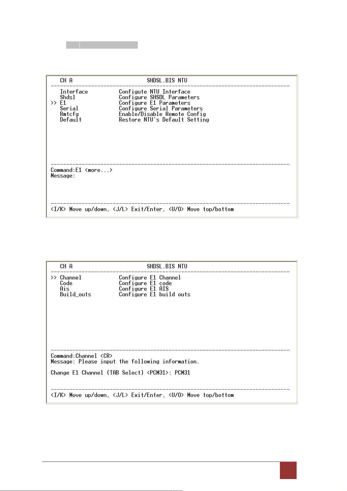
4.4.3. Configure E1 parameters
When using on E1 interface, select the E1 item and press [ENTER] or [RIGHT].
The E1 settings include the Channel (frame mode), line code, AIS and build out settings.
Setup E1 Parameter, Channel
52
Page 55

Framing is required to recover the channelized E1. In transparent operation, the framing is
configured as Unframed. In this case the G.SHDSL framer must be set to Nx64 with N=32. For
any framing such as FAS or CAS, the G.SHDSL framer must be set to E1, then the E1 framing
here may be set accordingly.
PCM31 FAS
PCM31C FAS+CRC4
PCM30 FAS+CAS
PCM30C FAS+CAS+CRC4
FULL Unframed
FAS Frame Alignment Signal use 7-bit pattern to establish and maintain
frame synchronization. The FAS word is located in timeslot 0 of
frame. In FAS mode there are 1~31 timeslot available for use data.
CAS Also known as time slot 16 multiframing. It requires a multiframe
alignment signal to be present for frame sync. The Multiframe
Alignment Signal (MFAS) is inserted into the 16th timeslot of frame 0
of the 16-frame multiframe.
In CAS mode, there are 30 channels available for user data. If timeslot
16 is included in the unit’s mapping, it will be disregarded.
Time Slot
0 1 2 3
4
64k 64k 64k 64k
64k
5 ~ 15
704k
16
64k
17 ~ 30
896k
31
64k
Data Rate (x) 960kbps
Data Rate (y) 960kbps
Maximun Data Rate = x + y = 1920kbps
CRC4 The CRC-4 checksum bits are transmitted in the outgoing E1
data stream. Also the received signal is checked for errors.
CRC-4 checksum cannot be sent in unframed mode.
Unframed In this mode, user data is inserted into all 32
channels (64k x 32
=
2048k) of the E1 stream. The object of running without framing is
to utilize the full bandwidth of the E1 line.
FAS CAS
53
Page 56
Time Slot
0 1 2 3 4 5 6 7
8
9 ~ 30
31
64k 64k 64k 64k 64k 64k 64k 64k 64k 1408k 64k
Maximun Data Rate 2048kbps
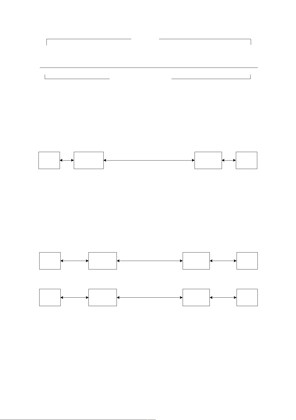
ITU 991.2 (2004) (G.SHDSL .Bis) supports data rate up to 56964Kbps, but G.703 (E1) only
supports data rate of 2048kbps so the maximum data rate of SHDSL line, connected with
E1
DCEs, depends on data rate of E1, 2048kbps. There are two types of frames on SHDSL line, E1
and N x 64k. E1 frame only use for connection with E1 DCEs.
E
1 SHDSL
E1
DTE
STU-C (E1)
STU-R (E1)
DTE
Frame E1
Data rate 2048
If the connection is E1 vs V.35 or V.35 vs E1, the frame has to be used N x 64k. In this case,
the data rate depends on value of N. Same as above case, SHDSL and V35 can support
2304kbps
data rate (36 x 64k) but E1 supports maximum data rate of 2048kbps (32 x 64k).
E1
SHDSL
S
TU-R
V.
35
DTE
STU-C (E1)
Frame N x 64 (N=1~32)
(
V.35)
DTE
V.
35 SHDSL
E1
DTE
STU-C (V.35)
STU-R (E1)
DTE
Frame N x 64 (N=1~32)
Time slot, N value, is place of data in the frame. Time Slot Number 1~31 (N=1~31) is Fractional
E1 and Time Slot Number 32 (N=32) is unframed.
Fractional E1
Page 57

For fractional E1, FE1, the data rate is from 64k, N=1, to 1984k, N=31, according to the E1
frame. If the E1 frame is FAS or FAS+CRC4, there are 1~31 available time slot for use data. If
the data rate of SHDSL line set to be 512k, the time slot number is 8 and first time slot number is
1. The frame is shown as below.
Page 58

Time Slot
0 1 2 3 4 5 6 7
8
9 ~ 30
31
64k 64k 64k 64k 64k 64k 64k 64k 64k 1408k 64k
The First Time Slot setting of FAS and FAS+ CRC4 have to follow the rule:
RUL
E
F
irst Time Slot
≦ 31- Time Slot Numbe
r
Using E1 frame of FAS+CAS or FAS+CAS+CRC4, the FAS will occupy Time Slot 0 and CAS Time
Slot 16. There are only 30 Time Slot left for data. On the other hand, the data rate is 1920kbps.
Time Slot
0 1 2 3
4
64k 64k 64k 64k
64k
5 ~ 15
704k
16
64k
17 ~ 30
896k
31
64k
The First Time Slot setting of FAS+CAS and FAS+CAS+CRC4 have to follow the rule:
RUL
E
F
irst Time Slot
≦ 30 - Time Slot Numbe
r
Unframed E1
Time Slot
0 1 2 3 4 5 6 7
8
9 ~ 30
31
FAS Data Data Data Data Data Data Data Data
FAS CAS
Page 59

Data Data Data Data Data Data Data Data Data Data Data
64k 64k 64k 64k 64k 64k 64k 64k
64k
1408k 64k
Page 60
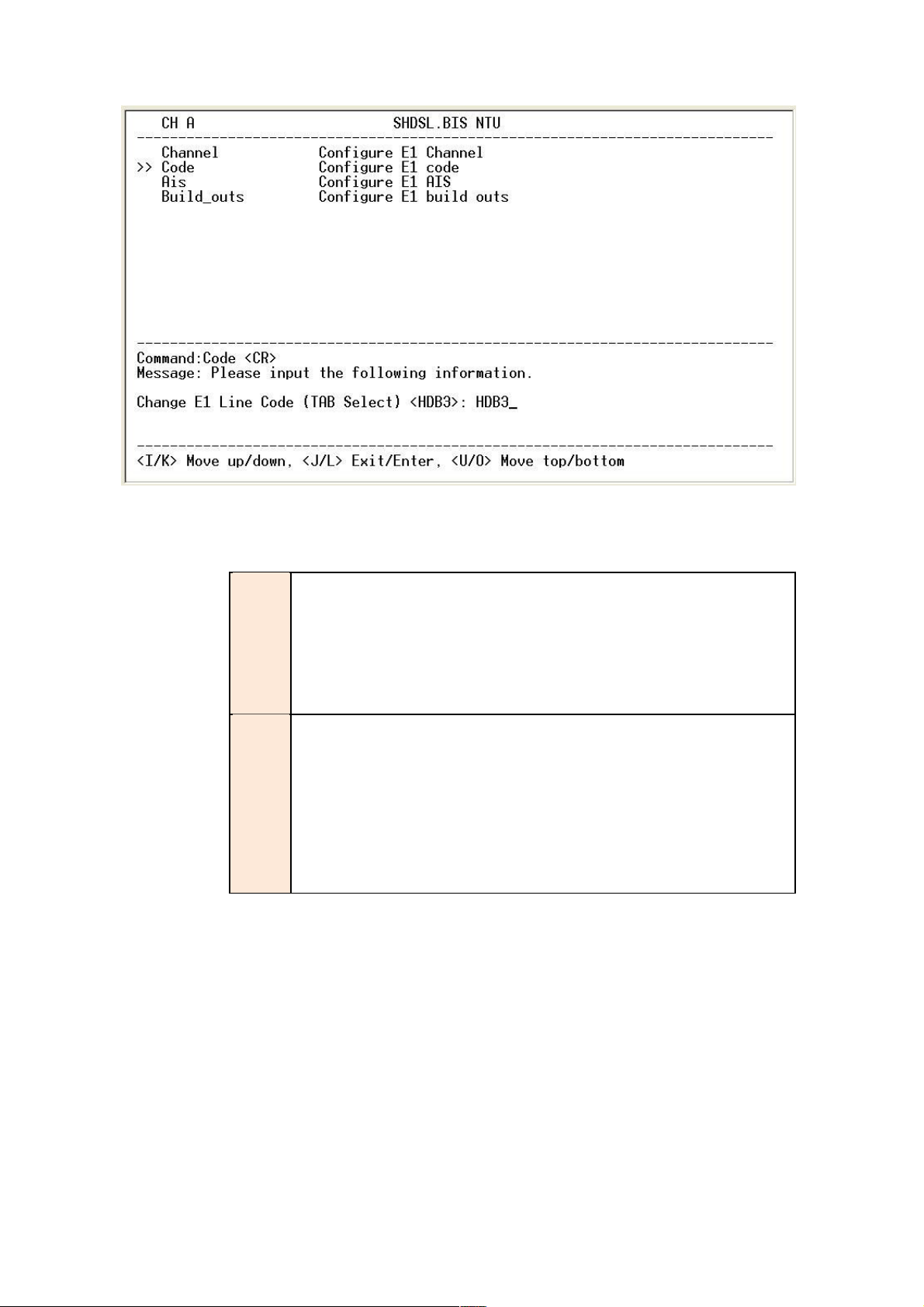
Setup E1 Parameter, Line Code
The G.XL-GDB102E supports two different line codings. HDB3 is the most popular and
preferred line coding and is also the default setting. AMI line coding is also selectable.
`
HDB3
In this line coding, the transmitter substitutes a deliberate bipolar
violation when excessive zeros in the data stream are detected. The
receiver recognizes these special violations and decodes them
as
zeros.
This method enables the network to minimum pulse density
requirements. Unless AMI is required for your application, HDB3 should
be used whenever possible.
AMI
Alternate Mark Inversion defines a pulses as a “mark,” a binary one as,
as opposed to a zero. In an E1 network connection, signals are
transmitted as a sequence of one and zero. One is sent as pulse, and
zero is sent as spaces, i.e. no pulse. Every other pulse is inverted from
the previous pulse in polarity, so that the signal can be effectively
transmitted. This means, however, that a long sequence of zero in data
stream will cause problems, since the NTU receiving the signal relies on
the signal to recover the 2048kbps clock.
Page 61
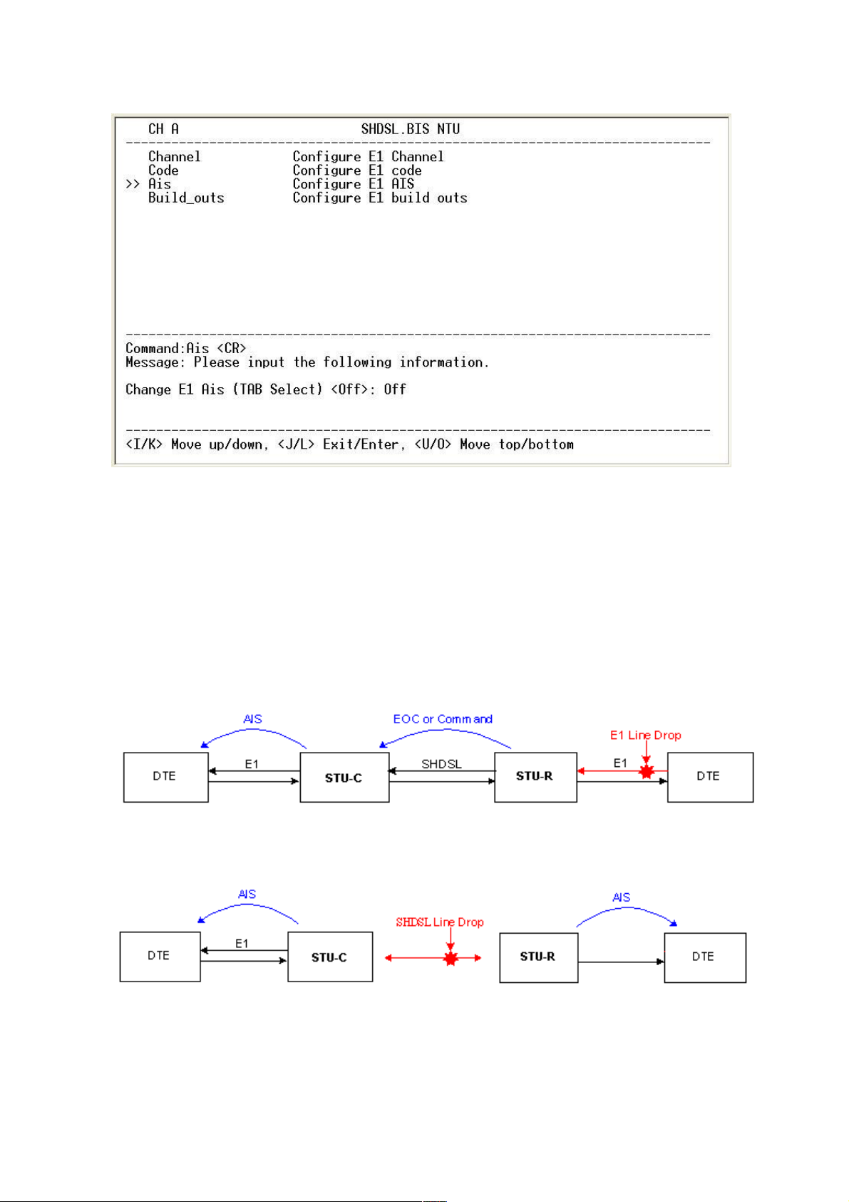
Setup E1 Parameter, AIS
AIS (Alarm Indication Signal) is a method to inform the remote connection that there is a signal or
sync problem with the E1. AIS is only valid in framed mode E1, not in Unframed E1. The setting
here of AIS enabled (on) or not (off) and is for testing with AIS. When enabled, the E1 will
transmit the AIS and it should be confirmed at the remote device (AIS indication lit). After testing,
please turn AIS back off.
For example 1: When STU-R E1 RX line is drop, STU-R sends the status to STU-C via
EOC or command, and then STU-C will send AIS (Alarm Indication Signal) to DTE while
AIS function is enabled.
For example 2: When SHDSL connection drops, STU-R and STU-C both send AIS (Alarm
Indication Signal) to DTE in the same time while AIS function is enabled.
Page 62

Setup E1 Parameter, Build Out
The XL-GDB102E can support both unbalanced E1 at 75 ohms and balanced E1 at 120 ohms.
The settings for impedance are made here under the build out menu setting.
Page 63

4.4.4. Configure Serial parameters
When using on Serial interface, select the Serial item and press [ENTER] or
[RIGHT]. The serial settings include the data rate, clocking and handshaking lines
setup.
Setup Serial Parameter, Interface
There have two interfaces: V.35 and RS-530(X.21) can be setup.
Setup Serial Parameter, Data Rate
Page 64

For Annex A and B, the rate can be adjusted in increments of 64kbps from 64kbps to 2304kbps
(N=1~36).
For Annex F and G, the rate can be adjusted in increments of 64kbps from 64kbps to 5696kbps
(N=1~89).
Setup Serial Parameter, Clock Polarity
The data port clock polarity may be adjusted to solve some rare clocking issues. The default
setting is 'Normal' clock polarity, where data is sent on the positive transition of the clock, while
the option exists to set inverse clock polarity where data is sent on the negative clock transition.
Setup Serial Parameter, RTS
60
Page 65

The behavior of the RTS (Request To Send) signal may be set in one of two ways. When set
'on', the RTS signal is always forced high (on, positive voltage or SPACE), when set 'from DTE'
the RTS signal will follow the DTE's condition. The default setting for RTS is on.
Setup Serial Parameter, CTS
The behavior of the CTS (Clear To Send) signal may be set in one of three ways. When set
'on', the CTS signal is always forced high (on, positive voltage or SPACE), when set 'off' the
signal is always forced low (off, negative voltage or MARK), or CTS will follow RTS (Request
To Send) condition of 'on' for RTS on 'off' for RTS off. The default setting for CTS is to follow
RTS.
6 1
Page 66

Setup Serial Parameter, DSR
The behavior of the DSR (Data Set Ready) signal may be set in one of three ways. When set
'on', the DSR signal is always forced high (on, positive voltage or SPACE), when set 'off' the
signal is always forced low (off, negative voltage or MARK), or DSR will follow DTR (Data
Terminal Ready) condition of 'on' for DTR on or 'off' for DTR off. The default setting for DSR is
on.
Setup Serial Parameter, DCD
The behavior of the DCD (Data Carrier Detect) signal may be set in one of three ways. When set
'on', the DCD signal is always forced high (on, positive voltage or SPACE), when set 'off' the
signal is always forced low (off, negative voltage or MARK), or DCD will follow the DSL condition
of 'on' for DSL link or 'off' for no link. The default setting for DCD is to follow the DSL link status.
62
Page 67

Setup Serial Parameter, Delay
The delay setting is used to cause a delay for CTS to follow RTS. The delay setting may be
set from 0 to 3 milliseconds. The default setting is 3 milliseconds.
4.4.5. Configure Ethernet parameter
When using on Ethernet interface mode, select the Ethernet item and press [ENTER] or [RIGHT].
The Ethernet settings include the data rate, negotiation, duplex the speed.
63
Page 68
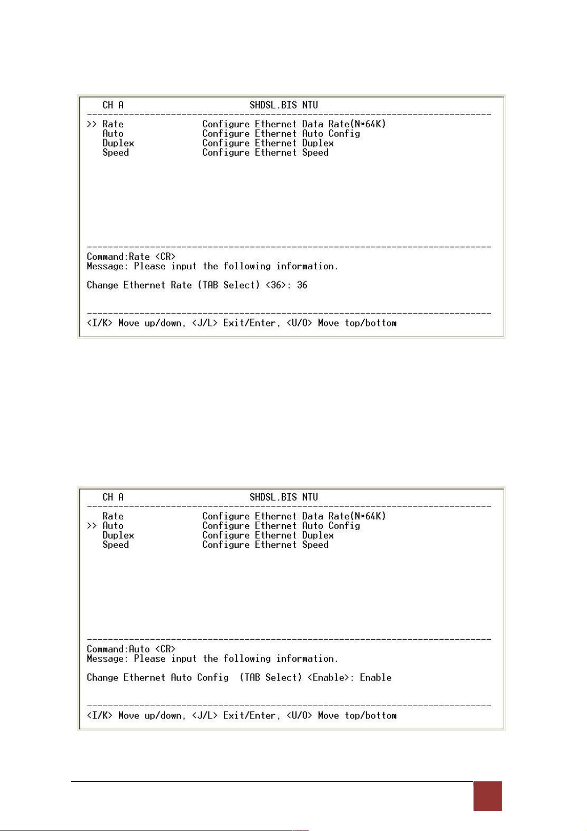
Setup Interface Parameter, Data Rate
For Annex A and B, the rate can be adjusted in increments of 64kbps from 64bps to 2304kbps
(N=1~36).
For Annex F and G, the rate can be adjusted in increments of 64kbps from 64bps to 5696kbps
(N=1~89).
Setup Interface Parameter, negotiation
You can select Enable and Disable on auto negotiation function.
64
Page 69
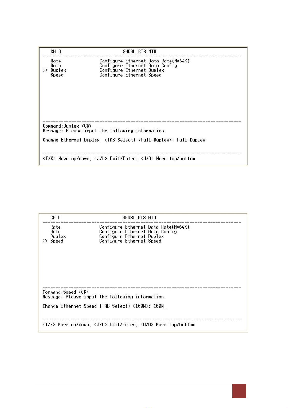
Setup Interface Parameter, Duplex
When auto negotiation setup to disable, there have select on duplex mode: Full-Duplex and
Half-Duplex.
Setup Interface Parameter, Speed
When auto negotiation setup to disable, there have select on speed setting: 10M and 100M.
If auto negotiation setup to Enable, the items Duplex and Speed can’t been set. The message
will display “Ethernet is in auto negotiate”.
65
Page 70

4.4.6. Remote configuration
You can set the “Enable/Disable function” to let the side remote side can configure parameters
to this device remotely.
4.4.7. Restore factory default
The G.XL-GDB102E can have all settings restored to their original factory settings simply by
going to the setting menu, selecting the Default item, and then press ENTER. The system will
ask for a y(es) or n(o) confirmation followed by an ENTER.
66
Page 71
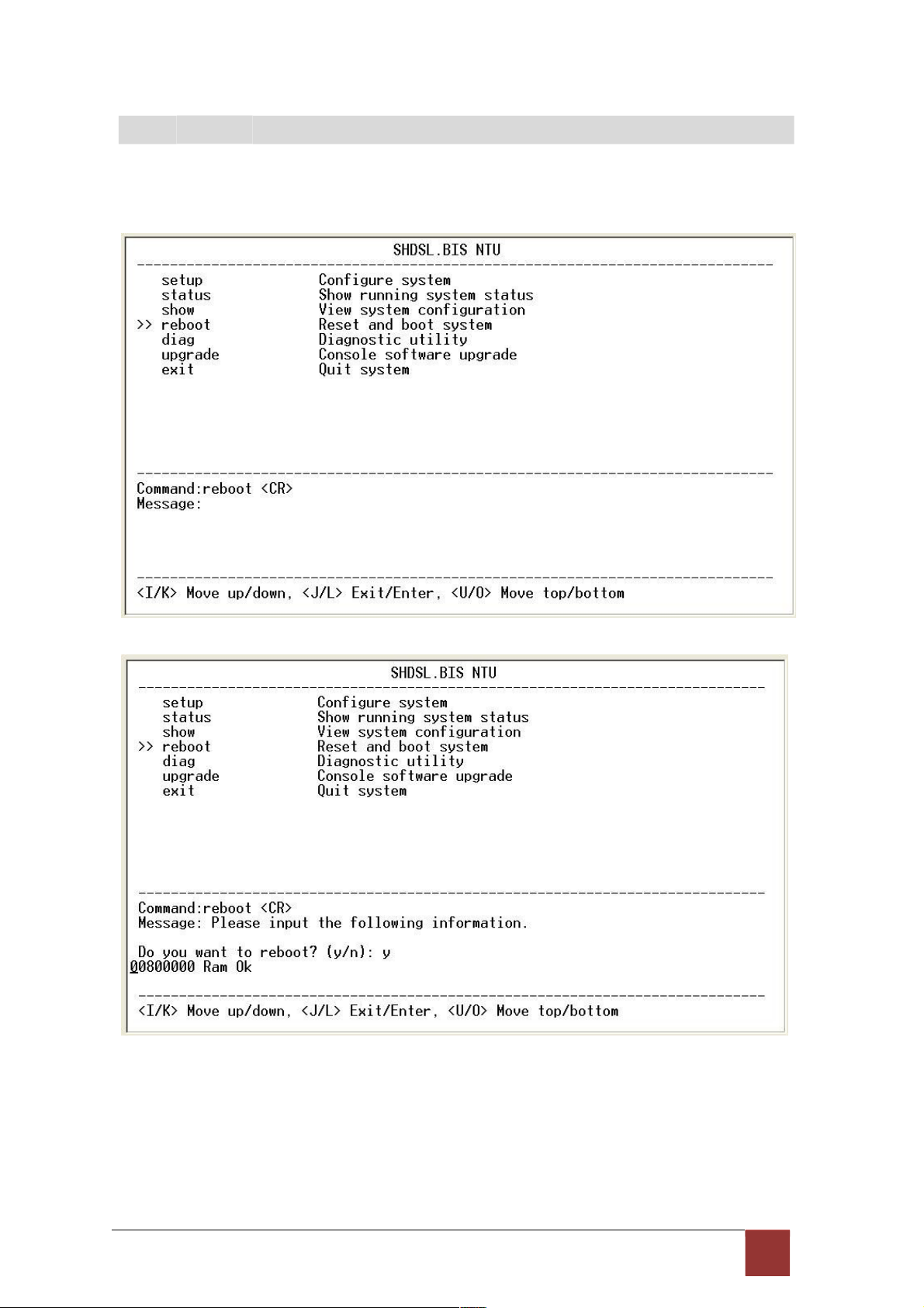
4
.5 R eb o ot
In main menu, move the cursor to reboot and press [ENTER]. The device will reboot
after confirming.
After the reboot operation have finished, RAM test are starting again.
67
Page 72
4
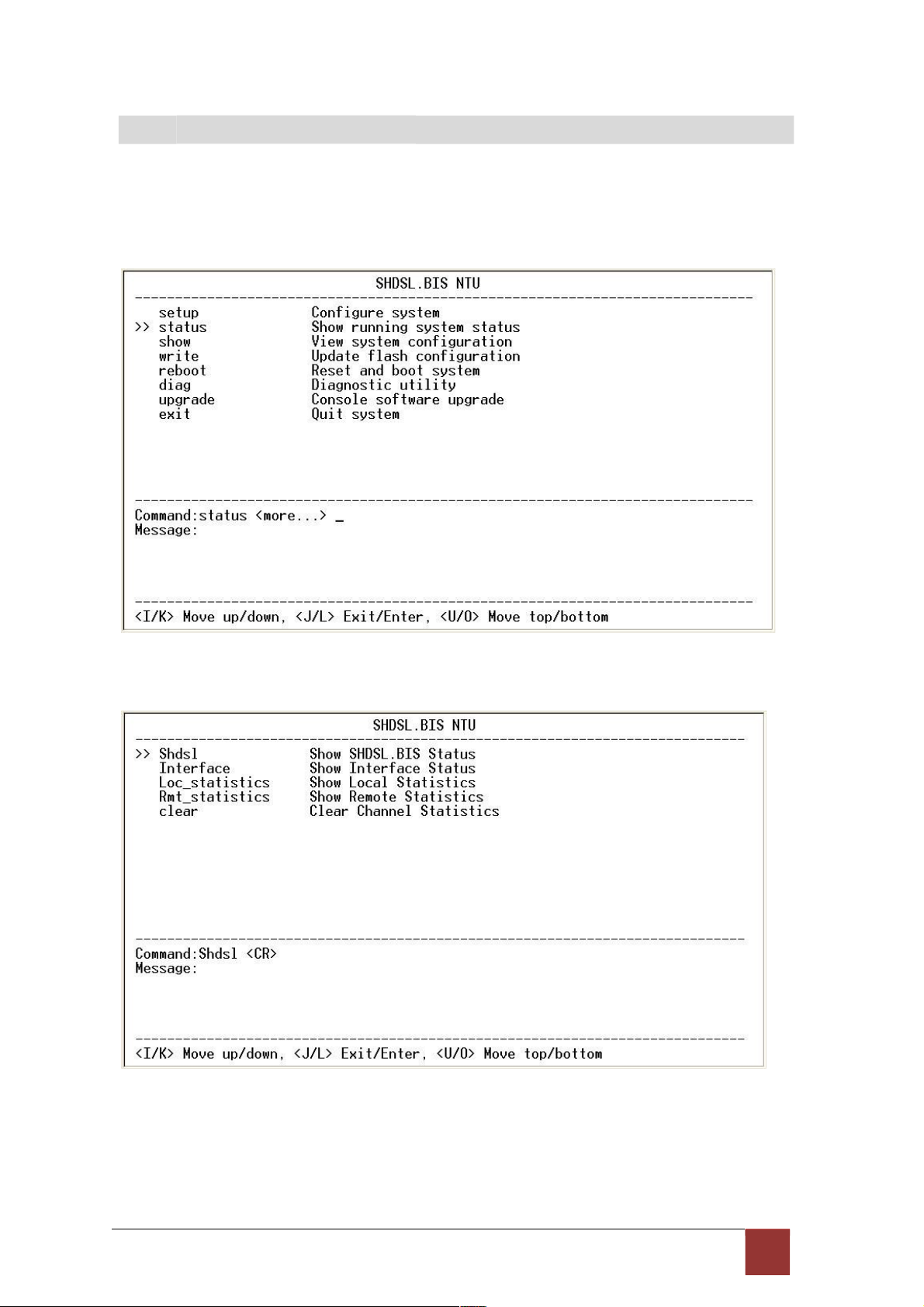
.6 V iew th e s ys t e m s t at u s
You can use the status command to view the status of SHDSL, E1, Serial and Interface as
well as statistic and clear the statistic log. Select status and press [ENTER].
Select SHDSL command to show the status of SHDSL.
68
Page 73

The SHDSL status will display a real-time status of the DSL on local side and remote side if
connected. The screen is refreshed about every 1.5 seconds. The monitoring window displays
the DSL line parameters, such as SNR margin and attenuation. The lower half of the window
displays the loopback and BER test status. While in this display mode the terminal window will
not timeout. To exit the window, press CTRL-C to quit.
69
Page 74

4
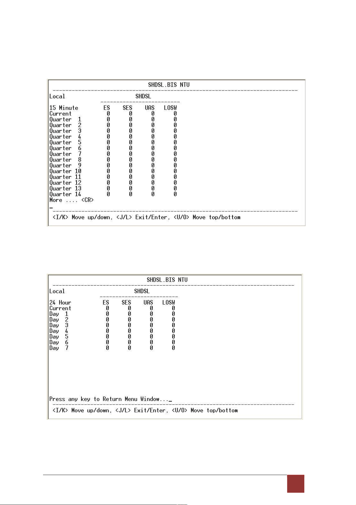
.7 V iew th e S ta tis t ic
Select Loc_statistic command to show the statistic information in 15 minutes or 24 hour via [TAB]
to choose.
The statistics display window will display performance monitor data for the selected interval (15
minutes or 24 hours). The display will show the recorded results for ES (error seconds), SES
(severely errored seconds), UAS (unavailable seconds), and LOSW (loss of sync word). W hile in
this display mode the terminal window will not timeout. The 15 minute display window will display
all the performance information for each 15 minute interval in the current 24 hour period. There
are a total of 96 intervals. Press the ENTER key to display the next page of intervals. To exit the
window, press CTRL-C and then ENTER.
The performance monitor is capable of storing and retrieving performance information for each
24 hours interval, up to 7 days.
70
Page 75

For E1 Interface model, there have SHDSL and E1 item.
View the performance monitor data for the selected interval 15 minutes:
View the performance monitor data for the selected interval 7days:
7 1
Page 76
For Serial and Ethernet Interface model, there have only SHDSL item.
View the performance monitor data for the selected interval 15
minutes:
View the performance monitor data for the selected interval 7 days:
72
Page 77

To clear the statistic log file, select clear and press [ENTER].
If you want to show the remote side’s statistics, please use the Rmt-statistics function as
the following.
73
Page 78

The following are commonly used acronyms:
ES Number of errored seconds in which one or more CRC (Cyclic Redundancy Check) error
events occurred during the current interval. This value is updated every time.
UAS Number of unavailable seconds in which a failed signal occurred during the current
interval. This value is updated every time.
SES Number of severely errored seconds in which 832 or more CRC error events occurred
during the current interval. This value is updated every time.
LOSW Number of seconds with loss of sync word during the current interval. This value is
updated every time.
74
Page 79

4
.8 V iew S yst e m C on fig ur a ti o n
By using show command, you can view the system configuring. Select show and press [ENTER]
or [RIGHT].
To show system information, please select system and press [ENTER] or [RIGHT]. The
screen will prompt the system information.
75
Page 80
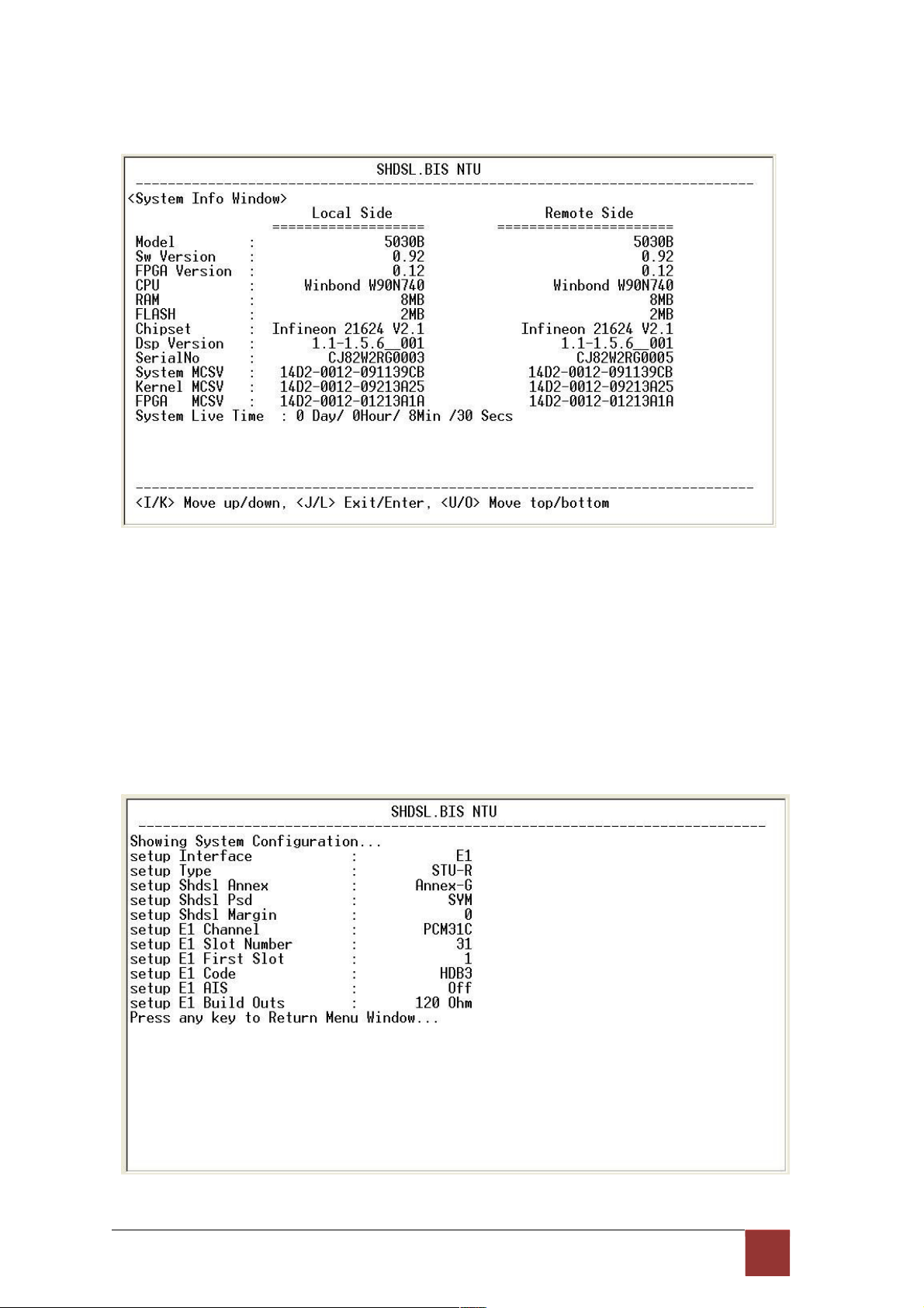
Our cursor is already on the System command, so press ENTER and the following screen
will display the general system information.
Most of the information on this screen is either self explanatory or it is simply irrelevant for the
end user. However, two items, the Kernel (SW Version)and FPGA (Field Programmable Gate
Array) version will give the software and hardware versions respectively of NTU. These are
important to know in case new firmware becomes available in the future to add extra functions of
to
fix unknown
bugs from the original manufactured equipment.
To show the system configuration, please select Config and press [ENTER] or [RIGHT].
The screen will prompt the all configuration data.
For E1 interface mode:
76
Page 81

For Serial interface mode:
For Ethernet interface mode:
77
Page 82

For E1 and Serial interface mode:
For E1 and Ethernet interface mode:
78
Page 83
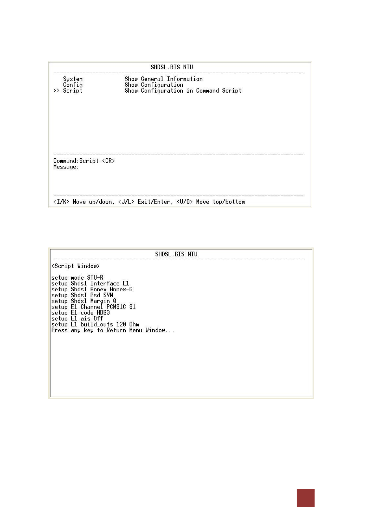
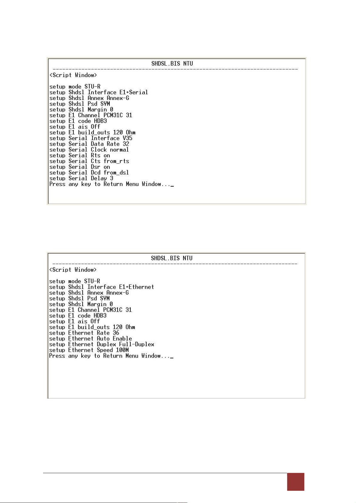
To show the system script file, please select Script and press [ENTER] or [RIGHT]. The
screen will prompt the configuration in script type.
For E1 interface mode:
79
Page 84
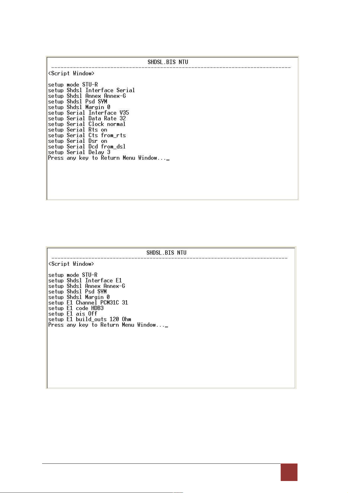
For Serial interface mode:
For Ethernet interface mode:
80
Page 85
For E1 and Serial interface mode:
For E1 and Ethernet interface mode:
81
Page 86
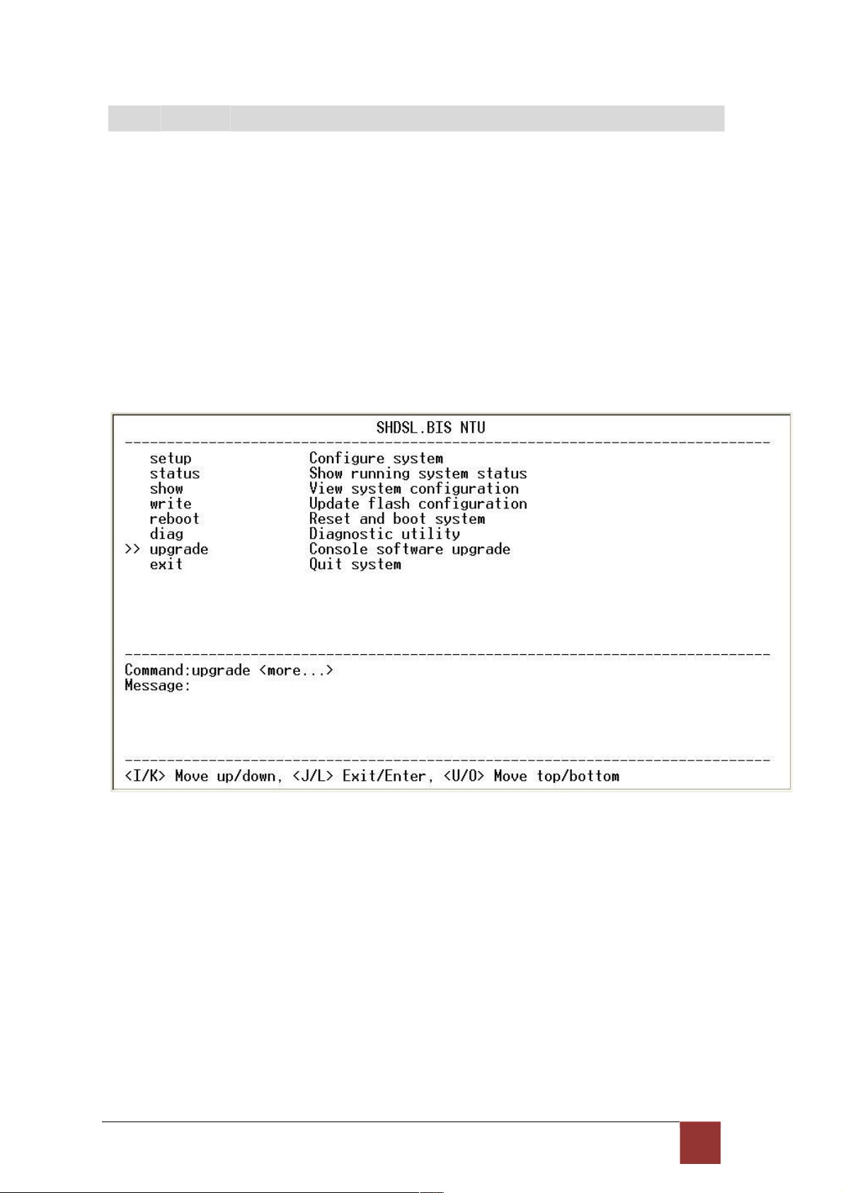
4
.9 U pg r ad e
This section will introduce how to upgrade the kernel and FPGA code of G.XL-GDB102E.
Select upgrade in main menu and press [ENTER] or [RIGHT].
Please notice that when you use Remote Upgrade feature. It means you can use those feature to
update firmware to remote side. It will describe below.
During on upgrade and re-flash, the normal transmissions will be halted, so the upgrade should
be done when the system is taken offline or done during a time of extremely low impact to the
customer’s line.
The upgrade process use the Xmodem protocol via the rear panel’s serial console
port. Following show the upgrade feature :
Before upgrading the NTU, you must have the main software or FPGA code in your
computer. If you want to upgrade the kernel:
Select Kernel and press [ENTER] or [RIGHT].
82
Page 87

Click Send file in terminal access program, hyper terminal, to send the file. Make sure the
sending protocol is Xmodem. Select the source file in window and press OK.
Once the upgrade is complete, there required to male the final confirmation to erase and re-write
the flash with new code.
When it was upgrading, you can see as following:
If you want to upgrade the FPGA code: Select FPGA and press [ENTER] or [RIGHT].
83
Page 88

When it was upgrading, you can see as following:
84
Page 89

This is the remote upgrade feature:
Before upgrading the NTU, you must have the Kernel code and FPGA code in your computer.
WARNING!!: Do not allow any interruption of power during the erase and re-write operation
or the Flash will be left in an unknown state and the device will no longer be able to function.
The device must then be returned to the factory for repair.
85
Page 90

4
.10 Di a gn o st ic
The diagnostic facility allows you to test the different aspects of your G.XL-GDB102E to
determine if it is working properly. Select diag and press [ENTER] or [RIGHT].
Loopback can test whether the NTU is properly worked with the connection
device. Press [ENTER] or [RIGNT] to setup the loopback.
For E1 Interface model as CO side, there have: Local Digital, local, remote line, remote
payload, farend line and farend payload.
For Serial Interface model as CO side, there have: Local Digital, local, remote line, remote
payload, farend line, farend payload and V.54.
86
Page 91
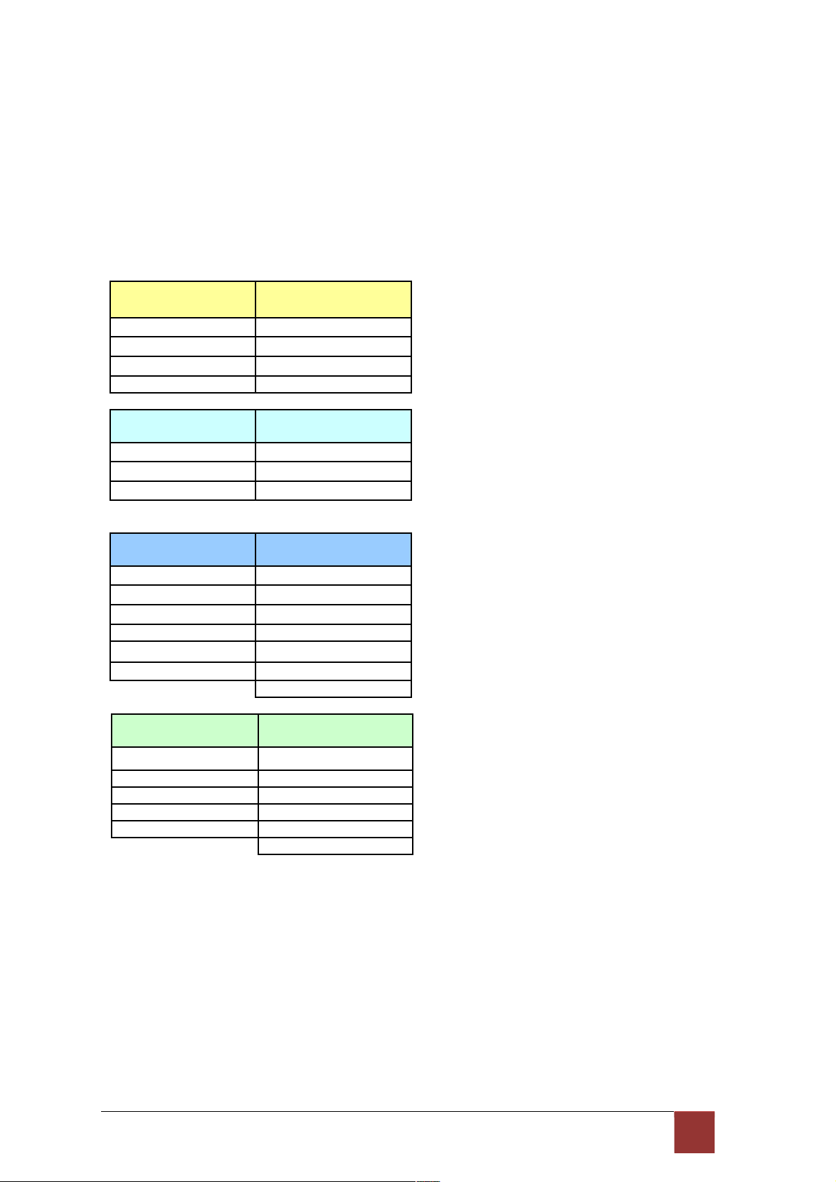
For E1 Interface model as CPE side, there have: Local Digital, remote line, remote payload,
farend line and farend payload.
For Serial Interface model as CPE side, there have: Local Digital, remote line, remote
payload, farend line, farend payload and V.54.
If the device haven’t connect or under handshake, there will not have farend line, farend
payload and V.54.There are no diagnostic function on Ethernet interface model.
Stand alone NTU, no connection with other NTU:
E1 interface
CO side
Serial interface
CO side
Local Digital Local Digital
Local Local
Remote line Remote line
Remote payload Remote payload
E1 interface
CPE side
Serial interface
CPE side
Local Digital Local Digital
Remote line Remote line
Remote payload Remote payload
After connection both CO side and CPE side:
E1 interface
CO side
Serial interface
CO side
Local Digital Local Digital
Local Local
Remote line Remote line
Remote payload Remote payload
Farend line Farend line
Farend payload Farend payload
V.54
E1 interface
CPE side
Serial interface
CPE side
Local Digital Local Digital
Remote line Remote line
Remote payload Remote payload
Farend line Farend line
Farend payload Farend payload
V.54
Definition of V.54
An ITU standard (1976) for various loopback tests that can be incorporated into modems
for testing the telephone circuit and isolating transmission problems.
Operating modes include local and remote digital loopback and local and remote analog loopback.
87
Page 92
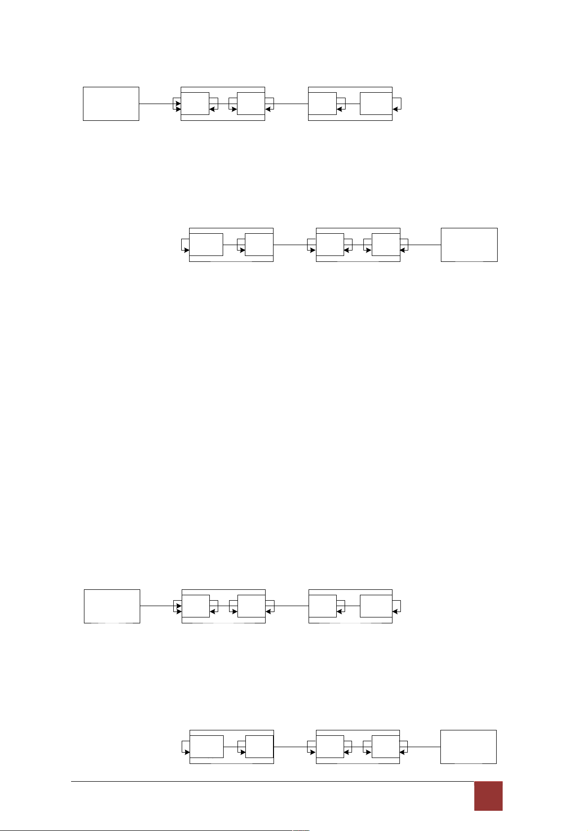
Loopback Define E1 vs E1
STU-C (E1) STU-R (E1)
E1
shdsl
Ld
La Lc
Lb
shdsl E1
Le Lf
STU-C (E1) STU-R
(E1)
E1
shdsl
shdsl E1
Lf
Le
Lb
Lc La Ld
Local Digital
La Local
Lb Remote Line
Lc Remote Payload
Ld Far End Line
Le Far End Payload
Lf
Loopback Define Serial vs Serial
STU-C (Serial) STU-R (Serial)
V.35
shdsl
Ld
La Lc
Lb
shdsl V.35
Le Lf
STU-C (Serial) STU-R
(Serial)
V.35
shdsl
88
Page 93

shdsl V.35
Lf
Le
L
b
Lc La Ld
Local Digital
La Local
Lb Remote Line
Lc Remote Payload
Ld Far End Line
Le Far End Payload
Lf V.54
Loopback Define Fractional E1 vs V35
STU-C (E1) STU-R (V35)
E1
shdsl
Ld
La Lc
Lb
shdsl FPGA
Le L
f
STU-C (V35) STU-R
(E1)
FPGA
shdsl
shdsl E1
Lf
Le
Lb Lc La Ld
Local Digital
La Local
Lb Remote Line
Lc Remote Payload
89
Page 94

Ld Far End Line
Le Far End Payload
Lf
90
Page 95

The product supports Bit Error Rate Testing (BERT). To configure the BERT, move the cursor to
BerTest and press [ENTER] or [RIGHT].
Page 96
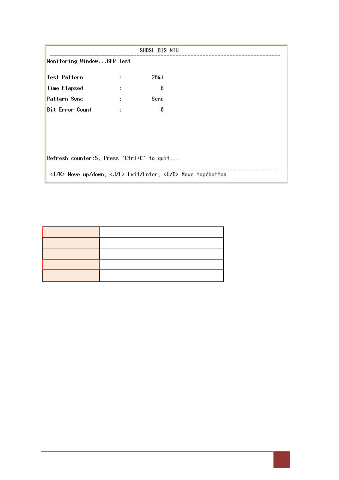
The BER Test screen is as following:
The G.SHDSL Bis NTU includes an internal Bit Error Rate Tester (BERT) for complete testing
of local and remote modem and the link quality without any need for an external test equipment.
This built-in Bit Error Rate Test generator can generates a standard 2047 (211-1) test pattern.
Test Pattern: 2047
Use the standard 2047 (2
1
1
-1) test pattern
Time Elapsed Show the time elapsed count
Pattern Framing Show the linking is sync or no sync
Bit Error Count Show the bit error counter
Refresh counter Page refresh counter
You can press CTRL-C to quit this page anytime.
90
Page 97
4
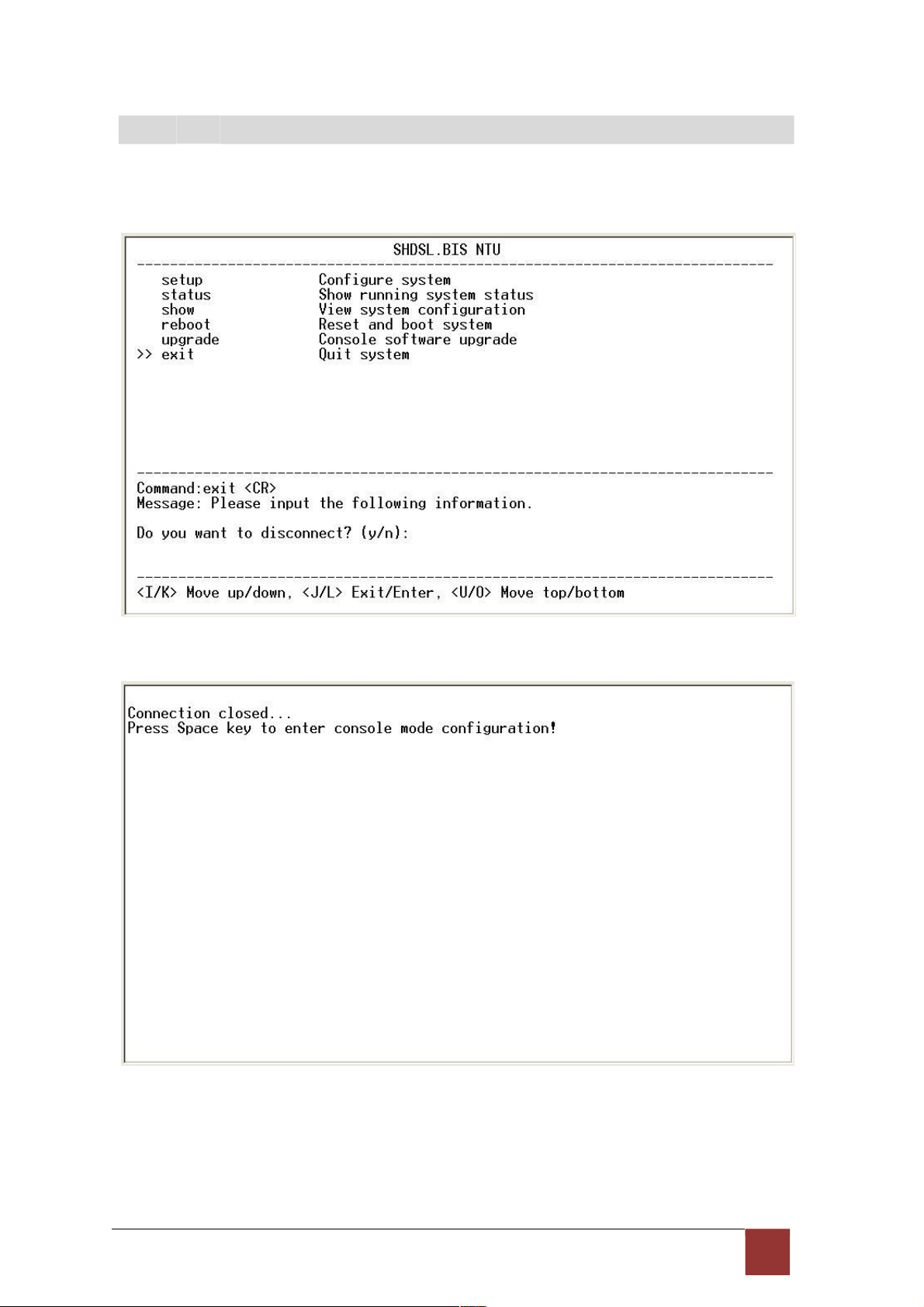
.11 E xit
For exiting the system without saving any configuration, you can use exit command to exit. Select
exit and press [ENTER] or [RIGHT]. Answer y(es) to confirm.
After press [ENTER], the system will be disconnected.
When the system have disconnected, we can see the close screen. You can press Space key to
restart.
91
Page 98

The new login screen will show again, you can type username and password again to enter.
92
Page 99

5. Appendix
5
.1 A bb r ev iat ion
AIS Alarm Indication Signal
AMI Alternate mark inversion
ASYM Asymmetric
ATM Asynchronous Transfer Mode
B8ZS Bipolar with 8 zero substitution
BER Bit error rate
BERT Bit Error Rate Tester
BNC Bayonet Nut Coupling
Bayonet Neill-Concelman
Barrel Nut Connector,
Bayonet Nipple Connector
Bayonet Navy Connector
Baby N Connector
CAS Channel Associated Signaling
CERR CRC Errors
CO Central Office
CPE Customer Premises Equipment
CRC
CRC4
Cyclic redundancy check
Cyclic redundancy check 4 bit
CRS Carrier Sense
CTS Clear to send
DCD Data carrier detect
DCE Data communication equipment
DSL Digital subscriber loop
DSR Data set ready
DSLAM DSL Access Multiplexer
DTE Data terminal equipment
DTR Data terminal ready
E BIT GEN
EOC
Remote End Block Error Bit generation
Embedded operations channel
ES Number of Error second (Errors/Second)
ESF Extended super frame
93
Page 100

ETSI European Telecommunications Standardization Institute
FAS Frame alignment signal
FCS Frame Check Sequence
HDB3 High-Density Bipolar of order 3
HEC Header error check
I/F Interface
ITU International Telecommunication Union
ITU-T ITU-Telecommunication Standardization Sector
LBO Line Build Out
LIU Line Interface Unit
LOC Loss of Connection
LOF Loss of frame
LOS Loss of signal
LOSW Loss of synchronization word
MAS Multi-frame Alignment Sequence (CAS Format)
MFAS Multi-frame Alignment Sequence (CRC4 Format)
NI Network Interface
NRZ Non-Return to Zero
PABX Private Automatic Branch Exchange
PAM Pulse Amplitude Modulation
POTS Plain Old Telephone Service
PRBS Pseudo-Random Bit Sequence
PSD Power spectral density
QRSS Quasi-Random Signal Source
RAI Remote alarm indication
RESYNC Resynchronization
RJ-45 Registered Jack-45
RTS Request to send
RX Receiver
SES Number of Severely error seconds (more than 832 CRC errors /
second. Approximately equivalent to a bit error rate of 1 x 10⁻³.
SF Super Frame
SHDSL Symmetric High-Bitrate Digital Subscriber Loop
SLC Subscriber Loop Carrier
SMF Sub-Multi frame
SNR MARGIN Signal to noise ration margin
STU SHDSL Terminal Unit
94
 Loading...