

Page 1

Fiber Optical Multiplexer
8x E1, 1x Fast Ethernet, Hotline, 1x Fiber optic
XL-FMUX8E1F
User’s Manual
Page 2

Thank you for using XtendLan’s product. This manual provides most of the information; please do read up the
technical setup and safe keep the manual for future usage.
1 Product Description
1.1 Function Description
XTENDLAN Fiber Optical Multiplexer product family provides ideal solutions for building fiber base E1
or T1 networks.
FMUX8E1F is a staff of Fiber Optical Multiplexers, this model it can multiplex to 8 E1 signals for
transmission over an optical fiber, resulting in reaching a longer distance without a repeaters and superior
performance compared to copper media.
FMUX8E1F is the 8E1 point-to-point optical transport equipment that uses the FPGA chips and it is easy
to upgrade. It is single board structure and the largest transmission capacity is 8E1. The outer design use
the standard 19 inches rack, so the volume is little, weight is light and operation is convenient and credit.
8E1 fiber Optical Mulitplexer uses the PDH fiber transmission technologies. The 2M (E1) interfaces can
connect with the exchanger, light loop device and multi-diplexer directly to form the micro, midi or the
special network. Complete alarm function for FMUX8E1F, it is stable and easy to maintenance, install and
small in size. It has one digital service telephone.
Page 3

1.2 Features
Below lists the features for FMUX8E1F:
Offer 8 X 2Mb/s digital interfaces
Up to 8 E1 links on one fiber
Management through Console port
The supervisory control interface implements centralized monitoring and export the monitor and
control information of this port and opposite port.
One link to service telephone for duty contract
90-260VAC & -48VDC power options and the positive and negative of DC-48V can be optional
because there is the self-test circuit for the polarity inside th1e device
Standard 19 inches rack, little volume, light weight, steady capacity and convenient setup
Digital clock recovery circuit and digital smooth DPLL adopted for 2.048Mb/s port
LED indicators
1.3 Application
XtendLan FMUX8E1F can be used a high-speed baseband modem for point to point that connects two DTE
over a lease Line. From Router Æ CSU/DSU Æ FMUX8E1F Æ Fiber opticalÆ FMUX8E1FÆ
CSU/DSUÆ DTE as illustrated in the Following Diagram.
Diagram 1.1
Page 4
1.4 Specification
E1 line Interface
Number of E1 8 E1’s Interface Standard ITU-T G.703
Line Rate 2.048Mbps±50ppm E1 Impedance 120 ohm (balanced)
Line Code HDB3 HDB3 Connector Type RJ-45
Jitter tolerance
Optical Fiber Interface
Wavelength
Light Source MLM Laser Detector PIN Photodiode
System Gain 26 dB (Min.) Input Sensitivity -38dBm (Ber<10e-10)
Line Code Scrambled NRZ Output power -6 dBm
Physical/Electrical
Dimension
Mounting
Power Source 100 – 240 VAC ( 50H/60Hz)
Power consumption
Temperature Range
Relative Humidity
Management
RS485, with the two-string cable, one computer can supervise the 256pair fiber modem. It can be
Better than G.742,G.823
1310nm
Height 44 mm / 1.7 in (1U), Width 485 mm /19
In Depth 160 mm / 6.3 in
Stand-alone,19” inch rack mount, wall mount also available
0°C - 50°C (32° to 122°F)
0% - 90%, non-condensing
Connector Type SC
< 5 W
manage by our SNMP NMS device, which has a RS485 interface.
Timing
Timing derived from incoming E1
Diagnostics Test
Loop-back testing for 8 x E1 (Local and remote)
Loop-back testing for fiber optical (Local and Remote)
Indicators
Local optical signal indications for all E1s.
Remote optical signal receive indication, working and loss.
Loop-back indication.
Alarm indication, on or off.
Power on indication.
Page 5

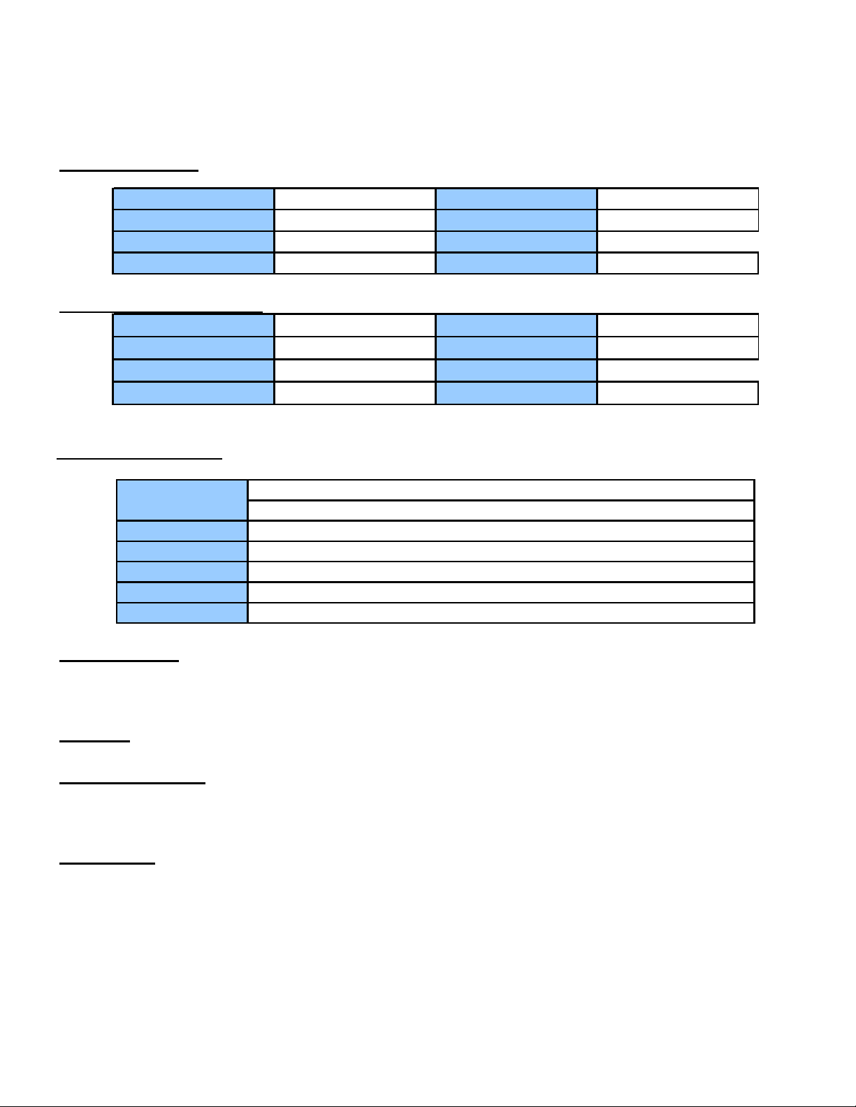
Front panel
From left to right – 1x NMS RS-485 port, LED indicators, diagnostics and phone push buttons, phone line port
RJ-11
Rear panel
From left to right – power switch, power supply port, LAN port RJ-45 10/100Base-TX, fiber optics port SC
duplex connector, 8x RJ-45 balanced E1 port.
Page 6

2 INSTALLATION
2.1 Site Selection
This is a guideline for FMUX8E1F installation. The following list indicates a site selection guideline. User
needs to follow this guideline for the select a proper installation site.
For the FMUX8E1F unit, the location should be part of the Central Office (CO) equipment layout
design. The entrance cable routing should be consider.
The installation should provide a proper room for the adequate ventilation and cable routing at site. At
least 0.5 m should be reserve at the rear of the unit for the human access, cable, and airflow.
The site should provide a stable environment. The Ops Area (Operating Area) should be free from
extremes temperature, humidity, shock and vibration.
Do not expose the unit under the rain because FMUX8E1F is not a waterproof unit.
Relative humidity should stay between 0 and 95%.
Survey the site (power supply) before install the unit.
Page 7

2.2 Mechanical Installation
FMUX8E1F is a desktop and 19” rack mount unit. Unit supports AC power supply.
2.2.1 Light indicators
Name Color Status Describe
1 LOS1 Red Active E1 port 1 loss
2 LOS2 Red Active E1 port 2 loss
3 LOS3 Red Active E1 port 3 loss
4 LOS4 Red Active E1 port 4 loss
5 LOS5 Red Active E1 port 5 loss
6 LOS6 Red Active E1 port 6 loss
7 LOS7 Red Active E1 port 7 loss
8 LOS8 Red Active E1 port 8 loss
9E6RedActive
10 E3 Red Active
11 OPLOS Red Active Optical signal Lost
12 OPLOF Red Active Optical SYNC loss
13 LE Red Active Local device have any error(E1 and Opt)
14 RE Red Active Remote device have any error(E1 and Opt)
15 PWR Green Active Power on
Remark:Equipment Can Monitor the remote device
LRS
16 LNK/ACT
17 FDX
18 SPD
UP
DOWN
If the Device Have Lan Interface
Green Active
Green Active
Green Active
The led indicate local device status
The Led indicate remote device status
ON :full duplex,OFF:half duplex
Optical BER≥10-6
Optical BER≥10-3
LAN Link and Active
ON :100M,OFF:10M
Page 8

2.2.2 Front panel DIP definition:
Bit 1-4 ( RLOOP1-4 ): 1-8E1 remote loop.
RLOOP1-4 as 1 to 8 port’s E1 it is to indicate loop back.
If the RLOOP1 is ON, this means that at the far end the is doing a E1 loop-back
In the following table 0 means ON,1 means OFF
The Remote NO x E1 Loop Bit1 Bit2 Bit3 Bit4
1000
2001
3001
4010
5010
6011
7011
8100
ALL 8E1 Loop
Remark: Bit 5-8: Reserved
000 0
2.2.3 Front panel PUSH button definition:
In the front panel are four push buttons. It is MSK, SMSK, LRS, PH
The function described following table
1
0
1
0
1
0
1
0
Page 9

PUSH OFF (button up) ON (button down)
MAK Normal LED Display LED Alarm OFF
SMSK Sound Alarm Sound Alarm ShutDown
LRS LED Means Local LED means Remote
PH Hot line phone not used use Hot line phone
2.2.4 Hot line phone
Hot line phone, not occupy 2Mbps channel transmission.
On the front panel there is a “PH” button, press on the “PH” button on the remote site it will sound. To answer
it the remote site just need to press the “PH” button on the remote unit, the alarm will cut off and just plug in
the phone both side able to do the communication.
Setting of the manage phone.
It does not occupy the 2M circuits!
2.2.5 Ethernet
FMUX8E1F can offer a channel for 10/100M, full/duplex auto-negotiation LAN interface, support VLAN
protocol, this interface can continuous learn MAC addresses in the LAN that connected with it, and send the
address as frame in another LAN. Transparence to TCP/IP protocol, offers security connection between
different equipments in the network, used widely in network connection and monitor between WAN and
LAN.
10/100 Base-T Ethernet port parameter
Rate: 10M or 100M, full/semi duplex auto-negotiation
Ethernet rate in optical line: 2.048 Kbps
.
Page 10

Protocol: support IEEE 802.3, IEEE 802.1Q(VLAN)
MAC address table: can learn 4096 MAC address
Ethernet buffer memory: 64 Mbits SDRAM
Physical interface: RJ45 slot, support AUTO-MDIX
Ethernet operating diagram:
2.2.7 Power supply
FMUX8E1F Fiber Optical Multiplexer supports 3 type powers: AC220V, -48V and +24V. If the power of
DC-48V is used, the positive and negative terminal can be optional because there is the self-test circuit for the
polarity inside the Fiber Optical Multiplexer.
3 Operation
3.1 Equipment installation
After unpacking and before installation, make sure checking the following:
Make sure the package is well. If the package is damaged, contact service office of XTENDLAN
quickly for solution.
Check the package according to the product list, if find equipment severe damaged or lack of some
components, please contact installation worker or service office of XTENDLAN.
Check whether the equipment type is meet with the type you ordered.
Check whether the component is integrity.
Check the power supply type.
3.1.2 Quick installation
Fasten the Equipment in 19 inch. rack with the screws in the equipment package.
Use reliable ground connection at GND point of the equipment
Page 11

Use power tab to connect power according to the manual, don’t exchange the polarities.
Create user equipment connecting wire according to your demand (2M, V.35 and 10 Base-T), then
connected, don’t exchange receive and transfer wires.
Connect receive and transfer optical with optical receive and transfer port of the equipment. Don’t
exchange receive and transfer wire, make sure the optical fiber head is clean, insert optical jumper,
make sure connection well. (fiber bending radius≥50 mm)
Use multimeter to test power polarity and voltage, make sure it match with equipment requirement.
After complete installation and make sure it’s ok, power on the switch. Check indicator light meet
with practice situation (see related part of manual).
A clean, steady environment and firm installation should provided for independent or wall hanging
equipment.
3.1.3 Cautions about installation
Avoid severe libration and mechanical damage during the process of transfer and installation.
Arrange fiber appropriately, fiber bending radius≥50 mm.
Check voltage and polarity meet with back panel, or it will cause permanent damage to the
equipment.
Fiber connector can’t contaminate, wipe optical fiber head slightly using alcohol, or it will affect
transmission. If the fiber connector not butt joint well, it may be cause power decline, adjust fiber
connector according to practical situation.
The installation position should convenience for personal pass and equipment movement.
The environment should dry, clean and ventilation well.
Essential static-protective is needed during the installation and maintenance, ground the chassis to
increase anti-interference capability and prevent lightning strike. Before use the equipment,
independence work ground and protect ground should provided, make sure it ground well.
3.2 Power on the equipment
Check indicators and alarms according to manual after power on.
If both local and remote work well, fiber interface connect ok, the alarm light OPLOS and OPLOF
off, POWER indicator light is green.
Light LOSX (X=1-8) is red and voice alarm is on because of not connecting E1 signal. After
connect E1 signal, light LOSX (X=1-8) will off, voice alarm will off until all light LOSX is off.
Page 12

Branch shield: shield no using branch alarm, no red light is on when all alarm is off.
Hot line phone: after Fiber Optical Multiplexer works normally, insert microphone to hot line phone
port, press button PHONE to call remote user, then can communication after the remote user press
button PHONE and hold up the microphone. Buzzer rings when remote terminal call local terminal,
press button PHONE and hold up microphone, then communicate with remote terminal. Back the
button PHONE to norm after communication is completed.
Branch loop: when system work normally and no branch alarm happen, loop test is available with
SW. Put the SW switch to ON in local terminal, can control remote corresponding 2 Mb/s branch to
loop, then can test corresponding output signal at local 2 Mb/s output port. Use this function you
can realize loop of all the branches, and it’s easy for detect.
Use bit error instrument to analyzing performance of 2M branch, and record it.
Close voice alarm: voice alarm on when following situation happened:
A. Optical disconnected cause OPLOS alarm.
B. Signal not steady cause OPLOF alarm.
C. Some branches not use and not shielded.
Push down SW5 at local terminal, can control closing voice alarm.
Note: After failure is removed, set the button to norm, validate the alarm function
3.3 Troubleshooting
Best status is configured to this equipment before out of factory, all the functional interfaces are at the front and
back panel, don’t open the chassis yourself. If have failure, you can determine the range of failure using single
loop, and contact our corporation.
The following table list common failure and alarm, the reason may cause these alarm and solution to this alarm
for you to reference.
Equipment alarm and corresponding solution
Page 13

Alarm Possible reason Solution
1 POWER off not power on
2OPLOS on
3OPLOF on
4 E1 alarm Not receive 2M signal Check wire; receive and transfer are exchanged
5 Voice alarm Local alarm happened Shield when process failure
Not receive optical
signal
Not receive normal
frame signal
Receive signal not steady,check fiber line
Power connect not well, polarity
exchanged
Optical disconnected; remote having no
optical output
and equipment
 Loading...