

Page 1

FMUX- 2020
PCM Multiplexer
Operation Manual
Page 2

Content
FMUX 2020......................................................................................................................1
PCM Multiplexer......................................................................................................1
1
Summary
...........................................................................................................................................................4
2. Main technical
character
..........................................................................................................................5
3. Hardware
Characteristic
...........................................................................................................................6
3.1 Fundamental .............................................................................................................................................6
3.2 Mechanical Framework..........................................................................................................................7
3.3 Main technical Parameter ......................................................................................................................8
3.3.1 E1 interface........................................................................................ 8
3.3.2 Audio interface...................................................................................8
3.3.3 Data interface..................................................................................... 8
3.3.4 Working condition ............................................................................. 8
4.Network
application
....................................................................................................................................8
5. Installation
explain
......................................................................................................................................9
5.1 Check whether the equipment and spare part are all right..............................................................9
5.3 Connection of 2M signal........................................................................................................................9
5.4 Connection of network interface (RS232) cable.............................................................................10
5.5 V.24 data interface .............................................................................. 10
Table 2 Reference of synchronous V24 signal cable connection wire.............................................. 11
5.7 10Base-T Ethernet data interface .......................................................................................................13
5.8 X.50 data interface ................................................................................................................................13
5.9 64kb/s G703 data interface..................................................................................................................14
5.10 UIF data interface................................................................................................................................14
5.11 2-wire audio interface.........................................................................................................................14
5.12 EM audio interface..............................................................................................................................15
5.13 2/4-wire magneto interface................................................................................................................15
5.14 2Mb/s interface ....................................................................................................................................15
6. Malfunction diagnosis and
operation
...............................................................................................16
6.1 Panel indicator light ..............................................................................................................................16
6.2 Halting ring operation...........................................................................................................................18
6.3 System configuration ............................................................................................................................18
6.3.1 NMS address configuration ............................................................. 18
6.3.2 System configuration ....................................................................... 18
6.3.2.1 Configuration of MCT board ................................................................................................18
6.3.2.2 Configuration of 10Base-T Ethernet board........................................................................18
6.3.2.3 Configuration of 2M board...................................................................................................19
Page 3

6.3.2.4 Configuration of UTF board .................................................................................................19
6.3.2.5 Configuration of EM board ..................................................................................................19
6.3.2.6 Configuration of magneto interface board ............................................................................19
6.3.2.7 Configuration of V.35 board .................................................................................................20
6.3.2.8 Configuration of HOT board ................................................................................................20
7 Network management
system
...............................................................................................................20
7.1 Connection mode...................................................................................................................................20
7.3 Main function and operation introduction ........................................................................................21
Page 4

1 Summary
Nowadays, optical fiber communication and standard interface E1 are widely used, how to solve
audio, low-speed data, ISDN, and computer access with relatively low cost and flexibly have been a bothered
problem to special network engineer. Based on widely market investigation and absorb advantages of
many manufactures,
FMUX2020 PCM multiplexer( hereinafter shortly refer to FMUX2020) is one of FMUX series
transmission network products. It can provide users with the combination of 2-wire loop interface, 4-wire
E/M interface, RS-232 asynchronous interface, V.35 (or G.703 synchronous data interface), ISDN-U
interface, and 10/100M Ethernet interface etc. with total capacity up to 2.048 Mb/s.
GK FMUX 2020 Intelligent Multiplexer is highly integrated and designed with up-to-date large-scale
IC (Integrated Circuit). It features advanced network management system and can be maintained easily.
The company owns its self-developed IP(Intelligence Property) rights and therefore can satisfy clients’
special requirements. In terms of network configuration, it can be used in point-to-point or chain-like network.
Page 5

2. Main technical character
a) Providing double E1 port ( both east direction and west), supporting
75Ωcoaxi
al or 120Ωbalance
cableconn
ectionand
self-co
nne
ctinwhe npowers
upply
is cu
t off
.
b) Double E1 port (both A and B direction) is designed for the networks requiring the add/drop
multiplexing of sub-rate signals. After add/drop multiplexing or insert part of sub-rate signals,
the E1 signal from A direction can continue to be transmitted to B direction thus completing
the relay function.
c) Inserted board structure can provide abundant voice interface by choose different board:
1) LS(Loop Subscriber)interface, also called primary station interface or 2-wire
subscriber loop interface, is connected with telephone set. 4 channels of each
board.
2) LE(Loop Exchange)interface, also called slave station interface or 2-wire loop
exchange interface, is connected with the exchange;4 channels of each board.
3) E/M 4-wire interface, E/M 2/4-wire audio interface board includes E/M signaling,
4 channels of each board. Switch of 2/4-wire can configured by switch in the
board, and level can be modulated by network management, also 4 channels of
each board.
4) Magneto interface, used in dedicated line telephone, provides ringer and the test of
ringing current, 4 channels of each board.
5) Hotline interface can provide two kinds of voice operation: Hotline mode,
realizing point –to –point calls and communication of two terminals. Its
loop-circuit function is as the same as LS board, realizing choice of the two mode
via jumper in the board, 4channels of each board.
d) Providing abundant data interface:
1) V.35 synchronous data interface with a rate of N 64kb/s,up to a maximum of
1.984Mb/s, providing direct connection with DTE or DCE equipment, 2 channels
of each board.
2) G.703 64 kb/s synchronous data interface, 4channels of each board.
3) V.24 synchronous data interface with a rate of 2.4k, 4.8k, 9.6k, 19.2k, 38.4k,
64kb/s. Synchronous or asynchronous mode, X.50 multiplexing protocol or direct
sample of sub-rate, supporting direct connection with DTE or DCE equipment. 4
channels of each V.24 board, while 5 channels of each X.50 board.
4) Ethernet interface, providing 10/100M Ethernet bridge function, and 1 channel of
each board.
5) U interface (ISDN), maximal data transmission rate up to 128kb/s, 2 channels of
each board.
(e) With the connection to the PC through serial interface RS-232, the FMUX 2020 Intelligent
Multiplexer can realize the network management. The management functions include alarm and
status display, interface type and circuit configuration, as well as loop back test etc. Operating
system WIN9X/NT is used in PC and a single PC can management as many as 99 terminals.
Page 6
2-wire LoopSubscriber
Interfac
e L
S
2/4wire audio
E1 Interface
No-signaling
Audi
o
Interfaceor
E& M
Interfa
ce
2-wire Loop Exchange
interfac
e L
E
V.24/V.28
E1 Interface
19.2kb/s
RS-232
Asynchronous
Dat
a
G.70364kb/sSynchr
ono
us
DataInterface
V.35/V.24S
ynchrono usDat
a
Interfac
e
ISDN-BRI(2B+D)Interface
RS-232
10Base-TInt
erface
MainControl
Board
:
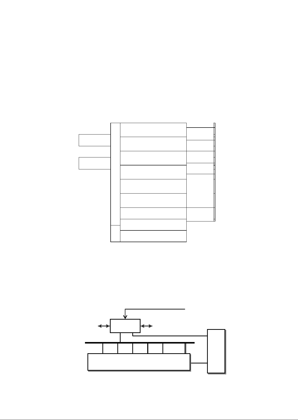
3. Hardware Characteristic
3.1 Fundamental
FMUX 2020 2Mb/s Intelligent Multiplexer is a kind of primary group equipment with standard
pulse code modulation (PCM), compliant with GB6879-86, “Technical Requirements for
2048Kbit/s 30 Channels PCM Multiplexer Equipment”, and supporting the multiplexing of various
sub-rate signals. Please refer to figure.1.
(
:
;
HUB
Network
Management
Figure 1 Functional Block
Diagram
The collective connection show as figure 2, main control board and interface board connected via PCM high
speed bus, within signal PCLK, DR, DX, FS, to complete transmission of voice and data signal. Control of
interface board is realized by AD-BUS, this information include: interface board type, running state, CAS,
add/drop multiplexing of sub-rate signals etc. The location of interface board LN can be inserted in
any type of audio board. Monitor system identify the interface board type automatically and
configure standard configuration of time slot.
RS232
:
2Mb/s
MCB
Network management background
2Mb/s
Power
PCLK DR DX FS AD-BUS
supply
board
Interface
board
Page 7

Figure 2 Collective connection
diagram
3.2 Mechanical Framework
The box dimension is
345mm×200mm×210mm,and
three options for installation are
provided:19” frame (hole spacing: 461.5mm), European standard frame (hole spacing: 515mm) and
wall mounting. Every unit has 13 circuit boards if fully equipped and all signal lines are connected
to the front panel.
M
C
T
LNLNLNLNLNLNLNLNLNLNLNP
O
W
MCT--Main Control Board, LN--Line Interface Board, PWR--Power Supply
Board(which can be inserted in the position of LN, used for stand-by)
Figure 3 Mechanical Framework of FMUX2020
multiplexer
Figure 4a) 19” frame installation diagram Figure 4b) European standard
frame
installation
diagram
Page 8

V
.
2
4
V
.
3
5
E
x
c
h
a
ng
e
r
Figure 5 Wall mounting
diagram
Figure 4 is the installation diagram on two different width self of the same kind bend angle bar (Installation angle
and direction of bend angle bar are different). Figure 5 is wall mounting diagram.
3.3 Main technical Parameter
3.3.1 E1
interface
a) Standard rate: 2048kb/s, capacitance difference
±50
10-6.
b) Interface type: A.
75Ω
unbalance, HDB3 code; B.
120Ω
balance, HDB3 code.
3.3.2 Audio
interface
a) Impedance:
600
Ω
b)Arule
condensed coding;
c)Audiomodulationr
ang
e:
1) Audio 2-wire: Receiving signal level 0 dBr~-7.5dBr, sending signal level 0 dBr~-7.5dBr
2) Audio 4-wire: Receiving signal level +2 dBr~-13dBr, sending signal level +1 dBr~-14dBr.
3.3.3 Data
interface
a) V.24 data interface, rate below 64kb/s, synchronous or asynchronous, X.50 multiplexing;
b) G.703 64kb/s synchronous data interface;
c) V.35 synchronous interface, rate is N 64kb/s, maximum is up to 1.984Mb/s;
d) Data line ISDN-U interface, rate is 128kb/s;
e) 10Base-T Ethernet interface, rate is 10/100Mb/s.
3.3.4 Working
condition
a) Working voltage :D.C
±48×(1±20%)V
or A.C 220×(1±20%)V;
b) Relative humidity: 10%-90%, not condensation;
c) Environmental temperature: 0 C 40 C;
d) Storing temperature: -30 C 60 C;
e) atmospheric pressure: 86kPa~106kPa;
f) power consume:≤
40W
4. Network application
Show as figure 6:
2Mb/s
FMUX2020
multiplexer
RS232
PC
Page 9
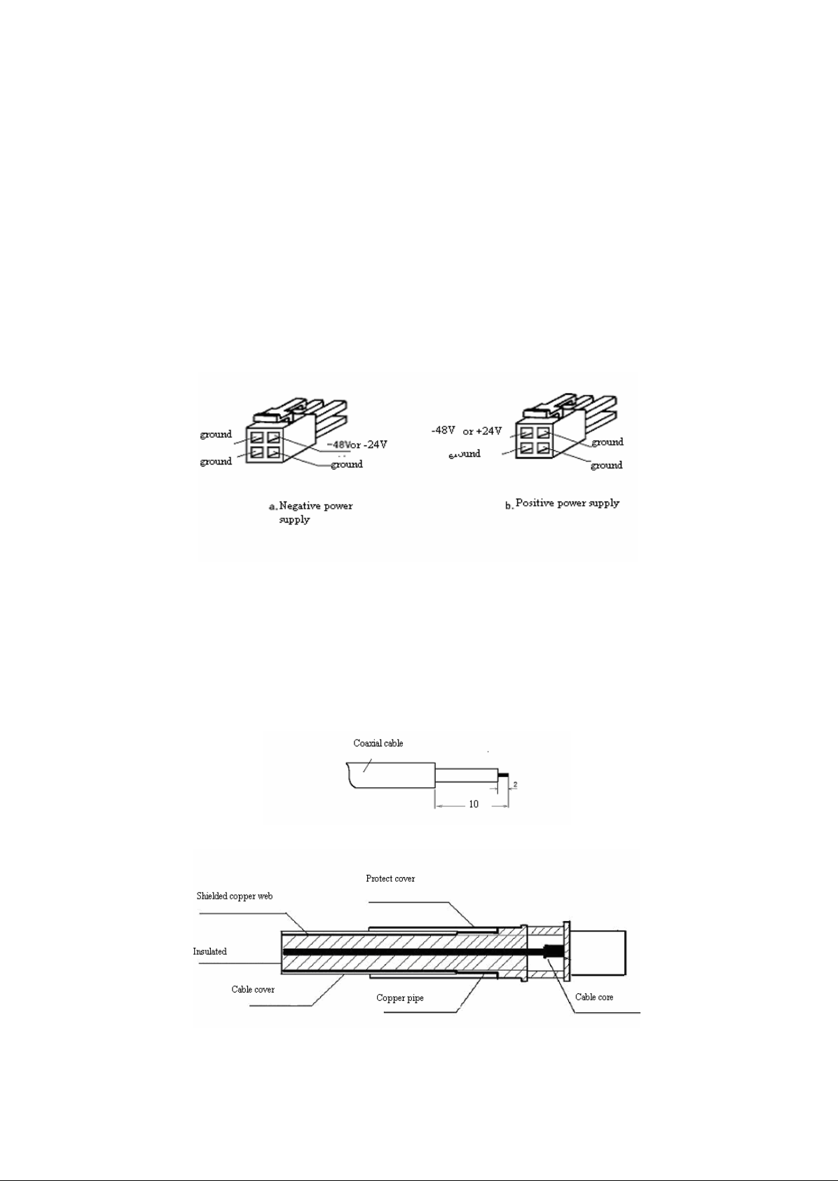
Figure 6 Connection diagram of FMUX2020 multiplexer network
configuration
FMUX2020 multiplexer connect with PC via RS232 serial interface to realize network management
function. Multiplexer extract 2Mb/s signal which transmitted by base station, providing V.35 and V.24 interface.
5. Installation explain
5.1 Check whether the equipment and spare part are all right
Fixed power supply plug on +48V/+24V or –48V/-24V power supply wire followed as figure 7, and then insert
it in power supply jack; AC power supply jack be inserted in directly.
Figure 7 Connection of power supply
wire
5.3 Connection of 2M signal
2Mb/s interface connect with the outside via coaxial cable, when exterior wire is 75Ωcoaxialcable,I1 and
O 1meansi
nputandoutputof2Mb/ssignalofthefirstc
hann el(orcalledAdirection)
,whileI2
and
O 2
me ansinputandoutputof2Mb/ssignalofthe
second c
hannel(orcalledBdirection).Coaxialcable
configurationis shownasfigure
7 andfigur
e 8
.
Cut cover of coaxial
cable
Figure 8 Facture of coaxial cable
connector
Page 10

RJ45
When exterior wire is 120Ωcoaxial cable, connecting with the outside via DB9 connection jack, show as figure
9.
E1
1,6
2,7
CH1 2M/b 120
FMUX2020
3,8
4,9
5
CH2 2M/b 120
9
Ground line
Figure 9 Connection of 2M/b
120Ωcoaxial
cable
5.4 Connection of network interface (RS232) cable
Show as figure 10
9 3 9 3 3
8 2 8 2 2
5 5 5 5 5
FMUX2020 multiplexer FMUX2020 multiplexer PC
5.5 V.24 data interface
Figure 10 Connection of network interface (RS232)
cable
Each V24-RS232 interface board of FMUX2020 multiplexer can provide 4 channels of RS232 data interface at
most, connecting with exterior wire via RJ45 connection jack, supporting synchronous and asynchronous
interface. Asynchronous data transmitted with sample mode, maximal rate up to 19.2kb/s, and each channel occupy
a 64kb/s time slot; Synchronous data rate is 64kb/s. Every kinds of data format is configured by network
management software.
Signal connection of RJ45 connection jack show as figure 9:
Synchronous Asynchronous
1
0 output Control output TXCTL
2
DCD output DCD output
3
Not have used X Control input RXCTL
4
Ground line Ground line
5
Data output RXD Data output RXD
6
Data input TXD Data input TXD
7
Clock input TXC Not have used X
8
Clock output RXC 0 output
Figure 11 Connection of V.24
signal
Page 11

V24-RS232 interface can connected with synchronous or asynchronous DTE or DCE port, please refer to table 2
and table 3.
Table 2 Reference of synchronous V24 signal cable connection
wire
Signal
Name
DTE
Equipment
V24 port DB25S
Connection
mode
FMUX-RJ45
Connection
mode
DCE
Equipment
V24 port
DB25P
Signal
Name
TXD
2
TXD63
RXD
RXD
3
RXD52
TXD
GND
7
Ground47
GND
TTC
24
TXC717
RC
TC
15
RXC824
TTC
RC
17
CTS
5
0 output120
DTR
DSR66
DSR
DTR205
CTS
RTS48
DCD
DCD
8
DCD24
RTS
Table 3 Reference of asynchronous RS232 signal cable connection wire (DSR/DTR follow control
mode)
Signal
Name
DTE
Equipment
Connection
mode
FMUX
Connection
mode
DCE
Equipment
Signal
Name
DB9S
DB25S
RJ45
DB9P
DB25P
TXD32
TXD623RXD
RXD23
RXD532TXD
GND
5
1,7
Ground45
1,7
GND
DTR420
TXCTL366DSR
DSR66
RXCTL
1420
DTR
CTS85
RXC874RTS
RTS7485
CTS
DC D18
DCD218DC D
5.6 V.35 data
interface
Each V.35 interface board of FMUX2020 multiplexer can provide 2 channels of V.35 synchronous data
interface, connecting with exterior wire via DB15 negative jack, supportingN×64kb/s (maximal rate up to
1984kb/s),
and occupying N 64kb/s time slot. Occupied time slot and rate of V.35 interface are configured by NMS.
Table 4 and table 5 is corresponding connect pins. CH1 and CH2 means the first channel and the second
channel synchronous data interface.
Table 4 Connection with DTE equipment (DCE
port)
15 Pin No.
Name
Direction
Explanation
Corresponding
Level
Page 12

V.35 Terminal
1
GND
Dual
direction
Protect
ground
pin(shiel
d)
A
2
SDA
To PCM
Send data
A
P
V.35
9
SDB
To PCM
Send data
B
S
V.35
5
CTS
From PCM
Sendi
ng
i
s
gettingready
D
V.28
12
DSR
From PCM
PC Misgetting
ready
E
V.28
12
DCD
From PCM
PCM receiving is
normal
F
V.28
8
GND
Dual
direction
Protect
ground
pin(shiel
d)
B
4
RDA
From PCM
Receive
data
A
R
V.35
11
RDB
From PCM
Receive
data
B
T
V.35
14
SCA
From PCM
Transmitti
ng
clock
A
Y
V.35
15
SCB
From PCM
Transmitti
ng
clock
B
AA
V.35
6
RCA
From PCM
Receivingcloc
k
A
V
V.35
13
RCB
From PCM
Receivingcloc
k
B
X
V.35
3
SCEA
To PCM
Exterior
synchronizatio
n
clock
A
U
V.35
10
SCEB
To PCM
Exterior
synchronizatio
n
clock
B
W
V.35
N
ote:PCM m
eansFMUX2020multiplexer
andpinsnot belined outneedn’tt
o be
co
nnected.
Table 5 Connection with DCE equipment (DTE
port)
15 Pin No.
Name
Direction
Explanation
Corresponding
V.35 Terminal
Level
1
GND
Dual
direction
Protect
ground
pin(shiel
d)
A
2
RDA
To PCM
Receive
data
A
R
V.35
9
RDB
To PCM
Receive
data
B
T
V.35
4
SDA
From PCM
Send data
A
P
V.35
11
SDB
From PCM
Send data
A
S
V.35
5
DTR
From PCM
Data terminal is
getting ready
H
V.28
12
RTS
From PCM
Requiring sending
C
V.28
8
GND
Dual
direction
Si
gna
l
ground
Loop-circuit
B
Page 13

6
SCEA
From PCM
Exterior
synchronizatio
n
clock
A
U
V.35
13
SCEB
From PCM
Exterior
synchronizatio
n
clock
A
W
V.35
3
RCA
To PCM
Receivingcloc
k
A
V
V.35
10
RCB
To PCM
Receivingcloc
k
B
X
V.35
Note:PCM
me ans
FMUX2020multiplexer
andpinsnotbelined outneed n’tt
o
be c
onn ecte
d.
5.7 10Base-T Ethernet data interface
The main Ethernet interface function is completed by FMUX2020-BRGS board as model, insert it in
the extending slot of FMUX2020-ET board. 10Base-T Ethernet interface, occupying N 64Kb/s
time slot,
connecting to LAN with twisted-pair lines, and conforming to IEEE802.3 standard. It is composed
of Ethernet interface processing unit (EIF), memory unit (RAM), multiplexing and demultiplexing
unit (MUX&DEMUX) and control unit MCU.
The 3rdand 6thpins of RJ45 connector are used for data input of the Ethernet interface, the 1
st
and 2ndpins for data output. Ethernet interface of V2040A is configured as DTE port. Cable should
be crossed (3 and 6 cross with 1 and 2) when connected with DTE equipment (such as PC), while
direct communicating cable can be used when connected with DCE equipment (such as HUB port).
Show as figure12.
V2040 RJ45 DTE V2040 RJ45 DCE
1 1 1 1
2 2 2 2
3 3 3 3
6 6 6 6
Figure 12 10Base-T Ethernet interface connection wire
diagram
5.8 X.50 data interface
Each X.50 interface board provides 5 channels of V.24 synchronous X.50 data interfaces, all of
which are connected with outside line through DB37 male and female connectors or RJ45 jack, and
the supported data rates include 2.4kb/s, 4.8kb/s, 9.6k kb/s, 19.2k kb/s, 38.4k kb/s. The occupied
time slot varies with bandwidth. The time slot and interface rate is controlled by the network
management system. Default configured as asynchronous 9.6k, and each channel occupy a time slot
phase.
X.50 interface is V.24 interface, and connection method is as the same as V.24 interface board.
Please reference to figure 9, table 2 and table 3.
Page 14

5.9 64kb/s G703 data interface
Each 64kb/s G.703 data interface board can provides as many as 4 channels of 64 kb/s data
interface, all connected with outside lines through DB25 female connector. Each channel occupies a
64 kb/s time slot. The indicator CH1 ~ Ch4 indicates the data input status of the corresponding
64kb/s channel. The signal terminals are shown in Table 6.
Table 6 Signal connection of 64kb/s G703 data interface board
CH1
CH2
CH3
CH4
Input
12,24
9,21
6,18
3,15
Output
13,25
10,22
7,19
4,16
5.10 UIF data interface
Each UIF data interface board can provide two U interfaces of 2B+D data, which is connected
to network termination (NT) and line termination (LT). U interface of the two terminals is
communicated, one terminal should be configured as LT, and another should be configured as NT.
LT interface synchronize on clock of PCM system; NT port can be sub-rate clock to synchronize U
interface line of PCM system.
U interface connect with exterior wire via 2-wire metal wire, and tie-in is middle two-core wire
(3 and 4) of RJ12 jack, as the same as standard telephone wire tie-in. Reference to figure 13.
1 2 3 4 5 6
Figure 13 U interface
5.11 2-wire audio interface
2-wire audio interface include LS, HOT, LE and magneto interface, each board having 4
channels and connected with outside lines through DB25-pin female connector. The 4 indicators
indicate the signaling status of the channel 1 to channel 4 respectively.
a) LS/HOT interface board: 2-wire Loop Subscriber interface, or hotline interface,
directly connected to telephone set to complete D/A and A/D conversion,
2-wire/4-wire conversion, ringing, generating ringing signal and test of hook state etc.
Indicator light of LS board lighting means picking state, and channel is being
occupied.
b) LE interface board: 2-wire Loop Exchange interface, directly connected to exchange to
complete D/A and A/D conversion, 2-wire/4-wire conversion, ringing test, polarity
detecting and generating hook state etc. Indicator light of LE board lighting means
hooking on state of remote terminal, and channel is being occupied.
c) Magneto interface board: connected to magneto telephone set to complete D/A and
A/D conversion, 2-wire/4-wire conversion, generating ringing, test of ringing current,
etc. Signaling can be configured as CAS or audio 2100Hz signaling, and configured by
Page 15

J1 switch in the board. CAS means convert ringing signal (16~25Hz) to digital CAS A
to transmit. 2100Hz signaling means convert ringing signal (16~25Hz) to audio
2100Hz to transmit. Indicator light of MS board lighting represent ringing state.
Connection of 2-wire audio interface reference to table 7.
Table 7 2-wire loop audio interface connection
terminal
CH1CH2CH3CH4
13,25
10,22
7,19
4,16
5.12 EM audio interface
E&M 2-wire/4-wire audio interface board contains E&M signaling. Each board has 4 channels of interface
connected with outside lines through DB25-pin connector. The 4 indicators lights indicate the signaling status of
the channel 1 to channel 4 respectively. E represents input line while M represents output line. ALL ground lines
are connected to terminal 1. Connecting with the other transmission equipment should note definition of E and M
line, please reference to table 8.
Table 8 connection Terminals of E&M 2-wire/4-wire Audio
Interface
CH1
CH2
CH3
CH4
4-wire
Input
12,24
9,21
6,18
3,15
Output
13,25
10,22
7,19
4,16
2-wire
13,25
10,22
7,19
4,16
E line11852
M line
232017
14
Ground lines
1
5.13 2/4-wire magneto interface
Having the same function of MS interface board in 2-wire mode. Completing D/A, A/D conversion,
2-wire/4-wire conversion, generating ringing, test of ringing current. J1 switch in the board
configure signaling mode, indictor light lighting means ringing state. Function of 4-wire mode is as
the same as EM audio interface board without E/M signaling. 2/4-wire switch configuration, level
modulation, and audio terminal connection (reference to table 8) are completely as the same as EM
audio interface board.
5.14 2Mb/s interface
2M/S interface board use for extracting time slot between mobile base station and exchange and providing
data transmission. Each board has two 2Mb/s interface, can complete base station time slot extracting of one
direction, and can extract two time slot of 2Mb/s interface beside of base station, then concentrate them in 2Mb/s
interface of MCT board. These two time slot be called as channel 1 and channel 2, and can reach different 2Mb/s
interface (A direction or B direction) of MCT board. FMUX2020 multiplexer which use 2Mb/s interface usually
choose a 2Mb/s from exchange as exterior synchronizing clock. Reference to figure 13.
Page 16

Adirection 2Mb/s
B direction 2Mb/s
MCT
Board
Exchange
CH1
CH2
2Mb/s
Board
Base station
FMUX2020 multiplexer
Figure 13 2Mb/s interface board used for extracting time
slot
6. Malfunction diagnosis and operation
6.1 Panel indicator light
FMUX2020 multiplexer has consummate malfunction alarm function, and indicate working state
through indicator lights of front panel.
Table 9 Panel indicator lights of FMUX2020
multiplexer
Symbol
Color
Meaning
Remark
PW
R
+5
V
GreenFlashingme an sworkingisnormal
RING
GreenFlashingmeansringingcu
rrentoutputisnormal
AL
M
RedLighting
me an spowers
upplyboardisalarming
V.35
CH 1
~
C
H2
TDGr
eenV.35interfacereceiving/transmitting data(D
TE
port
outputor
D C Eportinput
)
Flashing
averagely in 1
second means
looping
RDGr
een
V.35interfacetransmittingdata(DTEportinputor
D C Eportoutput)
V.24
CH1~CH4
Green
Ligh
tingme anschan nelhas
V24si
gnalinp
uttin
g.
Indicatorlightflashaveragelyin1secondmeansV24
port
islooping.Andindicatorlightfla
sh
3 timesinsuccessionwithin4 secondsmeansX.50
framelosesynchronism.
X.50
CH1~CH5
Green
Lighting
me anschannelhas
V24si
gnalinputting.
Indicatorlightflashaveragelyin1secondmeansV24
port
islooping.Andindicatorlightfla
sh
3 timesinsuccessionwithin4 secondsmeansX.50
framelosesynchronism.
Page 17

G.703
CH1~CH4
GreenLightingme anshavingdatainputandchann
el
CH1~
C H4arebei
ng occupied
E TH E
R
CO
L
RedLighting
me an sco
llisionofnetwork.
LINK
GreenLightingm
eansEthernetinterfaceco
nne
ctionis
normal.
TX
D
GreenLightingme ansEthernetportistransmitti
ng
data
.
RX
D
GreenLightingmeans
Ethernetportisreceiving data.
LN
a
u
d
i
o
LS
CH1~CH4
Green
Lighting
me an slocalterminalisin pickstate,
and
ch
annelC
H 1~C
H 4ar
e being occupied
.
LE
CH1~CH4
Green
Lighting
me an sremoteLSisin pick state,
and
c
hannelCH1~CH 4
arebeingoccupie
d.
E
&M
CH1~CH4
GreenLightingme anssignalingstat
e ofMline(
output)
ofE/Mportisoccupying(outputis0)
MS
CH1~CH4
Green
Lightingmeansringingstate,and c
hannelCH1~
C H 4
arebeingoccupied
.
H
OT
CH1~CH4
GreenLightingme an slocalterminalisin pick state,
and
ch
annelC
H 1~C
H 4ar
e being occupied
.
UI
F
C
H 1
~
C
H2
A CTGr
eenLightingme an s Uinterfaceisnormal.
Continuous table
9
Symbol
Color
Meaning
Remark
U
IF
C
H 1
~
C
H2
LFARed
LightingmeansUinterfacealarmoflosing
synchronism,
andwireinterfaceconnectio
n
isabnorma
l.
M
C
T
/
2
M
A direction
2M(I1,O1)
LIS
RedLightingmeans
2 Msi
gnalinputlosing
.
LFA
RedLightingm
eans2Msignalreceivingfram elos
e
synchronism.
RMA
Yellow
Lightingme anslocalE1interfacereceivingi
s
normal,while
the c
orrespondingterminal
isno
t.
BER3
RedLightingme ans2Minterface
haserrorcode.
MLFA
RedLightingme ansmulti-
fra
m elosesynchronism.
B direction
2M(I2,O2)
LIS
RedLightingme ans2Msignali
nputdi
sappeared.
LFA
RedLightingmea nsreceivingframeof2M
interface
losesynchronism.
RMA
Yell
ow
Lightingme anslocalE1interfacereceivingi
s
normal,whilethecorrespondingtermina
l
isno
t.
BER3
RedLightingmeans
2 Mporthaserrorcod
e.
Page 18

MLFA
RedLightingme ansmulti-
fra
m elosesynchronism.
6.2 Halting ring operation
Buzzer ring when there is alarm, and press SBL halting ring button can end the ring.
6.3 System configuration
6.3.1 NMS address
configuration
Station number of network management realized by switch SA1, bit 1, 2, 3 and 4 use binary system to
represent tens digit of station number, bit 5, 6, 7 and 8 use binary system to represent digit of station number.
Switch ON=1, OFF=0, e.g. station NO.36 dialed as 00110110, the four bit in the front represent 3 and the last four
bit represent 6.
6.3.2 System configuration
6.3.2.1 Configuration of MCT
board
Configuration of switch SA2 which is in MCT board show as table 10.
Table 10 MCT board configuration (ON=1,
OFF=0)
Switc
h
M
eaning
S A2-1
NMInetwork c
han nelchoice,NMI=ONchoo se TS 31asne
tworkchannel,NMI=OFF
TS 31
use
forcommonfu
nction
.
S A2-2
DE F =O F Fdefaultconfiguration,DEF=ONC P Uwritein64kb/stimeslot of
each c
han nelinturnsafterpowersupplyison
.
S A2-3
CH 2
The second2Mb/sinterfacechoice:
CH 2=O FF,Th e
secondchannelused
normally;CH2=ON,Thesecond c
hannelisoff.
S A2-4
ZD Ltrunkterminalequipmentchoice,ZDL=OF Fterminalequipment,ZDL=ON
trunk
equipment
.
S A2-5
CA Smul
ti-framechoice,CAS=OFFincludingmulti-frame(CAS ),CAS=
O N N
ot
includingmulti-frame(nosi
gnaling
)
S A2-6
Systemclock choice:
SA2-6
S A2-7SA2-
8
1 1 1
2Mb/sexteriorclo
ck
1 1 0
64kb/sexteriorclock
1 0 1
Rec
eivingAdirectionsign
al
(1bit
of
2Mb/sport)clo
ck
1 0 0
Rec
eivingAdirectionsign
al
(2bit
of
2Mb/sport)clo
ck
0 0 0
Masterclock
S A2-7
S A2-8
6.3.2.2 Configuration of 10Base-T Ethernet
board
FMUX2020-BRGS board inserted in 10Base-T Ethernet board has two 4 bit switch SW1 and SW2.
These switch used to configure interface mode and working mode of subscriber port.
Interface mode configuration of subscriber port show as table 11:
Page 19

Table 11 Configuration of SW1 switch (ON=0,
OFF=1)
Switch
Meaning
SW-1
SW-1 SW-2 SW-3 SW-4
1 1 1 1 Port adaption(recommend);
0 1 0 0 10M half duplex;
0 x 1 0 100M half duplex;
0 1 0 1 10M full duplex;
0 x 1 1 100M full duplex;
SW-2
SW-3
SW-4
Working mode configuration of UTP Ethernet interface show as table 12:
Table 12 SW2 switch configuration (ON=0,
OFF=1)
Switch
Meaning
SW-1
Self-negotiation choice: 1=Self-negotiation, 0=Not
self-negotiation (recommend);
SW-2
Fixation is 1
SW-3
Fixation is 1
SW-4
Fixation is 1
6.3.2.3 Configuration of 2M
board
Switch J in the board use for configuring network management channel opening of FMUX multiplexer
connected with 2Mb/s interface of 2Mb/s interface board. TS31 would be network management channel when
switch is ON, and close network management channel when switch is OFF.
6.3.2.4 Configuration of UTF
board
Pin J1 and J2 in the board control NT/LT character of the first U1 channel and the second U2 channel.
J=ON, configured as LT; J=OFF, configured as NT. As to the two terminals which U interface is connected, one of
them should be configured as LT, and another should be configured as NT.
J3-J6 used for configuration of wire interface feedback.;
J3=ON, J5=ON: The first U interface is supplied with –48V feedback;
J4=ON, J6=ON: The second U interface is supplied with –48V feedback.
6.3.2.5 Configuration of EM
board
Configure its working mode via switch in EM board. Show as table 13.
Table 13 2/4-wire switch configuration and level
modulation
Application
Configuration
2-wire
2, 3, 4, 6 of switch SAn(n=1~4)
configured as ON;
Audio 2- wire
Receiving level 0 ~ -7.5dBr,
Transmitting level 0 ~ -7.5dBr
4-wire
1, 5, 7, 8 of switch San configured as ON;
Audio 4-wire
Receiving level +2 ~ -13dBr,
Transmitting level +1 ~ -14dBr.
Note: Transmitting level can be modulated by network management software.
6.3.2.6 Configuration of magneto interface
board
Magneto interface board has two types: MS magneto interface board, 2/4-wire magneto interface board. J1
Page 20
switch in the board configure two kinds of choice, J1=OFF choose 2100Hz signaling, J1=ON choose CAS.
6.3.2.7 Configuration of V.35
board
V.35 interface is synchronous data interface; differ from the direction of clock connected with DCE and DTE
equipment, and configured via switch J1 and J2 in the board. ON means connected with DCE equipment, while
OFF means connected with DTE equipment. Switch J3 use for configuring polarity of data interface signal (+ or –
polarity), J3=ON means normal phase, J3=OFF means opposite phase.
6.3.2.8 Configuration of HOT
board
HOT interface provide two kinds of voice service, and it’s configured by switch J1 in the board. ON means
hotline mode, while OFF means LS (LOOP SUBSCRIBER).
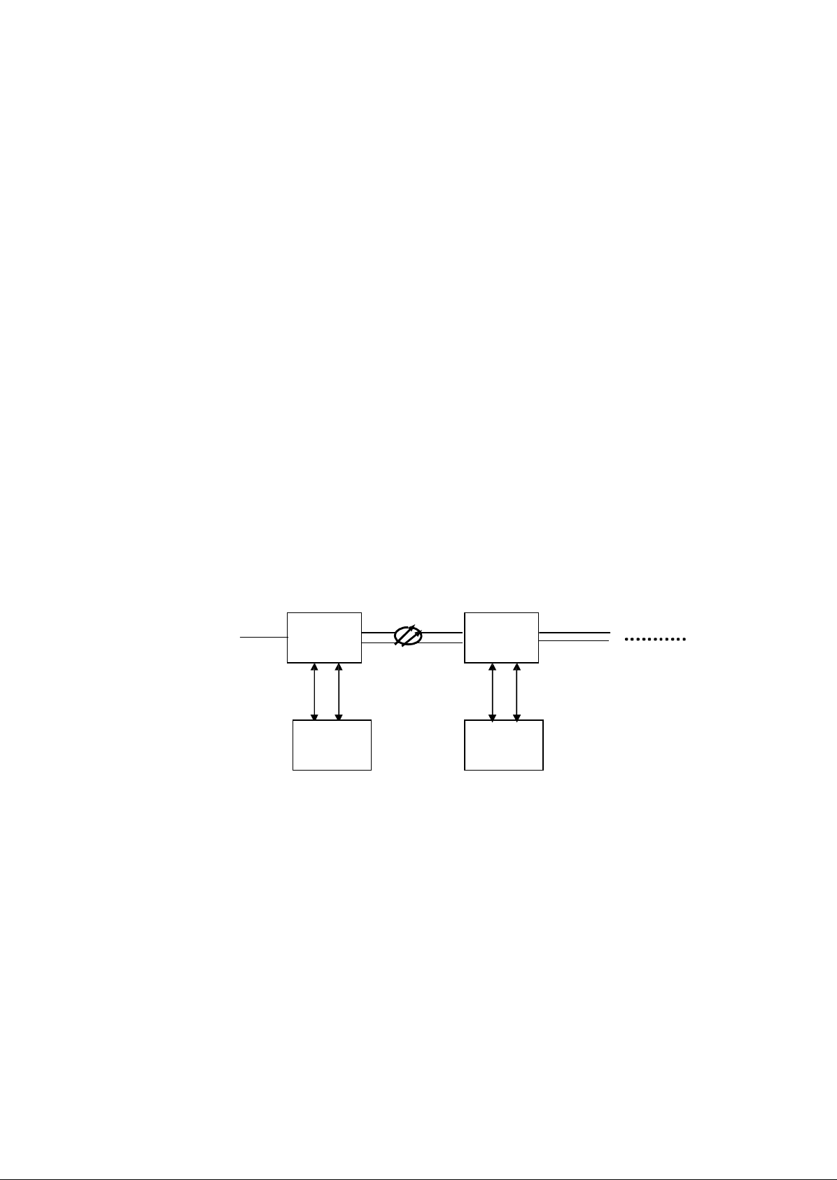
7 Network management system
7.1 Connection mode
Network management message is transmitted through RS-232 serial interface connecting the
computer to the equipment. For remote FMUX 2020, network management message can be
transmitted through the asynchronous data channel of other equipment (such as optical transmission
equipment) or TS31 channel of 2Mb/s primary PCM group. The occupation of TS31 channel should
be set with local-end’s software. Figure 14 shows the networking mode using GK-G04 type
SPDH155 optical transmission equipment. These two FMUX 2020 can share the same monitor
platform. Connection with PC show as figure 14.
RS232
:
GK-G04 GK-G04
RS232 2Mb/s
RS232
2Mb/s
FMUX2020 FMUX2020
7.2 System
installation
Figure 12 FMUX2020 integrated network
management
Operating system: Chinese Window9x/NT.
Computer: IBM PC compatible computer.
Installation of accessory software can reference the following steps:
a) Installing management system software
1) Inserting CD in CD-driver, executing...\install\disk1\
Setup.exe,followingthe
clue,
install
it
at therightlocation(usuallyisdefault).
2)Recording
catalogueinstalled.
b)EstablishS P D Hmanagementinformation data
base(Ne
edn’t
to be
modify
ifitisinstalledas
defaultcatal
ogue
)
1)‘Start’menu,executingBDECFG32.
EX E
in‘FMUXnetworkma
nagementsystem’o
f
‘process’m
enu,then,configuration dialogwindow w
ill
appe a
r.
Page 21

2) Configuring data base language driver process, choosing ‘PARADOX’ data base in ‘Driver Name’ list
frame. Then, single click ‘LANGDRIVE’ in ‘Parameters’, and draw list frame appear at the left side,
choose it’s ‘Borland ENG Latin-1’ language driver process. At this time, you complete the data base
language driver process configuration.
c) Choosing ‘SPDH’ in the main window ‘Aliases Name:’ list, then writing path of SPDH network
management system installation in ‘PATH’ of ‘Parameters’ at right. Such as ‘C:\ SPDH’.
d) Closing (‘x’ at the right-upside) ‘BDE Configuration Utility’, ‘Close configuration File’ dialog frame
appear at this time, and choose ‘YES’ to complete data base configuration.
Operation of SVNMS network management system is introduced in details in HELP file of software.
7.3 Main function and operation introduction
Network management function of FMUX system mainly includes alarm management, configuration
management and performance management.
Alarm information include equipment monitor alarm performance requirement of GB6879 “Technical
Requirements for 2048Kbit/s 30 Channels PCM Multiplexer Equipment”, power supply malfunction, receiving
PCM signal halting (LIS), losing frame address (LFA), error code ratio equal to or exceed 10-3, remote monitoring
alarm (RMA), 64kb/s input signal halting etc. System can display current equipment alarm state and record
historical alarm. State monitor can display real-time signaling state of audio channel, such as hooking on/hooking
off, ringing and so on. As to data interface, state means pass-through and break off state of data.
Configuration means configure composing mode of FMUX2020 via network management
background. Configuration parameter store in E2PROM chip of MCT board, and parameter stored after
FMUX2020 cut off power supply. After hardware resetting, it load configuration as the state before power supply
cut off. Main configuration
management includes:
a) Configuration of board type, configured as the board t ype in practice when appl y
FMUX2020.
b) Time slot configuration, each sub-rate can be configured in anyone of time slot TS1~TS31, and add/drop or
directly communication of branch channel can be configured at double port trunk station.
c) Remote terminal loop-back, remote 2Mb/s, audio and data signal all can be configured as loop-back state to
make testing conveniently.
Network management operation of FMUX system enter in FMUX network management window after finishing
software installation, and its’ detailed use introduction in ‘HELP’ menu. Also you can find detailed use
introduction in network management software CD.
 Loading...