

Page 1

User Manual
Page 2

TV Modulator
Introduction:
TV Modulator is designed to integrate any audio and video signal into TV systems. All A/V sources such as
CCTV, Satellite Receivers, Digital TV, DVD and VCR can be "modulated" to become your TV Channels. You
can distribute CCTV and DVD successfully around the house for every TV. That is the easiest security
solution for household, apartment building, concentrated communities etc...
Diagram:
Installation:
1. Find an empty channel in which there isn’t any A/V signal
2. Connect your video signal to the video in (RCA connector)
3. Connect your audio signal to the audio in R-L(RCA connector)
4. Connect RF out to MODULATOR IN of combiner
5. Combine the original CATV/AIR signal into CATV IN of combiner
6. Connect the TV OUT of combiner to original equipment (ex. CATV system, TV RF-IN)
7. Power on
Composite:
D
VDP
L
A
Y
ER
DVD P
LAY
ER
MICROP HONE
SATELL
I
T
E
CAMEREA
VID
E
OSIG
NAL
AUDIOSIGNAL
Com
biner
C
ATV
/ AIR ANTE NNA
T
VTV...
M
o
dul
atori
n
CATV
inTVo
ut
121110
5. Power Jack
(
DC7.5 ~12V supply
)
6. Power bypass output
( Same with power input )
7. Video Input ( RCA connector )
8. Audio Input L
(
RCA connector )
9. Audio Input R ( RCA connector )
10. RF out ( Connect to combiner )
1. Gain Adjustment
(
RF signal db : ± 0~20db
)
2. Audio Adjustment
3. Video Adjustment
4. LED Channel Display
5. Channel Adjustment
(
Down )
6. Channel Adjustment ( Up )
Page 3
TV System Selection
1. Power on by adaptor, you will know which TV system is on.
2. If it is your system, please switch the button up/down to your favorite channel.
3. If not : (a) Please press the “up” button for few seconds. You will see the LED is
twinkling and then you can start to select your TV system.
(b) After selection, please power off.
(c) Power on again, your system setup is successful.
Lock Channel
After setup, if you want to lock the channel :
(a) Power off.
(b) Press the button “down” persistently then power on.
(c) This channel is locked.
Unlock Channel
After setup, if you want to unlock the channel :
(a) Power off.
(b) Press the button “up” persistently then power on.
(c) You can adjust channels again.
TV System Value : (Multi System switchable - All in one)
1 nC NTSC-M (CATV) CH58(427.25MHZ) --- CH138(877.25MHZ)
2 nA NTSC-M (AIR) CH14(471.25MHZ) --- CH83(885.25MHZ)
3 P1 PAL-B/G E21(471.25MHZ) --- E69(855.25MHZ)
4 P2 PAL-I E21(471.25MHZ) --- E69(855.25MHZ)
5 P3 PAL-D/K E21(471.25MHZ) --- E69(863.25MHZ)
6 P4 PAL-B E21(478.25MHZ) --- E69(814.25MHZ)
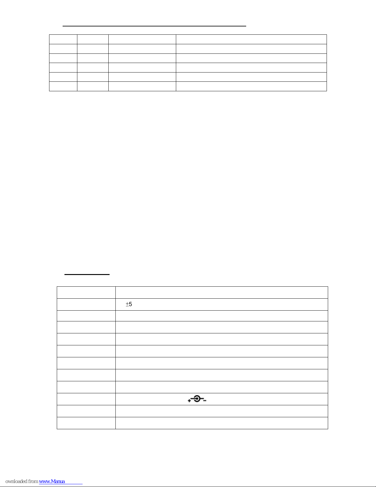
Specification:
Display Mode Digital LED Channel Display.
RF Output Strength
100±5dbuv.
Connector Audio input / video input (RCA connector), RF out (standard "F" female connector)
Video input 1.0Vp-p.for 87.5% modulation.
Audio input Pre-emphasis 75us.
Function Adjustable RF lever, audio deviation, aural carrier ( software ),video modulation adjustable.
Frequency Stability ±5KHZ.
Output Control Range 0 ~ 20 db.
Memory Function Last channel memory.
Power Requirements
DC7.5V - DC12V / 100mA.
Coppact Size 117 x 72 x 32 mm
Modulator Type Double side band modulation
Page 4

4. Remark :
For over channel 100 ( 3 digit display ), it’s showed by a “ dot “ between the 2 digits displayed on the panel.
Example :
58 equals to channel 58.
3.8 equals on the panel 138.
CH58
CH138
 Loading...