

Page 1
1
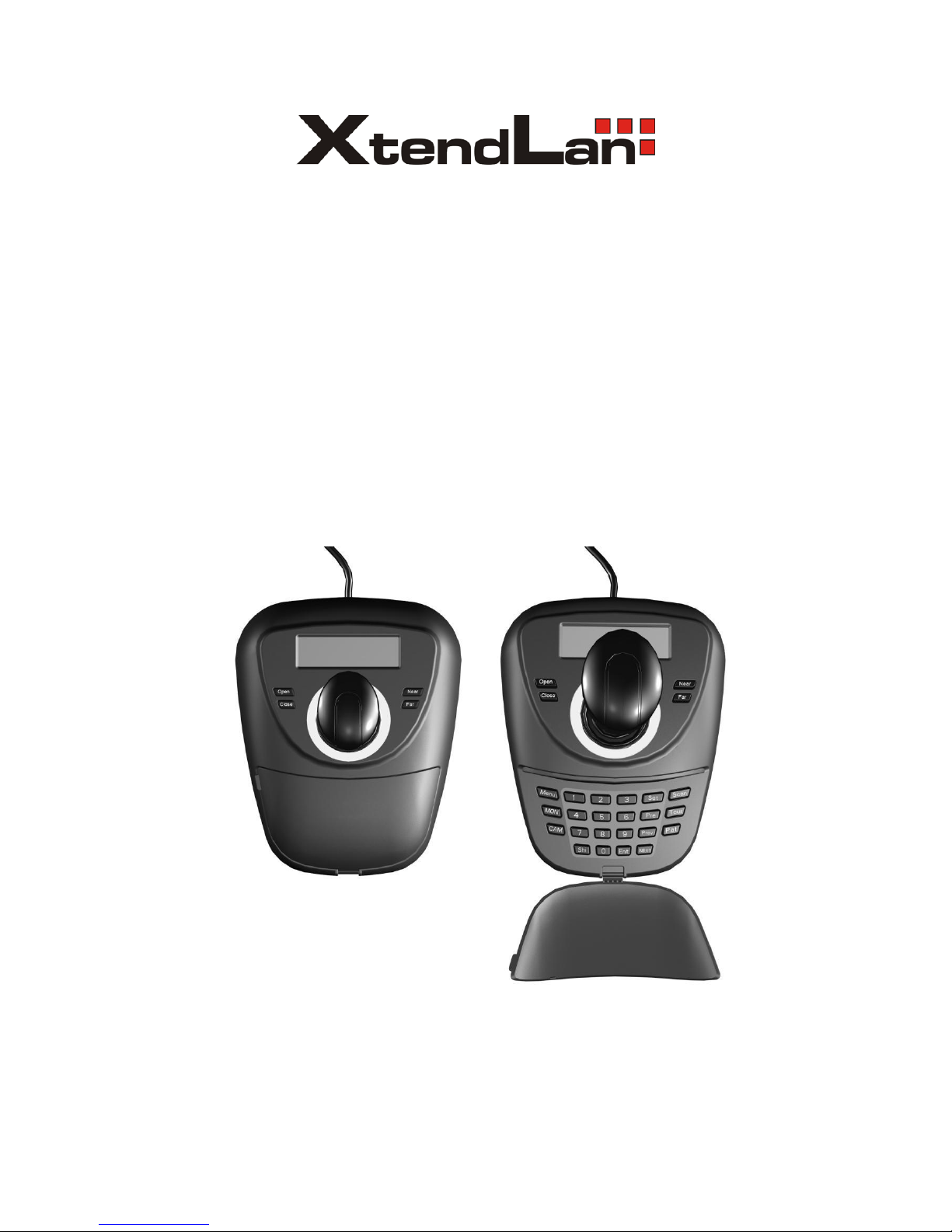
KEYBPTZ3DC
Keyboard Controller
Users' Manual
Page 2

2
Contents
1. Su mmary ---- ----------------- ----------------- ------------------ ----------------- ----------------- ----------------- -------- 3
1.1 Notice ---- ------------------ ------------------ ----------------- ------------------ ----------------- ------------------ -------- 3
1.2 Function & Characteris tic ---------------------------- -------------------------------------------- -----------------------3
1.3 Technical Data --------- ---------------------------- ---------------------------- ---------------------------- ---------------3
2. Keyboard connection ------------------------------------------------------------------------------------------------------- 4
2.1. RS485 interfaces-------------------------------------------------------------------------------------------------------------- 4
2.2 Connect matrix -----------------------------------------------------------------------------------------------------------------4
2.3 Direct connect with Dome--------------------------------------------------------------------------------------------------5
2.4 Key board connection in the Sy stem-----------------------------------------------------------------------------------------5
3. Keyboard operation instruction ------------------- -------------------------------------------------------------6
3.1 Electrify ----------------------------- ---------------------------------------- --------------------------------- 6
3.2 LED d isplay screen ---------------------------------------------------------------------------------------------6
3.3 Joys tick controls do me ------------------------------------------- ------------------------------------------7
3.4 Rigg er the aim dome -----------------------------------------------------------------------------------------7
3.5 Do me lens contro l ---------------------------------------------------------- ------------------------------- 7
3.6 Set do me function------------------------------------ -------------------------------------------------------- 7
3.6.1 Pres et-------------------------------------------- --------------------------------------------------------------- 7
3.6.2 Scan------------------------------------------------------------------------------ -------------------------- 7
3.6.3 Pattern------------------ ---------------------------------------------------------------------------------------- 7
3.6.4 Cru is e----------------------------------------------------------------- ----------------------------------------- 8
3.7 Ca ll do me ma in menu ------------------------------------------------------------------------------------------ 8
3.8 Mat rix Contro l--------------------------------------------------------- ------------------ --------------------8
3.8.1 Switch dome in order---------------------------------------------- -------------------------------------------8
3.8.2 Call matrix main menu ------------------------------------------------------------------------------ ---------8
3.8.3 Confirm after progra m-------------------------------------------- -------------------------------------------8
3.8.4 Change object monitor------------------------------------------ ---------------------------------------------8
4. Key board control---------------------------------------------------------------------------------------------------------------8
4.1 Key board p arameter set up ---------------------------------------------------------------------------------------------------9
4.1.1Key board ID setup -----------------------------------------------------------------------------------------------------------9
4.1.2 Key board baud rate setup -------------------------------------------------------------------------------------------------10
4.1.3 Navigation key adjust ------------------------------------------------------------------------------------------------------10
4.1.4 Disp lay Key board information -------------------------------------------------------------------------------------------11
4.2 Dome setup -------------------------------------------------------------------------------------------------------------------11
4.2.1 Pre-set setup ----------------------------------------------------------------------------------------------------------------11
4.2.2 Dome Scan setup -----------------------------------------------------------------------------------------------------------12
4.2.3 Pattern setup ----------------------------------------------------------------------------------------------------------------12
4.2.4 Tour setup ---------------- --------- --------- --------- --------- ---------- --------- --------- --------- --------- --------- ----13
4.3 Protocol setup ------------------------------------------------------------------------ -------------------------- -------------14
4.4 Exit Key board menu--------------------------------------- ------------------------------------------- ---------------------14
5. App endix ------------------------------------------------------------------------------ ----------------------------------------14
5.1 RS485 Bus general knowled ge--------------------------------------------------------------------------------------------14
5.2 Key board shortcut instruction---------------------------------------------------------------------------------------------16
6. Key board menu index---------------------------------------------------------------------------------------------------------18
Page 3

3
1. Summary
The keyboard is a univers al keyboard of s ecurity monitoring s eries , which can control the ball-type
integrated camera of a ll kinds protocols matrix, which has been equipped with Joys tick which can
control the revolving of the ca mera and the zoo m magnification of lens ; with the LCD s creen and the
function of back-light; which can d is play the current operation order the control protocol name the
current dome ID the current monitor ID and the s t ate of joys ticks . The us er can control the CCT V
s ys tem more eas ily with the joys tick and the LCD s creen.
1.1Notice
Pleas e read the manual care fully and res erve it.
Pleas e advert to the notice in manual.
Pleas e don't place the keyboard in the mois t place.
1.2 Function and Characteristic
●Rs 485 Bus Line, and a keyboard can connect 31 do mes at mos t in the direct control mode.
●can be compatible with all kinds of protocols .
●can control the Iris Focus and Zoom.
●can s et and call the pres et, run the s canning the pattern and the tour。
●can control the matrix and through which can control the dome indirectly.
●equipped with the 3D Joys tick and a LCD s creen
●The LCD can disp lay the current operation order, the control protocol name, the current dome ID ,the
current mon itor ID and the s tate of joysticks .
●Infrared ray emission,emission the same data & content as RS485
1.3 Technical Data
★ Electrical char acter
Input voltage:9V-12V DC
Rating Power:0.5W
★Communicate character
Communicate interface:R S485×1,infr ared emission
Communicate frequency :2400、4800、9600、19200bp s
Communicate distance:RS485 can reach 1.2Km,infr ared emission reaches 10m.
★O perational e nvir onment
Operating te mperature:0℃~50℃
Re lative humid ity les s than 90%
★Phys ical pr operty
L*W*H=168mm*136mm*105 mm
Weight:0.400 kg
Page 4
4
2.Keyboard Connection
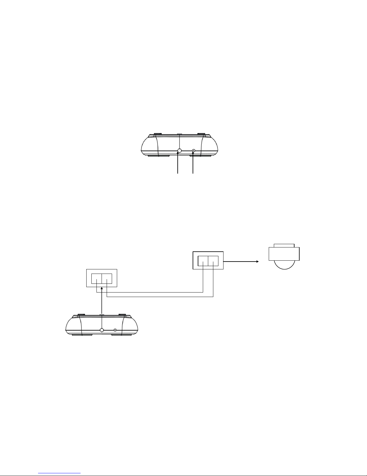
There is interface on the back of the keyboard, wh ich equipped with kinds of co mmunication
Interface RS485 and infra red e mis s ion, which can connect with and control kinds of periphera l
equipments .
2.1. RS485 interfaces
Rs 485 interfaces are on the 2b it ribbon cable connection of the keyboard.RS485 A+ B-) can
connect with the dome when the keyboard controls the dome directly; RS485 A +B-can connect with
DVR o r other keyboards when the keyboard controls the dome by matrix
2. 2 Direct connect with Dome
Power/RS485 IR remote control
Key board connect the Dome wit RS485。The R S485 interface of the Dome is on the commutator of the
Dome.Press the metal button in the han gin g frame,op en the commutator, will find a 4b it p ower jack,follow the
surface instruction to find RS485(A+,B-)follow the instruction。M ay be a different connect way when come from
different manufacturer。
Figure 2-3.1
DC 12V A+ B-
RS485 A+B-
Dome
Keybo ard
Page 5
5
2. 3 Keyboard connection in the system
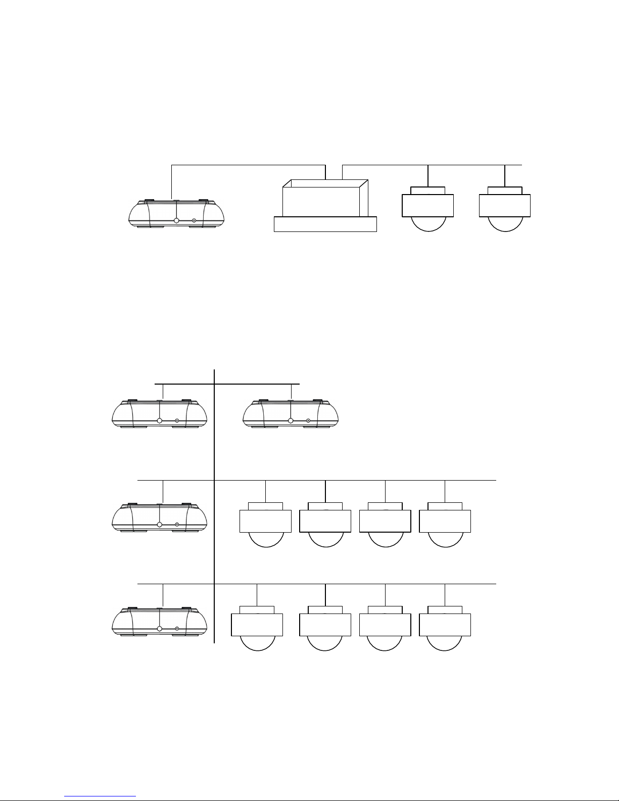
Indirect control the dome when connect with matrix(as figure 2-4.1)。contrariwise will control the domes
directly ,Parallel connect the key board and dome to the bus of RS-485,all the key board can control any dome
amon g them, under this way, the add of the main key board should be “1” and b aud rate should be 9600bp s(as
figur e 2-3.1)
Figure 2 -4.1
matrix
Keybo ard
Dome1 Dome2
Caution
1、the max qu antity of master equip and be charged equip controlled by a RS485 bus is,so when use the
key board to control direct the max dome qu antity is 3
2、max quantity key board in a sy stem is 4,also the 4 key boards should be different ID
Figure 2-4.2
Keybo ard 1 Keybo ard 2
Keybo ard 3
Dome 1 Dome 2 Dome 3 Dome 4
Keybo ard 4
Dome 5 Dome 6 Dome 7 Dome 8
Page 6
6
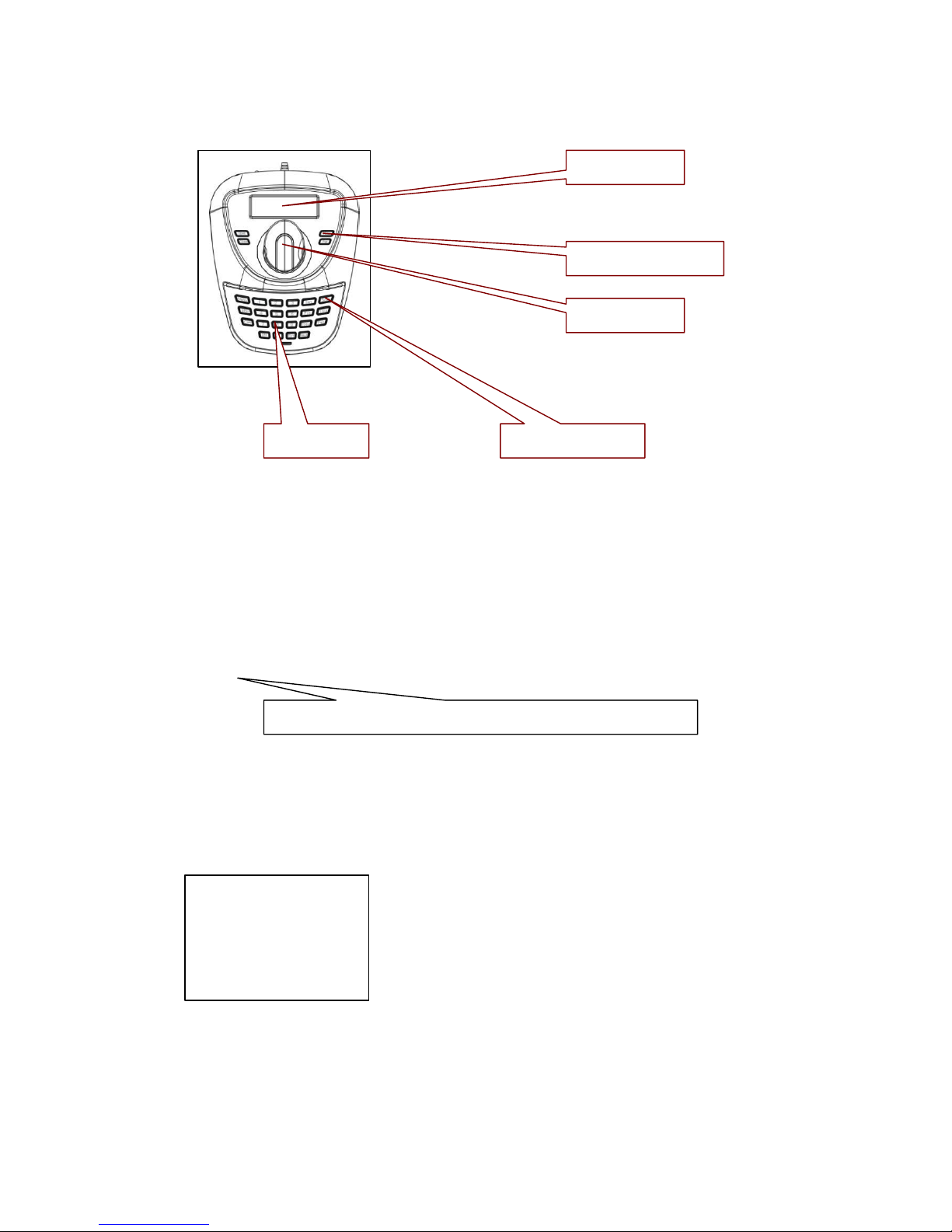
3. Keyboard operation instruction
LCD screen
lens control
3D joystick
Number keys Function keys
Figure 3-1.1
Attention p lease because differ ent sy stem have some diff erent sp ecial op eration way s, so should consider the
actual requir ement when op eration in some sp ecial sy stems
3.1 Electrify
When the p ower is on, the key board will automatically check the baud rate、p rotocol of the key board、aim
dome and the aim monitor, and all the info. will b e disp lay ed on LCD screen.
Attent ion
The joy stick should be nil when key board is initializing
3.2 LCD display screen
LCD screen disp lay contents:aim dome、aim monitor and baud rate etc. And at the end of the content will
show the current operation order and the s tates of joys tick, as follows figure show .When op eration,LCD
back light will on, and will b e off 10s after the op eration。
Camera
Monitor
ID:001
ID:001
Protocol : Pelco-d
Baud rate :
2400bps
Figure 3-1.2
Page 7

7
3. 3 Joystick Controls Dome
Functions of the Joystick: Dome rotation control and Object dome menu setup 。
●When op erate the joy stick at will to any direction Dome will rotate at the same direction ,and the direction will
be disp lay ed below right corner as
When for menu setup , for the upp er menu item, for the next menu;“
”
for the sub menu or
save the setup ; for un-save or exit。
●Direct p rop ortion bet ween the sp eed of the Dome and the lean an gle of the navigation key s,lange lean
angle ,faster rotation sp eed。
3. 4 Rigger the aim dome
【N】+【CAM 】
【N】for Number,inp ut the serial number of the Dome,Press【CAM 】key to amend the add of the aim dome。
3.5 Dome lens control
●Zoom:
Users can control the zoom by rotating the joy stick
●Focus:
Press【FAR 】key focus for far objects。
Press【NEAR】key focus for vicinity objects。
Normally ,Zoom and focus will be ad just ed automaticly by the dome, and with the【FAR 】【NEAR】 to realize the
manual zoom and fo cus
●Iris:
Press【OPEN】key ,manual Iris accr etion,whole white p icture means max ir is
Press【CLOSE】key ,manual Iris minish,whole black p icture means min.iris
3.6 Dome function operation
3.6.1 Pre-set
Pre set:【SET】+【N】 + 【PRESET】
Adjust p re set :【N 】+【PRESET】
【N】for the number of the p re-set。
3.6.2 Scan
Left borderline:【 SET】+【1】+【SCAN】
Right borderline:【 SET】+【2】+【SCAN】
star:【1】+【SCAN】
Enter the menu to set when need change the scan sp eed。
3.6.3 Pattern
Page 8

●design p ath setup :【SET】+【N 】+【PATTERN】+p ath+【SET】+ 0 +【 PATTERN】
Press【SET】key ,inp ut the number of design scan(1-4),p ress【PATTERN】key ,enter the p ath setup state,
when endin g p ress 【SET】key first,then p ress【0】key ,then 【PATTERN】key ,
●starting the design scan:【N】+【PATTERN】inp ut the design scan nu mber(1-4),p ress【PATTERN】key to
starting,
3.6.4 Cruise
starting: 【N】 +【TOUR 】/【TOUR】 cruise number first ,then 【TOUR】key ,starting the cruise。
Direct p ress the 【TOUR】 key when the system only have one cruise .。
3.7 Call Dome main menu
【9】+【5】+【PRESET】:Inp ut 95,p ress【PRESET】key , aim Dome,menu will disp lay on the monitor。
3.8 Matrix control
3.8.1 switch dome orderly
The matrix can conn ect the 16p cs High Sp eed Dome. All the information like the Ser ies NO, Data and time will
disp lay on the monit or while switch the sp eed dome camer a. 【PREV】: switch to p revious camera;Press 【PREV】
2 Sec,it will keep switch till the whole 16 high sp eed dome. Press【Stop 】to stop the switching.【NEXT】:back
forward. Press【NEXT】it will switch to the next camera; Press【NEXT】2 Sec, it will keep back forward switch
till the final 16
th
camera. You can use the 【Stop 】key to stop the op erate
3.8.2 Call matrix main menu
【SHIFT】+【SET】: Call the main menu, the menu will disp lay on the object monitor. How to use the key board
Setting the matrix? Pls ref ers the matrix op erate manu al.
3.8.3 Confirm after progr am
【ENTER】:after the mat rix is p rogra mmed, pres s 【ENTER】, reflects confirm after progra m.
As for the detail progra m, pleas e refer to the matrix operation manual.
3.8.4 Change object monitor
【N】+【M ON】Input the mon itor ID, then pres s MON the image and the menu of the dome that you
controlled by keyboard will d is play in the object monitor
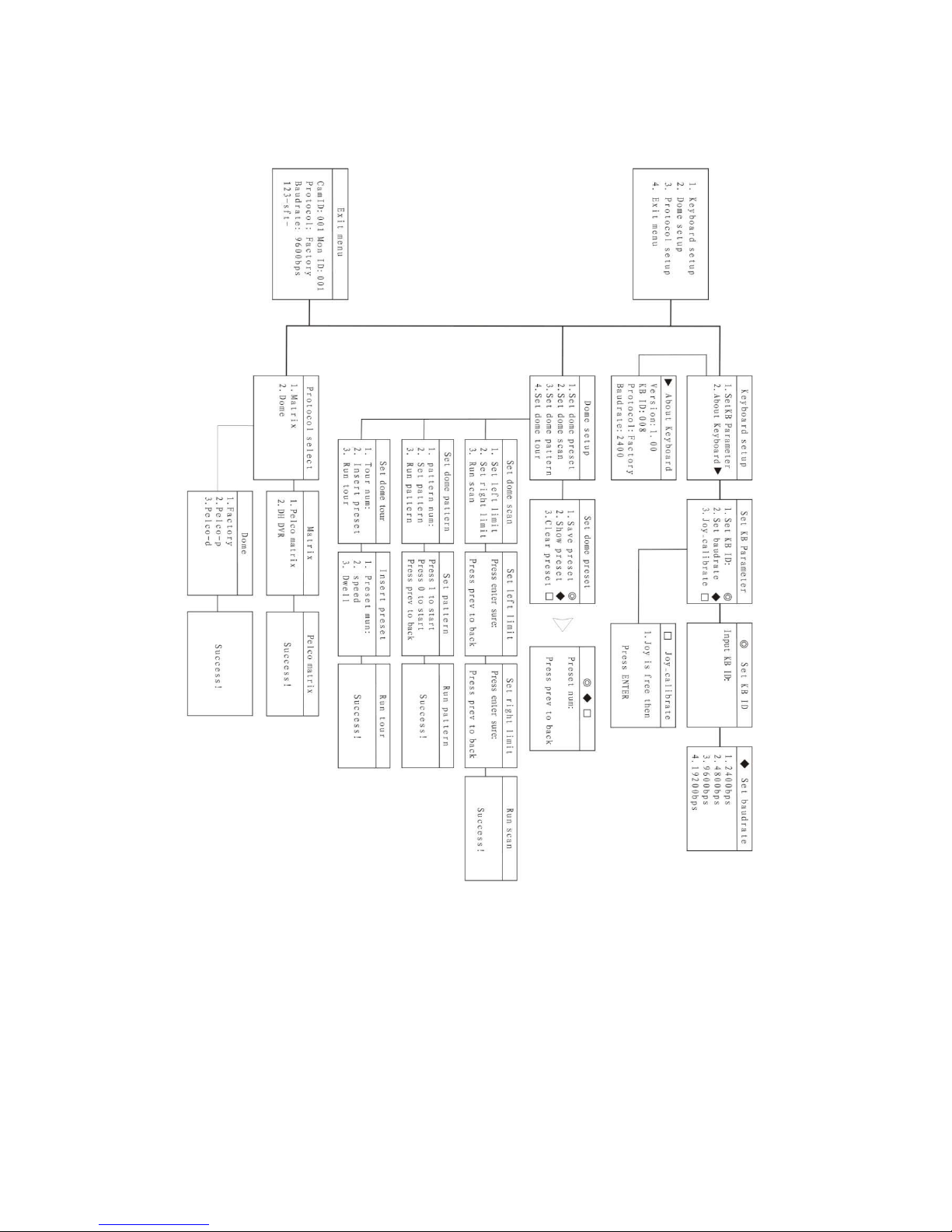
4、Keyboard menu control
●Key board p arameter set up
Turn on the p ower and p ress the【M ENU】, the sy stem information will d isp lay on the screen, like the
p icture(4.1-1), p ress again the system information will disap p ear. You can do all the key board op eration while in
the standby condition or the system information disp lay condition.
Press【M ENU】and hold on 2 sec, y ou will enter the main menu as the p icture (4.1.1-1)show. All the menu
setting need enter the main menu first,and use the corresp ond NO or the Joy calibrate to move UP and DOWN.
While you find the item you need, move the joystick RIGHT or LEFT to enter the menu.
1. Keyboard setup
2. Dome setup
3. Protocol select
8
4. Exit menu
Page 9

9
‘
Picture 4.1-1
● Save the setting
After setting the function y ou need, p ress【ENTER】to save the setting. After finishing the setting, the TFT will
disp lay “Success”.
● Back to Previous menu
Press the【PREV】key to back to the p revious menu.
4.1 Keyboard parameter setting
4.1.1 Keyboard ID set up
1、Enter the main menu
LCD will disp lay (p icture4.1.1-1)
1. Keyboard setup
2. Dome setup
3. Protocol select
4 .Exit menu
Picture4.1.1-1
2、Press【1】to select the key board setting as LCD(Picture4.1.1-2)
1. Set KB ID(1-64):-
2. Set Baudrate:2400bps
3. Joy calibrate
4. About keyboard
Picture 4.1.1-2
3、Press【1】again will show the p icture(Picture4.1.1-3)
1.Set KB ID(1-64):-
Picture4.1.1-3
4、Press【1】to select the ID Setting (Picture4.1.1-4)
1.Set KB ID(1-64):-
Picture 4.1.1-4
Use the ”Number key ” to select the camera ID in the ran ge (1-64);And then p ress the 【Enter】to save, the screen
will disp lay Success as p icture( 4.1.1-5).
Success
Picture4.1.1-5
If the NO y ou inp ut is bey ond the range1 ~64, it will d isp lay Error as p icture(4.1.1-6).
Error
Page 10

10
Picture 4.1.1-6
5、Press 【PREV】or use the shake toward to LEFT to back to p revious menu.
Warning ::
The camera ID def ault is 1. only one key board in a sy stem, it must set to ID as “1”.
Sever al key boards work together at most is 4 key boards, and it must has one key board
ID is ID1, otherwise all the key board can not work. And the LCD will show as p icture
4.1.2 Keyboard Baud Rate Setting
Enter the main menu as the TFT p icture (4.1.1-1) show..
Press【1】will show on the TFT as p icture(4.1.1-2)
Press【2】select the Baud Rate setting, as Picture(4.1.2-1)
2. Set Baud rate: 2400bps (4800bps/9600bps/19200bps)
Picture 4.1.2-1
2400bp s\4800bp s\9600bp s\19200bp s is available(co mmonly under the IR emission mode, baud rate is 2400bps or
4800bp s),You can select the Baud r ate y ou need and p ress the 【ENTER】 to save. If y ou op erate success, the
screen will show“Su ccess”.
Press 【PREV】or move the joy stick to LEFT to back to p revious menu.
Warning:
If connect to the matrix, baud rate must be 9600bps. Several key boards work together, it must use
9600bp s or 19200bps
4.1.3. Joys tick cali brate
When the joys tick at midpoint pos ition ,pls enter the menu to enter the “ joys tick ca lib rate.” Ite m
When calibrating, the joys tick mus t be in a natural s tate. Enter the main menu
LCD will disp lay (p icture4.1.1-1)
2、Press【1】to select the key board setting as LCD(Picture4.1.1-2)
3. 2.Press【3】into joy stick calibr ate as LCD(Picture4.1.3-1)
Joystick is free
then press Enter
Picture4.1.3-1
Press【Enter】and the joystick calibrate is finished as LCD disp lay (Picture4.1.3-2)
Success
Page 11
11
Picture4.1.3-2
Attention: when calibratin g the joy stick, p ls make sure the joystick is in the midp oint p osition
4.1.4 Keyboard information display
Enter the key board information disp lay menu as LCD(Picture 4.1.1-2)
Press【2】to check the key board information as LCD(Picture 4.1.4-1)
4.2 Dome set up
4.2.1 Preset set up
Enter the main menu as p icture (4.1.1-1)and p ress【2】 to enter the dome setting menu as p icture (4.2.1-1);
This p art y ou can set the follow function: Preset, Scan, Pattern, Tour.
1. Set dome preset
2. Set dome scan
3. Set dome pattern
4. Set dome tour
Picture4.2.1-1
Press【1】 enter the dome Preset function setting as p icture (4.2.1-2)
1. Save preset
2. Show preset
3. Clear preset
Picture 4.2.1-2
Item 1 : Sav e p reset ;item 2 : Show the p reset; Item 3: delete the p reset
Press【1】 enter the p reset, y ou can inp ut the p reset NO as p icture(4.2.1-3)show.
Preset num:
(1-128)
Press PREV to back
Picture 4.2.1-3
After enter the p reset menu y ou can use nav igate key control the dome directly, and inp ut the p reset NO to save as
the p icture 4.2.1-4 show. And on the TFT screen will disp lay SUCCESS.
Success!
Press【Prev】back to p revious men.
Warning:
Picture 4.2.1-4
Under commonly mode, Dome can not control by op erate the key s and move the joy sticks ; Wh ile enter the do me
p reset menu, the key board navigate key board can dir ectly control the dome and lens control zone also can control the
dome’s lens.
Page 12

12
Press【2】enter the “Show the p reset ” menu as p icture 4.2.1-5
Preset num:
(1-128)
Press PREV to back
Picture 4.2.1-5
Inp ut the Preset NO that want delete, and p ress the 【ENTER】to call it, and the T FT will disp lay“Success" .
Use the navigate
Key or 【PREV】 back to p revious menu. Press【3】 enter the “clear the Preset ” to clear p reset information as
p icture 4.2.1-6 show.
Preset num:
(1-128)
Press PREV to back
Picture 4.2.1-6
Inp ut the PRESET NO which y ou want to clear, and p ress the Enter to clear it, and it will show “Success"
and back to p revious menu.
4.2.2 Dome Scan set up
Enter the menu(4.1.1-1)
Press【2】 enter the dome setting menu as the p icture(4.2.1-1);
Press【2】again to enter the dome scan setting as p icture 4.2.2-1;
1. Set left lim it
2. Set right lim it
3. Run scan
Picture4.2.1-1
Dome scan setting include the: Left limit, Right Limit and Run scan
Press【1】 to set the Left limit as p icture 4.2.2-2 show.
Press ENTER sure
Press PREV to back
Picture 4.2.2-2
While enter the dome limit setting menu, mov e the dome to the suitable p osition, and p ress【Enter】to save and will
show “Success" and back to p revious menu.
Select the item 2 to set the Right lim it, and do the same as the left limit setting,
Back to the menu and p ress【3】to op erate the Run Scan.
Warning:
Under commonly mode, Dome can not control by op erate the keys and move the joysticks ; While enter
the dome p reset menu, the key board navigate key board can dir ectly control the dome and lens control zone
also can control the dome ’s lens.
Page 13

13
4.2.3 Pattern set up
Enter the menu as the p icture (4.1.1-1)
Press【2】 enter the dome setting menu as the p icture (4.2.1-1);
And then p ress【3】 enter the p attern setting as p icture 4.2.3-1 show
1. Pattern num:
2. Set pattern
3. Run pattern
Picture4.2.3-1
After enter the menu, the sy stem need inp ut the p attern information y ou want, y ou can p ut in the NO1~4 and
Press the 【ENTER】. The mouse will skip to the next item automaticly to set the second p atter y ou need. If y ou
already have it, y ou can skip it and select the 【3】 to run the p attern directly.
Pattern setting:After enter the p attern setting menu, move the do me do the suitable p osition and p ress the
【1】 to start record the scan track. The screen will disp lay “Start
„„,
like the p icture4.2.3-2. Press“0 ” to
finish the scan record, and the screen will show“Su ccess” and back to the p revious menu.
Press 1 to start
Press 0 to start
Press PREV to back
Picture 4.2.3-2
Warning:
Under commonly mode, Dome can not control by op erate the keys and move the joysticks ; While enter
the dome p reset menu, the key board navigate key board can dir ectly control the dome and lens control zone
also can control the dome ’s lens.
4.2.4 Tour set up
Press【2】 enter the dome setting menu, as the p icture 4.2.1-1 show,
And then p ress【4】enter the tour setting as the p icture 4.2.4-1 show.
1. Tour num:
2. Insert preset
3. Run tour
Picture 4.2.4-1
After enter the menu, y ou need inp ut the TOUR information, the range y ou can p ut is 1~6, and p ress the
【ENTER】confirm. Then the mouse will auto skip to the second TOUR setting. If first one is ok, Users can skip it.
And it will show the“Success” and back to the p revious menu.
Select the Item 2 as p icture(4.2.4-2), y ou need inp ut the tour p reset, and in the second item y ou need p ut in
the sp eed information, the ran ge is (1-127); In the third item y ou need inp ut the time how long it need to stop ,
the range is (1-255). After finishin g all the step , p ress the 【ENTER】 and will disp lay “Success”and back to
p revious menu.
1. Preset num:
2. Speed :
3. DWell :
Picture 4.2.4-2
Page 14

14
Press【3】Run the TOUR
Attent ion:
This model have no the insert tour
p reset function
4.3 Protocol set up
Enter the menu as p icture (4.1.1-1), Press 【3】enter the Protocol setting as p icture (4.3-1)
1. Matrix/DVR
2. Dome
Picture 4.3-1
4.3.1 Pelco Matrix model
Press【1】 enter the PELCO M atrix model as the p icture (4.3.1-1);
And then p ress the【ENTER】 to select the Protocol and back to p revious menu.
1. Pelco Matrix
2. DH D VR
Picture 4.3.1-1
4.3.2 Dome control model
Press 【2】enter the dome control model as the p icture ( 4.3.2-1).
Accordin g to the user’s need, select the suitable PROTOCOL and back to the p revious menu.
1.Factory
2.Pelco-P
3.Pelco-D
Picture 4.3.2-1
Enter the menu as p icture (4.1.1-1) and p ress the 【5】to exit the menu.
5. Appendix
5.1 RS 485 Bus Basic Knowledge
●RS 485 Bus Basic Character
Accordin g to RS485 industrial s tandards , RS485 Bus is of half -duple x data trans mis s ion cables
with characteris tic impedance as 120. The ma ximu m load capacity is 32 unit loads (including ma in
controller and controlle r equip ment)
●Distance of RS 485 bus transmission
While use the 0.56 mm (24AWG) twisted cable as the co mmunication, the f arthest distance it can reach as
Page 15
15
follow based on the different Baud rate:
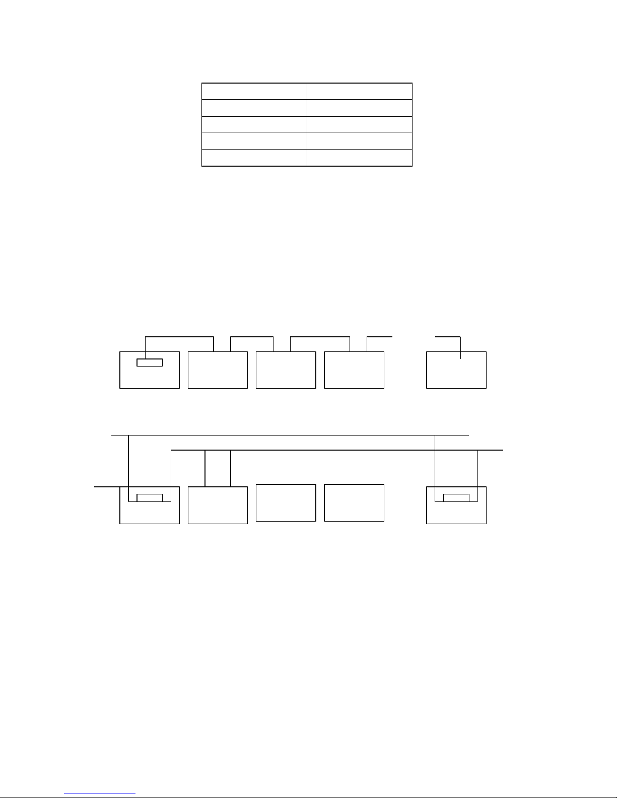
Baud rate
Farthest Distance
2400bp s
1800M
4800bp s
1200M
9600bp s
800M
19200bp s
600M
If us er s elects thinner cables , or ins talls the dome in an environ ment with s trong electromagnetic
interference, or connects lots of equipment to the RS485 Bus , the ma ximu m trans mitting dis tance will
be decreas ed. To increas e the ma ximu m t rans mitt ing dis tance, do the contrary.
● Connecti on and
terminatio
n
resistance
The RS485 standards require a daisy -chain connection between the equip ment. There must be termination
resistance with 120 imp edance at both ends of the connection (refer to p icture 4-1.1).Please refer to p icture 4-1.2
for simp le connection But “ D” should not exceed 7m.
120Ω
………..
1# 2# 3# 4# 32#
Picture 4-1.1
A+
D B-
A+ B-
…………
120Ω
…………
120Ω
1# 2# 3# 4# 32#
Picture 4-1.2
●Pro blems in practical use
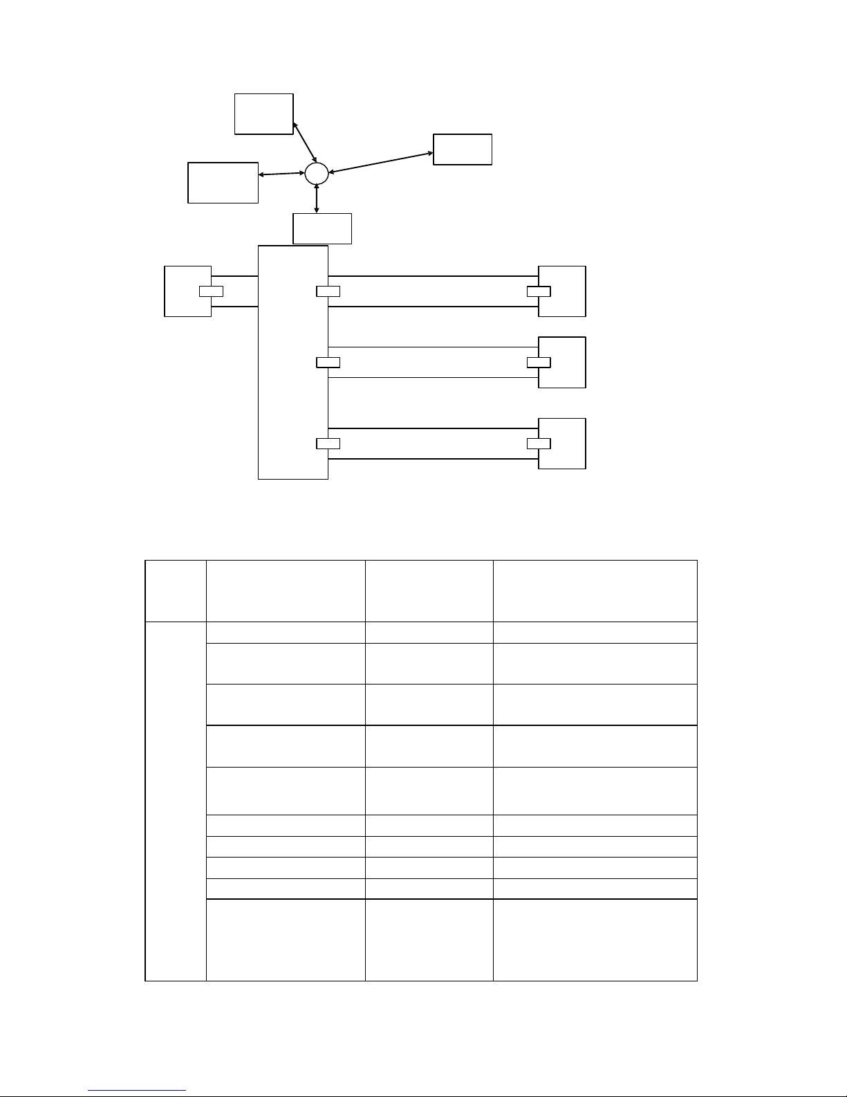
In s ome c ircu ms tances us er adopts a s tar configuration in practical connection. The termination
res is tors mus t be connected to the two equipments that are father away fro m each other, s uch as
equipment1# and 15# (refe r to picture 4-1.3). As the s tar configuration is not in conformity with the
require ments of RS485 s tandards , proble ms s uch as s ignal reflections , lo wer anti -interference
performance aris e when the cables are long in the connection. The reliab ility of control s ignals are
decreas ed with the phenomena that the dome dos e not res ponds to or jus t responds at intervals to the
controller, or dos e continuous operation without stop.
In s uch circums tances the factory will reco mmends the us age of Rs 485 dis tributor. The dis tributor
can change the star configuration connection to the mode of connection s tipulated in the
RS485s tand ards . The new connection achieves reliable data trans mis s ion (refer to picture 4 -1.4)
Page 16
16
120Ω
1#
32#
6#
M ain Controller
120Ω
15 #
Picture 4-1.3
A+
120Ω
1#
B-
120Ω
2#
.
.
.
120Ω
3#
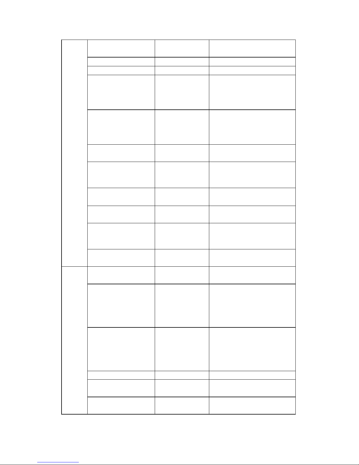
5.2 Keyboard shortcut o peration manual
Picture 4-1.4
Working
Mode
shortcut
Operation object
Function
Direct
Control
Mode
Press【SET】for 2 seconds
Keybo ard
IR remote ON/OFF
Press 【MENU】for 2
seconds
Keybo ard
Enter the system setting
【N】+【CAM】
High speed dome
Input Dome ID, press 【CAM】to
select object dome.
【Rotate the joystick
anti-clockw ise】
High speed dome
Zoom in
【Rotate the joystick
clockw ise】
High speed dome
Zoom out
【FAR】
High speed dome
Press【FAR】, far focus
【NEAR】
High speed dome
Press【NEAR】, near focus
【CLOSE】
High speed dome
Press【CLOSE】, reduce iris
【OPEN】
High speed dome
Press【OPEN】, increase Iris
【SET】+【N】+
【PRESET】
High speed dome
Ad just the image to object
position, Press【SET】to input the
preset, and press【PRESET】to set
the preset
Page 17
17
【N】+ 【PRESET】
High speed dome
Input preset ID, press【Preset】to
call the preset
【SHI】+【1】+【ENT】
High speed dome
ON/OFF w ater Wiper
【SHI】+【2】+【ENT】
High speed dome
ON/OFF auxiliary light
【SET】+【1】+【SCAN】
High speed dome
Ad just the image to object
position, press Set to input
【1】,then press Scan to se【t scan】
left lim it.
【SET】+【2】+【SCAN】
High speed dome
Ad just the image to object
position, press Set to input【2】,
then press【Scan】to set scan right
lim it.
【1】+【SCAN】
High speed dome
Input 【1】, press 【Scan】 to run
scan.
【SET】+【N】+
【PATTERN】
High speed dome
Press 【 Set 】 to input pattern
number, press【Pattern】 to record
pattern path.
【SET】+【0】+
【PATTERN】
High speed dome
Press【SET】 and input0, Press
【PATTERN】to save path
【N】+【PATTERN】
High speed dome
Input the pattern path(1-4),Press
【PATTERN】to start pattern
【N】+ 【TOUR】/
【TOUR】
High speed dome
Input the TOUR NO, press
【 TOUR 】 or directly press
【TOUR】to start the Tour
【9】+【5】+【PRESET】
High speed dome
Input 95 and press【Preset】to call
the menu
PELCO
Matrix
Mode
【SHIFT】+ 【SET】
Matrix
Press【SHIFT】and 【SET】to call
the matrix menu
【PREV】
Matrix
Press 【 PREV 】 skip to the
previous dome, hold on 2sec on
【PREV】to continuously skip the
sixteen domes of connection
matrix forw ards
【NEXT】
Matrix
Press 【 NEXT 】 skip to the
previous dome, hold on 2sec on
【NEXT】to continuously skip the
sixteen domes of connection
matrix backw ards
【Stop】
Matrix
Stop sw itch
【ENTER】
Matrix
After program, press【Enter】to
confirm.。
【N】+ 【MON】
Matrix
Input monitor ID, press【Cam】 to
select object monitor
Page 18
18
 Loading...