

Page 1

1
DVRL22-1670J
22-inch Combo Digital Video Recorder
User’s Manual
Page 2

2
Table of Contents
1 FEATURES AND SPECIFICATIONS ................................................................ 10
1.1 Overview ............................................................................................................................................... 10
1.2 Features ................................................................................................................................................ 10
1.3 Specifications ....................................................................................................................................... 11
2 OVERVIEW AND CONTROLS ......................................................................... 15
2.1 Front Panel, Side Panel and Rear Panel ......................................................................................... 15
2.2 Connection Sample ............................................................................................................................. 16
2.3 Remote Control .................................................................................................................................... 16
2.4 Mouse Control ...................................................................................................................................... 18
3 INSTALLATION AND CONNECTIONS ............................................................. 20
3.1 Check Unpacked Device .................................................................................................................... 20
3.2 About Front Panel and Real Panel ................................................................................................... 20
3.3 Device Installation ............................................................................................................................... 20
3.4 HDD Installation ................................................................................................................................... 20
3.5 Connecting Power Supply .................................................................................................................. 21
Page 3

3
3.6 Connecting Video Input and Output Devices .................................................................................. 22
3.6.1 Connecting Video Input .................................................................................................................. 22
3.6.2 Connecting Video Output ............................................................................................................... 22
3.7 Connecting Audio Input & Output, Bidirectional Audio .................................................................. 23
3.7.1 Audio Input ....................................................................................................................................... 23
3.7.2 Audio Output .................................................................................................................................... 23
3.8 Alarm Input and Output Connection ................................................................................................. 24
3.8.1 Alarm Input and Output Details ..................................................................................................... 25
3.8.2 Alarm Input Port .............................................................................................................................. 25
3.8.3 Alarm Output Port ........................................................................................................................... 26
3.9 RS232.................................................................................................................................................... 26
3.10 RS485.................................................................................................................................................... 27
3.11 Other Interfaces ................................................................................................................................... 27
4 OVERVIEW OF NAVIGATION AND CONTROLS ............................................ 29
4.1 Login, Logout & Main Menu ............................................................................................................... 29
4.1.1 Login ................................................................................................................................................. 29
4.1.2 Main Menu ....................................................................................................................................... 29
4.1.3 Shutdown ......................................................................................................................................... 30
4.1.4 Auto Resume after Power Failure ................................................................................................ 30
4.1.5 Replace Button Battery .................................................................................................................. 30
4.2 Manual Record ..................................................................................................................................... 31
4.2.1 Live Viewing ..................................................................................................................................... 31
4.2.2 Manual record.................................................................................................................................. 31
4.3 Search & Playback .............................................................................................................................. 33
4.4 Schedule ............................................................................................................................................... 35
4.4.1 Schedule Menu .................................................................................................................................... 35
4.4.2 Snapshot .......................................................................................................................................... 36
Page 4

4
4.4.3 Image FTP ....................................................................................................................................... 38
4.5 Detect .................................................................................................................................................... 38
4.5.1 Go to Detect Menu ............................................................................................................................... 38
4.5.2 Motion Detect ........................................................................................................................................ 38
4.5.3 Video Loss............................................................................................................................................. 41
4.5.4 Camera Masking .................................................................................................................................. 41
4.6 Alarm Setup and Alarm Activation .................................................................................................... 42
4.6.1 Go to alarm setup interface ........................................................................................................... 42
4.6.2 Alarm setup ...................................................................................................................................... 42
4.7 Backup .................................................................................................................................................. 44
4.7.1 Detect Device ....................................................................................................................................... 44
4.7.1 Backup .............................................................................................................................................. 45
4.8 PTZ Control and Color Setup ............................................................................................................ 46
4.8.1 Cable Connection ................................................................................................................................ 46
4.8.2 PTZ Setup ............................................................................................................................................. 46
4.8.3 3D Intelligent Positioning Key ............................................................................................................ 47
4.9 Preset/ Patrol/Pattern/Scan................................................................................................................ 48
4.9.1Preset Setup ......................................................................................................................................... 49
4.9.2 Activate Preset ..................................................................................................................................... 49
4.9.3 Patrol setup (Tour Setup) ................................................................................................................... 49
4.9.4 Activate Patrol (tour) ........................................................................................................................... 49
4.9.5 Pattern Setup ....................................................................................................................................... 49
4.9.6 Activate Pattern Function ................................................................................................................... 50
4.9.7 Auto Scan Setup ................................................................................................................................. 50
4.9.8 Activate Auto Scan .............................................................................................................................. 50
4.10 Flip ......................................................................................................................................................... 50
5 UNDERSTANDING OF MENU OPERATIONS AND CONTROLS ................... 52
5.1 Menu Tree ............................................................................................................................................ 52
5.2 Main Menu ............................................................................................................................................ 52
Page 5

5
5.3 Setting ................................................................................................................................................... 53
5.3.1 General ............................................................................................................................................. 53
5.3.2 Encode ............................................................................................................................................. 55
5.3.3 Schedule .......................................................................................................................................... 56
5.3.4 RS232 ............................................................................................................................................... 56
5.3.5 Network ............................................................................................................................................ 57
5.3.6 Alarm................................................................................................................................................. 64
5.3.7 Detect ............................................................................................................................................... 64
5.3.8 Pan/Tilt/Zoom .................................................................................................................................. 64
5.3.9 Display .............................................................................................................................................. 65
5.3.10 Default .......................................................................................................................................... 66
5.4 Search ................................................................................................................................................... 67
5.5 Advanced .............................................................................................................................................. 67
5.5.1 HDD Management .......................................................................................................................... 67
5.5.2 Abnormity ......................................................................................................................................... 68
5.5.3 Alarm Output.................................................................................................................................... 69
5.5.4 Manual Record ................................................................................................................................ 69
5.5.5 Account ............................................................................................................................................. 69
5.5.6 Auto Maintain ................................................................................................................................... 72
5.5.7 TV Adjust .......................................................................................................................................... 72
5.6 Information ............................................................................................................................................ 72
5.6.1 HDD Information ............................................................................................................................. 73
5.6.2 BPS ................................................................................................................................................... 74
5.6.3 Log .................................................................................................................................................... 74
5.6.4 Version ............................................................................................................................................. 74
5.6.5 Online Users .................................................................................................................................... 75
5.7 Shutdown .............................................................................................................................................. 75
6 ABOUT AUXILIARY MENU .............................................................................. 77
6.1 Go to Pan/Tilt/Zoom Menu ................................................................................................................. 77
6.1.1 3D Intelligent Positioning Key ....................................................................................................... 77
6.2 Preset /Patrol / Pattern /Border Function ....................................................................................... 78
6.2.1 Preset Setup .................................................................................................................................... 79
Page 6

6
6.2.2 Activate Preset ................................................................................................................................ 79
6.2.3 Patrol Setup ..................................................................................................................................... 79
6.2.4 Activate Patrol ................................................................................................................................. 79
6.2.5 Pattern Setup ................................................................................................................................... 79
6.2.6 Activate Pattern Function ............................................................................................................... 80
6.2.7 Border Setup.................................................................................................................................... 80
6.2.8 Activate Border Function ............................................................................................................... 80
6.2.9 Flip..................................................................................................................................................... 80
7 WEB OPERATION ............................................................................................ 81
7.1 Network Connection ............................................................................................................................ 81
7.2 Login ...................................................................................................................................................... 81
7.2.1 Real-time Monitor ............................................................................................................................ 83
7.2.2 PTZ ................................................................................................................................................... 85
7.2.3 Color ................................................................................................................................................. 88
7.2.4 Picture Path and Record Path ...................................................................................................... 88
7.3 Configure .............................................................................................................................................. 89
7.3.1 System Information ......................................................................................................................... 89
7.3.2 System Configuration ..................................................................................................................... 91
7.3.3 Advanced ....................................................................................................................................... 109
7.3.4 Additional Function ....................................................................................................................... 115
7.4 Search ................................................................................................................................................. 116
7.5 Alarm ................................................................................................................................................... 119
7.6 About ................................................................................................................................................... 120
7.7 Log out ................................................................................................................................................ 120
7.8 Un-install Web Control ...................................................................................................................... 121
8 PROFESSIONAL SURVEILLANCE SYSTEM ................................................ 122
Page 7

7
9 FAQ ................................................................................................................. 123
APPENDIX A HDD CAPACITY CALCULATION ................................................. 128
APPENDIX B COMPATIBLE USB DRIVE LIST .................................................. 129
APPENDIX C COMPATIBLE CD/DVD BURNER LIST ........................................ 130
APPENDIX D COMPATIBLE SATA HDD LIST ................................................... 131
APPENDIX E EARTHING .................................................................................... 133
APPENDIX F TOXIC OR HAZARDOUS MATERIALS OR ELEMENTS ................ 138
Page 8

8
Welcome
Thank you for purchasing our 22-inch combo DVR!
This user’s manual is designed to be a reference tool for the installation and operation of your
system.
Here you can find information about this series 22-inch combo DVR features and functions, as
well as a detailed menu tree.
Before installation and operation please read the following safeguards and warnings carefully!
Page 9

9
Important Safeguards and Warnings
1.Electrical safety
All installation and operation here should conform to your local electrical safety codes.
We assume no liability or responsibility for all the fires or electrical shock caused by improper
handling or installation.
2.Transportation security
Heavy stress, violent vibration or water splash are not allowed during transportation, storage and
installation.
3.Installation
Keep upwards. Handle with care.
Do not apply power to the 22-inch combo DVR before completing installation.
Do not place objects on the 22-inch combo DVR
4.Qualified engineers needed
All the examination and repair work should be done by the qualified service engineers.
We are not liable for any problems caused by unauthorized modifications or attempted repair.
5.Environment
This series product working temperature ranges from 0℃ to 40℃.
The 22-inch combo DVR should be installed in a cool, dry place away from direct sunlight,
inflammable, explosive substances and etc.
Please unplug the power cable in case there is strong wind or lightning.
6. Accessories
Be sure to use all the accessories recommended by manufacturer.
Before installation, please open the package and check all the components are included.
Contact your local retailer ASAP if something is broken in your package.
7. About the LCD
During the installation, do not push or squeeze the LCD or its rim; it may result in LCD damage.
During the operation or storage, please avoid the hard object to scuff the screen.
Please keep the LCD clean. Use the soft cloth to clean regularly. Do not use gasoline, alcohol or
other chemical reagent to clean the screen.
Do not allow the LCD video standstill for a long time; it may result in permanent damage.
7. Lithium battery
Improper battery use may result in fire, explosion, or personal injury!
When replace the battery, please make sure you are using the same model!
Page 10

10
1 FEATURES AND SPECIFICATIONS
1.1 Overview
This series 22-inch combo DVR integrates the DVR (Digital Video Recorder) and displayer
together. It is an excellent digital monitor product of decent appearance, strong function and
reliable performance.
It adopts embedded Linux OS to maintain stable operation. Popular H.264 video compression
algorithm and G.711 audio compression technology realize high quality, low bit stream. Unique
frame by frame play function is suitable for detailed analysis. It has various functions such as
record, playback, monitor at the same time and can guarantee audio and video synchronization.
This series product has advanced technology and strong network data transmission function.
It can work in the local end, and at the same time, when connecting it to the professional
surveillance software (PSS), it can connect to security network to realize strong network and
remote monitor function.
This series 22-inch combo DVR integrates the high quality LCD of vivid image and long-duration.
Special and popular 22-inch width screen is suitable for remote video monitor and local display. It
is a product of dual functions, of modern and character tastes. This series product can be widely
used in various areas such as super market, chain store, home use client, transportation,
intelligent residential district and etc. It is an ideal option for the future home use security product.
1.2 Features
This series product has the following features:
Real-time monitor
The LCD displays the real-time monitor video. Support BNC and HDMI video output.
Support BNC video input, support PC port (VGA port) connection. It can be used as a displayer.
LCD Control Function
Press the power button in the front panel for a long time to boot up or shut down the device.
Press the power button in the front panel for a short time to open/close the LCD.
Support LCD standby setup function.
Mouse, front panel and remote control can awake the LCD.
The M button can control the switch of the PC input signal and the monitor video of the main
board.
Storage function
Special data format to guarantee data security and can avoid vicious data modification.
Compression format
Support multiple-channel audio and video signal. An independent hardware decodes the audio
and video signal from each channel to maintain video and audio synchronization.
Page 11

11
Parameter
16-channel
8-channel
4-channel
System
Main
Processor
High-performance industrial embedded micro controller
OS
Embedded LINUX
System
Resources
Multiplex operations: Multiple-channel record, multiple-channel playback
and network operation simultaneously
Interface
User-friendly graphical user interface
Input
Devices
Front /side panel, USB mouse, remote control
Input
Method
Arabic number, English character, donation and extension Chinese
(optional)
Shortcut
Function
Copy/paste operation, USB mouse right-key shortcut menu, double click
USB mouse to switch screen.
Backup function
Support backup operation via USB port (such as flash disk, portable HDD, burner)
Client-end user can download the file to local HDD to backup via network.
Record playback function
Support each channel real-time record independently, and at the same time it can support search,
forward play, network monitor, record search, download and etc.
Support various playback modes: slow play, fast play, backward play and frame by frame play.
Support time title overlay so that you can view event accurately occurred time
Support specified zone enlargement.
Network operation
Support network remote real-time monitor, remote record search and remote PTZ control.
Alarm activation function
Multiple-channel alarm outputs (on-off) to realize alarm activation and on-site light control.
The alarm input port and output port has the protection circuit to guarantee device safety.
Communication port
RS485 port can realize alarm input and PTZ control.
RS232 port can connect to keyboard to realize central control, and can also connect to PC COM
to upgrade system and realize maintenance, and matrix control.
Standard Ethernet port can realize network access function.
PTZ control
Support PTZ decoder via RS485.
Support various decode protocols to allow the PTZ to control the speed dome.
Intelligent operation
Mouse operation function
In the menu, support copy and paste setup function
Slight function differences may be found due to different series.
1.3 Specifications
Page 12

12
Compression
Standard
Video
Compressio
n
H.264
Audio
Compressio
n
G.711A
Video monitor
Video Input
1-channel PC input.
16-ch composite video
input: (NTSC/PAL)
BNC (1.0VB
P- P,
B75Ω)
1-channel PC input.
8-ch composite video
input: (NTSC/PAL)
BNC (1.0VB
P- P,
B75Ω)
1-channel PC input.
4-ch composite video
input: (NTSC/PAL)
BNC (1.0VB
P- P,
B75Ω)
Video
Output
1-ch PAL/NTSC, BNC (1.0VP- P, 75Ω) composite video signal output.
1-ch HDMI output
Support TV/HDMI video output at the same time.
Video
Standard
PAL (625 TV line, 50f/s), NTSC (525 TV line, 60f/s)
Record
Speed
Real-time Mode: PAL 1f/s to 25f/s per channel and NTSC 1f/s to 30f/s
per channel
Video
Partition
1/4/8/9/16 windows
1/4/8/9 windows
1/4 windows
Monitor
Touring
Support monitor tour functions such as alarm, motion detection, and
schedule auto control.
Resolution
(PAL/NTSC
)
PAL(625 TV line,50f/s)/NTSC(525 TV line,60f/s)
Real-time monitor:
D1 704×576(PAL)/704×480(NTSC)
Playback 1/16 (take the 16-channel series for example):
D1 704×576/704×480(6f/s. When other channels are CIF, the 1st and 9th
channel can set 25f/s.) , CIF 352×288/ 352×240, QCIF
176×144/176×120.
Please refer to the Encode chapter for detailed information.
Support dual streams: extra stream resolution QCIF 176×144/176×120
Image
Quality
6-level image quality (Adjustable)
Privacy
mask
Support one privacy mask of user-defined size in full screen.
Support max 4 zones.
Image
Information
Channel information, time information and privacy mask zone.
TV Adjust
Adjust TV output zone suitable to anamorphic video.
Channel
Lock
Cover secret channel with blue screen though system is encoding
normally.
Screen-lock function to prevent unauthorized user seeing secret video.
Channel
Information
Channel name, recording status, screen lock status, video loss status
and motion detection status are shown on the bottom left of display
screen.
Color
Configuratio
n
Hue, brightness, contrast, saturation and gain setup for each channel.
Audio
Audio Input
4-ch 200-2000mv 10KΩ(BNC)
Audio
Output
1-ch audio output 200-3000mv 5KΩ(BNC)
Bidirectional
Audio
1-channel bidirectional talk input 200-3000mv 10KΩ(BNC)
1-channel bidirectional talk output 200-3000mv 5KΩ (BNC) (The
bidirectional talk input reuses the first audio input channel.)
Hard Disk
1 built-in SATA port. Support 1 one HDD.
Page 13

13
Hard disk
Hard Disk
Occupation
Audio:G711A , 28.125MMByte/h
Video:56-900MByte/h
Record and
playback
Recording
Mode
Manual recording, motion detection recording, schedule recording and
alarm recording
Priority: Manual recording> alarm recording>motion detection
recording>schedule recording.
Recording
Length
1 to 120 minutes single record duration (Default setup is 60 minutes)
Playback
Repeat
Way
When hard disk is full, system can overwrite previous video file.
Record
Search
Various search engines such as time, type and channel.
Playback
Mode
Various fast play, slow play speeds, manual frame by frame playback
and reverse play mode.
Various File
Switch
Ways
Can switch to previous or next file or any file in current play list.
Can switch to file on other channel of the same time. (If there is a file)
Support file continuous play, when file is end system auto plays the next
file in the current channel
Multichannel
Playback
Support 1/4/9/16-channel playback.(The playback window may varu due
to different series.)
Window
Zoom
Switch between self-adaptive screen/full screen when playback
Partial
Enlargemen
t
When in one-window full-screen playback mode, you can select any zone
to activate partial enlargement function.
Backup
function
Backup
Mode
Support peripheral USB backup device. (Flash disk, portable disk, USB
burner and etc.)
Support network download and backup
Network
Function
Network
control
View monitor channel remotely.
Device configuration access and setup through client-end and web
browser
Upgrade via client–end or browser to realize remote maintenance.
View alarm information such as external alarm, motion detection and
video loss via client.
Support network PTZ lens control
File download backup and playback
Multiple devices share information via corresponding software.
Duplex transparent COM.
Network alarm input and output
Bidirectional audio.
Motion
Detection and
Alarm
Motion
Detection
Zone setup: support 396(PAL 22×18 ) /330(NTSC 22×15) detection
zones.
Various sensitivity levels.
Alarm can activate record or external alarm or screen message prompt.
Video Loss
Alarm can activate external alarm or screen message prompt.
External
Alarm
Support record activation function or activate external alarm or screen
message in specified period.
Manual
Alarm
Control
Enable or disable alarm input channel
Support analog alarm signal to specific alarm output channel.
Alarm Input
8-ch alarm input(You can set normal open or normal close type to
select the alarm type. )
Alarm
Output
3-channel relay output.
Page 14

14
Alarm Relay
30V DC/ 2A,125V AC/ 1A(activation alarm )
Interface
USB
Interface
2 USB 2.0 ports.
Network
connection
RJ45 10M/100M self-adaptable Ethernet port
RS485
PTZ control port
Support various PTZ control protocols.
RS232
Ordinary COM (Debug),keyboard connection and transparent serial
port(COM input and output via network )
System
Information
Hard Disk
Information
Display HDD current status
Data
Stream
Statistics
Data stream statistics for each channel (in wave mode)
Log
statistics
Backup to 1024 log files.
Support various search engines such as time and type.
Version
Display version information: channel amount, alarm input and output
amount, system version and release date.
On-line user
Display current on-line user
User
Management
User
Manageme
nt
Multi-lever user management; various management modes
Integrated management for local, COM and network user.
Configurable user power.
Support user /group and its corresponding rights modification.
No limit to the user or group amount.
Password
Authenticati
on
Password modification
Administrator can modify other user’s password.
Account lock strategy
Five times login failure in thirty minutes may result in account lock.
Upgrade
Web, client-end and update tool.
Login, Logout and Shutdown
Password login protection to guarantee safety
User-friendly interface when login. Provide the following options: Logout
/shutdown/ restart.
Right authentication when shut down to make sure only those proper
people can turn off 22-inch combo DVR.
LCD
Spec
LCD dimensions: 21.5-inch (16.9)
Color restoration capability:16.7M standard
Horizontal (90*89), tilt (90*85).
Responding time: TR=1.3ms,TF=3.7ms
Tub life span: 50000 hours
General
Parameter
Power
DC +19V
Power
Consumptio
n
≤45W (With adapter and HDD)
Working
Temperatur
e
0℃-+55℃
Working
Humidity
10%-90%
Air
Pressure
86kpa-106kpa
Dimension
546mm(W)x60mm(T)x360mm(H. without the bracket)
546mm(W)x185mm(T)x407.6mm(H. With the bracket)
Weight
5.8 Kg (Exclude HDD)
Installation
Mode
Desktop/wall-mount installation
Page 15

15
SN
Function
1
M button
2
Power button
3
USB port
4
Power indication light
5
Remote control receiver to receive the signal from the remote control.
SN
Function
1
Power button
2
Power socket
3
Alarm input, alarm output, RS485 port.
4 5
2 Overview and Controls
This section provides information about front panel and rear panel. When you install this series
22-inch combo DVR for the first time, please refer to this part first.
2.1 Front Panel, Side Panel and Rear Panel
The front pane and side panel is shown as in Figure 2-1.
Figure 2-1
Please refer to the following sheet for detailed information.
The rear panel is shown as below. See Figure 2-2.
Figure 2-2
Please refer to the following sheet for rear panel information.
Page 16

16
4
Network port
5
USB port
6
RS-232 port
7
HDMI port
8
PC input
9
Video CVBS input, audio CVBS input,
Video CVBS output, audio CVBS output.
When connect the Ethernet port, please use crossover cable to connect the PC and use the
straight cable to connect to the switcher or router.
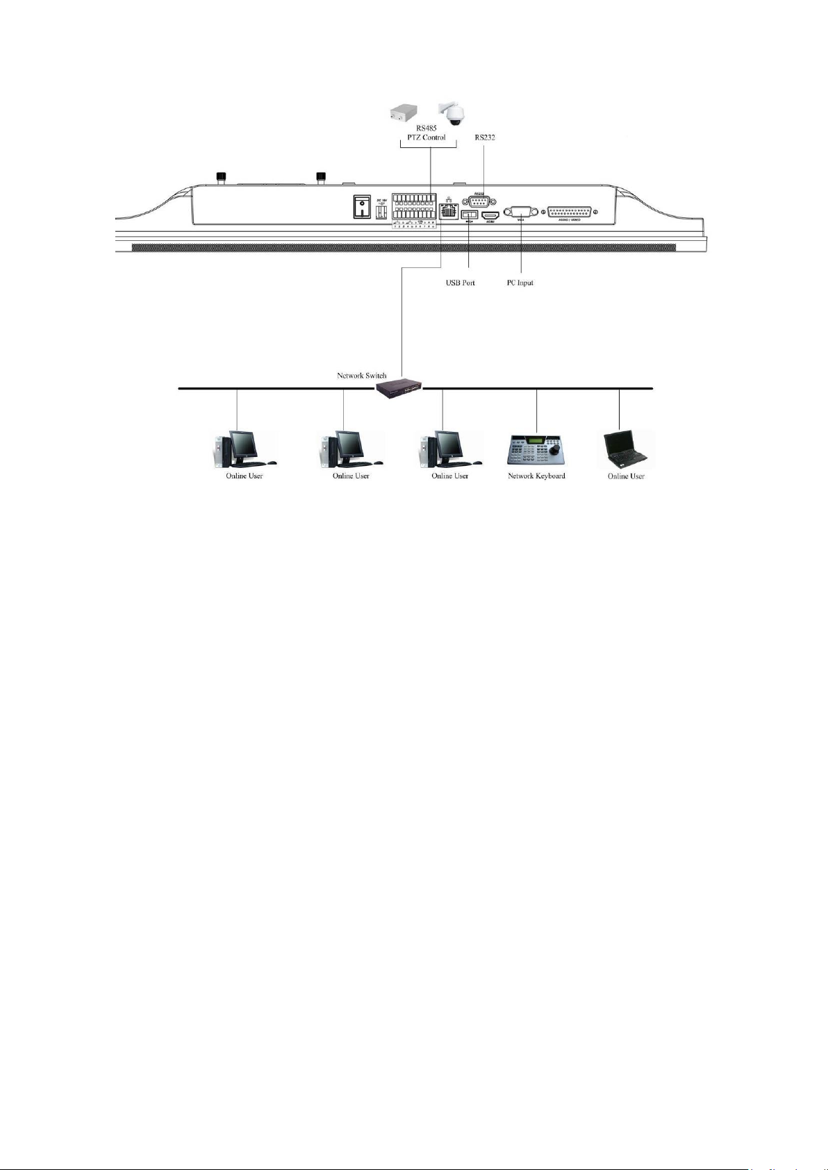
2.2 Connection Sample
Please refer to X281H281H281HFigure 2-3 for connection sample. The following figure is based on the 8channel series product.
Figure 2-3
2.3 Remote Control
The remote control interface is shown as in Figure 2-4.
Please note remote control is not our standard accessory and it is not included in the accessory
bag.
Page 17

17
Serial Number
Name
Function
1
Power button
Click it to boot up or shut down
the device.
2
Address
Click it to input device number,
so that you can control it.
3
Forward
Various forward speeds and
normal speed playback.
4
Slow play
Multiple slow play speeds or
normal playback.
5 Next record
In playback mode, playback the
next video.
6 Previous record
In playback mode, playback the
previous video.
7
Play/Pause
In pause mode, click this button
to realize normal playback.
In normal playback click this
button to pause playback.
In real-time monitor mode, click
this button to enter video search
menu.
8 Reverse/pause
Reverse playback pause mode,
click this button to realize normal
playback.
In reverse playback click this
button to pause playback.
Figure 2-4
Page 18

18
9 Cancel
Go back to previous menu or
cancel current operation (close
upper interface or control)
10
Record
Start or stop record manually
In record interface, working with
the direction buttons to select the
record channel.
11
Direction keys
Switch current activated control,
go to left or right.
In playback mode, it is to control
the playback process bar.
Aux function(such as switch the
PTZ menu)
12
Confirm /menu key
go to default button
go to the menu
13
Multiple-window switch
Switch between multiple-window
and one-window.
14
Auxiliary key
In 1-ch monitor mode: pop up
assistant function:PTZ control
and Video color.
Switch the PTZ control menu in
PTZ control interface.
In motion detection interface,
working with direction keys to
complete setup.
15
0-9 number key
Input password, channel or
switch channel.
Shift is the button to switch the
input method.
Left click
mouse
System pops up password input dialogue box if you have not logged in.
In real-time monitor mode, you can go to the main menu.
When you have selected one menu item, left click mouse to view menu
content.
Implement the control operation.
Modify checkbox or motion detection status.
Click combo box to pop up drop down list
2.4 Mouse Control
Page 19
19
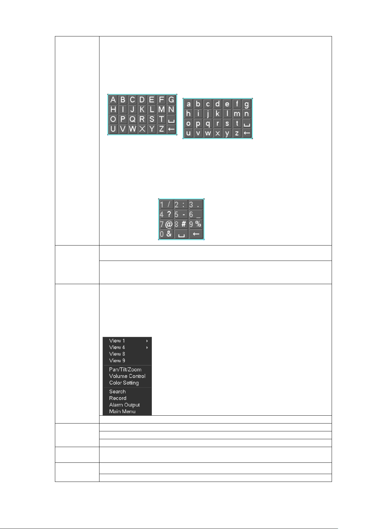
In input box, you can select input methods. Left click the corresponding
button on the panel you can input numeral/English character
(small/capitalized). Here ← stands for backspace button. _ stands for space
button.
In English input mode: _stands for input a backspace icon and ← stands for
deleting the previous character.
In numeral input mode: _ stands for clear and ← stands for deleting the
previous numeral.
When input special sign, you can click corresponding numeral in the front
panel to input. For example, click numeral 1 you can input―/‖ , or you can click
the numeral in the on-screen keyboard directly.
Double left
click mouse
Implement special control operation such as double click one item in the file
list to playback the video.
In multiple-window mode, double left click one channel to view in full-window.
Double left click current video again to go back to previous multiple-window
mode.
Right click
mouse
In real-time monitor mode, pops up shortcut menu: one-window, four-window,
eight-window and nine -window, Pan/Tilt/Zoom, volume control, color setting,
search, record, alarm output, main menu.
Among which, Pan/Tilt/Zoom and color setting applies for current selected
channel.
If you are in multiple-window mode, system automatically switches to the
corresponding channel.
Exit current menu without saving the modification.
Press
middle
button
In numeral input box: Increase or decrease numeral value.
Switch the items in the check box.
Page up or page down
Move
mouse
Select current control or move control
Drag mouse
Select motion detection zone
Select privacy mask zone.
Page 20

20
1. Loosen the two screws of the HDD
cover.
2. Remove the HDD cover from the rear panel
of the device.
3 Installation and Connections
Note: All the installation and operations here should conform to your local electric safety
rules.
3.1 Check Unpacked Device
When you receive the 22-inch combo DVR from the forwarding agent, please check whether
there is any visible damage. The protective materials used for the package of the 22-inch combo
DVR can protect most accidental clashes during transportation. Then you can open the box to
check the accessories.
Please check the items in accordance with the list on the warranty card (Remote control is
optional). Finally you can remove the protective film of the 22-inch combo DVR.
Note
Remote control is not a standard accessory and it is not included in the accessory bag.
3.2 About Front Panel and Real Panel
The model in the front panel is very important; please check according to your purchase order.
The label in the rear panel is very important too. Usually we need you to represent the serial
number when we provide the service after sales.
3.3 Device Installation
The series product supports two installation modes: desktop (default)/ wall-mount.
Please contact your local retailer to purchase wall-mount accessories.
3.4 HDD Installation
This series 22-inch combo DVR has only one SATA HDD.
You can refer to the Appendix for recommended HDD brand. You can select the capacity as your
requirement.
Please follow the instructions below to install the HDD.
Page 21

21
3. Connect the power cable, HDD cable
to the corresponding port of HDD.
4. Put the HDD cover back to the HDD
slot and then fix the two screws.
8. The HDD installation completed.
7. Put the HDD cover back to the HDD
slot and then fix the two screws.
5. Line up the four hole of the HDD cover
to the HDD.
6. Use the four screws to secure the HDD
and the HDD cover together. .
3.5 Connecting Power Supply
Please check input voltage and device power button match or not.
Page 22

22
We recommend you use UPS to guarantee steady operation, 22-inch combo DVR life span, and
other peripheral equipments operation such as cameras.
3.6 Connecting Video Input and Output Devices
3.6.1 Connecting Video Input
The video input interface is BNC. The input video format includes: PAL/NTSC BNC(1.0VB
B75Ω. It support the PC input too. See X283H283H283HFigure 3-1.
The video signal should comply with your national standards.
The input video signal shall have high SNR, low distortion; low interference, natural color and
suitable lightness.
Guarantee the stability and reliability of the camera signal:
The camera shall be installed in a cool, dry place away from direct sunlight, inflammable,
explosive substances and etc.
The camera and the 22-inch combo DVR should have the same grounding to ensure the normal
operation of the camera.
Guarantee stability and reliability of the transmission lineBTTTB
Please use high quality, sound shielded BNC. Please select suitable BNC model according to the
transmission distance.
If the distance is too long, you should use twisted pair cable, and you can add video
compensation devices or use optical fiber to ensure video quality.
You should keep the video signal away from the strong electromagnetic interference, especially
the high tension current.
Keep connection lugs in well contactBTTTB
The signal line and shielded wire should be fixed firmly and in well connection. Avoid dry joint,
lap welding and oxidation.BTTTB
P- P ,
Figure 3-1
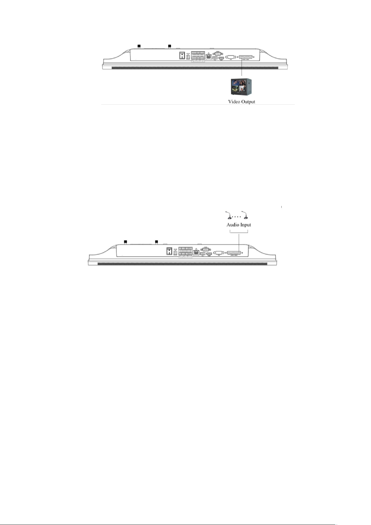
3.6.2 Connecting Video Output
Video output includes TBNC(PAL/NTSC BNC(1.0VP- P, 75Ω),HDMI output.
System supports BNC and HDMI output at the same time. See X284H 284H284HFigure 3-2.
When you are using pc-type monitor to replace the monitor, please pay attention to the following
points:
Using TV as video output device is not a reliable substitution method. You also need to reduce
the working hour and control the interference from power supply and other devices. The low
quality TV may result in device damage.
Page 23
23
Figure 3-2
3.7 Connecting Audio Input & Output, Bidirectional Audio
3.7.1 Audio Input
These series products adopt BNC port.
Due to high impedance of audio input, please use active sound pick-up. See X285H285H285HFigure 3-.3.
Audio transmission is similar to video transmission. Try to avoid interference, dry joint, loose
contact and it shall be away from high tension current.
Figure 3-3
3.7.2 Audio Output
The audio output signal parameter is usually over 200mv 1KΩ (BNC). It can directly connect to
low impedance earphone, active sound box or amplifier-drive audio output device.
If the sound box and the pick-up cannot be separated spatially, it is easy to arouse squeaking. In
this case you can adopt the following measures:
Use better sound pick-up with better directing property.
Reduce the volume of the sound box.
Using more sound-absorbing materials in decoration can reduce voice echo and improve
acoustics environment.
Adjust the layout to reduce happening of the squeaking.
Please refer to X286H286H286HFigure 3-4.
Page 24

24
Figure 3-4
3.8 Alarm Input and Output Connection
Please refer to the following sheet for alarm input and output connection. See X287H287H287HFigure 3-5.
Figure 3-5
There are two alarm input types for you to select: normal open (NO) and normal close (NC).
1. Alarm input
a. Please make sure alarm input mode is grounding alarm input.
b. Grounding signal is needed for alarm input.
c. When you are connecting two 22-inch combo DVRs or you are connecting one 22-inch combo
DVR and one other device, please use a relay to separate them,
2. Alarm output
The alarm output port should not be connected to high power load directly (It shall be less than
1A) to avoid high current which may result in relay damage. Please use the co contactor to
realize the connection between the alarm output port and the load.
3. How to connect PTZ decoder
a. Ensure the decoder has the same grounding with 22-inch combo DVR, otherwise you may not
control the PTZ. Shielded twisted wire is recommended and the shielded layer is used to connect
to the grounding.
b. Avoid high voltage. Ensure proper wiring and some thunder protection measures.
Page 25
25
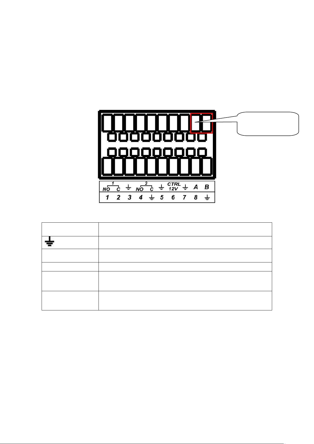
Parameter
Grounding Alarm
Ground line
1, 2, 3, 4.
5,6,7,8
Alarm input 1 to alarm input 8. It becomes valid in low voltage.
1-NO C,2-NO C
Two groups of normal open activation output (on-off).
CTRL 12V
It is to control the power output. Please shut down the power of the
device when you disable the alarm.
A/B
RS485 communication port. They are used to control devices such
as PTZ. Please parallel connect 120TΩ between A/B cables if there
are too many PTZ decoders.T
AB Connection
port
c. For too long signal wires, 120Ω should be parallel connected between A, B lines on the far end
to reduce reflection and guarantee the signal quality.
d. ―485 A, B‖ of 22-inch combo DVR cannot parallel connect with ―485 port‖ of other device.
e. The voltage between of A,B lines of the decoder should be less than 5v.
4. Please make sure the front-end device has soundly earthed.
Improper grounding may result in chip damage.
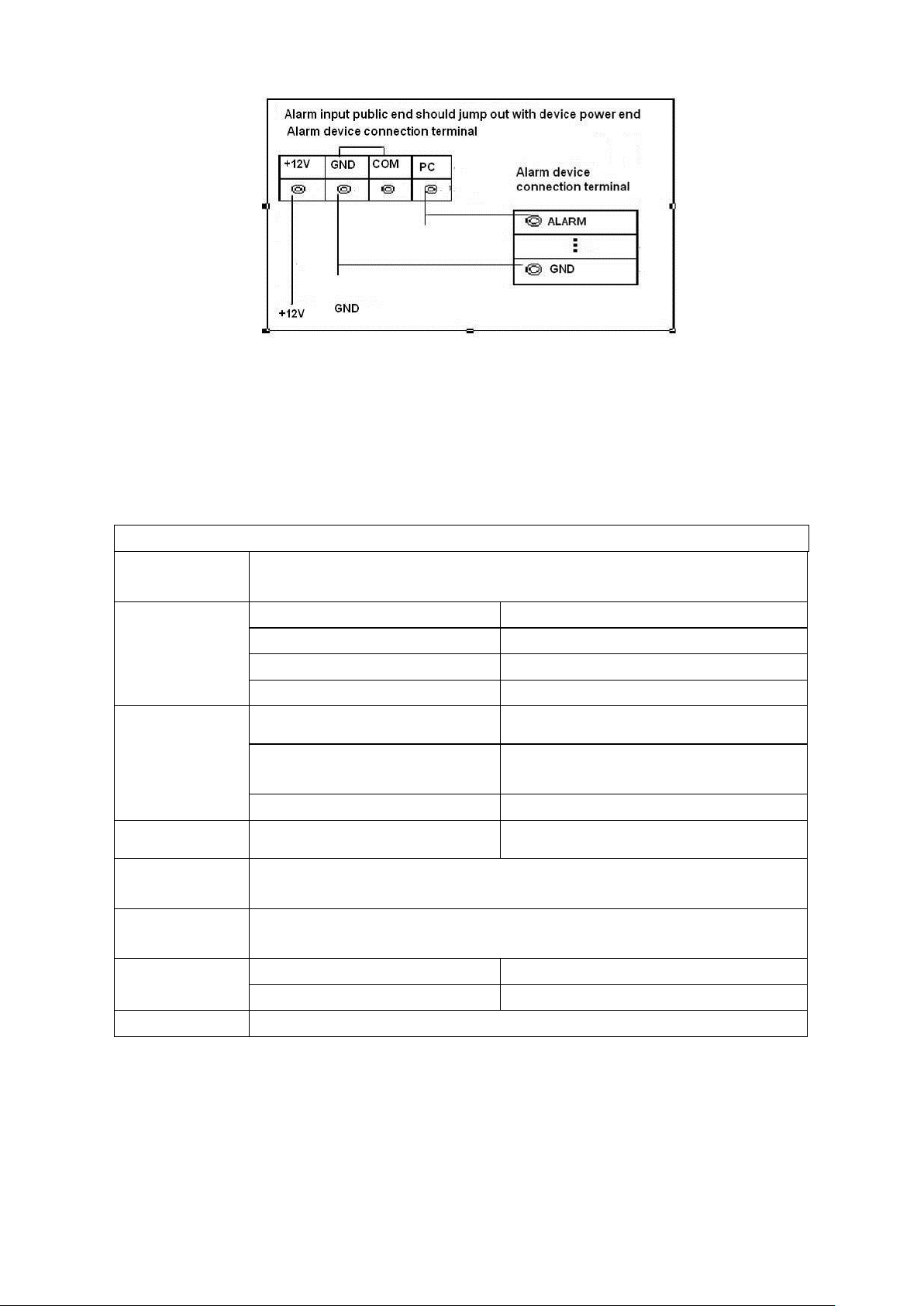
3.8.1 Alarm Input and Output Details
You can refer to the following sheet and X288H288H288HFigure 3-6 for alarm input and output information.
Figure 3-6
3.8.2 Alarm Input Port
Please refer to the following sheet for more information.
Normal open or Normal close type.
Please parallel connect COM end and GND end of the alarm detector (Provide external
power to the alarm detector).
Please parallel connect the Ground of the 22-inch combo DVR and the ground of the alarm
detector.
Please connect the NC port of the alarm sensor to the 22-inch combo DVR alarm
input(ALARM)
Use the same ground with that of 22-inch combo DVR if you use external power to the alarm
device.
Page 26
26
Model:
JRC-27F
Material of the
touch
Silver
Rating
(Resistance
Load)
Rated switch capacity
30VDC 2A, 125VAC 1A
Maximum switch power
125VA 160W
Maximum switch voltage
250VAC, 220VDC
Maximum switch currency
1A
Insulation
Between touches with same
polarity
1000VAC 1minute
Between touches with different
polarity
1000VAC 1minute
Between touch and winding
1000VAC 1minute
Surge voltage
Between touches with same
polarity
1500V (10×160us)
Length of open
time
3ms max
Length of close
time
3ms max
Longevity
Mechanical
50×106 times (3Hz)
Electrical
200×103 times (0.5Hz)
Temperature
-40℃ ~+70℃
Figure 3-7
3.8.3 Alarm Output Port
3-channel relay alarm output (NO contact). Provide external power to external alarm device.
To avoid overloading, please read the following relay parameters sheet carefully.
RS485 A/B cable is for the A/B cable of the PTZ decoder.
Relay Specification
3.9 RS232
You can connect the 22-inch combo DVR with POS or Keyboard through RS232.
With POS system, the 22-inch combo DVR can communicate through RS232 and network. For the
POS system, the 22-inch combo DVR can integrate the text content and even search the record
through the info.
Page 27

27
485 Port
The series 22-inch combo DVR also supports NKB operation. You can operate the 22-inch combo
DVR from the keyboard controls instead of using the control pad on the front panel of the unit.
To connect a NKB keyboard to the 22-inch combo DVR:
1. Assemble the KBD keyboard according to the instructions in its accompanying installation manual.
2. Connect the KBD keyboard into one of the RS232 ports on the 22-inch combo DVR or through
network.
3.10 RS485
When the 22-inch combo DVR receives a camera control command, it transmits that command up
the coaxial cable to the PTZ device. RS485 is a single-direction protocol; the PTZ device can’t return
any data to the unit. To enable the operation, connect the PTZ device to the RS485 (A,B) input on the
22-inch combo DVR. See X289H289H289HFigure 3-8.
Since RS485 is disabled by default for each camera, you must enable the PTZ settings first. This
series 22-inch combo DVR supports multiple protocols such as Pelco-D, Pelco-P.
To connect PTZ devices to the DVR:
1. Connect RS485 A, B on the DVR rear panel.
2. Connect the other end of the cable to the proper pins in the connector on the camera.
3. Please follow the instructions to configure a camera to enable each PTZ device on the 22-inch
combo DVR.
Figure 3-8
3.11 Other Interfaces
There are still other interfaces on the 22-inch combo DVR, such as USB ports. You can refer to the
X290H290H290HFigure 3-9X for more information.
Page 28
28
Figure 3-9
Page 29

29
4 Overview of Navigation and Controls
Before operation, please make sure:
You have properly installed HDD and all the cable connections.
The provided input power and the device power are matched.
The external power shall be DC 19V.
Always use the stable current, if necessary UPS is a best alternative measure.
The following operation is based on the 16-channel series product.
4.1 Login, Logout & Main Menu
4.1.1 Login
After system booted up, default video display is in multiple-window mode.
Click Enter or left click mouse, you can see the login interface. See Figure 4-1.
System consists of four accounts:
Username: admin. Password: admin. (administrator, local and network)
Username: 888888. Password: 888888. (administrator, local only)
Username: 666666. Passwords: 666666(Lower authority user who can only monitor, playback,
backup and etc.)
Username: default. Password: default(hidden user)
You can use USB mouse, front panel, remote control or keyboard to input. About input method:
Click to switch between numeral, English character (small/capitalized) and denotation.
Note:
For security reason, please modify password after you first login.
Within 30 minutes, three times login failure will result in system alarm and five times login failure
will result in account lock!
Figure 4-1
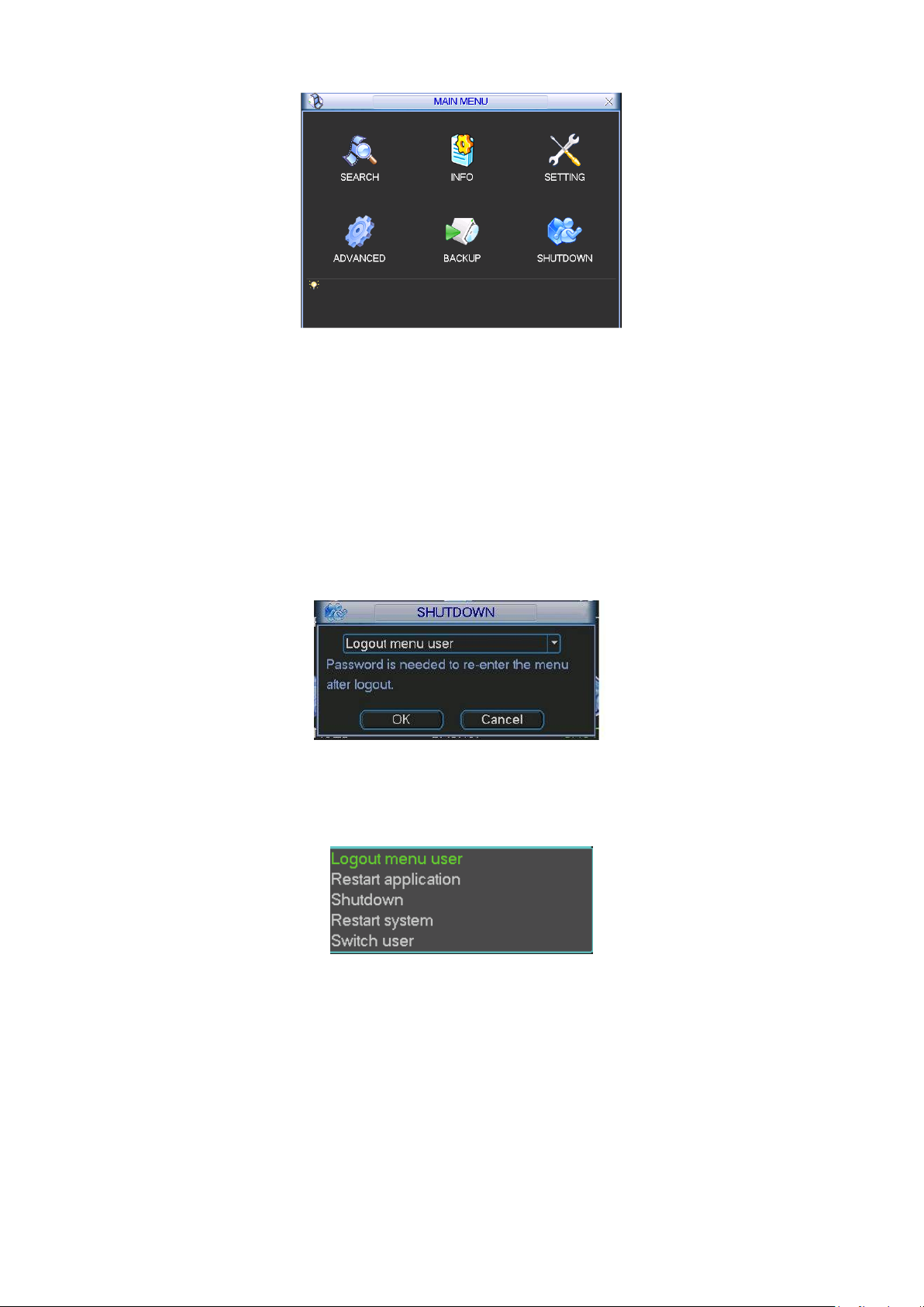
4.1.2 Main Menu
After you logged in, the system main menu is shown as below. See Figure 4-2.
There are total six icons: search, information, setting, backup, advanced and shutdown.
You can move the cursor to highlight the icon, and then double click mouse to enter the submenu.
Page 30
30
Figure 4-2
4.1.3 Shutdown
Important
Please open the HDD cover and then cut off the power before you replace the HDD!
There are two ways for you to shutdown the device.
One is from menu option (recommended):
In the main menu, click shutdown button, you can see an interface is shown as below. See
Figure 4-3.
Figure 4-3
There are several options for you. See Figure 4-4.
Please select the shutdown item to turn off the 22-inch combo DVR.
Figure 4-4
The other way is to press power button on rear panel to turn off the device.
4.1.4 Auto Resume after Power Failure
The system can automatically backup video and resume previous working status after power
failure.
4.1.5 Replace Button Battery
Please make sure to use the same battery model if possible.
Page 31

31
1
Recording status
3
Video loss
2
Motion detection
4
Camera lock
Please contact your local retailer before you replace the battery.
We recommend replace battery regularly (such as one-year) to guarantee system time
accuracy.
Before replacement, please save the system setup, otherwise, you may lose the data
completely!
4.2 Manual Record
4.2.1 Live Viewing
After you logged in, the system is in live viewing mode. You can see system date, time and
channel name. If you want to change system date and time, you can refer to general settings
(Main Menu->Setting->General). If you want to modify the channel name, please refer to the
display settings (Main Menu->Setting->Display)
4.2.2 Manual record
Note:
You need to have proper rights to implement the following operations. Please make sure the
HDD has been properly installed.
4.2.2.1 Manual record menu
There are two ways for you to go to manual record menu.
Right click mouse or in the main menu, Advanced->Manual Record.
In live viewing mode, click record button in the front panel or record button in the remote
control.
Manual record menu is shown as in Figure 4-5.
4.2.2.2 Basic operation
There are three statuses: schedule/manual/stop. Please highlight icon“○” to select
corresponding channel.
Manual: The highest priority. After manual setup, all selected channels will begin ordinary
recording.
Schedule: Channel records as you have set in recording setup (Main Menu->Setting-
>Schedule)
Stop: All channels stop recording.
4.2.2.3 Enable/disable record
Figure 4-5
Page 32

32
Please check current channel status: ―○‖ means it is not in recording status, ―●‖ means it is in
recording status.
You can use mouse or direction key to highlight channel number. See Figure 4-6.
Figure 4-6
4.2.2.4 Enable all channel recording
Highlight ○ below All, you can enable all channel recording.
All channel schedule record
Please highlight ―ALL‖ after ―Schedule‖. See Figure 4-7.
When system is in schedule recording, all channels will record as you have previously set
(Main menu->Setting->Schedule).
The corresponding indication light in front panel will turn on.
Figure 4-7
All channel manual record
Please highlight “ALL” after “Manual.” See Figure 4-8.
When system is in manual recording, all scheduled set up you have set in will be null ((Main
menu->Setting->Schedule)).
You can see indication light in front panel turns on, system begins manual record now.
Figure 4-8
Page 33

33
SN
Name
Function
1
Display
Here is to display the searched file.
1 2 3
4
5 6 7 8 9
10
11
4.2.2.5 Stop all channel recording
Please highlight “ALL” after “Stop”. See Figure 4-9.
System stops all channel recording no matter what mode you have set in the menu (Main
menu->Setting->Schedule)
Figure 4-9
4.3 Search & Playback
Click search button in the main menu, search interface is shown as below. See Figure 4-10.
Usually there are three file types:
R: Regular recording file.
A: External alarm recording file.
M: Motion detection recording file
Please refer to the following sheet for more information.
Figure 4-10
Page 34

34
window
Support 1/4/9/16-window playback.
2
Search
type
Here you can search the recorded file.
3
Calendar
The blue highlighted date means there are recorded files. Otherwise, there is no
file.
In any play mode, click the date you want to see, you can see the corresponding
record file trace in the time bar.
4
Playback
mode
and
channel
selection
pane.
Playback mode:1/4/9/16. (It may vary due to different series.)
In 1-window playback mode: you can select 1-16 channels.
In 4-window playback mode: you can select 4 channels according to your
requirement.
In 9-window playback mode, you can switch between 1-9 and 10-16 channels.
In 16-window playback mode, you can switch between1-16 and 17-32
channels.
The time bar will change once you modify the playback mode or the channel
option.
5
File list
switch
button
Double click it; you can view the recorded file list of current day.
The file list is to display the first channel of the record file.
The system can display max 128 files in one time. Use the / or the mouse to
view the file. Select one item, and then double click the mouse or click the ENTER
button to playback.
You can input the period in the following interface to begin accurate search.
File type: R—regular record; A—external alarm record; M—Motion detect
record.
6
Playback
control
pane.
►/
Play/Pause
There are three ways for you to begin playback.
The play button
Double click the valid period of the time bar.
Double click the item in the file list.
In slow play mode, click it to switch between play/pause.
■
Stop
Backward play
In normal play mode, left click the button, the file begins backward play.
Click it again to pause current play.
In backward play mode, click ►/ to restore normal play.
│/
│
In playback mode, click it to play the next or the previous section. You can
click continuously when you are watching the files from the same channel.
In normal play mode, when you pause current play, you can click │ and
│ to begin frame by frame playback.
In frame by frame playback mode, click ►/ to restore normal playback.
►
Slow play
In playback mode, click it to realize various slow play modes such as slow
play 1, slow play 2, and etc.
Fast forward
In playback mode, click to realize various fast play modes such as fast
play 1,fast play 2 and etc.
Note: The actual play speed has relationship with the software version.
Smart search. Please refer to the SN12 for detailed information.
The volume of the playback
Page 35

35
7
Time bar
It is to display the record type and its period in current search criteria.
In 4-window playback mode, there are corresponding four time bars. In other
playback mode, there is only one time bar.
Use the mouse to click one point of the color zone in the time bar, system begins
playback.
The time bar is beginning with 0 o'clock when you are setting the configuration.
The time bar zooms in the period of the current playback time when you are
playing the file.
The green color stands for the regular record file. The red color stands for the
external alarm record file. The yellow stands for the motion detect record file.
8
Time bar
unit
●The option includes: 24H, 12H, 1H and 30M. The smaller the unit, the larger the
zoom rate. You can accurately set the time in the time bar to playback the record.
The time bar is beginning with 0 o'clock when you are setting the configuration.
The time bar zooms in the period of the current playback time when you are
playing the file.
9
Backup
Select the file(s) you want to backup from the file list. System max supports files
from four channels. Then click the backup button, now you can see the backup
menu. Click the start button to begin the backup operation.
Check the file again you can cancel current selection.
System max supports to display 32 files from one channel.
10
Clip
It is to edit the file.
●Please play the file you want to edit and then click this button when you want to
edit. You can see the corresponding slide bar in the time bar of the corresponding
channel. You can adjust the slide bar or input the accurate time to set the file end
time. Click this button again and then save current contents in a new file. .
11
Record
type
In any play mode, the time bar will change once you modify the search type.
12
Smart
search
When system is playing, you can select a zone in the window to begin motion
detect. Click the motion detect button to begin play.
Current button is null once the motion detect play has begun.
The system will take the whole play zone as the motion detect region by
default.
The motion detect play stopped once you switch the play file.
Operations such as set time bar, click the play button, or any file list operation
will stop current motion detect play.
Other Functions
13
Other channel
synchronization switch to
play when playback
When playing the file, click the number button of the remote
control, system can switch to the same period of the
corresponding channel to play.
14
Digital zoom
When the system is in full-screen playback mode, left click
the mouse in the screen. Drag your mouse in the screen to
select a section and then left click mouse to realize digital
zoom. You can right click mouse to exit.
Please note the smart search function has relationship with the actual software version.
Please contact your local retailer or visit our website to get the latest software version.
4.4 Schedule
After system booted up, it is in default 24-hour regular mode. You can set record type and
time in schedule interface.
4.4.1 Schedule Menu
In the main menu, from setting to schedule, you can go to schedule menu. See Figure 4-11.
Channel: Please select the channel number first. You can select “all” if you want to set for
the whole channels.
Week day: There are eight options: ranges from Saturday to Sunday and all.
Page 36

36
Pre-record: System can pre-record the video before the event occurs into the file. The value
ranges from 1 to 30 seconds depending on the bit stream.
Snapshot: You can enable this function to snapshoot image when alarm occurs.
Record types: There are four types: regular, motion detection (MD), Alarm, MD & alarm.
Please highlight icon to select the corresponding function. After completing all the setups
please click save button, system goes back to the previous menu.
At the bottom of the menu, there are color bars for your reference. Green color stands for
regular recording, yellow color stands for motion detection and red color stands for alarm
recording. The white means the MD and alarm record is valid. Once you have set to record
when the MD and alarm occurs, system will not record neither motion detect occurs nor the
alarm occurs.
Figure 4-11
4.4.1.1 Quick Setup
This function allows you to copy one channel setup to another. After setting in channel 1, you can
click paste button and turn to channel 2 and then click copy button. You can finish setting for one
channel and then click save button or you can finish all setup and then click save button to
memorize all the settings.
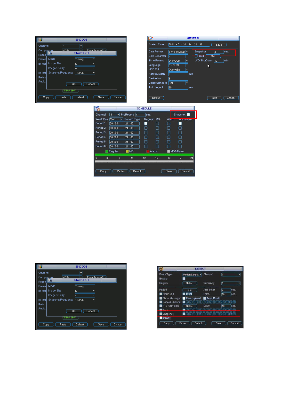
4.4.2 Snapshot
4.4.2.1 Schedule Snapshot
In Encode interface, click snapshot button to input snapshot mode, size, quality and
frequency.
In General interface please input upload interval.
In Schedule interface, please enable snapshot function.
Page 37
37
Please refer to the following figure for detailed information. See Figure 4-12.
Figure 4-12
4.4.2.2 Activation Snapshot
Please follow the steps listed below to enable the activation snapshot function. After you
enabled this function, system can snapshot when the corresponding alarm occurred.
In Encode interface, click snapshot button to input snapshot mode, size, quality and
frequency.
In General interface please input upload interval.
In Detect interface please enable snapshot function for specified channels. Or in alarm
interface please enable snapshot function for specified channels.
Please refer to the following figure for detailed information. See Figure 4-13.
Page 38
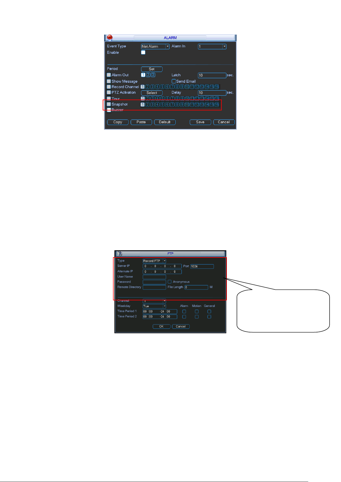
38
Please input the
corresponding information
here, if you just upload the
image FTP.
Figure 4-13
4.4.2.3 Priority
Please note the activation snapshot has the higher priority than schedule snapshot. If you
have enabled these two types at the same time, system can activate the activation snapshot
when alarm occurs, and otherwise system just operates the schedule snapshot.
4.4.3 Image FTP
In Network interface, you can set FTP server information. Please enable FTP function and
then click save button. See Figure 4-14.
Please boot up corresponding FTP server.
Please enable schedule snapshot (Chapter 4.4.2.1) or activation snapshot (Chapter 4.4.2.2)
first, now system can upload the image file to the FTP server.
4.5 Detect
4.5.1 Go to Detect Menu
In the main menu, from Setting to Detect, you can see motion detect interface. See X302H302H302HFigure
4-16X. There are three detection types: motion detection, video loss, camera masking.
4.5.2 Motion Detect
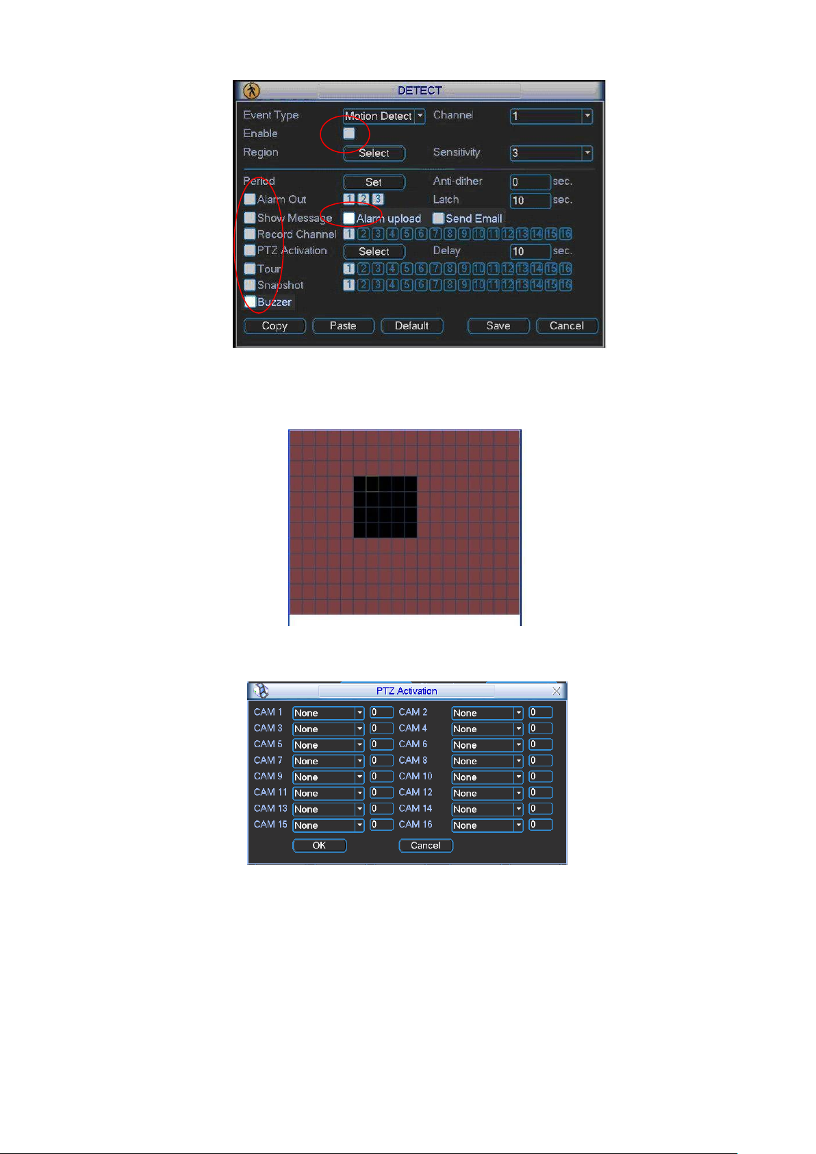
Detection menu is shown as below. See Figure 4-15.
Event type: from the dropdown list you can select motion detection type.
Figure 4-14
Page 39

39
Channel: select the channel to activate recording function once alarm occurred. Please make
sure you have set MD record in encode interface(Main Menu->Setting->Schedule) and
schedule record in manual record interface(Main Menu->Advanced->Manual Record)
Latch: when motion detection complete, system auto delays detecting for a specified time.
The value ranges from 10-300(Unit: second)
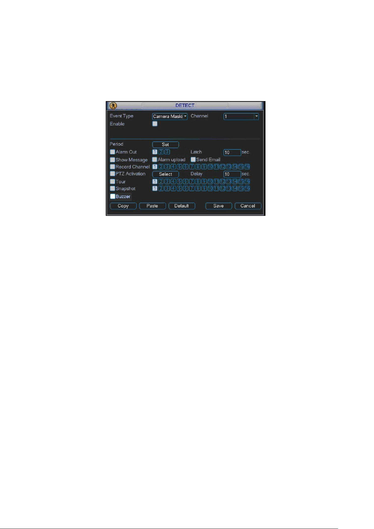
Region: Click select button, the interface is shown as in Figure 4-16. Here you can set
motion detection zone. There are 396(22*18 PAL)/330(22*15 NTSC) small zones. The green
zone is current cursor position. Grey zone is the motion detection zone. Black zone is the
disarmed zone. You can click Fn button to switch between the arm mode and disarm mode.
In arm mode, you can click the direction buttons to move the green rectangle to set the
motion detection zone. After you completed the setup, please click ENTER button to exit
current setup. Do remember click save button to save current setup. If you click ESC button
to exit the region setup interface system will not save your zone setup.
Sensitivity: System supports 6 levels. The sixth level has the highest sensitivity.
Show message: System can pop up a message to alarm you in the local host screen if you
enabled this function.
Alarm upload: System can upload the alarm signal to the network (including alarm centre)
if you enabled current function.
Send email: System can send out email to alert you when alarm occurs.
PTZ activation: Here you can set PTZ movement when alarm occurs. Such as go to preset,
tour &pattern when there is an alarm. Click “select” button, you can see an interface is
shown as in Figure 4-17. Please note motion detect can only activate the preset.
Period: Click set button, you can see an interface is shown as in Figure 4-18. Here you can
set for business day and non-business day. In Figure 4-18, click set button, you can see an
interface is shown as in Figure 4-19. Here you can set your own setup for business day and
non-business day.
Anti-dither: Here you can set anti-dither time.
Alarm output: when alarm occurred, system can upload alarm to the network (Including the
alarm centre.)
Tour: Here you can enable tour function when alarm occurs. It is a one-window tour. Please
go to chapter 5.3.9 Display for tour interval setup.
Buzzer: Highlight icon to enable this function. The buzzer beeps when alarm occurs.
Please highlight icon to select the corresponding function. After all the setups please click
save button, system goes back to the previous menu.
Note:
In motion detection mode, you can not use copy/paste to set channel setup since the video in
each channel may not be the same.
In X309H309H309HFigure 4-17X, you can left click mouse and then drag it to set a region for motion detection.
Click Fn to switch between arm/withdraw motion detection. After setting, click enter button to exit.
Page 40
40
Figure 4-15
Figure 4-16
Figure 4-17
Page 41

41
Figure 4-18
Figure 4-19
4.5.3 Video Loss
In Figure 4-15, select video loss from the type list. You can see the interface is shown as in
Figure 4-20.This function allows you to be informed when video loss phenomenon occurred.
You can enable alarm output channel and then enable show message function.
Tips:
You can enable preset/tour/pattern activation operation when video loss occurs.
Please refer to chapter 4.5.2 motion detection for detailed information.
Figure 4-20
4.5.4 Camera Masking
When someone viciously masks the lens, or the output video is in one-color due to the
environments light change, the system can alert you to guarantee video continuity. Camera
masking interface is shown as in Figure 4-21.
Page 42
42
Tips:
You can enable preset/tour/pattern activation operation when video loss occurs.
Please refer to chapter 4.5.2 motion detection for detail information.
Note:
In Detect interface, copy/paste function is only valid for the same type, which means you can
not copy a channel setup in video loss mode to camera masking mode.
Figure 4-21
4.6 Alarm Setup and Alarm Activation
Before operation, please make sure you have properly connected alarm devices such as
buzzer.
4.6.1 Go to alarm setup interface
In the main menu, from Setting to Alarm, you can see alarm setup interface. See Figure 4-22.
4.6.2 Alarm setup
Alarm interface is shown as below. See Figure 4-22.
Alarm in: Here is for you to select channel number.
Event type: There are two types. One is local input and the other is network input.
Type: normal open or normal close.
PTZ activation: Here you can set PTZ movement when alarm occurs. Such as go to preset,
tour& pattern when there is an alarm. Click ―select‖ button, you can see an interface is
shown as in Figure 4-23.
Period: Click set button, you can see an interface is shown as in Figure 4-24.Here you can
set for business day and non-business day. In Figure 4-24, click set button, you can see an
interface is shown as in Figure 4-25. Here you can set your own setup for business day and
non-business day.
Anti-dither: Here you can set anti-dither time.
Show message: System can pop up a message to alarm you in the local host screen if you
enabled this function.
Alarm upload: System can upload the alarm signal to the network (including alarm centre)
if you enabled current function.
Send email: System can send out email to alert you when alarm occurs.
Page 43

43
Record channel: you can select proper channel to record alarm video (Multiple choices). At
the same time you need to set alarm record in schedule interface (Main Menu->Setting>Schedule) and select schedule record in manual record interface (Main Menu->Advance>Manual Record).
Latch: Here is for you to set proper delay duration. Value ranges from 10 to 300 seconds.
System automatically delays specified seconds in turning off alarm and activated output after
external alarm cancelled.
Tour: Here you can enable tour function when alarm occurs. It is a one-window tour: Please
go to chapter 5.3.9 Display for tour interval setup.
Buzzer: Highlight icon to enable this function. The buzzer beeps when alarm occurs.
For snapshot operation, please refer to chapter 4.4.2.
Please highlight icon to select the corresponding function. After setting all the setups
please click save button, system goes back to the previous menu.
Figure 4-22
Figure 4-23
Page 44

44
Figure 4-24
Figure 4-25
4.7 Backup
22-inch combo DVR supports USB device backup and network download. Here we introduce
USB backup first. You can refer to Chapter 7 Web Operation for network download backup
operation.
4.7.1 Detect Device
Click backup button, you can see an interface is shown as in Figure 4-26.Here is for you to
view devices information such as total capacity and status.
You can view backup device name and its total space and free space. The device includes
USB burner, flash disk, SD card and portable HDD.
Figure 4-26
Page 45

45
4.7.1 Backup
Select backup device and then set channel, file start time and end time.
Click add button, system begins search. All matched files are listed below. System
automatically calculates the capacity needed and remained. See Figure 4-27.
system only backup files with a √ before channel name. You can use Fn or cancel button to
delete √ after file serial number.
Click backup button, you can backup selected files. There is a process bar for you reference.
When the system completes backup, you can see a dialogue box prompting successful
backup.
Figure 4-27
Click backup button, system begins burning. At the same time, the backup button becomes
stop button. You can view the remaining time and process bar at the left bottom. See Figure
4-28.
Figure 4-28
The file name format usually is: SN_CH+channel number+time Y+M+D+H+M+S. In the file
name, the YDM format is the same as you set in general interface. (Main Menu ->Setting >General).File extension name is .dav.
Tips:
During backup process, you can click ESC to exit current interface for other operation. The
system will not terminate backup process.
Note:
When you click stop button during the burning process, the stop function becomes activated
immediately. For example, if there are ten files, when you click stop system just backup five
files, system only save the previous 5 files in the device (But you can view ten file names).
Page 46

46
4.8 PTZ Control and Color Setup
Note: All the operations here are based on PELCOD protocol. For other protocols, there
might be a little difference.
4.8.1 Cable Connection
Please follow the procedures below to go on cable connection
Connect the dome RS485 port to 22-inch combo DVR 485 port.
Connect dome video output cable to 22-inch combo DVR video input port.
Connect power adapter to the dome.
4.8.2 PTZ Setup
Note: The camera video should be in the current screen. Before setup, please check the
following connections are right:
PTZ and decoder connection is right. Decoder address setup is right.
Decoder A (B) line connects with 22-inch combo DVR A (B) line.
Boot up the 22-inch combo DVR, input user name and password.
In the main menu, click setting, and then click Pan/Tilt Control button. The interface is shown
as in Figure 4-29. Here you can set the following items:
Channel: select the current camera channel.
Protocol: select corresponding PTZ protocol(such as PELCOD)
Address: default address is 1.
Baud rate: select corresponding baud rate. Default value is 9600.
Data bits: select corresponding data bits. Default value is 8.
Stop bits: select corresponding stop bits. Default value is 1.
Parity: there are three options: odd/even/none. Default setup is none.
Figure 4-29
After completing all the setting please click save button.
In one window display mode, right click mouse (click ―Fn‖ Button in the front panel or click
―Fn‖ key in the remote control). The interface is shown as in Figure 4-30.
Page 47
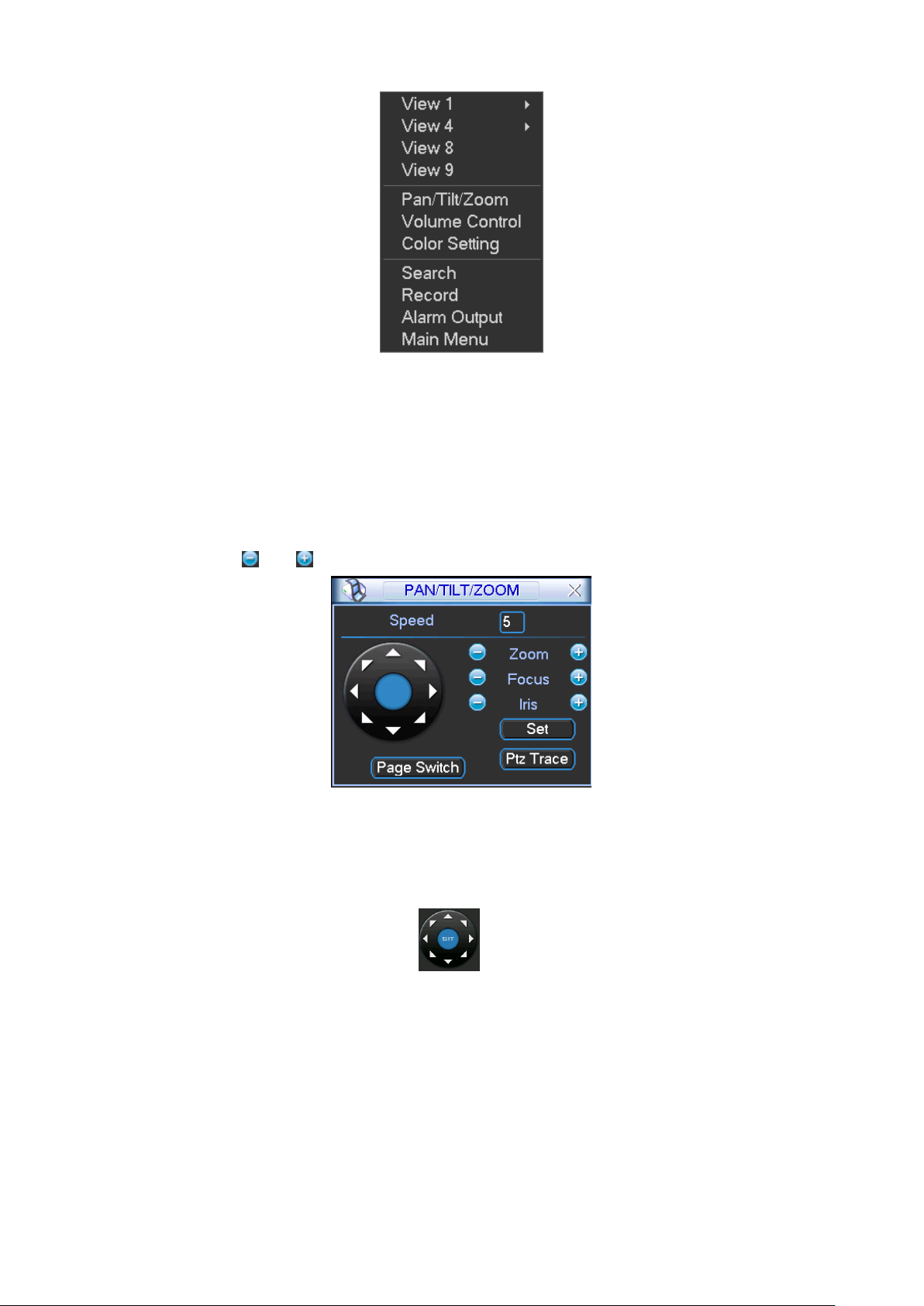
47
Figure 4-30
Click Pan/Tilt/Zoom, the interface is shown as below. See Figure 4-31.
Here you can set the following items:
Step: value ranges fro 1 to 8.
Zoom
Focus
Iris
Please click icon and to adjust zoom, focus and iris.
Figure 4-31
In Figure 4-31, please click direction arrows (See Figure 4-32.) to adjust PTZ position. There are
total 8 direction arrows.
Figure 4-32
4.8.3 3D Intelligent Positioning Key
In the middle of the eight direction arrows, there is a 3D intelligent positioning key. See Figure
4-33. Please make sure your protocol supports this function and you need to use mouse to
control.
Click this key, system goes back to the single screen mode. Drag the mouse in the screen to
adjust section size. The dragged zone supports 4X to 16X speeds. It can realize PTZ
automatically. The smaller zone you dragged, the higher the speed.
Page 48

48
Name
Function
key
function
Shortcut
key
Function
key
function
Shortcut
Key
Zoom
Near
Far
Focus
Near
│
Far
►│
Iris close
Open
Figure 4-33
Here is a sheet for you reference.
4.9 Preset/ Patrol/Pattern/Scan
In Figure 4-31, please click the ―set‖ button. The interface is shown as below. See Figure 4-34.
Here you can set the following items:
Preset
Tour
Pattern
Border
Figure 4-34
In Figure 4-31, click page switch button, the interface is shown as in Figure 4-35
Here you can activate the following functions:
Preset
Tour
Pattern
Auto scan
Auto pan
Flip
Reset
Page switch
Figure 4-35
Page 49

49
Note:
Preset, tour and pattern all need the value to be the control parameter. You can define it as
you require.
You need to refer to your speed dome user’s manual for Aux definition. In some cases, it
can be used for special process.
The following setups are usually operated in the Figure 4-31, Figure 4-34 and Figure 4-35 .
4.9.1Preset Setup
In Figure 4-31 use eight direction arrows to adjust camera to the proper position.
In Figure 4-34, click preset button and input preset number. The interface is shown as in Figure
4-36.
Now you can add this preset to one tour.
Figure 4-36
4.9.2 Activate Preset
In Figure 4-35, please input preset number in the No. blank, and click preset button.
4.9.3 Patrol setup (Tour Setup)
In Figure 4-34, click patrol button. The interface is shown as in Figure 4-37.Input preset number
and add this preset to a patrol (tour). For each patrol (tour), you can input max 80 presets.
Figure 4-37
4.9.4 Activate Patrol (tour)
In Figure 4-34, input patrol (tour) number in the No. blank and click patrol button
4.9.5 Pattern Setup
In Figure 4-34, click pattern button and then click ―begin‖ button. The interface is shown as in
Figure 4-38. Then you can go to Figure 4-31 to modify zoom, focus, and iris.
Go back to Figure 4-38 and click ―end‖ button. You can memorize all these operations as pattern
1.
Page 50

50
Figure 4-38
4.9.6 Activate Pattern Function
In Figure 4-35, input mode value in the No. blank, and click pattern button.
4.9.7 Auto Scan Setup
In Figure 4-34, click border button. The interface is shown as in Figure 4-39.
Please go to Figure 4-31, use direction arrows to select camera left limit
Then please go to Figure 4-39 and click left limit button
Repeat the above procedures to set right limit.
Figure 4-39
4.9.8 Activate Auto Scan
In Figure 4-35, click ―Auto Scan‖ button, the system begins auto scan. Correspondingly, the auto
scan button becomes Stop button. Click stop button to terminate scan operation.
4.10 Flip
In Figure 4-35, click page switch button, you can see an interface is shown as below. See Figure
4-40. Here you can set auxiliary function. The aux value has relation ship with the Aux button of
the decoder.
Click page switch button again, system goes back to Figure 4-31
Figure 4-40
Page 51

51
Please note the direction buttons are to control the speed dome menu. The button definition is
defined by the speed dome protocol. The button becomes grey and invalid if current protocol
does not support this function.
The up/down button is to switch between the items and the left/right button is to modify the setup.
Page 52

52
5 Understanding of Menu Operations and Controls
5.1 Menu Tree
This series 22-inch combo DVR menu tree is shown as below.
Backup
Information
HDD Info
BPS
Log
Version
Online Users
Setting
General
Encode
Schedule
RS232
Menu Network
Alarm
Detect
Pan/ Tilt/Zoom
Display
Default
Search
Advanced
HDD Management
Alarm Output
Abnormity
Manual Record
Account
Auto Maintain
TV Adjust
Shutdown
5.2 Main Menu
After you logged in, the system main menu is shown as below. See X355H355H355HFigure 5-1.X There are total
six icons: search, Information, setting, backup, advanced and shutdown. Move the cursor to
highlight the icon, then double click mouse to enter the sub-menu.
Page 53

53
Figure 5-1
5.3 Setting
In main menu, highlight setting icon and double click mouse. System setting interface is shown
as below. See X356H356H356HFigure 5-2.X
Figure 5-2
5.3.1 General
General setting includes the following items. See X357H357H357HFigure 5-3X.
System time: Here is for you to set system time
Date format: There are three types: YYYYY-MM-DD: MM-DD-YYYYY or DD-MM-YYYY.
Snapshot: Here you can set snapshot interval.
Date separator: There are three denotations to separate date: dot, beeline and solidus.
DST: Here you can set DST time and date. Please enable DST function and then click set
button. You can see an interface is shown as in X358H358H358H Figure 5-4X. Here you can set start time and
end time by setting corresponding week setup. In X359H359H359HFigure 5-4X, enable date button, you can
see an interface is shown as in X360H360H360HFigure 5-5X. Here you can set start time and end time by
setting corresponding date setup.
Time format: There are two types: 24-hour mode or 12-hour mode.
LCD shutdown: Here you can set the LCD auto shutdown time after system is invalid for the
specified time. The max setup is 120 minutes.
Page 54
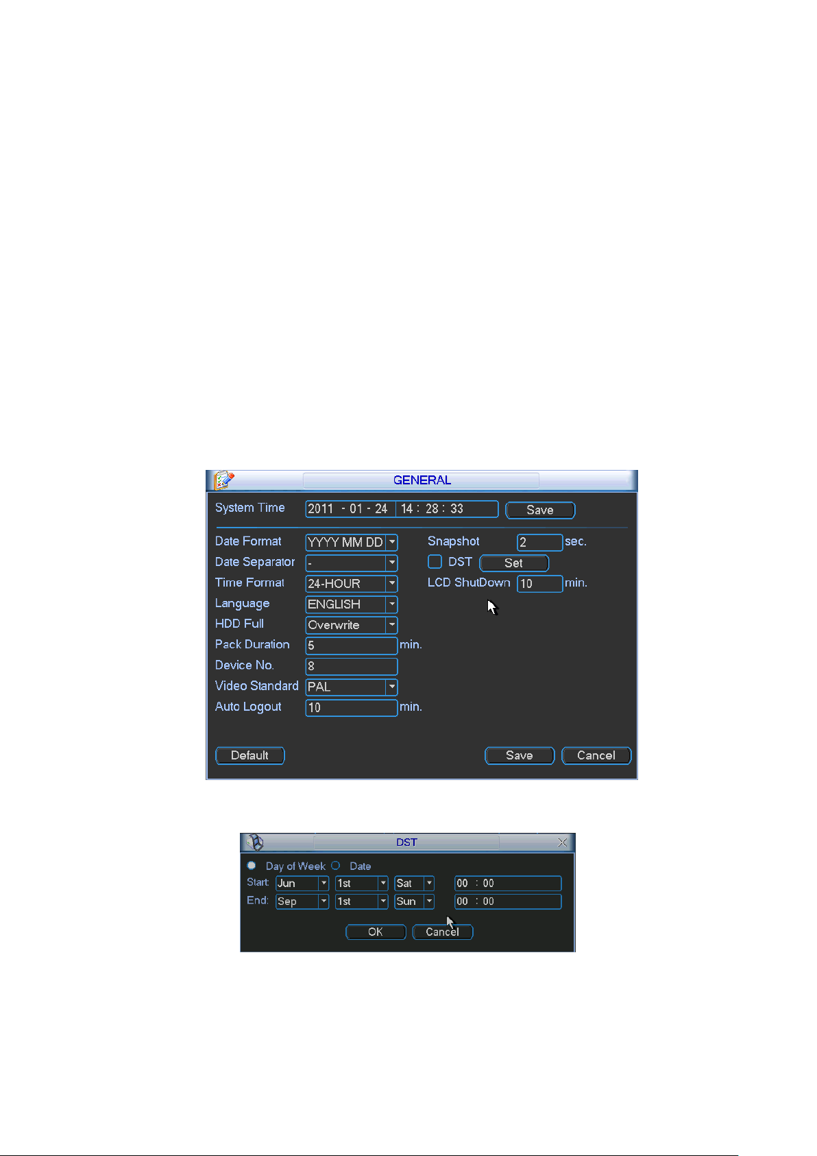
54
Language: System supports various languages: Chinese (simplified), Chinese (Traditional),
English, Italian, Japanese, French, Spanish (All languages listed here are optional. Slight
difference maybe found in various series.)
HDD full: Here is for you to select working mode when hard disk is full. There are two options:
stop recording or rewrite. If current working HDD is overwritten or the current HDD is full
while the next HDD is no empty, then system stops recording, If the current HDD is full and
then next HDD is not empty, then system overwrites the previous files.
Pack duration: Here is for you to specify record duration. The value ranges from 60 to 120
minutes. Default value is 60 minutes.
DVR No: When you are using one remote control (not included in the accessory bag) to
control several DVRs, you can give a name to each DVR for your management.
Video standard: There are two formats: NTSC and PAL.
Auto logout: Here is for you to set auto logout interval once login user remains inactive for a
specified time. The value ranges from 0 to 60 minutes.
Note:
Since system time is very important, do not modify time casually unless there is a must!
Before your time modification, please stop record operation first!
After completing all the setups please click save button, system goes back to the previous menu.
Figure 5-3
Figure 5-4
Page 55

55
Figure 5-5
5.3.2 Encode
Encode setting includes the following items. See X361H361H361HFigure 5-6.X
Channel: Select the channel you want.
Compression: System supports H.264.
Resolution: System supports various resolutions, you can select from the dropdown list. For
this model, main stream supports D1/CIF/QCIF. Please note the resolution may vary due to
different channels. The extra stream of the 1-16 channels supports QCIF only.
Frame rate: It ranges from 1f/s to 25f/s in NTSC mode and 1f/s to 30f/s in PAL mode.
Note:
For the 8-ch (16-ch) series 22-inch combo DVR:
If the 1-ch (or the 9-ch) resolution is D1 (PAL: 25f/s. NTSC: 30f/s), the rest channels (2-8-ch
or 10-16-ch) support CIF/QCIF.
If the 1-ch (or the 9-ch) resolution is D1 (PAL: ≤ 6/fs, NTSC: ≤7f/s), the rest channels (2-8-
chnanel or 10-16-channel) support D1 (PAL: ≤6f/s. NTSC: ≤7f/s)/CIF/QCIF.
Bit rate type: System supports two types: CBR and VBR. In VBR mode, you can set video
quality.
Quality: There are six levels ranging from 1 to 6. The sixth level has the highest image
quality.
Video/audio: You can enable or disable the video/audio.
Overlay: Click overlay button, you can see an interface is shown in X362H 362H362HFigure 5-7X
Cover area (Privacy mask): Here is for you to set privacy mask section. You can drag you
mouse to set proper section size. In one channel video, system max supports 4 zones.
Preview/monitor: privacy mask has two types. Preview and Monitor. Preview means the
privacy mask zone can not be viewed by user when system is in preview status. Monitor
means the privacy mask zone can not be view by the user when system is in monitor status.
Time display: You can select system displays time or not when you playback. Please click
set button and then drag the title to the corresponding position in the screen.
Channel display: You can select system displays channel number or not when you playback.
Please click set button and then drag the title to the corresponding position in the s creen.
Please highlight icon to select the corresponding function.
Page 56

56
Figure 5-6
Figure 5-7
5.3.3 Schedule
Please refer to chapter 4.4 schedule.
5.3.4 RS232
RS232 interface is shown as below. There are five items. SeeX363H363H363H Figure 5-8
Function: There are various devices for you to select. Console is for serial port or min-end
platform to upgrade program. Keyboard is for you to use special keyboard to control current
device.
Baud rate: You can select proper baud rate.
Data bit: You can select proper data bit. The value ranges from 5 to 8.
Stop bit: There are two values: 1/2.
Parity: There are five choices: none/odd /even/mark/space.
System default setup is:
Function: Console
Baud rate:115200
Data bit:8
Stop bit:1
Parity: None
After completing all the setups please click save button, system goes back to the previous menu.
Page 57
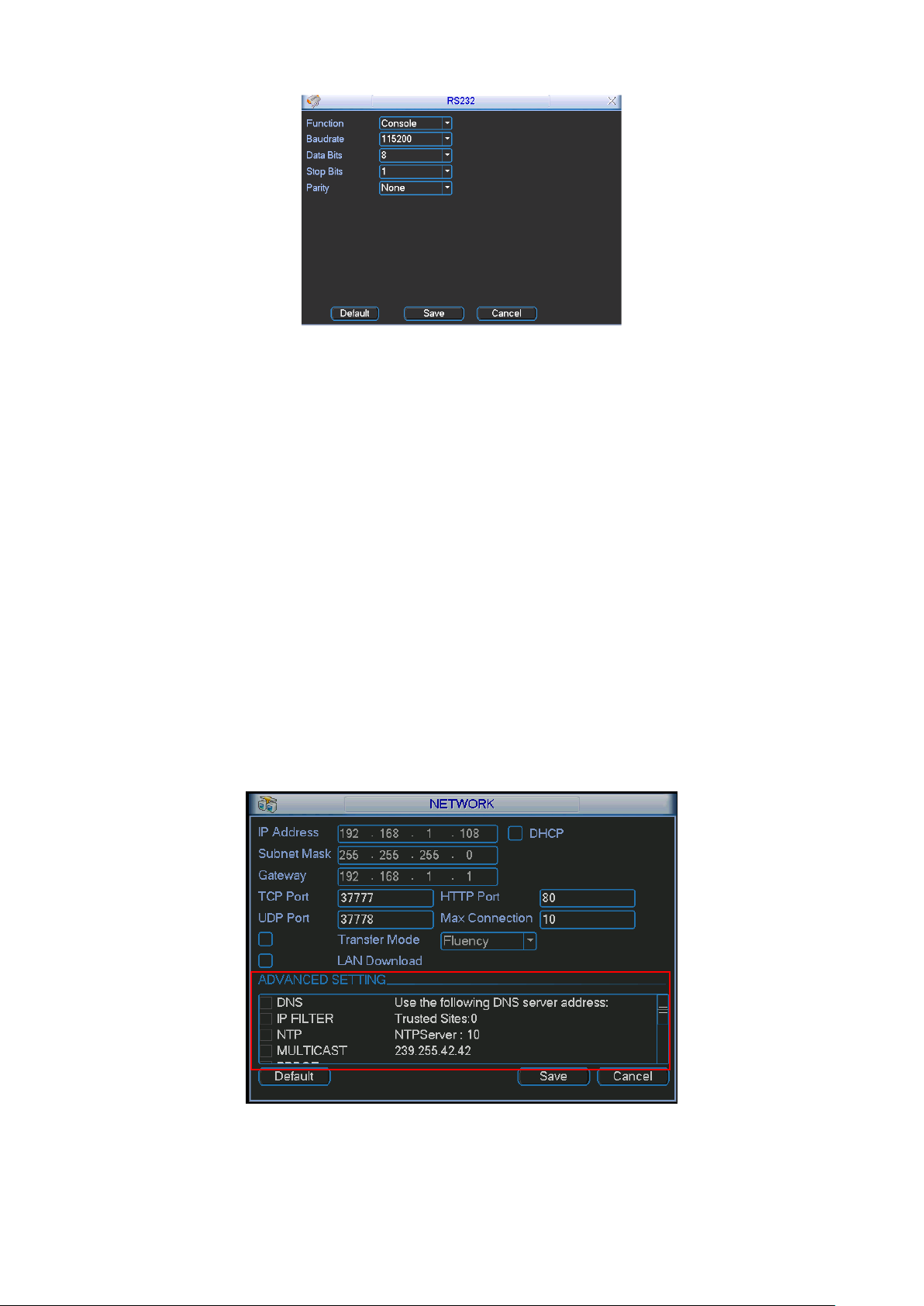
57
Figure 5-8
5.3.5 Network
Here is for you to input network information. See X364H364H364HFigure 5-9.X
IP address: Here you can input IP address.
DHCP: It is to auto search IP. When enable DHCP function, you can not modify IP/Subnet
mask /Gateway. These values are from DHCP function. If you have not enabled DHCP
function, IP/Subnet mask/Gateway display as zero. You need to disable DHCP function to
view current IP information. Besides, when PPPoE is operating, you can not modify
IP/Subnet mask /Gateway.
TCP port: Default value is 37777.
UDP port: Default value is 37778.
HTTP port: Default value is 80.
Max connection: system support maximal 10 users. 0 means there is no connection limit.
Transfer mode: Here you can select the priority between fluency/video qualities.
LAN download: System can process the downloaded data first if you enable this function.
The download speed is 1.5X or 2.0X of the normal speed.
After completing all the setups please click save button, system goes back to the previous menu.
Figure 5-9
5.3.5.1 Advanced Setup
Page 58

58
Advanced setup interface is shown as in X365H365H365HFigure 5-10X. Please draw a circle to enable
corresponding function and then double click current item to go to setup interface.
Figure 5-10
5.3.5.2 IP Filter
IP filter interface is shown as in X366H366H366HFigure 5-11X. You can add IP in the following list. The list
supports max 64 IP addresses.
Please note after you enabled this function, only the IP listed below can access current 22-inch
combo DVR.
If you disable this function, all IP addresses can access current 22-inch combo DVR.
Figure 5-11
5.3.5.3 Multiple Cast Setup
Multiple-cast setup interface is shown as in X367H367H367HFigure 5-12X.
Figure 5-12
Here you can set a multiple cast group. Please refer to the following sheet for detailed
information.
Page 59

59
IP multiple cast group address
-224.0.0.0-239.255.255.255
-―D‖ address space
The higher four-bit of the first byte=‖1110‖
Reserved local multiple cast group address
-224.0.0.0-224.0.0.255
-TTL=1 When sending out telegraph
-For example
224.0.0.1 All systems in the sub-net
224.0.0.2 All routers in the sub-net
224.0.0.4 DVMRP router
224.0.0.5 OSPF router
224.0.0.13 PIMv2 router
Administrative scoped addressees
-239.0.0.0-239.255.255.255
-Private address space
Like the single broadcast address of RFC1918
Can not be used in Internet transmission
Used for multiple cast broadcast in limited space.
Except the above mentioned addresses of special meaning, you can use other addresses. For
example:
Multiple cast IP: 235.8.8.36
Multiple cast PORT: 3666.
After you logged in the Web, the Web can automatically get multiple cast address and add it to
the multiple cast groups. You can enable real-time monitor function to view the view.
Please note multiple cast function is for special series only.
5.3.5.4 PPPoE
PPPoE interface is shown as in X368H368H368HFigure 5-13X.
Input ―PPPoE name‖ and ―PPPoE password‖ you get from your ISP (Internet service provider).
Click save button, you need to restart to activate your configuration.
After rebooting, 22-inch combo DVR will connect to internet automatically. The IP in the PPPoE
is the 22-inch combo DVR dynamic value. You can access this IP to visit the unit.
Figure 5-13
5.3.5.5 NTP Setup
You need to install SNTP server (Such as Absolute Time Server) in your PC first. In Windows XP
OS, you can use command ―net start w32time‖ to boot up NTP service.
Page 60
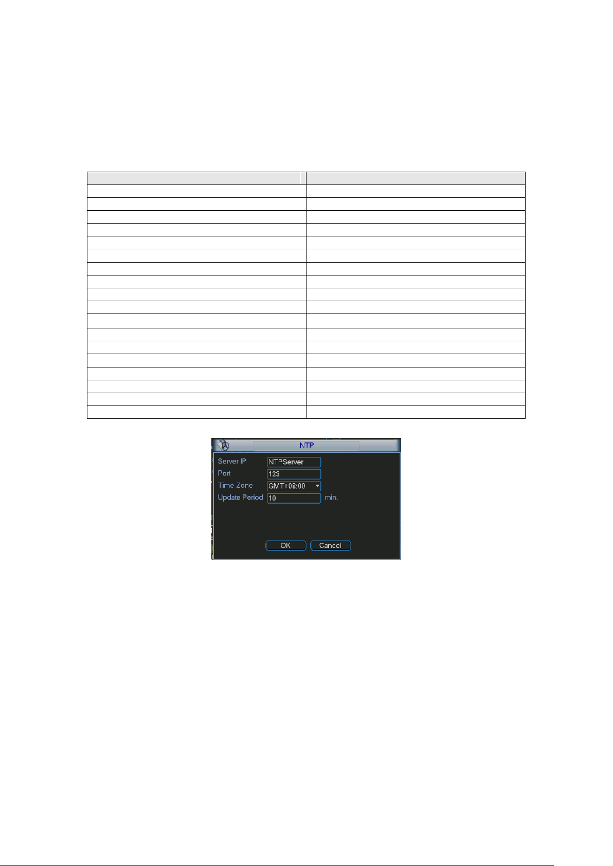
60
City /Region Name
Time Zone
London
GMT+0
Berlin
GMT+1
Cairo
GMT+2
Moscow
GMT+3
New Deli
GMT+5
Bangkok
GMT+7
Beijing (Hong Kong)
GMT+8
Tokyo
GMT+9
Sydney
GMT+10
Hawaii
GMT-10
Alaska
GMT-9
Pacific Time(P.T)
GMT-8
American Mountain Time(M.T)
GMT-7
American Central Time(C.T)
GMT-6
American Eastern Time(E.T)
GMT-5
Atlantic Time
GMT-4
Brazil
GMT-3
Middle Atlantic Time
GMT-2
NTP setup interface is shown as in X369H369H369HFigure 5-14X.
Host IP: Input your PC address.
Port: This series 22-inch combo DVR supports TCP transmission only. Port default value is
123.
Update interval: minimum value is 1. Max value is 65535. (Unit: minute)
Time zone: select your corresponding time zone here.
Here is a sheet for your time zone setup.
Figure 5-14
5.3.5.6 DDNS Setup
DDNS setup interface is shown as in X370H370H370HFigure 5-15X.
You need a PC to login the internet and then use the registered dynamic domain to access the
DVR.
In network DDNS, please select DDNS type and highlight enable item. Them please input your
PPPoE name you get from you IPS and server IP (PC with DDNS ) . Click save button and then
reboot system.
Click save button, system prompts for rebooting to get all setup activated.
After rebooting, open IE and input as below:
http://(DDNS server IP)/(virtual directory name)/webtest.htm
e.g.: http://10.6.2.85/ 22-inch combo DVR _DDNS/webtest.htm.)
Now you can open DDNSServer web search page.
Page 61

61
First, please enable
DHCP function here.
Then select
DNS item
here.
Figure 5-15
Please note NNDS type includes: CN99 DDNS, NO-IP DDNS, Private DDNS and Dyndns DDNS.
The Private DDNS works with special DDNS server and PSS software.
5.3.5.7 DNS
There are two modes: Manual setup and auto setup
Manual Setup
You can double click DNS to set DNS address manually. See Figure 5-16.
Please input preferred DNS server IP and alternative DNS server IP.
Figure 5-16
Auto gets DNS address
Please enable DHCP function first and then double click DNS item.
If the DHCP function enabled successfully, system can get the DNS server IP address. See
Figure 5-17.
Figure 5-17
Page 62

62
5.3.5.8 FTP
You need to download or buy FTP service tool (such as Ser-U FTP SERVER) to establish FTP
service.
Please install Ser-U FTP SERVER first. From ―start‖ -> ―program‖ -> Serv-U FTP Server -> ServU Administator. Now you can set user password and FTP folder. Please note you need to grant
write right to FTP upload user. See X372H372H372HFigure 5-18X.
Figure 5-18
You can use a PC or FTP login tool to test setup is right or not.
For example, you can login user ZHY to H140H140H140HTUFTP://10.10.7.7UTH and then test it can modify or delete
folder or not. See X373H373H373HFigure 5-19X.
Figure 5-19
System also supports upload multiple DVRs to one FTP server. You can create multiple folders
under this FTP.
In X374H374H374HFigure 5-9X, select FTP and then double click mouse. You can see the following interface.
See X375H375H375HFigure 5-20X.
Page 63
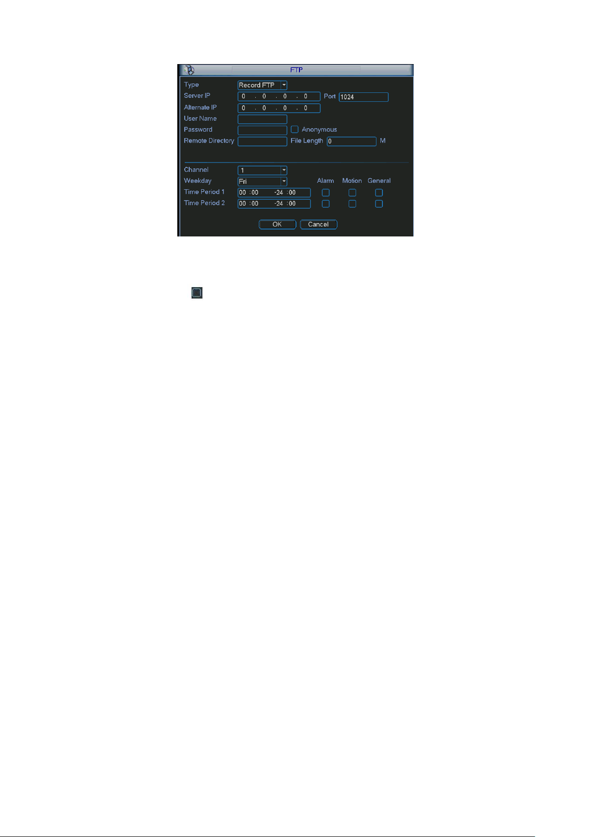
63
Figure 5-20
Please highlight the icon in front of Enable to activate FTP function.
Here you can input FTP server address, port and remote directory. When remote directory is null,
system automatically create folders according to the IP, time and channel.
User name and password is the account information for you to login the FTP.
File length is upload file length. When setup is larger than the actual file length, system will
upload the whole file. When setup here is smaller than the actual file length, system only uploads
the set length and auto ignore the left section. When interval value is 0, system uploads all
corresponding files.
After completed channel and weekday setup, you can set two periods for one each channel.
5.3.5.9 Email
The email interface is shown as below. See Figure 5-21.
SMTP server: Please input your email SMTP server IP here.
Port: Please input corresponding port value here.
User name: Please input the user name to login the sender email box.
Password: Please input the corresponding password here.
Sender: Please input sender email box here.
Title: Please input email subject here. System support English character and Arabic number.
Max 32-digit.
Receiver: Please input receiver email address here. System max supports 3 email boxes.
SSL enable: System supports SSL encryption box.
Interval: The send interval ranges from 0 to 3600 seconds. 0 means there is no interval.
Please note system will not send out the email immediately when the alarm occurs. When the
alarm, motion detection or the abnormity event activates the email, system sends out the email
according to the interval you specified here. This function is very useful when there are too many
emails activated by the abnormity events, which may result in heavy load for the email server.
Page 64

64
Figure 5-21
5.3.6 Alarm
Please refer to chapter 4.6 Alarm Setup and Activation.
5.3.7 Detect
Please refer to chapter 4.5 Detect.
5.3.8 Pan/Tilt/Zoom
The pan/tilt/zoom setup includes the following items. Please select channel first. See X376H376H376HFigure 5-
22.
Protocol: Select corresponding PTZ protocol such as PELCOD.
Address: input corresponding PTZ address.
Baud rate: Select baud rate.
Data bit: Select data bit.
Stop bit: Select stop bit.
Parity: There are three choices: none/odd/even.
After completed all the setups please click save button, system goes back to the previous menu.
For detailed setup, please refer to chapter 4.9 preset/patrol/pattern/scan.
Figure 5-22
Page 65

65
5.3.9 Display
Display setup interface is shown as below. See Figure 5-23.
Transparency: Here is for you to adjust transparency. The value ranges from 128 to 255.
Channel name: Here is for you to modify channel name. System max support 25-digit (The
value may vary due to different series). Please note all your modification here only applies to
22-inch combo DVR local end. You need to open web or client end to refresh channel name.
Time display: You can select to display time or not when system is playback.
Channel display: You can select to channel name or not when system is playback.
Resolution: The system supports 1355×768, 1280×1024, 1280×720(default), 1024×768,
800×600. Please note the device needs to reboot to activate current setup.
Display mode: you can select from the dropdown list.
Enable tour: Activate tour function.
Interval: Input proper interval value here. The value ranges from 5-120 seconds. In tour
process, you can use mouse or click Shift to turn on window switch function. Stands for
opening switch function, stands for closing switch function.
Motion tour type: System support 1/8 window tour.
Alarm tour type: System support 1/8 window tour.
Please highlight icon to select the corresponding function.
After completing all the setups please click save button, system goes back to the previous menu.
Figure 5-23
In X378H378H378HFigure 5-23, click modify button after channel. You can see an interface is shown as in
X379H379H379HFigure 5-24X. Please note all your modification here applies to local end only. You need to
refresh web or client-end to get the latest channel name. System max support 25-digital
character.
Page 66

66
Figure 5-24
In tour mode, you can see the following interface. On the right corner, right click mouse or click
shift button, you can control the tour. There are two icons: stands for enabling window switch
and stands for enabling window function. See Figure 5-25.
Figure 5-25
5.3.10 Default
Click default icon, system pops up a dialogue box. You can highlight to restore default factory
setup. See X381H381H381HFigure 5-26.
Select all
General
Encode
Schedule
RS232
Network
Alarm
Detect
Pan/tilt/zoom
Display
Channel name
Page 67

67
Please highlight icon to select the corresponding function.
After all the setups please click save button, system goes back to the previous menu.
Warning!
System menu color, language, time display mode, video format, IP address, user account will not
maintain previous setup after default operation!
Figure 5-26
5.4 Search
Please refer to chapter 4.3 Search.
5.5 Advanced
Double click advanced icon in the main window, the interface is shown as below. See X382H382H382HFigurer
5-27. There are total seven function keys: HDD management, alarm output, abnormity, manual
record, account, auto maintenance, and TV adjust.
Figure 5-27
5.5.1 HDD Management
Here is for you to view and implement hard disk management. See X383H383H383HFigure 5-28.
Page 68
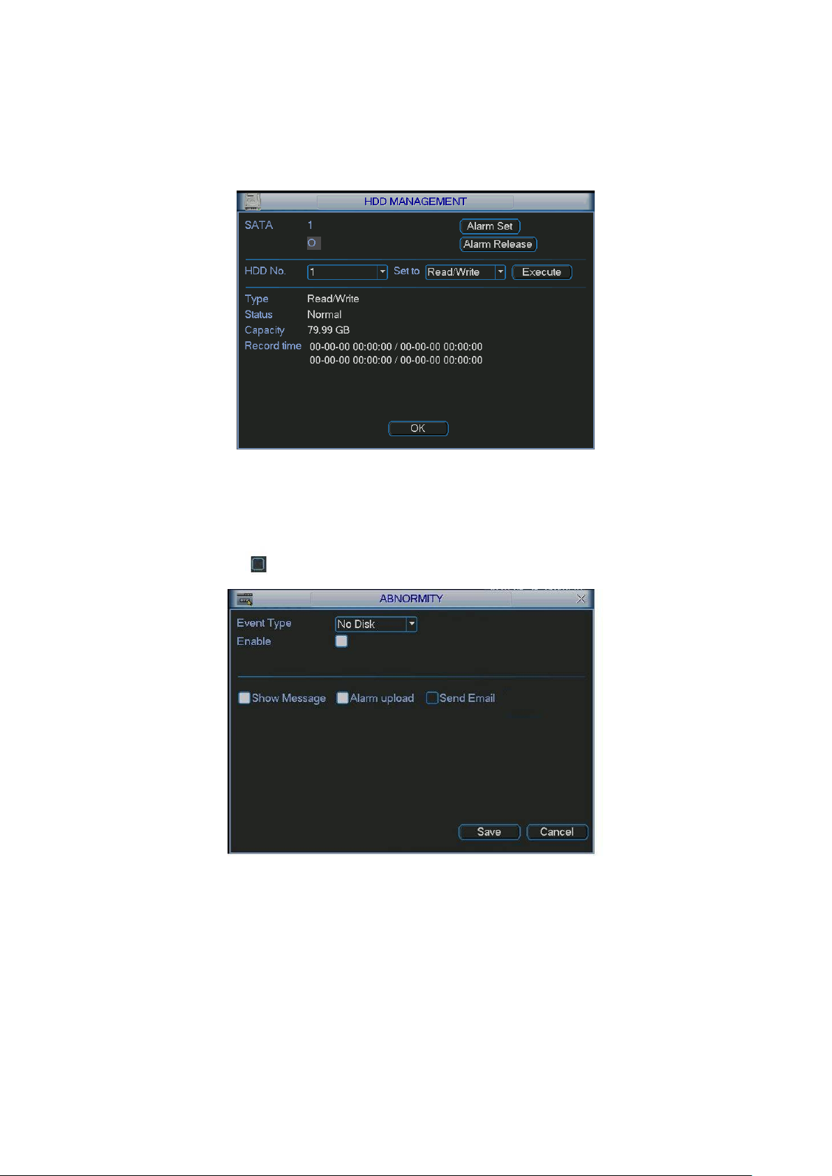
68
You can see current HDD type, status, capacity and record time. When HDD is working properly,
system is shown as O. When HDD error occurred, system is shown as X.
You can select HDD mode from the dropdown list such as read-only or you can erase all data in
the HDD.
Please note system needs to reboot to get all the modification activated.
Figure 5-28
Click alarm set button, the interface is shown as below. See X384H384H384HFigure 5-29 (This interface is just
like the abnormity setup). Please refer to chapter 5.5.2 for detailed information.
Please highlight icon to select the corresponding function.
Figure 5-29
5.5.2 Abnormity
Abnormity interface is shown as in X385H385H385HFigure 5-30.
Event type: There are several options for you such as disk error, no disk, disconnection,
IP conflict and etc.
Alarm output: Please select alarm activation output port.
Latch: Here you can set corresponding delaying time. The value ranges from 10s-300s.
System automatically delays specified seconds in turning off alarm and activated output after
external alarm cancelled.
Page 69
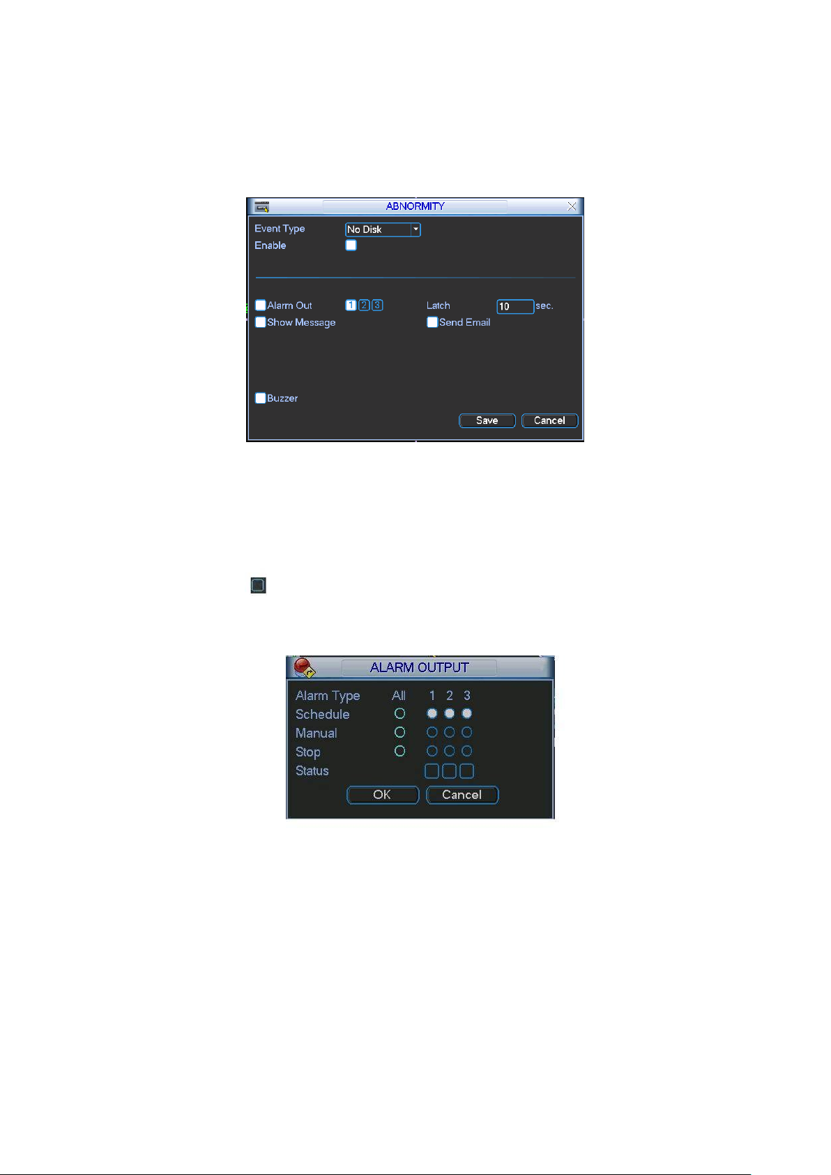
69
Show message: system can pop up the message in the local screen to alert you when
alarm occurs.
Alarm upload: System can upload the alarm signal to the network (including alarm centre)
if you enabled current function.
Send email: System can send out email to alert you when alarm occurs.
Figure 5-30
5.5.3 Alarm Output
Here is for you to set proper alarm output.
Please highlight icon to select the corresponding alarm output.
After all the setups please click OK button, system goes back to the previous menu. See Figure
5-31.
Figure 5-31
5.5.4 Manual Record
Please refer to chapter 4.2.2 manual record.
5.5.5 Account
Here is for you to implement account management. See X387H387H387HFigure 5-32X. Here you can:
Add new user
Modify user
Add group
Page 70

70
Modify group
Modify password.
For account management please note:
For the user account name and the user group, the string max length is 6-byte. The
backspace in front of or at the back of the string is invalid. There can be backspace in the
middle. The string includes the valid character, letter, number, underline, subtraction sign,
and dot.
System account adopts two-level management: group and user. No limit to group or user
amount.
For group or user management, there are two levels: admin and user.
The user name and group name can consist of eight bytes. One name can only be used
once. There are four default users: admin/888888/666666 and hidden user ―default‖. Except
user 6666, other users have administrator right.
Hidden user ―default‖ is for system interior use only and can not be deleted. When there is
no login user, hidden user ―default‖ automatically login. You can set some rights such as
monitor for this user so that you can view some channel view without login.
One user should belong to one group. User right can not exceed group right.
About reusable function: this function allows multiple users use the same account to login.
After all the setups please click save button, system goes back to the previous menu.
Figure 5-32
5.5.5.1 Modify Password
Click password button, the interface is shown as in Figure 5-33.
Here you can modify account password.
Please select the account from the dropdown list, input the old password and then input the new
password twice. Click the Save button to confirm current modification.
For the users of user account right, it can modify password of other users.
Page 71

71
Figure 5-33
5.5.5.2 Add/Modify Group
Click add group button, the interface is shown as below. See Figure 5-34.
Here you can input group name and then input some memo information if necessary.
There are total 60 rights such as control panel, shut down, real-time monitor, playback, record,
record file backup, PTZ, user account, system information view, alarm input/output setup, system
setup, log view, clear log, upgrade system, control device and etc.
The modify group interface is similar to the Figure 5-34.
Figure 5-34
5.5.5.3 Add/Modify User
Click add user button, the interface is shown as in Figure 5-35.
Please input the user name, password, select the group it belongs to from the dropdown list.
Then you can check the corresponding rights for current user.
For convenient user management, usually we recommend the general user right is lower than
the admin account.
The modify user interface is similar to Figure 5-35.
Page 72

72
Figure 5-35
5.5.6 Auto Maintain
Here you can set auto-reboot time and auto-delete old files setup. See X388H388H388HFigure 5-36.
You can select proper setup from dropdown list.
After all the setups please click save button, system goes back to the previous menu.
Figure 5-36
5.5.7 TV Adjust
Here is for you to adjust TV output setup. See X389H389H389HFigure 5-37.
Please drag slide bar to adjust each item.
After all the setups please click OK button, system goes back to the previous menu.
Figure 5-37
5.6 Information
Page 73

73
Here is for you to view system information. There are total five items: HDD (hard disk
information), BPS (data stream statistics), Log and version, and online user. See X390H390H390HFigure 5-38.
Figure 5-38
5.6.1 HDD Information
Here is to list hard disk type, total space, free space, video start time and status. See X391H391H391HFigure 5-
39.
○ means current HDD is normal. X means there is error. - means there is no HDD.
If disk is damaged, system shows as ―?‖. Please remove the broken hard disk before you add a
new one.
Once there is a hard disk confliction, please check hard disk time and system time is the same or
not. Please go to setting then general to modify system time. At last, reboot the system to solve
this problem.
After system booted up, if there is any confliction, system goes to HDD information interface
directly. Please note, system does not ask you to deal with it forcedly.
When HDD confliction occurs, you can check system time and HDD time are identical or not. If
they are not identical, please go to General (Chapter 5.3.1) to adjust system time or go to HDD
Management (Chapter 5.5.1) to format HDD and then reboot the 22-inch combo DVR.
Figure 5-39
Page 74
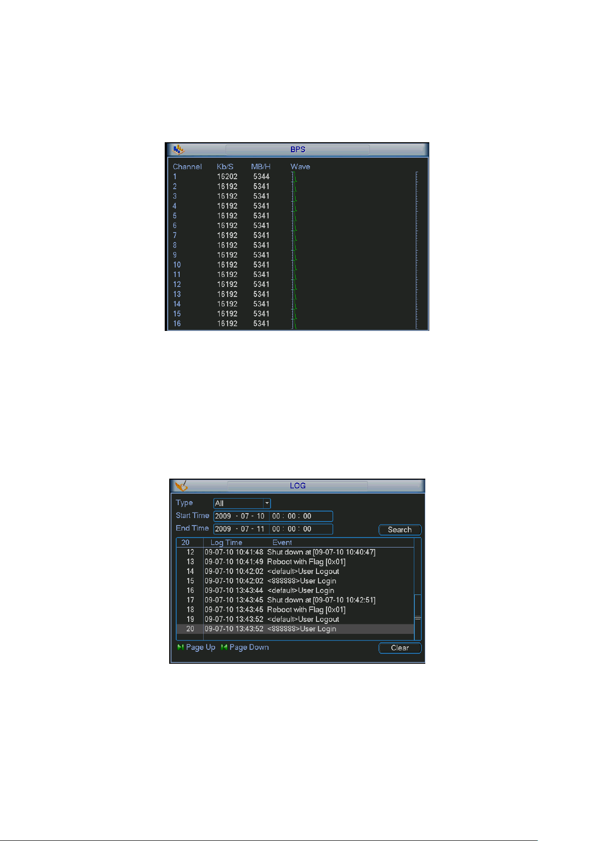
74
Tips:
Please click Fn button or left click mouse to view HDD record time and HDD type and time.
5.6.2 BPS
Here is for you to view current video data stream (KB/s) and occupied hard disk storage (MB/h).
See X392H392H392HFigure 5-40.
Figure 5-40
5.6.3 Log
Here is for you to view system log file. System lists the following information. See X393H393H393HFigure 5-41.
Log types include system operation, configuration operation, data management, alarm event,
record operation, log clear and etc.
Pleased select start time and end time, then click search button. You can view the log files.
Please page up/down button to view if there are more than ten files.
Figure 5-41
5.6.4 Version
Here is for you to view some version information. See X394H394H394HFigure 5-42.
Channel
Alarm in
Alarm out
Page 75

75
System version:
Build Date
Figure 5-42
5.6.5 Online Users
Here is for you manage online users. See X395H395H395HFigure 5-43.
You can disconnect one user or block one user if you have proper system right. Max
disconnection setup is 65535 seconds.
Figure 5-43
5.7 Shutdown
Double click shutdown button, system pops up a dialogue box for you to select. See Figure 5-44.
Logout menu user: log out menu. You need to input password when you login the next time.
Restart application: reboot 22-inch combo DVR.
Shutdown: system shuts down and turns off power.
Restart system: system begins rebooting.
Switch user: you can use another account to log in.
Page 76

76
Figure 5-44
Page 77
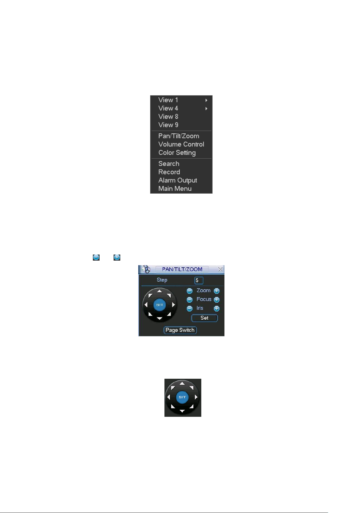
77
6 About Auxiliary Menu
6.1 Go to Pan/Tilt/Zoom Menu
In the one-window surveillance mode, right click mouse (click ―fn‖ Button in the front panel or
click AUX key in the remote control). The interface is shown as below: See X397H397H397HFigure 6-1X.
Figure 6-1
Click Pan/Tilt/Zoom, the interface is shown as in X398H398H398HFigure 6-2X.
Here you can set the following items:
Zoom
Focus
Iris
Please click icon and to adjust zoom, focus and Iris.
Figure 6-2
In X399H399H399HFigure 6-2X, please click direction arrows (See X400H400H400HFigure 6-3X ) to adjust PTZ position. There
are totally eight direction arrows. (Please note there are only four direction arrows in 22-inch
combo DVR front panel.)
Figure 6-3
6.1.1 3D Intelligent Positioning Key
In the middle of the eight direction arrows, there is a 3D intelligent positioning key. See X401H401H401HFigure
6-4X . Please make sure your protocol supports this function and you need to use mouse to
control.
Page 78
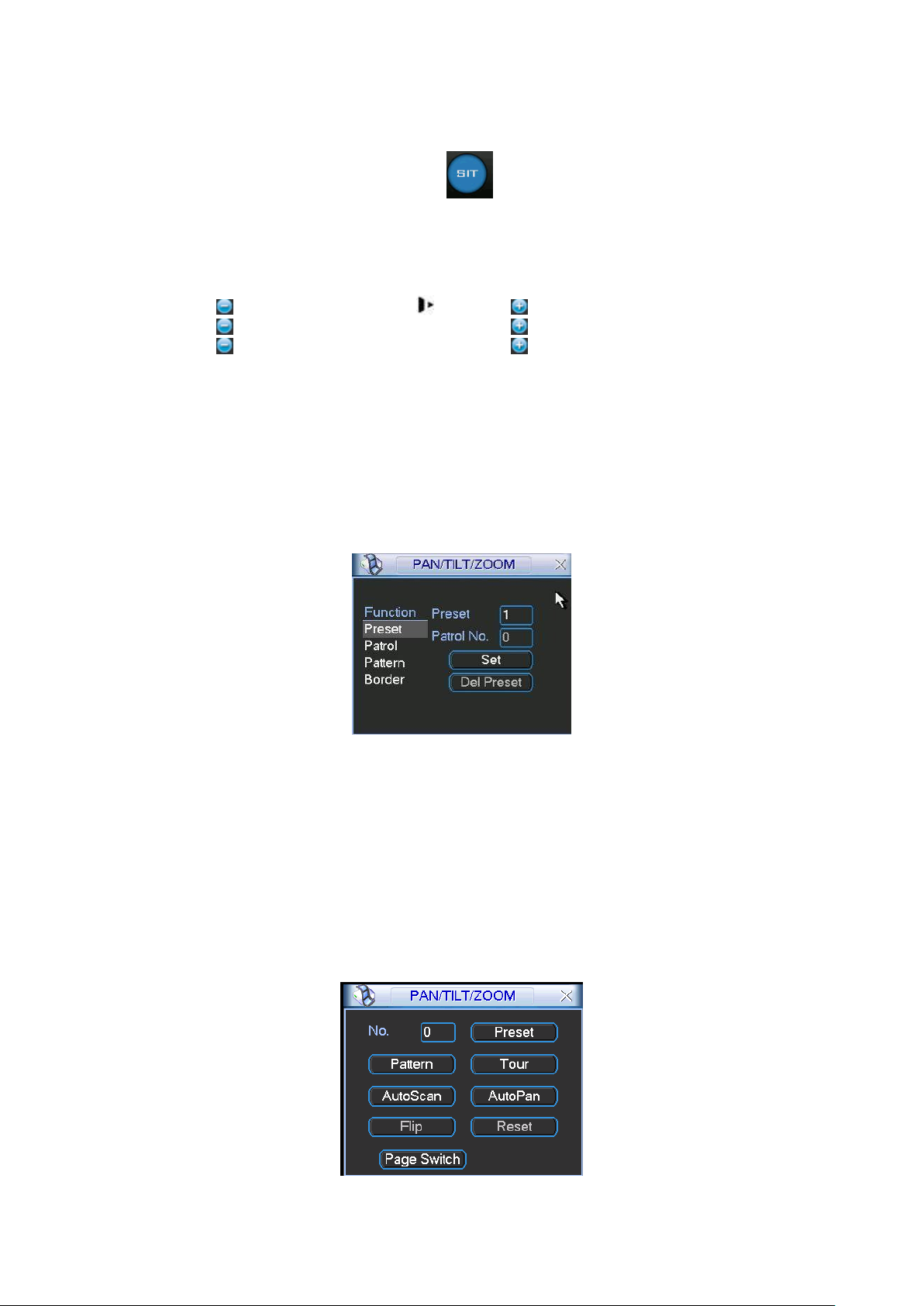
78
Name
Function
key
function
Shortcut
key
Function
key
function
Shortcut
key
Zoom
Near
Far
Focus
Near
│
Far
►│
Iris close
Open
Click this button, system goes back to the single screen mode. Drag the mouse in the screen to
adjust section size.
Figure 6-4
Here is a sheet for you reference.
6.2 Preset /Patrol / Pattern /Border Function
In X402H402H402HFigure 6-2X click the set button. The interface is shown as below:
Here you can set the following items:
Preset
Patrol
Pattern
Border
Figure 6-5
In X403H403H403HFigure 6-2X, click page switch button, you can see an interface as in X404H404H404HFigure 6-6X.
Here you can activate the following functions:
Preset
Tour(Patrol)
Pattern
Auto scan
Auto pan
Flip
Page Switch
Figure 6-6
Page 79
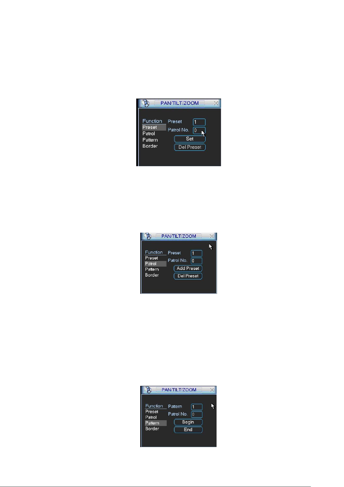
79
6.2.1 Preset Setup
Note: The following setups are usually operated in the X405H405H405HFigure 6-2X, X406H406H406HFigure 6-5X and X407H407H407HFigure
6-6X.
In X408H408H408HFigure 6-2X, use eight direction arrows to adjust camera to the proper position.
In X409H409H409HFigure 6-5X, click preset button and input preset number. The interface is shown as in X410H410H410HFigure
6-7X.
Add this preset to one patrol number
Figure 6-7
6.2.2 Activate Preset
In X411H411H411HFigure 6-6X please input preset number in the No. blank, and click preset button.
6.2.3 Patrol Setup
In X412H412H412HFigure 6-5X, click patrol button. The interface is shown as in X413H413H413HFigure 6-8X.
Input preset number and then add this preset to one patrol.
Figure 6-8
6.2.4 Activate Patrol
In X414H414H414HFigure 6-6X, input patrol number in the No. blank and click patrol button
6.2.5 Pattern Setup
In X415H415H415HFigure 6-5X, click pattern button and then click begin button. The interface shows like X416H416H416HFigure
6-9X.
Please go to X417H417H417HFigure 6-2X to modify zoom, focus, and iris. Go back to X418H418H418HFigure 6-9X and click end
button.
You can memorize all these setups as pattern 1.
Page 80

80
Figure 6-9
6.2.6 Activate Pattern Function
In X419H419H419HFigure 6-6X input mode value in the No. blank, and click pattern button.
6.2.7 Border Setup
In X420H420H420HFigure 6-5X, click border button. The interface is shown as in X421H421H421HFigure 6-10X.
Please go to X422H422H422HFigure 6-2X, use direction arrows to select camera left limit, and then please go to
X423H423H423HFigure 6-10X and click left limit button
Repeat the above procedures to set right limit.
Figure 6-10
6.2.8 Activate Border Function
In X424H424H424HFigure 6-6X, click auto scan button, the system begins auto scan. Correspondingly, the auto
scan button changes to stop button.
Click stop button to terminate scan operation.
6.2.9 Flip
In X425H425H425HFigure 6-6X, click page switch button, you can see an interface is shown as below. See
X426H426H426HFigure 6-11X. Here you can set auxiliary function.
Click page switch button again, system goes back to X427H427H427HFigure 6-2X.
Figure 6-11
Page 81

81
Input your IP
address here.
7 WEB OPERATION
There might be slightly difference in the interface due to different series.
The following operation is based on the 4-channel series product.
7.1 Network Connection
Before web operation, please check the following items:
Network connection is right
22-inch combo DVR and PC network setup is right. Please refer to network setup(main
menu->setting->network)
Use order ping ***.***.***.***(* 22-inch combo DVR IP address) to check connection is OK or
not. Usually the return TTL value should be less than 255.
Open the IE and then input 22-inch combo DVR IP address.
System can automatically download latest web control and the new version can overwrite
the previous one.
If you want to un-install the web control, please run uninstall webrec2.0.bat. Or you can go to
C:\Program Files\webrec to remove single folder. Please note, before you un-install, please
close all web pages, otherwise the un-installation might result in error.
7.2 Login
Open IE and input 22-inch combo DVR address in the address column. For example, if your 22inch combo DVR IP is 10.10.3.16, then please input http:// 10.10.3.16 in IE address column. See
X428H428H428HFigure 7-1X
Figure 7-1
System pops up warning information to ask you whether install webrec.cab control or not. Please
click yes button.
If you can’t download the ActiveX file, please modify your settings as follows. See X429H429H429HFigure 7-2X.
Page 82
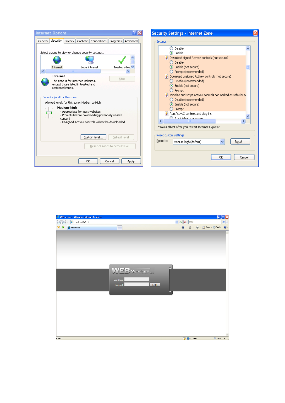
82
Figure 7-2
After installation, the interface is shown as below. See X430H430H430HFigure 7-3X.
Please input your user name and password.
Default factory name is admin and password is admin.
Note: For security reasons, please modify your password after you first login.
Figure 7-3
After you logged in, you can see the main window. See X431H431H431HFigure 7-6X.
This main window can be divided into the following sections.
Page 83

83
Section1
Section 2
Section 3
Section 5
Section 4
Section 1: there are five function buttons: configuration (chapter 7.3), search (chapter 7.4),
alarm (chapter 7.5), about (chapter 7.6), log out (chapter 7.7).
Section 2: there are channel number and three function buttons: start dialog and local play,
refresh.
Section3: there are PTZ (chapter 7.2.2), color (chapter 7.2.3) button and you can also select
picture path and record path.
Section 4:real-time monitor window. Please note current preview window is circled by a
green rectangle zone.
Section 5: Here you can view window switch button. You can also select video priority
between fluency or real-time.
System monitor window switch supports full screen/1-window/4-window/6-window/8-
window/9-window/13-window/16-window/20-window/25-window/36-window. See
X432H432H432HFigure 7-4X.
Figure 7-4
Preview window switch. System support 1/4/8/9/16-window real-time preview. Please you
need to have the proper rights to implement preview operation. You can not preview if you
have no right to preview the either channel. See Figure 7-5. Please note this series device
does not support this function.
Figure 7-5
Figure 7-6
7.2.1 Real-time Monitor
Page 84
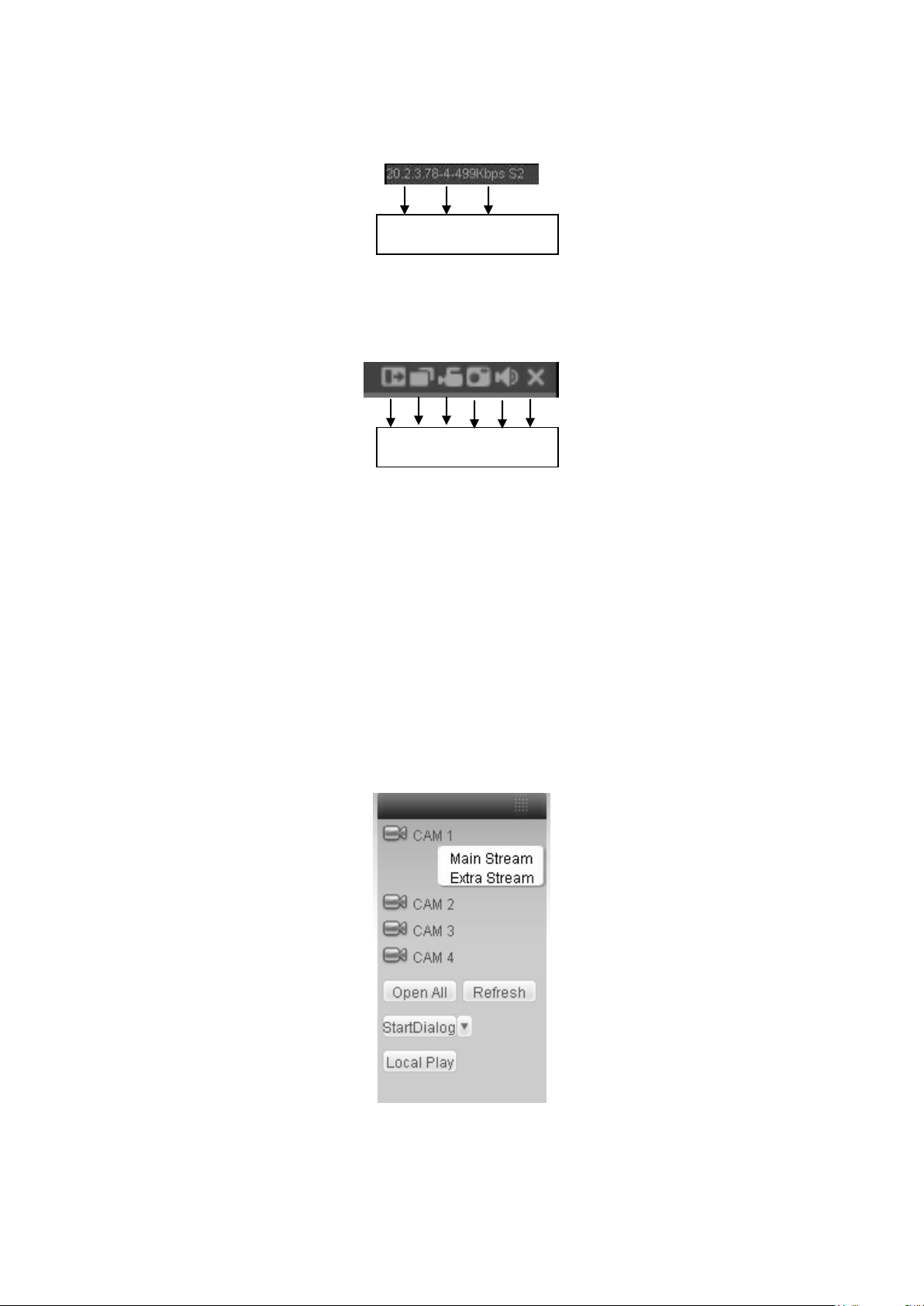
84
1 2 3 4 5 6
1 2 3
In section 2, left click the channel name you want to view, you can see the corresponding video
in current window.
On the top left corner, you can view device IP, channel number, network monitor bit stream.
Figure 7-7
On the top right corer, there are six unction buttons. See X434H434H434HFigure 7-8X.
Figure 7-8
1: Digital zoom: Click this button and then left drag the mouse in the zone to zoom in. right
click mouse system restores original status.
2: Change show mode: resize or switch to full screen mode.
3: Local record. When you click local record button, the system begins recording and this
button becomes highlighted. You can go to system folder RecordDownload to view the
recorded file.
4: Capture picture. You can snapshoot important video. All images are memorized in system
client folder \download\picture (default).
5: Audio :Turn on or off audio.(It has no relationship with system audio setup )
6: Close video.
Please refer to X435H435H435HFigure 7-9X for main stream and extra stream switch information.
Open All
You can click it to open all channels.
Figure 7-9
Page 85
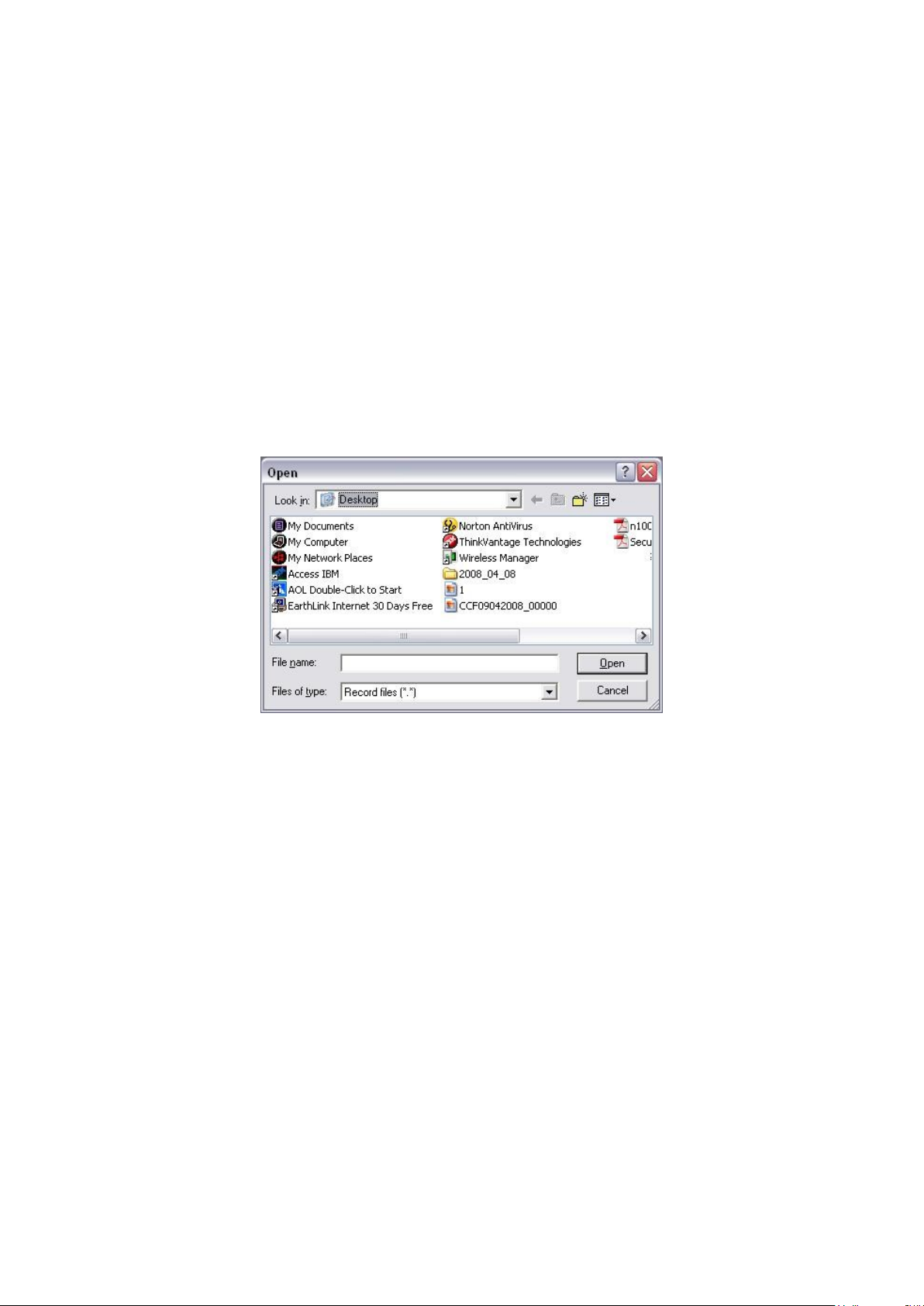
85
Refresh
You can use button to refresh camera list.
Start Dialogue
You can click this button to enable audio talk. Click 【▼】 to select bidirectional talk mode.
There are two options: DEFAULT/G711a.
Please note, the audio input port from the device to the client-end is using the first channel audio
input port. During the bidirectional talk process, system will not encode the audio data from the 1channel.
Local Play
The Web can playback the saved (Extension name is dav) files in the PC-end.
Click local play button, system pops up the following interface for you to select local play file. See
X436H436H436HFigure 7-10.X
Figure 7-10
7.2.2 PTZ
Before PTZ operation, please make sure you have properly set PTZ protocol. (Please refer to
chapter 7.3.2 Setting-> Pan/Tilt/Zoom).
Click PTZ button, the interface is shown as in X437H437H437HFigure 7-11X.
Page 86

86
Name
Function
key
Function
Function
key
Function
Zoom
Near
Far
Focus
Near
Far
Iris
close
Open
You can click this icon to
display or hide the PTZ
control platform.
3D Intelligent Positioning
Key
Figure 7-11
7.2.2.1 Direction key and 3D positioning key
In Figure 7-10, there are eight direction keys.
In the middle of the eight direction keys, there is a 3D intelligent positioning key.
Click 3D intelligent positioning key, system goes back to the single screen mode. Drag the
mouse in the screen to adjust section size. It can realize PTZ automatically.
7.2.2.2 Speed
System supports eight-level speed. You can select from the dropdown list. Speed 2 is faster than
speed 1.
7.2.2.3 Zoom/Focus/Iris
Here is a sheet for you reference.
In Figure 7-11, click PTZ setup button you can see the following interface. See X438H438H438HFigure 7-12X.
Page 87
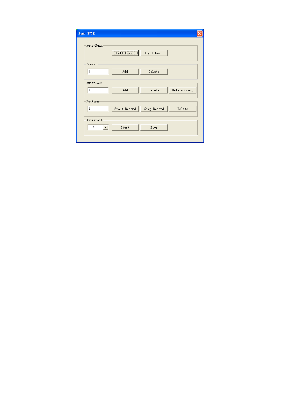
87
Figure 7-12
7.2.2.4 Auto Scan
In X439H439H439HFigure 7-12X, move the camera to you desired location and then click left limit button.
Then move the camera again and then click right limit button to set a right limit.
7.2.2.5 Pattern
In X440H440H440HFigure 7-12X, you can input pattern value and then click start record button to begin PTZ
movement. Please go back to Figure 7-11 to implement camera operation. Then you can click
stop record button. Now you have set one pattern.
7.2.2.6 Preset
In X441H441H441HFigure 7-12X, move the camera to your desired location and then input preset value. Click add
button, you have set one preset.
7.2.2.7 Auto tour
In X442H442H442HFigure 7-12X, input auto tour value and preset value. Click add button, you have added one
preset in the tour.
Repeat the above procedures you can add more presets in one tour.
7.2.2.8 Assistant
You can select the assistant item from the dropdown list. See X443H443H443HFigure 7-13X.
Page 88

88
Figure 7-13
7.2.3 Color
Click color button in section 3, the interface is shown as X444H444H444HFigure 7-14X.
Here you can select one channel and then adjust its brightness, contrast, hue and saturation.
(Current channel border becomes green).
Or you can click default button to use system default setup.
Figure 7-14
7.2.4 Picture Path and Record Path
Click more button in X445H445H445HFigure 7-14X, you can see an interface is shown as in X446H446H446HFigure 7-15X.
Figure 7-15
Click picture path button, you can see an interface is shown as in X447H447H447HFigure 7-16X.
Please click choose button to modify path.
Page 89

89
Figure 7-16
Click record path button, you can see an interface is shown as in X448H448H448HFigure 7-17X.
Please click choose button to modify path.
Figure 7-17
Click reboot button, system pops up the following dialogue box. See Figure 7-18,
Please click OK to reboot.
Figure 7-18
If there is local use logged in the system menu, or the Web logged in user has no right to reboot
the device system pops up a dialogue box to alert you.
7.3 Configure
7.3.1 System Information
7.3.1.1 Version Information
Here you can view device hardware feature and software version information. See X449H449H449HFigure 7-19X.
Page 90

90
Figure 7-19
7.3.1.2 HDD information
Here you can view local storage status and network status including, free capacity and total
capacity. See X450H450H450HFigure 7-20X.
Figure 7-20
7.3.1.3 Log
Here you can view system log. See X451H451H451HFigure 7-21X.
Page 91

91
Parameter
Function
Type
Log types include: system operation, configuration operation, data
management, alarm event, record operation, user management, log
clear and file operation.
Search
You can select log type from the drop down list and then click search
button to view the list.
Clear
You can click this button to delete all displayed log files. Please note
system does not support clear by type.
Backup
You can click this button to backup log files to current PC.
Figure 7-21
Click backup button, the interface is shown as in X452H452H452HFigure 7-22X.
Figure 7-22
Please refer to the following sheet for log parameter information.
7.3.2 System Configuration
Please click save button to save your current setup.
Page 92
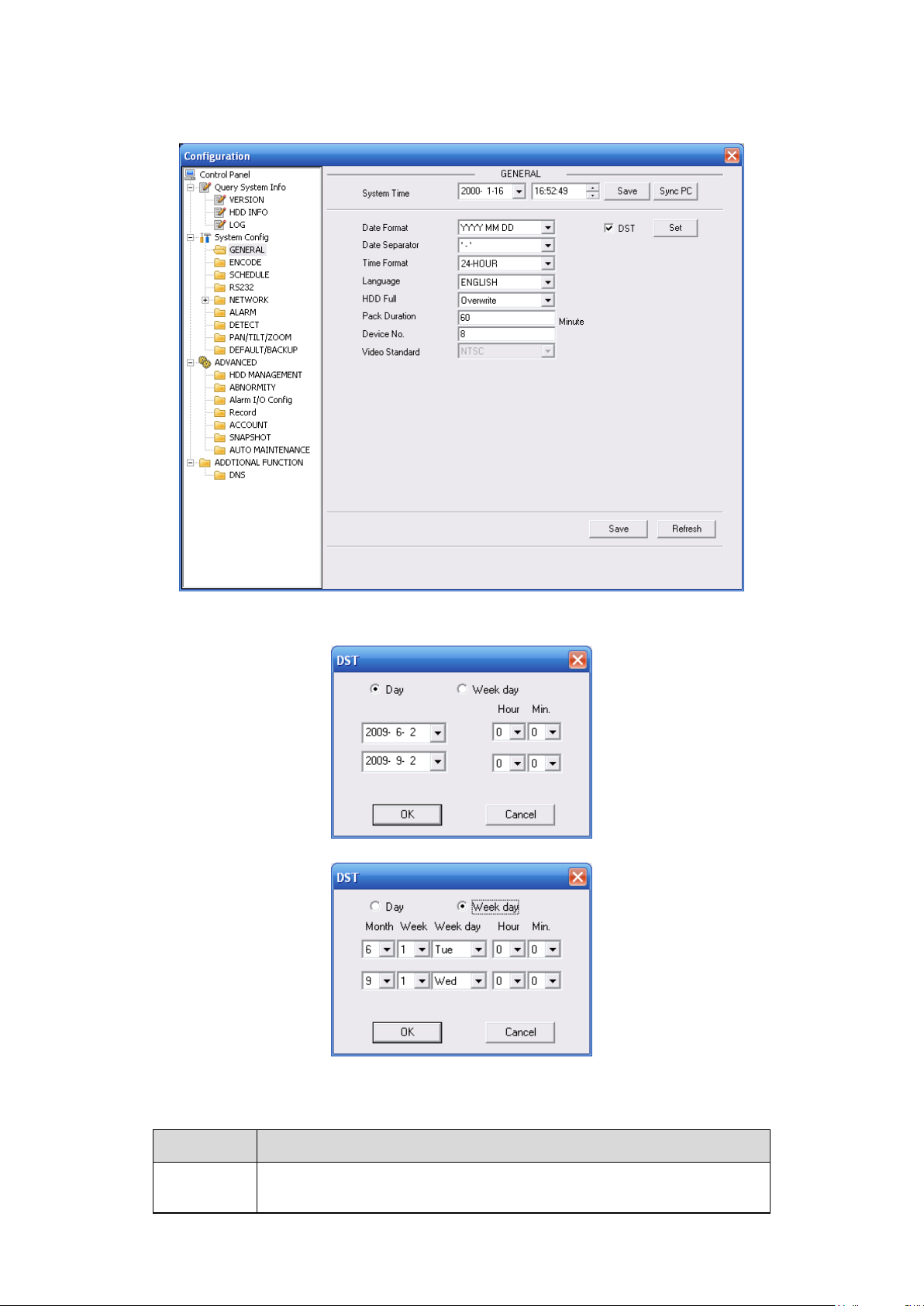
92
Parameter
Function
System
Time
Here is for you to modify system time. Please click Save button after
your completed modification
7.3.2.1 General Setup
Here you can set system time, record length, video format and etc. See X453H453H453HFigure 7-23X.
Figure 7-23
Figure 7-24
Figure 7-25
Please refer to the following sheet for detailed information.
Page 93

93
Sync PC
You can click this button to save the system time as your PC current
time.
Data
Format
Here you can select data format from the dropdown list.
Data
Separator
Please select separator such as – or /.
Time
Format
There are two options: 24-H and 12-H.
DST
Here you can set day night save time begin time and end time. See
Figure 7-24 and Figure 7-25.
Language
You can select the language from the dropdown list. Device needs to
reboot to get the modification activated.
HDD Full
There are two options: stop recording or overwrite the previous files
when HDD is full.
When current working HDD is overwriting or it is full now, system
stops record.
If current working HDD is full now, system goes to overwrite the
previous file.
Pack
Duration
Here you can select file size. The value ranges from 1 to 120.Default
setup is 60 minutes.
Device No
When you are using one remote control (not included in the
accessory bag) to manage multiple devices, you can give a serial
numbers to the device.
Please click the address button in the remote control and then input
the corresponding number to control the 22-inch combo DVR.
Video
Standard
There are two options: PAL/NTSC.
Please note, for the Web user, this information is for reference only.
You can not modify.
7.3.2.2 Encode
Encode interface is shown as in X454H454H454HFigure 7-26X.
Page 94

94
Parameter
Function
Channel
Here is for you to select a monitor channel.
Channel Name
Here is to display current channel name. You can modify it.
Compression
H.264
Main Stream
It includes main stream, motion stream and alarm stream. You can
select different encode frame rates form different recorded events.
For example, you can use high frame rate to record important events,
record scheduled event in lower frame rate and it allows you to set
different frame rates for motion detection record and alarm record.
Extra Stream
Select extra stream if you enabled the extension stream to monitor.
Audio/Video
For the main stream, recorded file only contains video by default. You
need to draw a circle here to enable audio function.
For extra stream, you need to draw a circle to select the video first and
then select the audio if necessary.
Figure 7-26
Figure 7-27
Please refer to the following sheet for detailed information.
Page 95

95
Parameter
Function
Resolution
Main stream resolution supports D1/CIF/QCIF.
Extra stream of channel 1 to channel 8 support QCIF only.
The different channels support different resolutions; the frame rate may
vary too.
Frame Rate
PAL:1~25f/s;NTSC:1~30f/s
For the 8-ch (16-ch) series 22-inch combo DVR:
If the 1-ch (or the 9-ch) resolution is D1 (PAL: 25f/s. NTSC: 30f/s),
the rest channels (2-8-ch or 10-16-ch) support CIF/QCIF.
If the 1-ch (or the 9-ch) resolution is D1 (PAL: ≤ 6/fs, NTSC: ≤7f/s),
the rest channels (2-8-chnanel or 10-16-channel) support D1
(PAL: ≤6f/s. NTSC: ≤7f/s)/CIF/QCIF.
Bit Rate Type
There are two options: VBR and CBR.
Please note, you can set video quality in VBR mode only.
Quality
The value ranges from 1 to 6. The level 6 is the best video quality.
Bit Rate
In CBR, the bit rate here is the max value. In dynamic video, system
needs to low frame rate or video quality to guarantee the value.
The value is null in VBR mode.
Please refer to recommend bit rate for the detailed information.
Recommended
Bit
Recommended bit rate value according to the resolution and frame
rate you have set.
Color Setting
Here you can set video brightness, contrast ness, hue, saturation and
gain.
The value ranges from 0 to 100.Default value is 50. See Figure 7-27.
Please note, some series devices do not support OSD transparent
setup function.
Cover area
(privacy mask)
Here you can privacy mask the specified video in the monitor video.
One channel max supports 4 privacy mask zones.
The privacy mask includes two options: Never/monitor. Never: It
means do not enable privacy mask function. Monitor: the privacy mask
zone can not be viewed in monitor mode.
Time Title
You can enable this function so that system overlays time information
in video window.
OSD transparent value ranges from 0 to 255. 0 means complete
transparent.
You can use the mouse to drag the time tile position.
Channel Title
You can enable this function so that system overlays channel
information in video window.
OSD transparent value ranges from 0 to 255. 0 means complete
transparent.
You can use the mouse to drag the channel tile position.
Copy
It is a shortcut menu button. You can copy current channel setup to
one or more channels. The interface is shown as in
X455H455H455HFigure 7-28X.
Save
You can click save button after you complete setup for one channel, or
you can complete the whole setups and then click save button.
Refresh
Click this button to get device latest configuration information.
Click copy interface, the interface is shown as in X456H456H456HFigure 7-28X.
If you have completed the setup for channel 1, you can click 3 to copy current setup to channel 3.
Or you can click 2, 3, and 4 to copy current setup to channel 2, channel 3 and channel 4.
Page 96
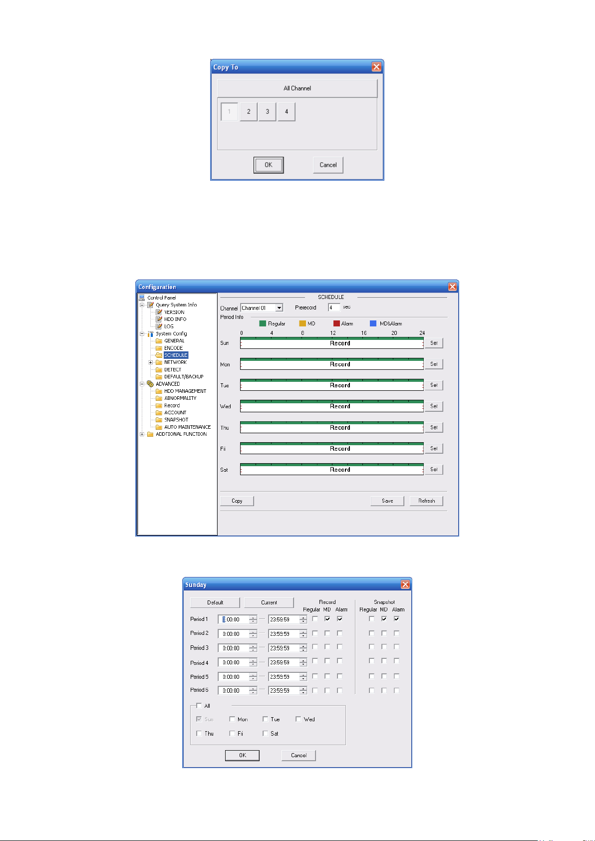
96
Figure 7-28
7.3.2.3 Schedule
Here you can set different periods for various days. There are max six periods in one day. See
X457H457H457HFigure 7-29X
Figure 7-29
Page 97
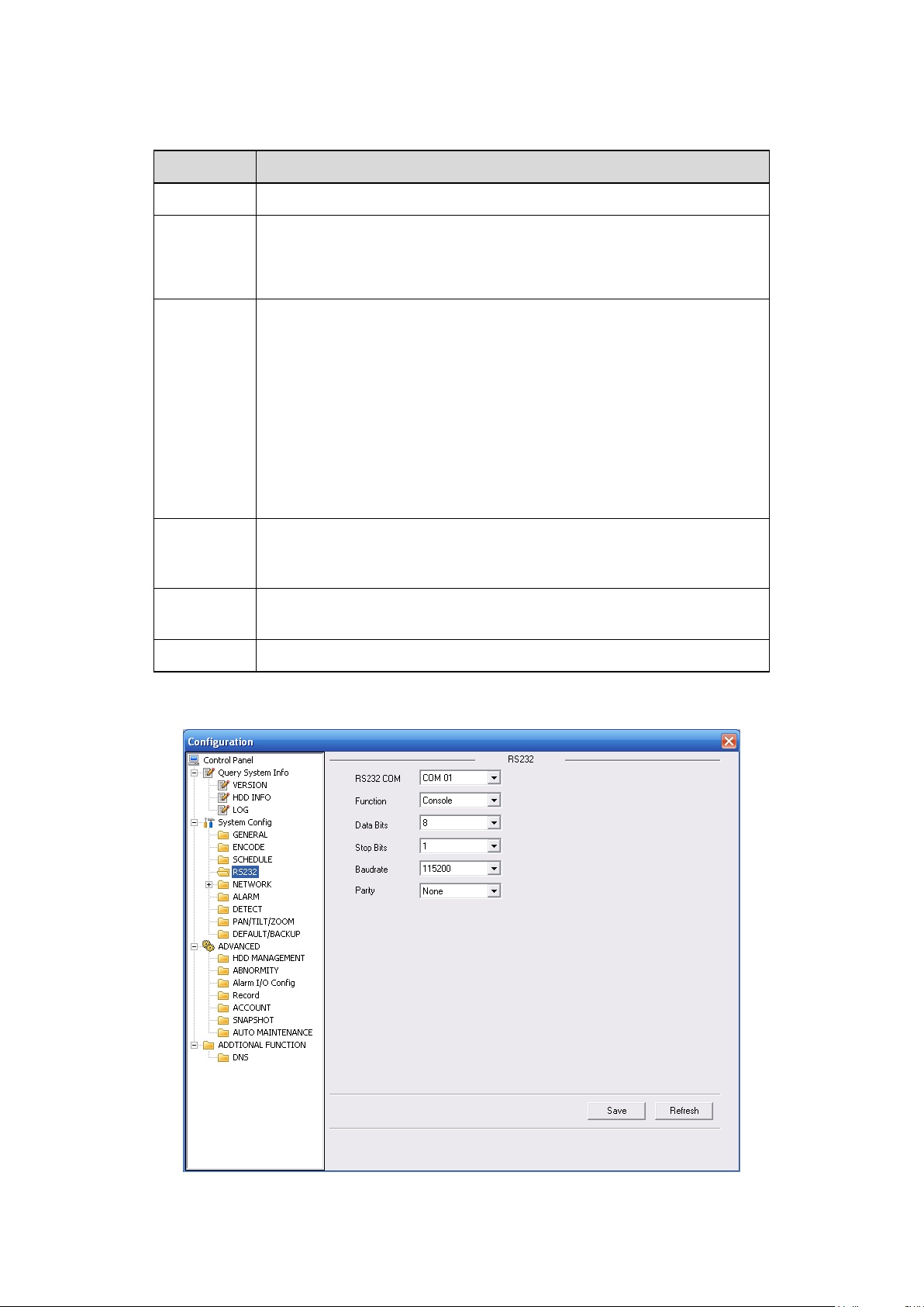
97
Parameter
Function
Channel
Please select a channel first.
Pre-record
Please input pre-record value here.
System can record the three to five seconds video before activating
the record operation into the file. (Depends on data size).
Setup
In X458H458H458HFigure 7-29X, click set button, you can go to the corresponding
setup interface.
Please set schedule period and then select corresponding record
or snapshot type: schedule/snapshot, motion detection/snapshot,
and alarm/snapshot.
Please select date (Current setup applies to current day by default.
You can draw a circle before the week to apply the setup to the
whole week.)
After complete setup, please go back to X459H459H459HFigure 7-29X and then
click save to save current time period setup.
Copy
It is a shortcut menu button. You can copy current channel setup to
one or more (all) channels. The interface is shown as in X460H460H460HFigure
7-28X.
Save
You can click save button after you complete setup for one channel,
or you can complete the whole setups and then click save button.
Refresh
Click this button to get device latest configuration information.
Figure 7-30
Please refer to the following sheet for detailed information.
7.3.2.4 RS232
The RS232 interface is shown as in X461H461H461HFigure 7-31X.
Figure 7-31
Page 98
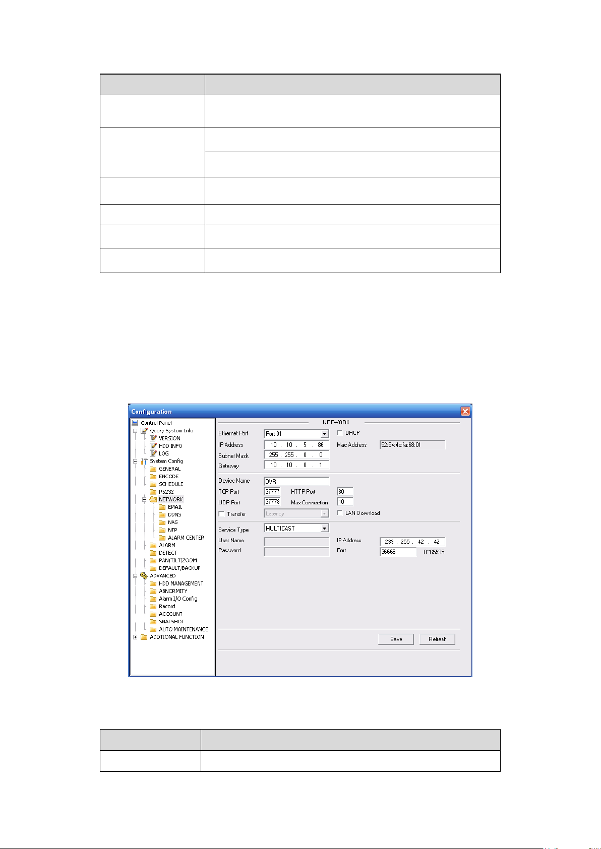
98
Parameter
Function
RS232
There are two options: COM 01 and keyboard.
Function
Console is to upgrade the program or debug via COM or
mini terminal software.
Keyboard: COM control protocol. You can use keyboard to
control 22-inch combo DVR via COM.
Data Bit
The value ranges from 5 to 8.
Stop Bit
There are two options: 1/2.
Baud Bit
You can select corresponding baud bit here.
Parity
There are five options: none/odd /even/mark/space.
Parameter
Function
Ethernet
Please select the network card first.
Please refer to the following sheet for detailed information.
System default setup is:
Function: Console.
Data bit: 8
Stop bit: 1
Baud bit: 115200
Parity: None.
7.3.2.5 Network
Network interface is shown as in X462H462H462HFigure 7-32X.
Please refer to the following sheet for detailed information.
Figure 7-32
Page 99
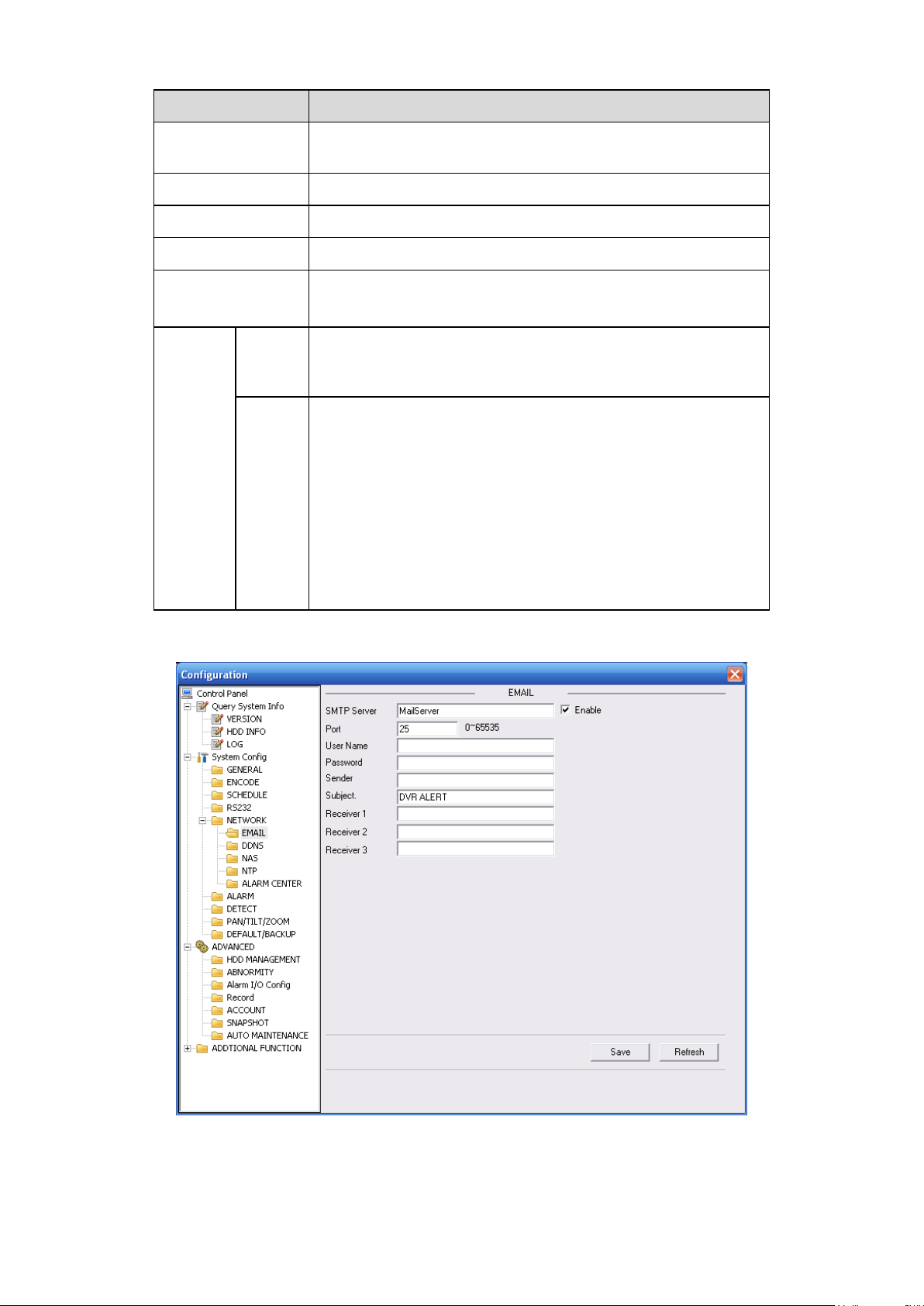
99
Parameter
Function
DHCP
Dynamically get IP address. You can get the device IP from
the DHCP server if you enabled this function.
TCP Port
Default value is 37777.
HTTP Port
Default value is 80.
UDP Port
Default value is 37778.
Max Connection
Network user max amount. The value ranges from 0 to 10.
O means there is no user can access current device.
Remote
Host
Multiple
cast
group
Set MULCAST address and port.
Enable MULCAST function.
PPPOE
Input the PPPoE user name and password you get from the
IPS (internet service provider) and enable PPPoE function.
Please save current setup and then reboot the device to
get the setup activated.
Device connects to the internet via PPPoE after reboot.
You can get the IP address in the WAN from the IP address
column.
Please note if you want to reboot the device please make
sure you have proper reboot right and there is no login user
in current device.
Email
The email interface is shown as in X463H463H463HFigure 7-33X.
Please refer to the following sheet for detailed information.
Figure 7-33
Page 100

100
Parameter
Function
SMTP Server
Input server address and then enable this function.
Port
Please input port value here..
User Name
The sender email account user name.
Password
The sender email account password.
Sender
Sender email address.
Subject
Input email subject here. Max 32-digit.
Address
Input receiver email address here. Max input three addresses.
Parameter
Function
Server Type
You can select DDNS protocol from the dropdown list and then
enable DDNS function. The private DDNS protocol means you
use your self-defined private protocol to realize DDNS function.
Server IP
DDNS server IP address
Server Port
DDNS server port.
Domain Name
Your self-defined domain name.
User
The user name you input to log in the server.
DDNS
The DDNS interface is shown as in X464H464H464HFigure 7-34X.
Please make sure your 22-inch combo DVR supports this function.
Figure 7-34
Please refer to the following sheet for detailed information.
 Loading...