

Page 1
English
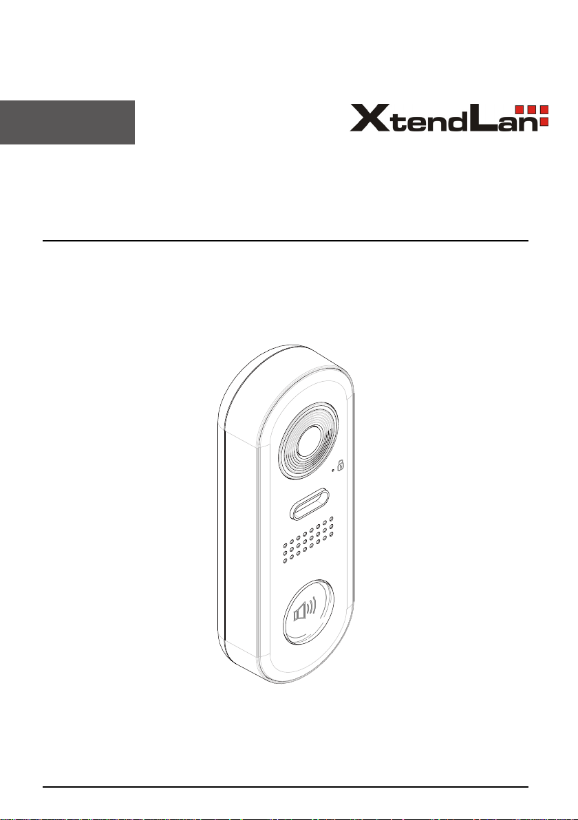
IP Video Outdoor Station
DPC-IP610
User Manual
Page 2
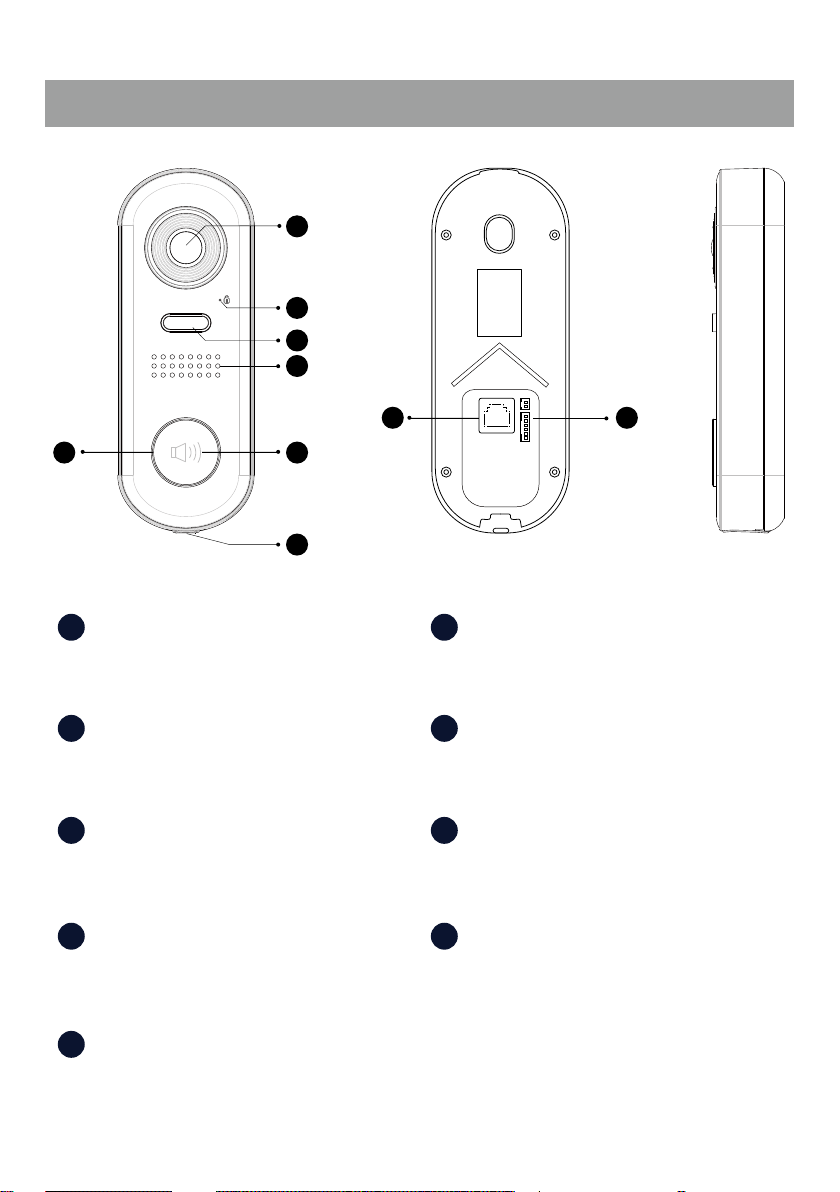
1.Parts and Functions
1
2
3
4
8 9
6
1 6
Camera Lens LED_KEY
5
7
Indicates monitoring,calling,unlock status.
+
12V
LKLK+
NO
EBEB+
2 7
LED_LOCK
Microphone
Indicates unlock status.
3 8
LED_CAM
Indicates monitoring status.
4 9
Speaker Terminal connector
Lan connector
Use to connect the door station to the network.
Use to connect external devices to the
door station
5
Call button
Press to call the indoot station(residerent).
-1-
Page 3
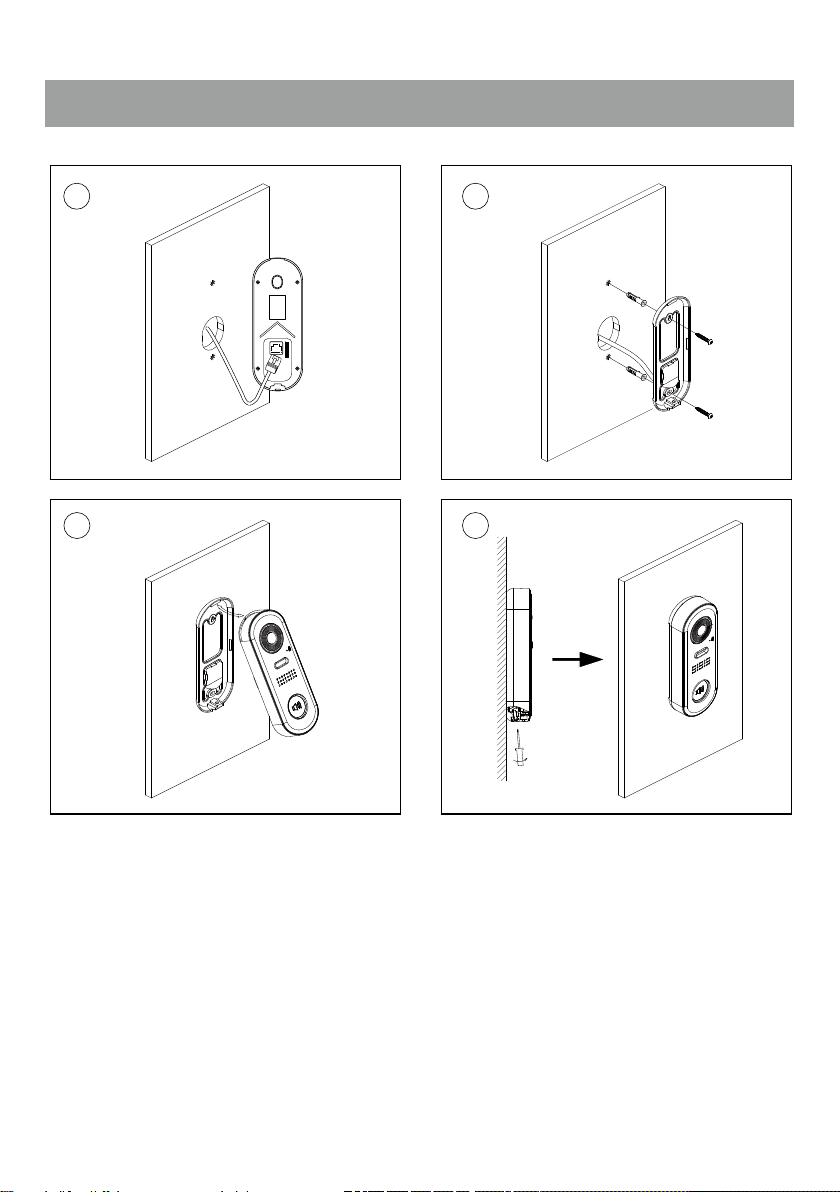
2.Mounting
1 2
+
12V
LKLK+
NO
EBEB+
43
1. Installation height for door station usually is 145~160cm.
2. Use screws to x the back panel to the wall after connect the cable correctly.
3. Attach the front panel to the back panel, then use the screw to x it.
-2-
Page 4
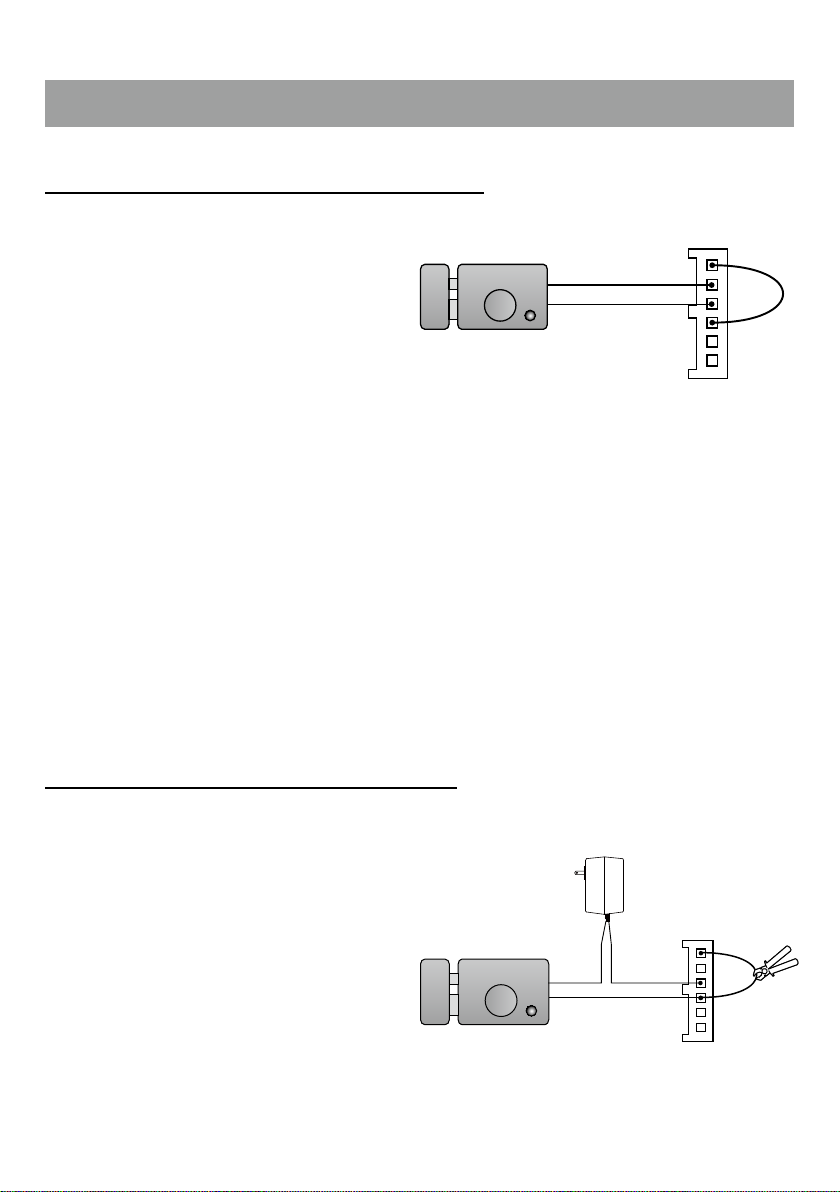
3.Electric Lock Connection
Door Lock Controlled with Internal Power
Note:
1. This mode only supports electromagnetic
locks.
2. Electromagnetic lock of Power-off-to-unlock
type should be used.
3. The door lock is limited to 12V, and holding
current must be less than 250mA.
4. The Unlock Mode Parameter of Monitor
must be set to 1 (by default).
12V 300mA
set to Normally open on the
Unlock Relay mode
-
+
12V
LK LK+
N.O.
EB EB +
Door Lock Controlled with Dry Contact
Note:
1. The external power supply must be used
according to the lock.
2. The inside relay contact is restricted to AC or
DC 24V/1A.
3. Setup the Unlock Mode of Monitor for
different lock types.
• Power-on-to-unlock type:Unlock Mode=0
(by default)
• Power-off-to-unlock type:Unlock Mode=1
set to Normally Open on the Unlock Relay mode (default)
-3-
-
+
+
-
+12V
LK LK+
N.O.
EBEB+
Page 5

4.Door station operations
Call button bind in Villa
Connect all devices and power on:
On indoor station(IX471)
1. From the main menu, tap "Setting" icon.
2. Select "Ext.Unit", and then tap "Auto setup wizard" item.
Door statin will be rename and call button will be binded to this monitor
Call button bind in Appartment
Connect all devices and power on:
On indoor station(IX471)
1. From the main menu, tap "Setting" icon.
2. Select "Ext.Unit", and then tap "Enter OS binding" item.
On door station
1. Power on the door station.
2. Press and hold the call button 10s.
-LED_CAM will ash once in the 5th second, and ash again in the 10th second.
3. The binding is successful.
Calling a residerent
Press the Call button to call.
Status check
Press and hold the Call button 5s.
-LED_CAM will ash once.
The status prompts are as follows:
-4-
Page 6

LEDs
Status
SIP registered ok Fast ashing
SIP registered error Normal ashing
SIP disabled/Not connected o
My master IM found Fast ashing
LED_LOCK LED_KEY
Other IX devices online,but master
oine
No other IX device detected o
Normal ashing
5. Specications
● Power Source : Power-over-Ethernet (IEEE 802.3af Class 0)
● LAN Interface : 10 BASE-T / 100 BASE-TX Ethernet (RJ-45)
● Camera: Type 1/3.7" Ultra Sense, ISP with 77dB WDR
● Len angle: 170 degree with Fisheye correction
● Minimum illumination: 5 lux
● Wire Type: Cat-5e or Cat-6
● Wiring Distance : 100m (Approx. 330')
● Operating temperature: -10 to +50 (oC)
● Protection: IP65;
● Dimension: 160(H)×60(W)×31.5(D)mm
-5-
Page 7
6. Precautions
• Please clean the unit with soft cotton cloth, don't use the organic impregnant or chemical clean agent. If
necessary, please use a little pure water or dilute soap water to clean the dust.
• The unit is weather resistant. However do not spray high pressure water on access control keypad directly.
Excessive moisture may cause problems with the unit.
• You must use the right adaptor which is supplied by the manufacture or approved by the manufacture..
• Pay attention to the high voltage inside the products, please refer service only to a trained and qualified
professional.
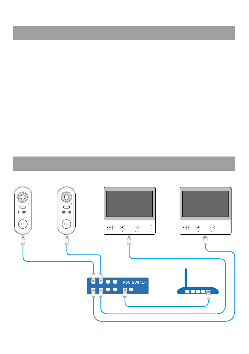
7. Single family wiring
-6-
Page 8

The design and specications can be modied without notice to the user. Right to interpret
and copyright of this manual are reserved.
 Loading...