

Page 1
Page 2
DeltaDirect Quick Start Guide Page 2
DeltaDirect – Quick Start Guide
Configuration of the Remote Interface on DPA Amplifiers
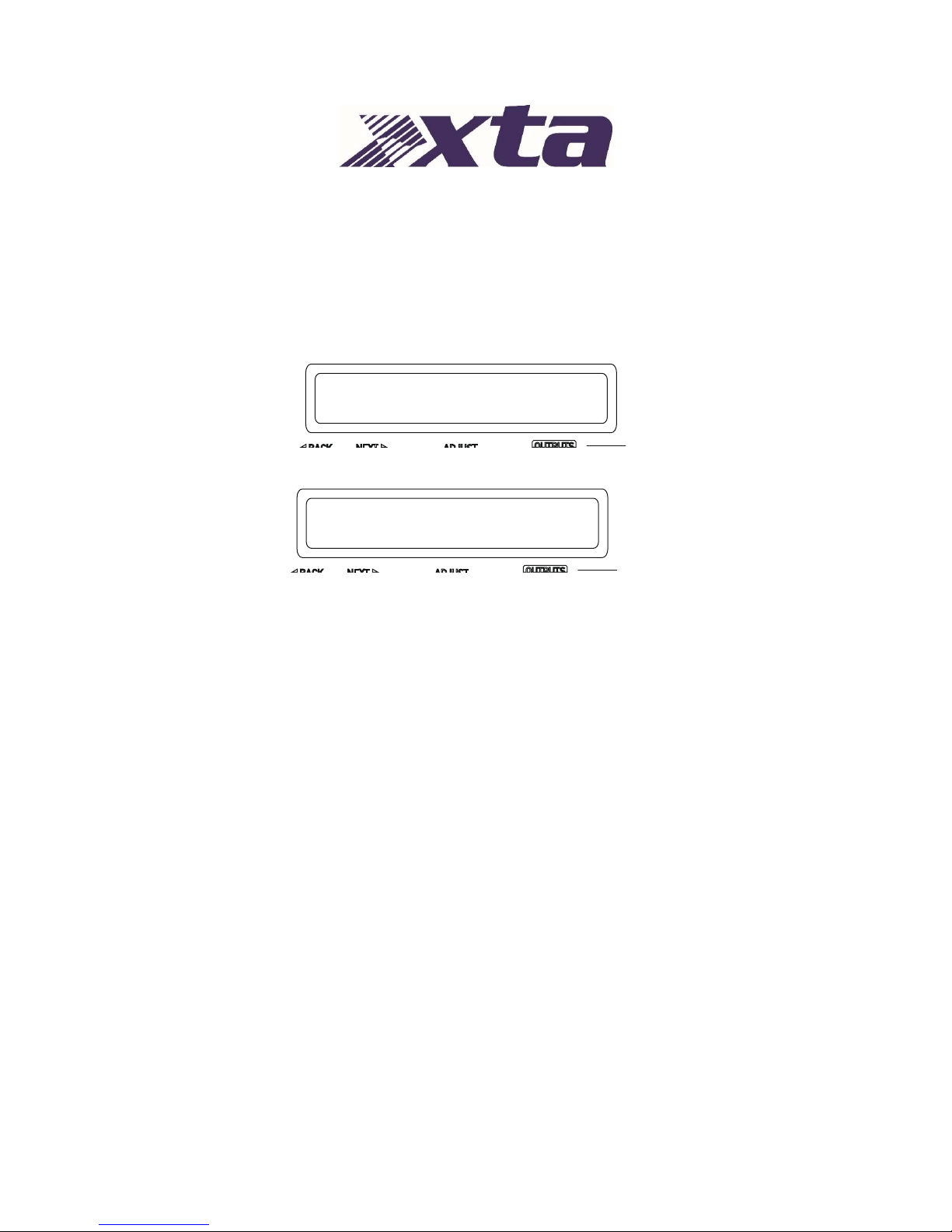
To configure the remote interface, from the home screen, press MENU, choose the INTERFACE SubMenu and press ENTER.
Use the encoder or BACK and NEXT keys to select External Interface and press ENTER.
Use the encoder or BACK and NEXT keys to choose the required interface and press ENTER.
For the purposes of working with the DeltaDirect app, the interface should be set to “Ethernet Only”.
This will invoke a series of further options depending on the interface chosen — these are explained
below:
Mode = Ethernet Only: The Ethernet control port on the rear panel is active. Selecting this
choice will then ask for the following further information to be confirmed:
RS485 Relay: Set to OFF.
Remote ID Number: Set a device ID (still required even on Ethernet connections).
This must be unique to the connected unit — setting the same ID on multiple units may cause
comms problems for all devices.
IP Mode: Choose either Static or Auto IP. Auto IP will generate an IP address based on
unique hardware features such as MAC address. Choose Static if you need to select the IP
address to lie within a specific range, for instance when working within a larger
infrastructure.
GtWay: The gateway address is used for external access to the Internet and should be
left at the default setting.
SubNt: The subnet mask is used to subdivide IP addresses into groups that allow further
sub-groups addressing to be defined, so further extending the address range.
Leave at default 255.255.255.0 unless specifically required.
IP: The IP address specifies the amplifier’s unique identifier on the Ethernet network. It is
used in conjunction with the amplifier’s Remote ID number to identify individual devices on
the network. Make sure this is not set to the same value as any other devices or comms
problems will occur.
INTERFACE Sub-Menu
External Interface
External Interface
Mode= Ethernet or USB
Page 3
DeltaDirect Quick Start Guide Page 3
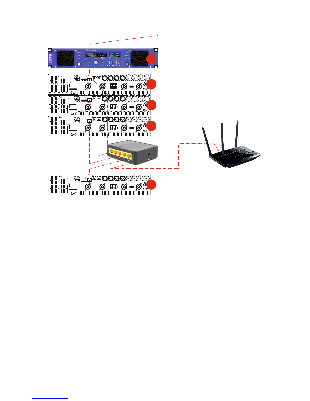
DeltaDirect connects to your WiFi network and to your DPA amplifiers via a wireless router. All
amplifiers must be connected via their Ethernet control port to the router, and we recommend that
there is a DHCP Server on the system to issue IP addresses automatically (this is normally the case
and most routers have this feature built-in - Ethernet switches may not so check the specs!)
All vents on front and r ear of unit m ust not be obstr ucted.
Tous les passages sur avant et arrière de l'unité ne doivent pas être obstrués.
SERIAL NO.
CH. D
OUT
CH. C
OUT
CH. B
OUT
CH. A
OUT
Class 3 Wiring
on Outputs
BRG
OUTPUT
CONNECTIONS
1+
1-
2+
2-
D+ C+ B+ A+
D- C- B- A-
D-B+B-
DCBA
D+
1 - AUDIO NETWORK - 2CONTROLGPIO PORT
123456
AUX 4 AUX 3 AUX 2 AUX 1
1: 0V
2/3: IN 1&2
4/5: OUT 1&2
6: +5V
RS485
DESIGNED AND
MANUFA CT UR ED
IN ENGLAND BY
SERIES
A
E
S
A
&
B
A
E
S
C
&
D
All vents on front and r ear of unit m ust not be obstr ucted.
Tous les passages sur avant et arrière de l'unité ne doivent pas être obstrués.
SERIAL NO.
CH. D
OUT
CH. C
OUT
CH. B
OUT
CH. A
OUT
Class 3 Wiring
on Outputs
BRG
OUTPUT
CONNECTIONS
1+
1-
2+
2-
D+ C+ B+ A+
D- C- B- A-
D-B+B-
DCBA
D+
1 - AUDIO NETWORK - 2CONTROLGPIO PORT
123456
AUX 4 AUX 3 AUX 2 AUX 1
1: 0V
2/3: IN 1&2
4/5: OUT 1&2
6: +5V
RS485
DESIGNED AND
MANUFA CT UR ED
IN ENGLAND BY
SERIES
A
E
S
A
&
B
A
E
S
C
&
D
All vents on front and r ear of unit m ust not be obstr ucted.
Tous les passages sur avant et arrière de l'unité ne doivent pas être obstrués.
SERIAL NO.
CH. D
OUT
CH. C
OUT
CH. B
OUT
CH. A
OUT
Class 3 Wiring
on Outputs
BRG
OUTPUT
CONNECTIONS
1+
1-
2+
2-
D+ C+ B+ A+
D- C- B- A-
D-B+B-
DCBA
D+
1 - AUDIO NETWORK - 2CONTROLGPIO PORT
123456
AUX 4 AUX 3 AUX 2 AUX 1
1: 0V
2/3: IN 1&2
4/5: OUT 1&2
6: +5V
RS485
DESIGNED AND
MANUFA CT UR ED
IN ENGLAND BY
SERIES
A
E
S
A
&
B
A
E
S
C
&
D
Ethernet t o P
C
Conn ect to all un its with s tandard
CAT5 Ethernet cable to router.
This unit’s interface set as:
Mode: Ethernet Only
RS485 Relay: Off
Remote ID Number: 1
IP Mode: Auto IP
Rear of First Unit
“Contro l” Port to Router w ith
CAT5 Ethernet Cable
Rear of Next Unit
“Contro l” Port to Router w ith
CAT5 Ethernet Cable
This unit’s interface set as for #1
EXCEPT
Remote ID Number: 2
All vents on front and r ear of unit m ust not be obstr ucted.
Tous les passages sur avant et arrière de l'unité ne doivent pas être obstrués.
SERIAL NO.
CH. D
OUT
CH. C
OUT
CH. B
OUT
CH. A
OUT
Class 3 Wiring
on Outputs
BRG
OUTPUT
CONNECTIONS
1+
1-
2+
2-
D+ C+ B+ A+
D- C- B- A-
D-B+B-
DCBA
D+
1 - AUDIO NETWORK - 2CONTROLGPIO PORT
123456
AUX 4 AUX 3 AUX 2 AUX 1
1: 0V
2/3: IN 1&2
4/5: OUT 1&2
6: +5V
RS485
DESIGNED AND
MANUFA CT UR ED
IN ENGLAND BY
SERIES
A
E
S
A
&
B
A
E
S
C
&
D
Rear of Next Unit
“Contro l” Port to Router w ith
CAT5 Ethernet Cable
This unit’s interface set as for #1
EXCEPT
Remote ID Number: 3
Rear of Last Unit
“Contro l” Port to Router w ith
CAT5 Ethernet Cable
This unit’s interface set as for #1
EXCEPT
Remote ID Number: N
#1
#1
#2
#3
#N
Wireless Router
Conn ect this to the other route r to go wireles s,
or connect all units direct to this router in place of the wired on
e
if it has enough ports.
Make sure DHCP Server function is not enabled in
both the standard a nd wireles s routers (if connecti ng like
this).
Page 4
DeltaDirect Quick Start Guide Page 4
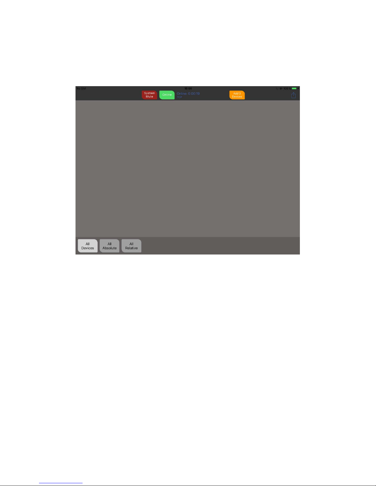
Going On-Line and Initialising…
Once the app is opened and on-line (pressing the on-line button does this!) the amplifiers will be
sending out identity messages and the app will recognise these and inform that an amp (or a number
of amps) are available to connect. Press the orange button that appears to start the process.
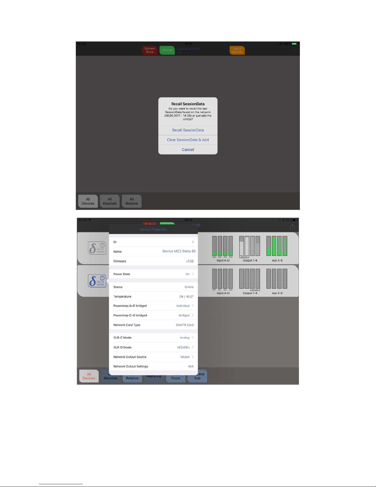
If grouping has been used, or previously configured using DeltaCore or AudioCore, a dialogue will
appear asking do you want to use the most recent grouping session configuration found with a time
and date of this session’s last set-up. If you are unsure about the grouping session data, choose
“Clear SessionData and Add” to start without using grouping architecture.
Page 5
DeltaDirect Quick Start Guide Page 5
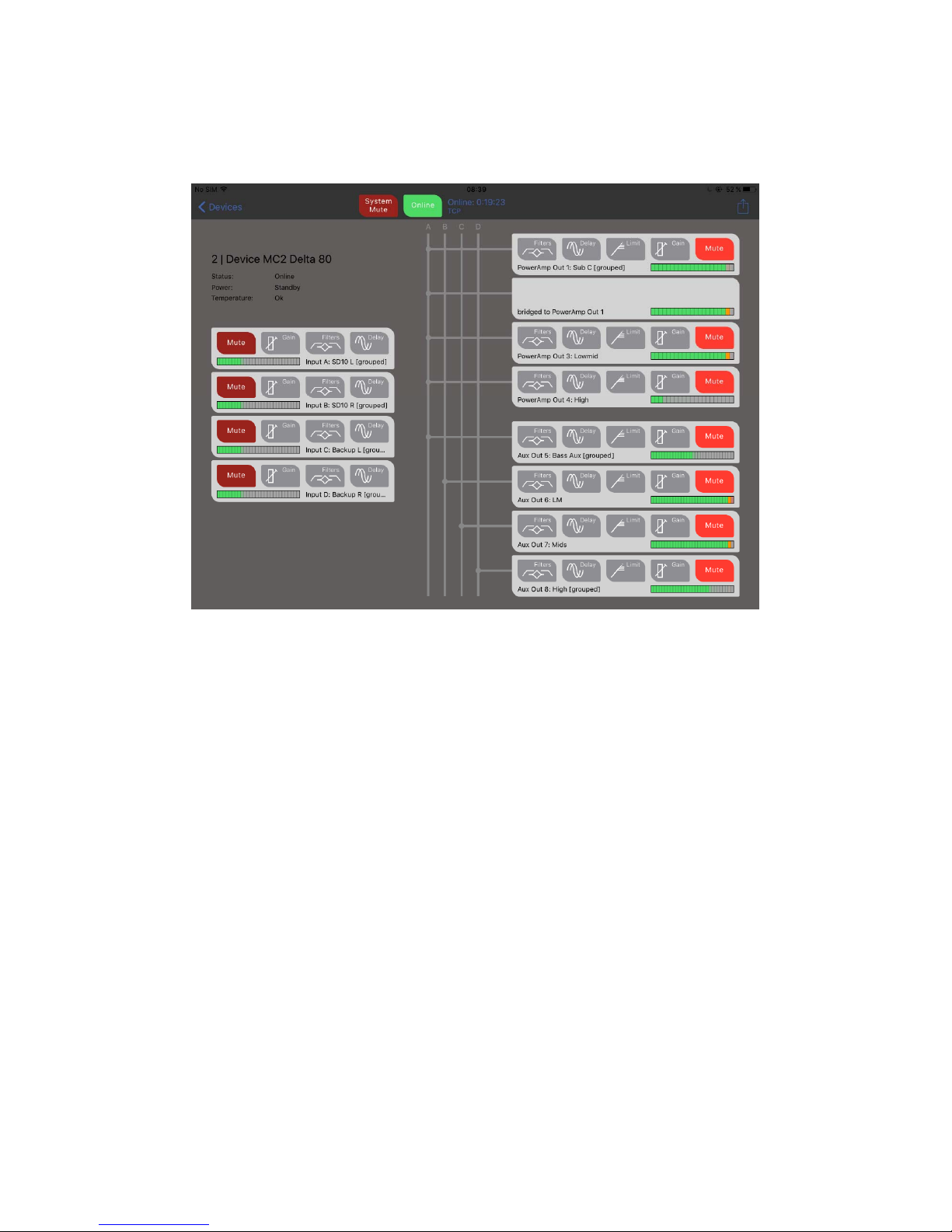
Once connected, all the amps appear on the default "All Devices" view, and real time metering should
start.
The amp’s icon on the left hand side of the virtual panel will show blue if the amplifier is running, grey
in standby and red if there is a fault or the amp goes off line (stops communicating). The meter group
for the outputs will also switch to show meters in greyscale if the power amp is in standby. DSP
continues to run and the aux outputs continue to function in standby, as does the network audio
interface (if fitted).
Page 6

DeltaDirect Quick Start Guide Page 6
The left hand icon on the amp's panel can be touched to reveal more info and adjust a selection of
device properties including its name (touch to edit), standby switching, AES switching, bridging
modes, and network output source selection (if audio network card is fitted).
The buttons along the bottom of the screen allow quick access to see all device, and all absolute and
relative groups. If grouping session data has been retrieved from amplifiers on the network, then this
area may populate with further buttons.
Page 7
DeltaDirect Quick Start Guide Page 7
Editing an Individual Device
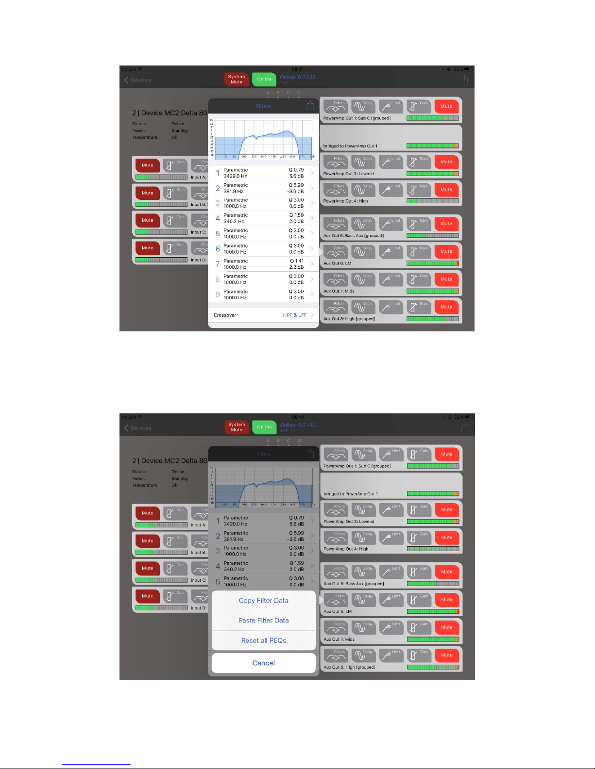
Touching an amplifier panel will open it up for editing:
Mute buttons directly mute outputs (if a meter is outlined in red it is muted elsewhere by a group
mute).
The inputs are shown on the left of the screen, and the outputs are arranged in two banks of four on
the right - main power amp DSP channels, then aux line level output DSP channels. Input channel
sources are accessed through the Gain buttons, and output polarity is accessed through the output
Gain buttons.
Delay and Limit buttons access input or output delays (polarity switching is additionally shown on
output delays tabs), with Limit opening the RMS and Peak Limiters (plus auto time constants
selection - across outputs or auxes in a bank of four). Filters will open a channel's EQ for editing...
Page 8
DeltaDirect Quick Start Guide Page 8
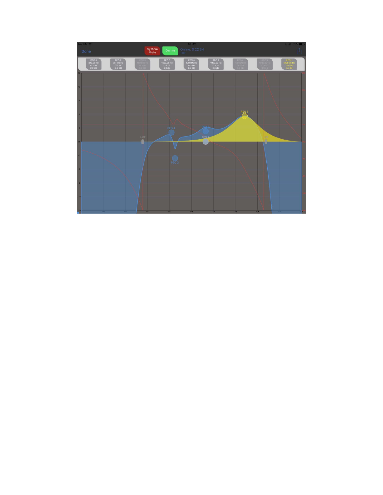
Individual bands may be edited by touching them in the table and directly moving slides or typing in
values. On outputs, the crossover filters are accessed at the bottom of the table. Bypassed bands
numbers are grey (like 3, 8 and 9 above). Touch the options top right on the window to reset all bands
and access copy and paste.
Touch the response graph to open full screen filter editing...
Page 9
DeltaDirect Quick Start Guide Page 9
Drag filter nodes to adjust frequency and gain. Pinch to adjust filter 'Q'. Touch the filter information
above the graph to edit directly with sliders and numeric input.
Touch options (top right) to reset a band, all bands and change what's shown - channel gain offset,
Xovers included, phase response. Also, select Autolock to move in one axis only when sweeping
curves - start moving vertically (adjusting a filter gain) and the frequency will lock and vice versa.
Page 10
DeltaDirect Quick Start Guide Page 10
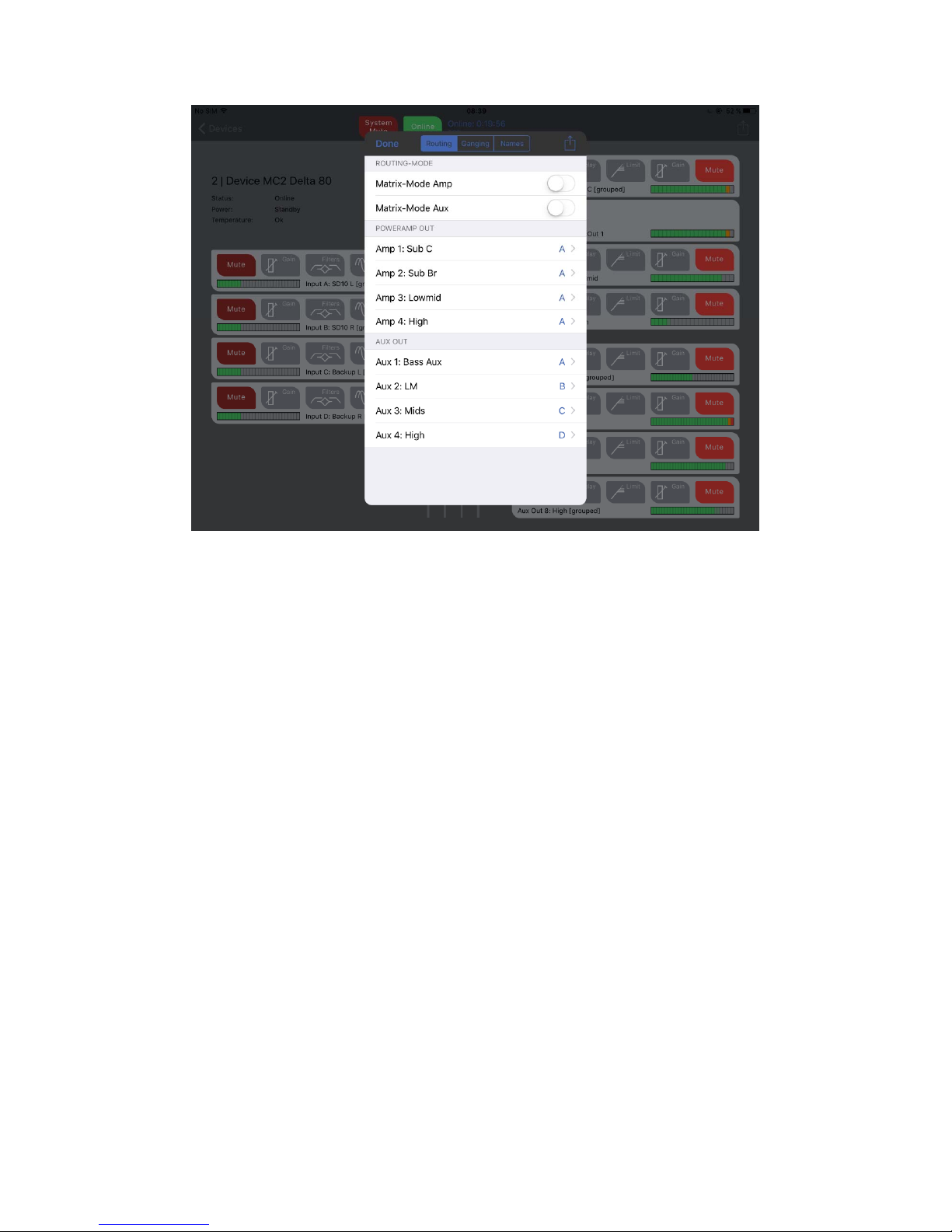
Touch routing matrix to access routing, channel ganging and channel naming. Full matrix mode can
also be enabled independently for the power amplifier channels and aux channels.
Page 11
DeltaDirect Quick Start Guide Page 11
Working With Groups
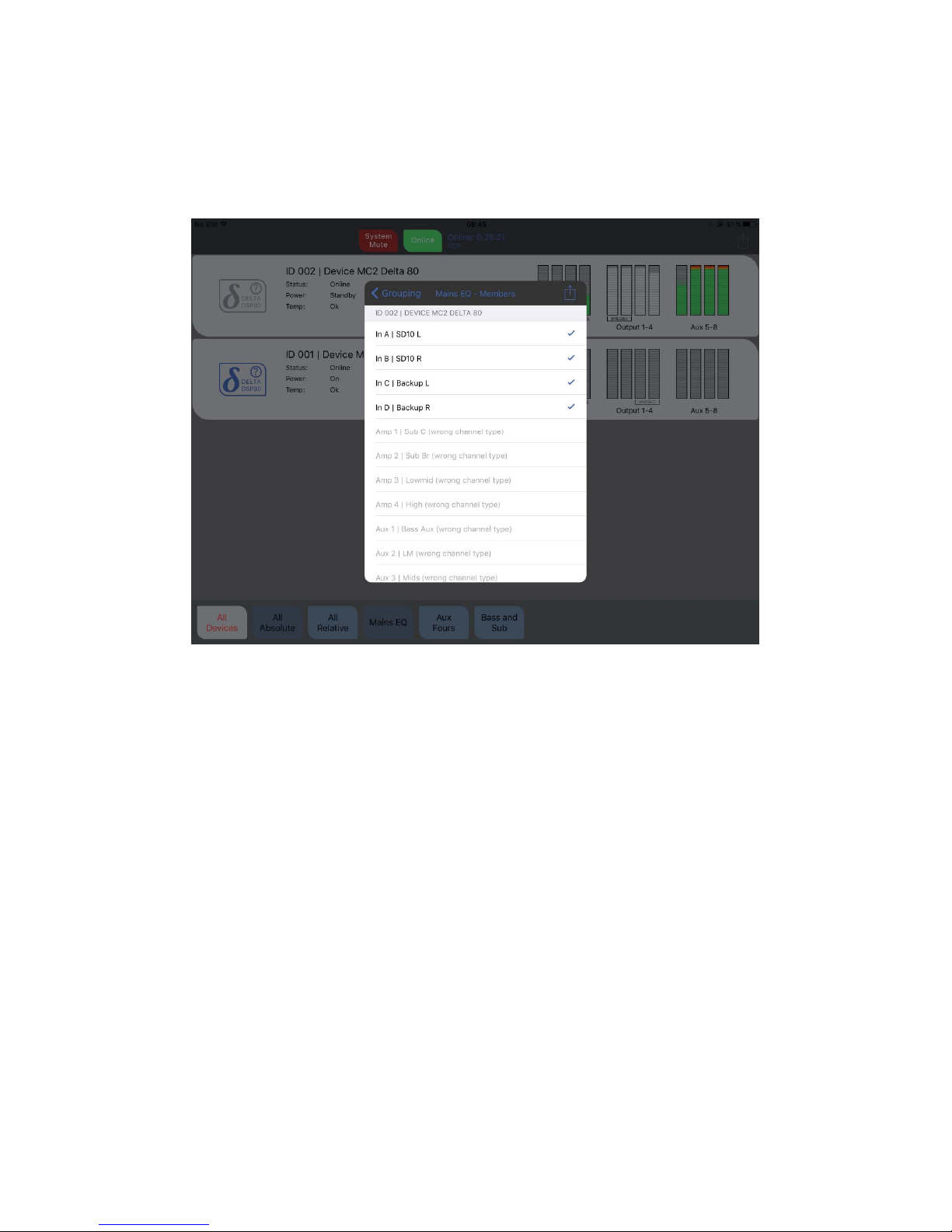
Advanced grouping architecture can be directly configured from the app, and grouping information is
stored in the amplifiers so can be retrieved when reconnecting. Touch the options in the top right of
the devices screen to select "Configure Grouping":
32 absolute groups and 32 relative groups are available. Absolute groups control multiple channels'
EQ at once, and all will track identically. Input and output channels cannot be mixed in a group.
Relative groups control the gains, delays and limiters (outputs only) by applying relative offsets to all
group members so they maintain their gain and delay relationships.
Limiter thresholds can only be adjusted down from their original settings (i.e. threshold lowered for
more protection).
All channels available for adding (or removing) from a group will be listed — adding the first member
will prompt for the group to be named. Channels can be added to multiple relative groups, but
channels can only exist in a single absolute group as these control EQ functions.
Page 12
DeltaDirect Quick Start Guide Page 12
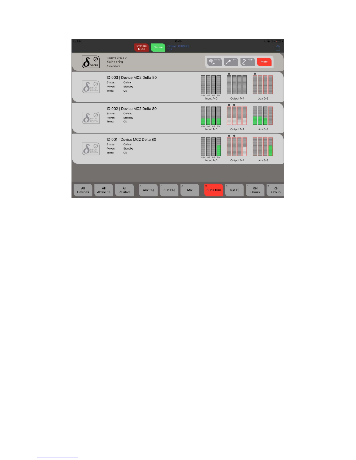
Groups appear below the devices on the main screen - Absolute groups have an "A" top left, relative
groups have an "R".
Touch a group to see its members (dots above channels on devices that are part of the
group). Controls for the group appear above the devices and can be directly edited. Muting a relative
group will make the group button turn red. Meters outlined in red indicate that they are muted at an
individual output level.
Page 13
DeltaDirect Quick Start Guide Page 13
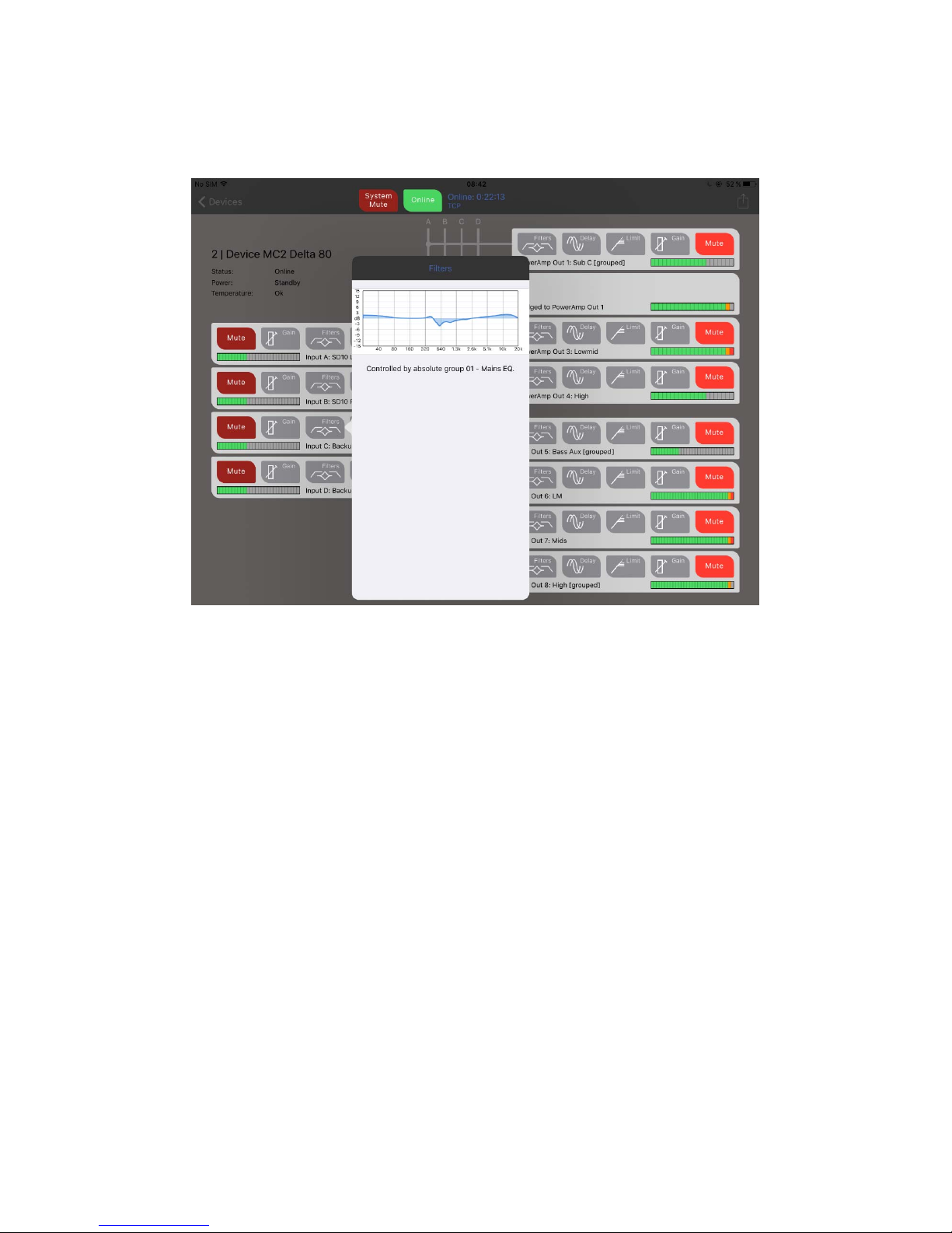
You can still access individual device channels when using grouping, but channels in absolute groups
will not allow EQ to be edited — they will show the EQ and detail which group they are part of so it’s
quick to switch to that group and make changes as required.
Page 14
DeltaDirect Quick Start Guide Page 14
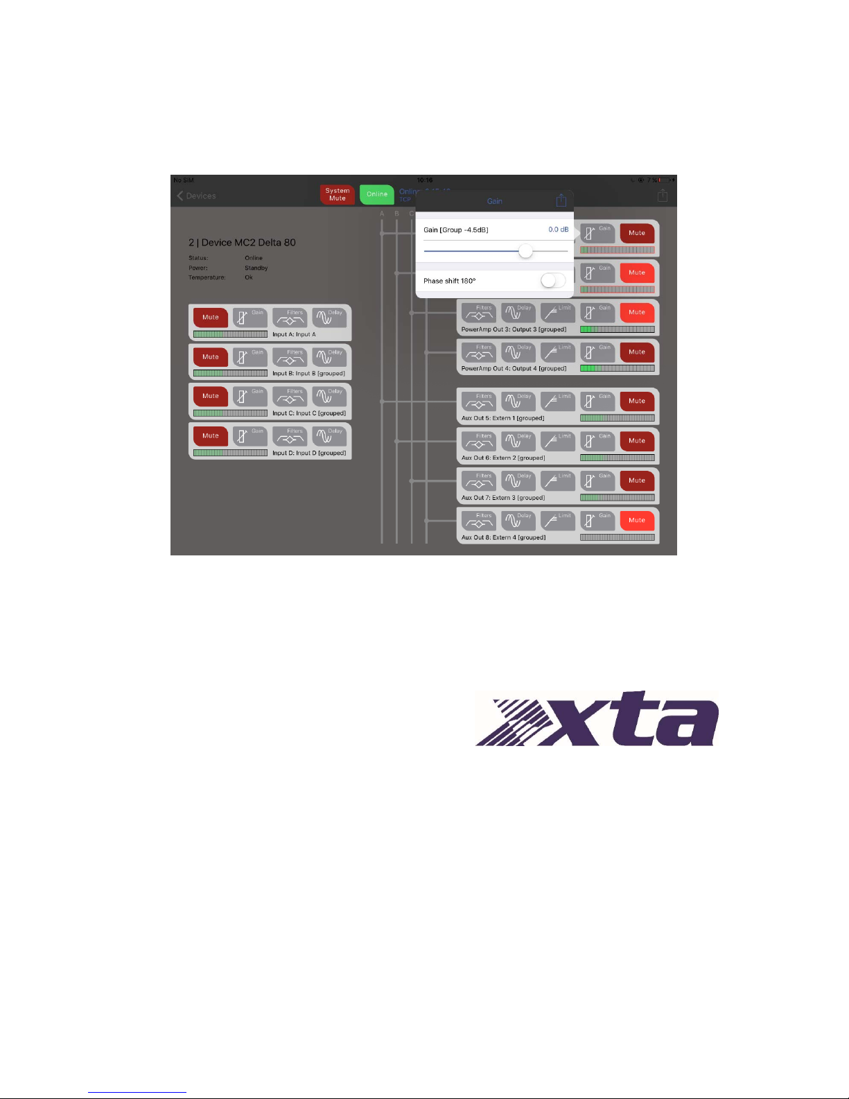
Still in the device view, grouping is shown beside channel names, and channels in an absolute group
cannot have EQ directly editing here. Channels in relative groups (a channel can be in multiple
relative groups) can still have their gain, delay and if an output, limiter threshold changed, and any
additional offset is shown in brackets beside the readout.
This value will be the aggregated value of all group memberships' offsets. Channel meters outlined
in red show that this channel is muted by a group.
Copyright XTA Electronics Ltd. 2017
 Loading...