

Page 1
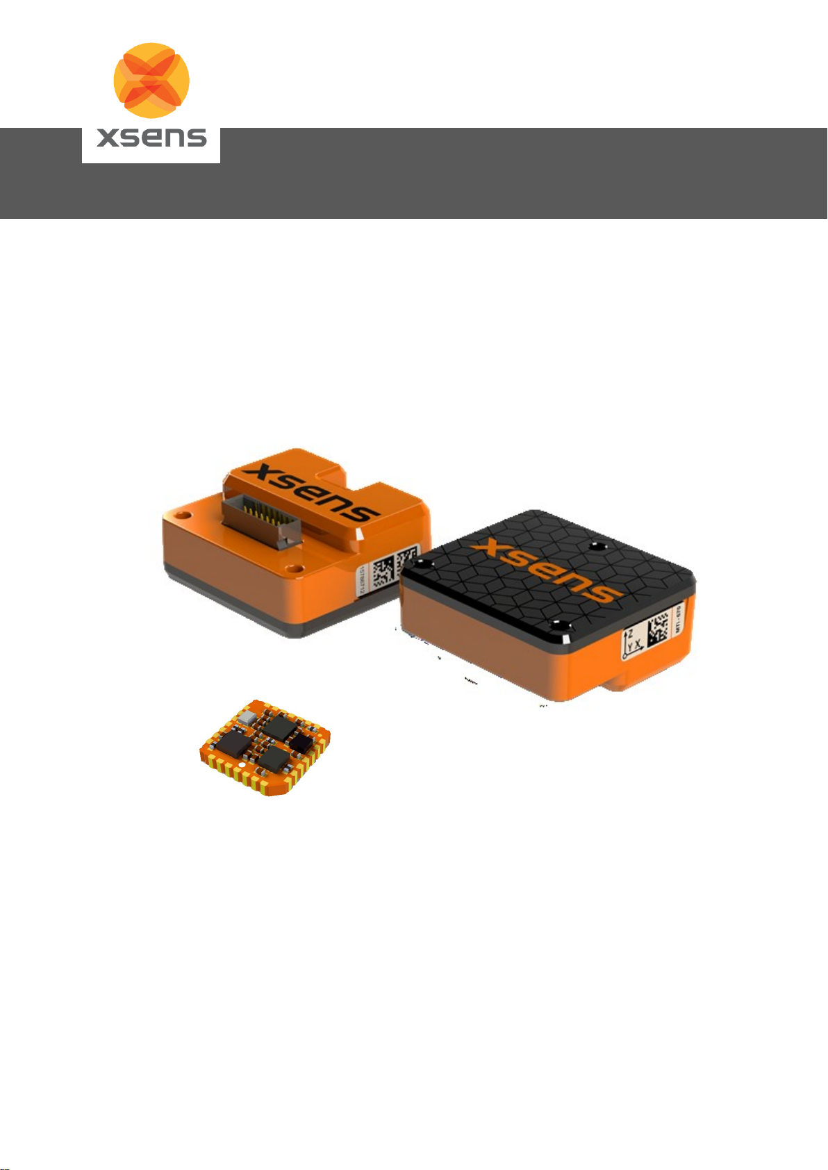
Xsens Technologies B.V.
Xsens North America, Inc.
Pantheon 6a
P.O. Box 559
7500 AN Enschede
The Netherlands
101 N, Pacific Coast Hwy
Suite 101
El Segundo, CA 90245
USA
Document MT1600P, Revision 2019.A, 29 Aug 2019
General information for MTi series
MTi Family Reference Manual
Page 2
ii
Document MT1600P.2019.A
© Xsens Technologies B.V.
MTi Family Reference Manual
Revisions
Revision
Date
By
Changes
A
© 2005-2019, Xsens Technologies B.V. All rights reserved. Information in this document is subject to
change without notice. Xsens, MVN, MotionGrid, MTi, MTx and Awinda are registered trademarks or
trademarks of Xsens Technologies B.V. and/or its parent, subsidiaries and/or affiliates in The
Netherlands, the USA and/or other countries. All other trademarks are the property of their respective
owners.
Page 3

iii
Document MT1600P.2019.A
© Xsens Technologies B.V.
MTi Family Reference Manual
Table of Contents
1 XSENS CUSTOMER SUPPORT AND BASE ................................................................................ 6
2 INTRODUCTION ............................................................................................................................ 7
2.1 FROM IMU TO GNSS/INS ............................................................................................................ 8
2.1.1 IMU .................................................................................................................................... 8
2.1.2 VRU ................................................................................................................................... 8
2.1.3 AHRS ................................................................................................................................. 8
2.1.4 GNSS/INS .......................................................................................................................... 8
2.2 XSENS MTI HARDWARE PLATFORMS .............................................................................................. 9
2.2.1 MTi 1-series ....................................................................................................................... 9
2.2.2 MTi 600-series ................................................................................................................... 9
2.2.3 MTi 10-series ..................................................................................................................... 9
2.2.4 MTi 100-series ................................................................................................................... 9
3 GETTING STARTED WITH THE MTI .......................................................................................... 11
3.1 OVERVIEW MTI DEVELOPMENT KIT .............................................................................................. 11
3.1.2 MT Software Development Kit (MT SDK) ........................................................................ 13
3.1.3 Low-level Communication ................................................................................................ 13
3.1.4 Terms of use of MT Software Suite ................................................................................. 13
4 MTI SYSTEM OVERVIEW ........................................................................................................... 15
4.1 TEST AND CALIBRATION .............................................................................................................. 15
4.2 COORDINATE SYSTEMS ............................................................................................................... 15
4.2.1 Calibrated inertial data and magnetic field data .............................................................. 15
4.2.2 Orientation increment and Velocity increment (dq and dv) ............................................. 16
4.2.3 Orientation data ............................................................................................................... 17
4.2.4 Velocity data .................................................................................................................... 18
4.2.5 Position data .................................................................................................................... 19
4.3 PHYSICAL SENSOR MODEL ........................................................................................................... 19
4.3.1 Calibrated ∆q and ∆v outputs .......................................................................................... 20
4.3.2 Calibrated inertial and magnetic data outputs ................................................................. 20
4.3.3 High-rate (HR) inertial data outputs ................................................................................. 20
4.3.4 Free acceleration ............................................................................................................. 21
4.4 XSENS SENSOR FUSION ALGORITHMS ......................................................................................... 22
4.4.1 Internal Sensor Bias Estimation....................................................................................... 22
4.4.2 Roll and Pitch estimation ................................................................................................. 22
4.4.3 Heading/yaw estimation ................................................................................................... 23
4.4.4 Velocity and Position estimation ...................................................................................... 23
4.4.5 Initialization ...................................................................................................................... 24
4.4.6 Filter Profile options ......................................................................................................... 24
4.4.7 Additional setting options and features ............................................................................ 24
4.5 MTI SERIES INTERFACE OPTIONS ................................................................................................. 26
4.6 TIMING AND SYNCHRONIZATION ................................................................................................... 26
5 INPUT AND OUTPUT SPECIFICATION...................................................................................... 27
5.1 OVERVIEW OF DATA OUTPUT PROTOCOLS .................................................................................... 27
5.2 OVERVIEW OF DATA INPUTS ......................................................................................................... 27
5.3 BUILT-IN SELF-TEST .................................................................................................................... 27
5.4 TIMESTAMP AND PACKET COUNTER OUTPUT ................................................................................. 27
5.5 STATUS WORD ............................................................................................................................ 28
Page 4

iv
Document MT1600P.2019.A
© Xsens Technologies B.V.
MTi Family Reference Manual
6 INSTALLATION TIPS AND TRICKS ........................................................................................... 29
6.1 TRANSIENT ACCELERATIONS ........................................................................................................ 29
6.2 VIBRATIONS ................................................................................................................................ 29
6.3 MAGNETIC MATERIALS AND MAGNETS ........................................................................................... 29
7 WARRANTY AND LIABILITY ...................................................................................................... 31
7.1 CUSTOMER SUPPORT ................................................................................................................. 31
Page 5

5
Document MT1600P.2019.A
© Xsens Technologies B.V.
MTi Family Reference Manual
List of Figures
Figure 1: From IMU to GNSS/INS ........................................................................................................... 8
Figure 2: MTi 1-series .............................................................................................................................. 9
Figure 3: MTi 600-series .......................................................................................................................... 9
Figure 4: MTi 10-series ............................................................................................................................ 9
Figure 5: MTi 100-series .......................................................................................................................... 9
Figure 6: MTi Development Kit .............................................................................................................. 11
Figure 7: Default coordinate system of MTi 1-series ............................................................................. 16
Figure 8: Default coordinate system of MTi 600-series ......................................................................... 16
Figure 9: Right hand rule ....................................................................................................................... 17
List of Tables
Table 1: MTi product documentation overview........................................................................................ 7
Table 2: Xsens MTi portfolio overview. ................................................................................................. 10
Table 3 Description of hardware components of Development Kit ....................................................... 11
Table 4 Description of software components of Development Kit......................................................... 12
Table 5: Conditions for the use of the MT Software Suite ..................................................................... 13
Table 6: Data outputs with reference coordinate systems .................................................................... 16
Table 7: Yaw in different coordinate systems (applies only to VRU/AHRS and GNSS/INS product types).
The MTi is assumed to be mounted with its roll-axis (X) aligned with the roll-axis of the vehicle (front of
the vehicle). ........................................................................................................................................... 18
Table 8: Output specifications ∆q and ∆v outputs ................................................................................. 20
Table 9: Output specifications inertial and magnetometer data outputs ............................................... 20
Table 10: Output specifications high rate calibrated inertial data outputs ............................................. 20
Table 11: Supplementary features and settings .................................................................................... 24
Table 12: overview of interface options in MTi portfolio ........................................................................ 26
Page 6

6
Document MT1600P.2019.A
© Xsens Technologies B.V.
MTi Family Reference Manual
1 Xsens Customer Support and BASE
BASE by Xsens is an online support platform with a knowledge base and community forum on 3D motion
tracking technology and products. This enables faster and easier system integration by offering a large
source of high-quality technical information.
Knowledge base (FAQ)
The knowledge base provides articles written by Xsens Field Application Engineers and Product
Specialists. Topics discussed are best practices, tips and tricks for the use of Xsens’ products and inside
information about installation, MEMS sensors and GNSS receivers, hardware design, CAD-files, system
architecture, low-level communication and sensor fusion algorithms.
Community forum
The community forum is an online forum that gives direct access to Xsens’ engineers and other Xsens
users. As users may have faced similar challenges, the answer may already be on the forum.
The knowledge base and user community are searchable simultaneously. A search query thus shows
results irrespective of the source.
Please visit https://base.xsens.com to complete your 1-minute registration.
Additionally, tutorial videos on products, features and releases are available on BASE by Xsens via:
https://tutorial.xsens.com/.
Page 7
7
Document MT1600P.2019.A
© Xsens Technologies B.V.
MTi Family Reference Manual
2 Introduction
This manual gives an overview of the latest generation Xsens products (MTi 1-series and MTi 600series) and their usage. For previous generations, refer to MTi User Manual1. The MTi product portfolio
from Xsens currently has family members ranging in functionality from Inertial Measurement Units
(IMU’s), Vertical Reference Unit (VRU), Attitude and Heading Reference System (AHRS) to a fully
integrated GNSS/INS (Global Navigation Satellite System/Inertial Navigation System). All products
contain a 3D IMU composed by a gyroscope and an accelerometer plus a 3D magnetometer, with
optionally a barometer and GNSS receiver.
The MTi product range is divided in several series, the MTi 1-series, the MTi 600-series, the MTi 10series and the MTi 100-series.
The MTi 1-series is a low-cost Surface-Mount Devices (SMD) module.
The MTi 600-series is a cost effective product line for easy integration.
The MTi 10-series2 is Xsens’ entry level model with robust accuracy.
The MTi 100-series is a Xsens’ proven high end class of MEMS IMU’s, orientation and position sensor
modules.
Table 1 summarizes all available official documents for the Xsens MTi product line. It is highly
recommended to review all documents applicable to your Xsens Motion Tracker.
Table 1: MTi product documentation overview1
MTi 1-series
MTi 600-series
MTi 10/100-series
MTi Family Reference Manual
MTi User Manual
MTi 1-series Datasheet
MTi 600-series Datasheet
MTi 1-series DK User Manual
MTi 600-series DK User Manual
MTi 1-series HW Integration Manual
MTi 600-series HW Integration Manual
MT CAN Protocol Documentation
MT Manager Manual
Magnetic Calibration Manual
MT Low Level Communication Protocol Documentation
Firmware Updater User Manual
1
Links to the latest available documentation can be found via the following link: Xsens MTi Documentation
2
not recommended for new designs
Page 8
8
Document MT1600P.2019.A
© Xsens Technologies B.V.
MTi Family Reference Manual
2.1 From IMU to GNSS/INS
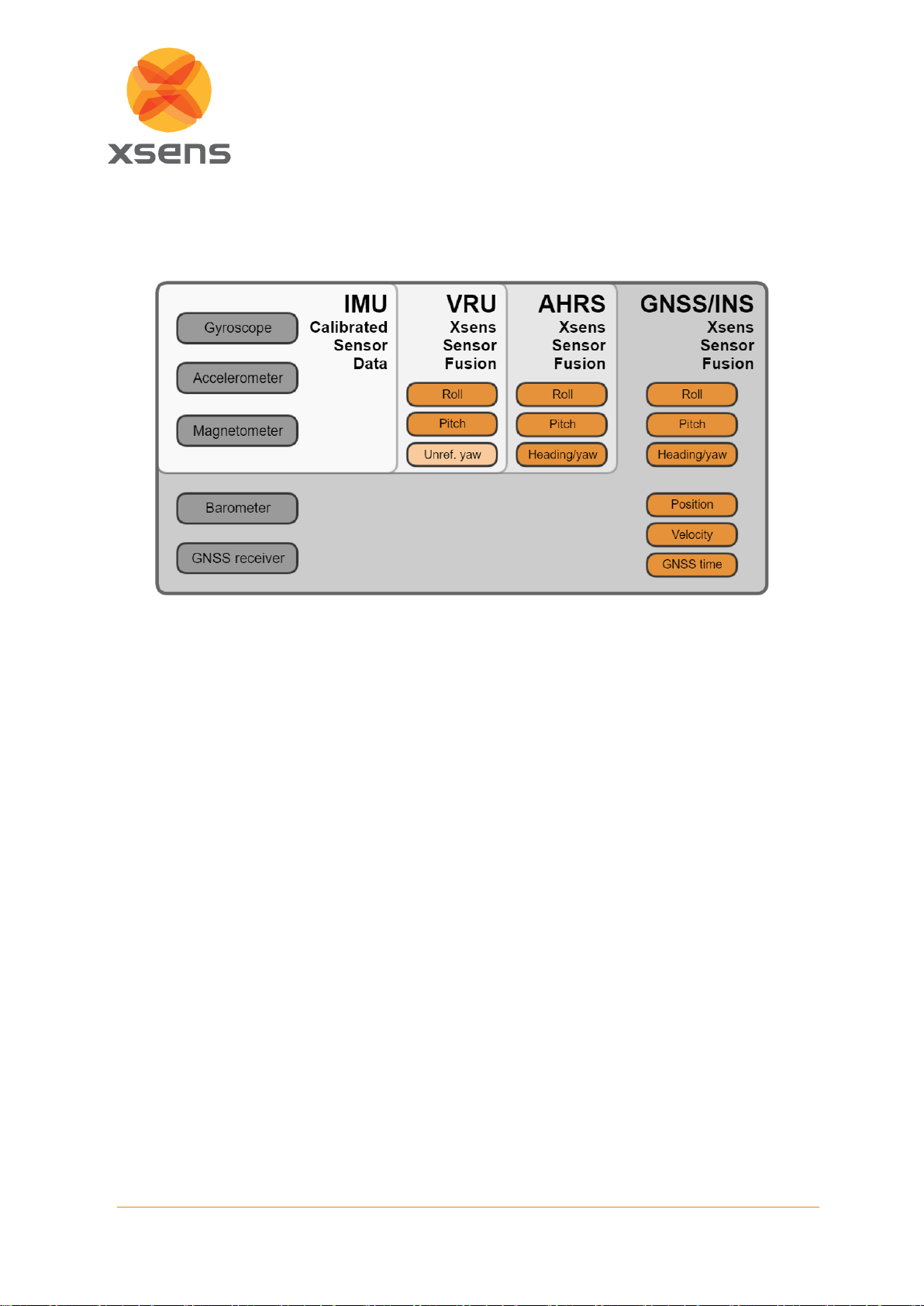
Within each MTi series, Xsens offers several product variants. Each variant is based on a firmware
version which enables different functionalities. Figure 1 summarizes the functionality of each variant.
Figure 1: From IMU to GNSS/INS
2.1.1 IMU
The IMU variant is an Inertial Measurement Unit that measures 3D acceleration and 3D rate of turn with
the addition of 3D magnetic field data and, depending on the product, barometric pressure. It does not
fuse sensor data to deliver orientation estimates. The IMU can also be configured to output data
generated by the strapdown integration algorithm (orientation increments ∆q and velocity increments
∆v).
2.1.2 VRU
The Vertical Reference Unit (VRU) adds the first layer of algorithms which uses gravity as a reference
for roll and pitch calculations. Essentially it delivers the same data as the AHRS, except for the yaw.
The yaw estimate of a VRU product is unreferenced, which means that it is computed without any
geographic/magnetic reference, though still superior to just gyroscope integration (e.g., when using the
gyro bias estimation techniques). All data outputs from the IMU are also available in this product version.
The AHS feature is also available in this product variant (see also chapter 4.4.7)
2.1.3 AHRS
This is the full Attitude and Heading Reference System (AHRS). It gives various outputs: roll, pitch and
heading (true magnetic North referenced yaw). In addition, all functionality of the IMU and VRU are also
available in this product variant.
2.1.4 GNSS/INS
The GNSS/INS variant is a product with an interface to an external or internal GNSS receiver as well as
a barometer. It provides roll, pitch, yaw/heading, as well as 3D position, 3D velocity and time data. In
addition, all data outputs of the IMU, VRU and AHRS are also available in this product variant.
Page 9
9
Document MT1600P.2019.A
© Xsens Technologies B.V.
MTi Family Reference Manual
2.2 Xsens MTi hardware platforms
This section summarizes all available Xsens MTi platforms (see Table 2).
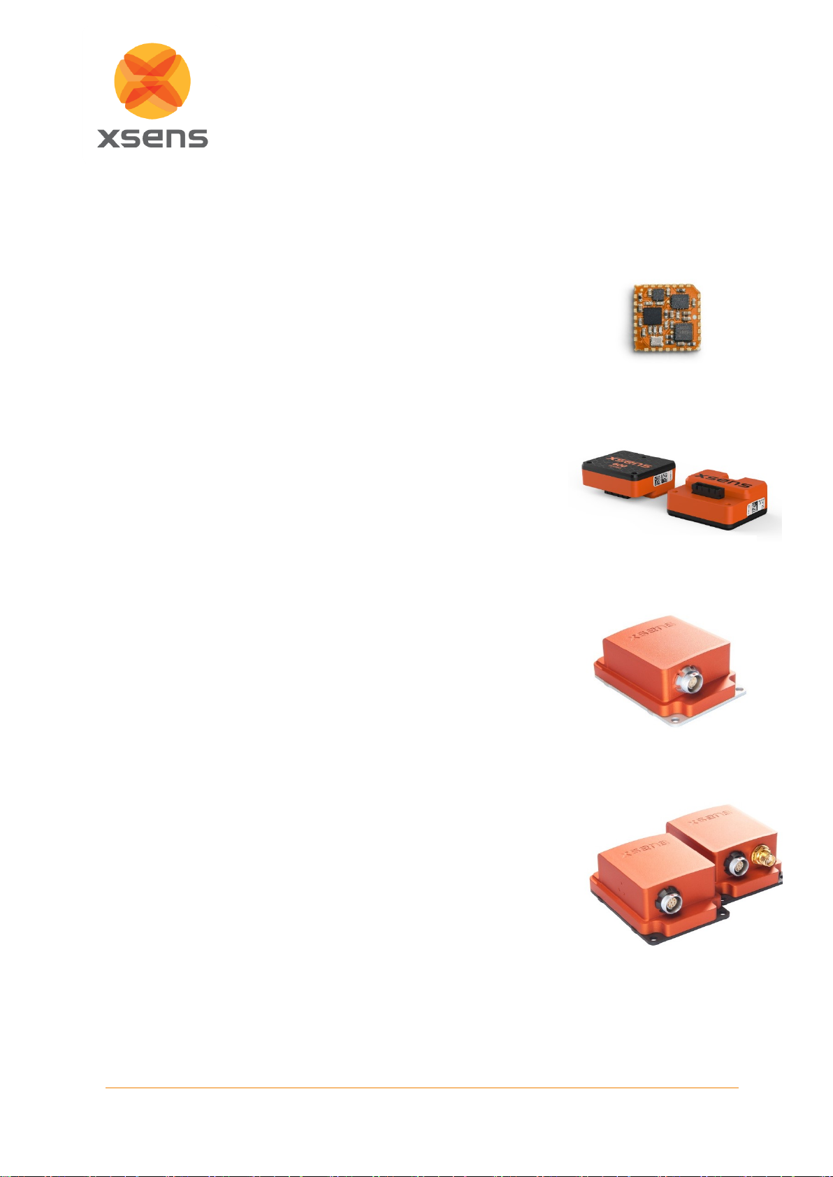
2.2.1 MTi 1-series
The MTi 1-series is the Xsens’ smallest (12.1mm x 12.1mm), lightest (<1gr)
and most cost effective product suitable for SMD (Surface Mountable
Device) integration. It is compatible with the JEDEC PLCC-28 standard
footprint. Designed for integration in high volume applications.
Available in IMU, VRU, AHRS and GNSS/INS (with external GNSS
receiver) product versions.
Please refer to the MTi 1-series Datasheet for more information.
2.2.2 MTi 600-series
The MTi 600-series product line is designed to be lightweight, cost effective
and easy to integrate. It can be integrated in two ways: either with the
header facing downwards, directly mounted on a PCB, or standalone, using
a flat cable for communication. Additionally it features a CANbus interface.
Available in IMU, VRU, AHRS and GNSS/INS (with external GNSS
receiver) product versions.
Please refer to the MTi 600-series Datasheet for more information.
2.2.3 MTi 10-series
The MTi 10-series offers inertial and orientation data at an affordable price.
It features a sturdy anodized aluminium housing, and robust push/pull
connectors. The MTi-10 series can easily be recognized by the aluminium
silver base plate.
Available in IMU, VRU and AHRS product versions.
Please refer to the MTi User Manual for more information. This product is
not recommended for new designs.
2.2.4 MTi 100-series
The MTi-100 series is the high-performance product range of the MTi
product portfolio, with accuracies surpassing conventional MEMS motion
trackers, because of the use of superior gyroscopes and a new optimization
filter, going beyond standard Extended Kalman Filter implementations. In
addition, the factory calibration is more accurate, repeatable and robust.
The MTi 100-series can be recognized by the dark-grey/black base plate
and the small barometer holes on one side of the casing. The MTi-G-710
has an extra SMA connector to allow a GNSS antenna to be attached.
Available in IMU, VRU, AHRS and GNSS/INS (with internal GNSS receiver)
product versions.
Please refer to the MTi User Manual for more information.
Figure 2: MTi 1-series
Figure 3: MTi 600-series
Figure 4: MTi 10-series
Figure 5: MTi 100-series
including the MTi-G-710
Page 10

10
Document MT1600P.2019.A
© Xsens Technologies B.V.
MTi Family Reference Manual
Table 2: Xsens MTi portfolio overview.
MTi 1-series
MTi 600-series
MTi 10-series
MTi 100-series
IMU
MTi-1 IMU
MTi-610 IMU
MTi-10 IMU
MTi-100 IMU
VRU
MTi-2 VRU
MTi-620 VRU
MTi-20 VRU
MTi-200 VRU
AHRS
MTi-3 AHRS
MTi-630 AHRS
MTi-30 AHRS
MTi-300 AHRS
GNSS/INS
MTi-7 GNSS/INS
MTi-670 GNSS/INS
-
MTi-G-710 GNSS/INS
This document focusses mainly on the MTi 1-series and MTI 600-series. For more information on the
MTi 10-series and MTi 100-series, please refer to the MTi User Manual.
Page 11
11
Document MT1600P.2019.A
© Xsens Technologies B.V.
MTi Family Reference Manual
3 Getting Started with the MTi
3.1 Overview MTi Development Kit
The MTi development kit is a very easy to use starter’s kit that allows for fast and easy integration of the
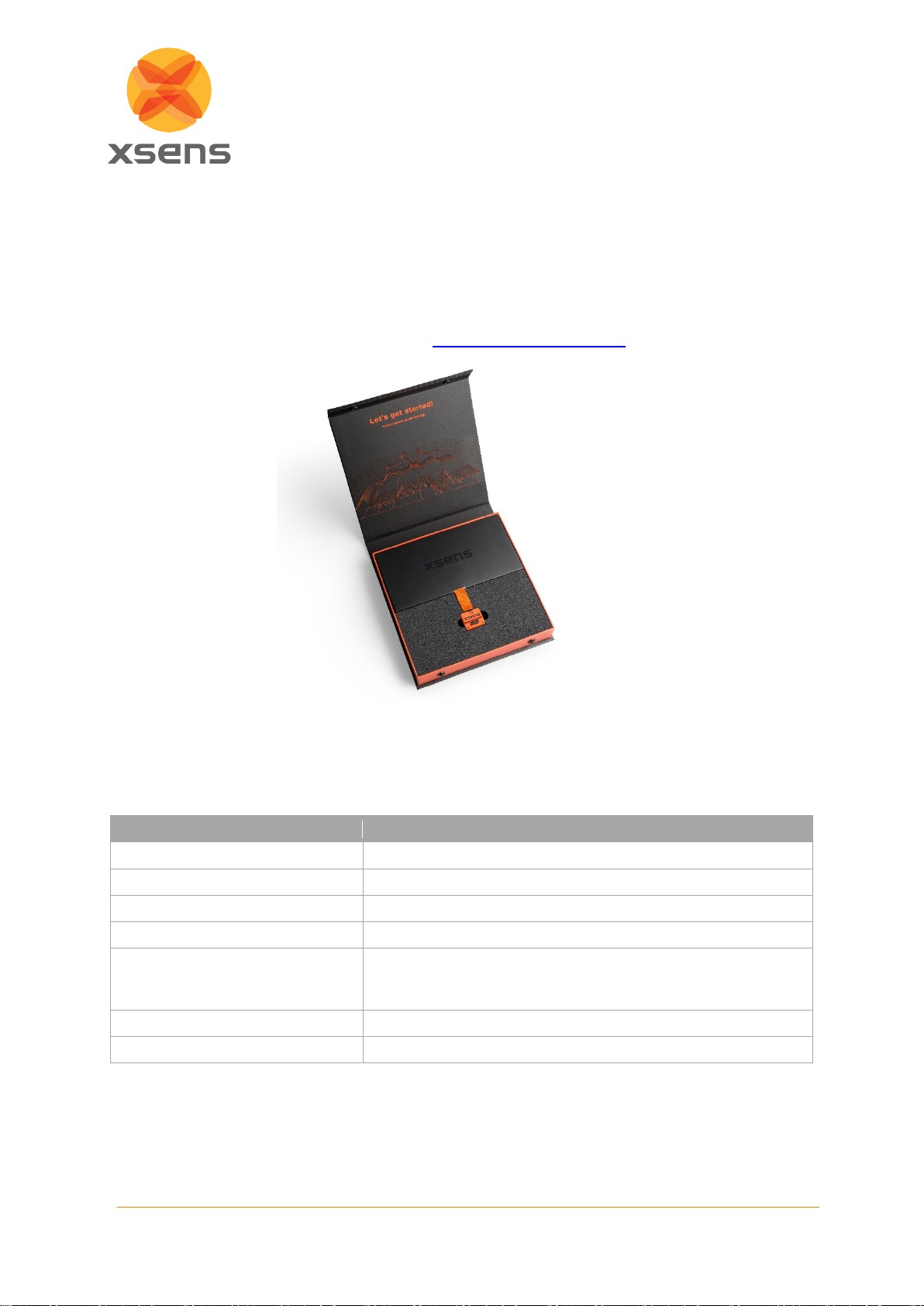
MTi in any user scenario. Figure 6 shows a typical Development Kit, containing an MTi. All software and
installation instructions are available online via http://www.xsens.com/setup.
Figure 6: MTi Development Kit
Depending on the model of MTi you have purchased, the Development Kit can contain any of the
following items:
Table 3 Description of hardware components of Development Kit
Component
Description
An MTi Motion Tracker
Development board
A tool for prototyping and validation
(micro) USB (converter) cable
A cable to connect the MTi device to a USB port
multi-purpose (flat) cable
A cable which exposes all physical lines to a MTi device
GNSS daughter card
An accessory which fits the MTi 1-series and MTi 600-series
development board which contains a GNSS receiver (clickboardTM compatible)
GNSS antenna
Test and Calibration certificate
Page 12
12
Document MT1600P.2019.A
© Xsens Technologies B.V.
MTi Family Reference Manual
Table 4 Description of software components of Development Kit
Component
Description
MT Software Suite (MTSS)
available for download via http://www.xsens.com/setup
Xsens MTi USB driver
Part of the MTSS
MT Manager for Linux and
Windows
Part of the MTSS
MT Software Development Kit (MT
SDK) for multiple OS
Part of the MTSS, containing the following components:
• XDA public source files (C, C++ wrapper ; any OS)
• Example source code and examples
o C++
o C#
o Python
o MATLAB
o Robotic Operating System (ROS)
o Embedded examples (ST Nucleo)
Magnetic Field Mapper – MFM
(Windows and Linux)
Part of the MTSS, containing the following component:
• MFM SDK (Windows and Linux)
Firmware Updater
Separate component design to update MTi device firmware
Documentation
Part of the MTSS, PDFs are available online, containing the
following components:
• Links to online manuals
• Xsens Device API library
MFM SDK Library
Library for the Magnetic Field Mapper
3.1.1 Getting Started with MT Manager software
The easiest way to get started with your MTi is to use MT Manager. MT Manager is a software tool to
easy get to know and to demonstrate the capabilities of the MTi and to configure the device to suit your
needs.
Additionally MT Manager allows you to:
• record data and playback/review data;
• view orientation, position and velocity in real-time;
• view inertial and magnetic sensor data in real time;
• view low-level communication and XDA communication via message terminals;
• export log files to ASCII and KMZ (format viewable in Google Earth);
• change and/or view various device settings and properties;
• reprocess recorded data with different settings.
NOTE: the most recent version of the software, source code and documentation can always be
downloaded on www.xsens.com/mt-software-suite. Links to documentation can be found on BASE:
http://xsens.com/xsens-mti-documentation
The latest firmware and firmware updater can be found here: https://www.xsens.com/mt-firmware/
Page 13
13
Document MT1600P.2019.A
© Xsens Technologies B.V.
MTi Family Reference Manual
Please refer to the MT Manager User Manual3 for more information on MT Manager.
3.1.2 MT Software Development Kit (MT SDK)
The Xsens Device API (XDA) serves as a starting point for system integrators interested in assessing
the basics of the SDK. The main objective of the SDK is to facilitate the development of user-specific
host applications based on Xsens motion trackers.
The MT Software Development Kit (MT SDK), part of the MT Software Suite installation, provides
examples based on XDA for multiple programming languages. These programming examples can be
used as a starting point for further software development.
The MT SDK 2019.x (and the MT Software Suite) is designed for the MTi 1-series, MTi 600-series, MTi
10-series and MTi 100-series. Links to the latest available documentation can be found via the following
link: Xsens MTi Documentation
See also: Introduction to the MT SDK programming examples for MTi devices
3.1.3 Low-level Communication
The low-level communication protocol (named Xbus protocol) offers full control and functionality. It is
essential on platforms that do not support the Xsens Device API, such as custom embedded computers
and microcontrollers.
The low-level communication is extensively described in the MT Low-Level Communication Protocol
Documentation3. Next to that, source code is delivered to make driver development and Xbus message
parsing for the MTi as easy and quick as possible.
3.1.4 Terms of use of MT Software Suite
The installer of the MT Software Suite can install 4 components: MT Manager, MT SDK, Magnetic Field
Mapper (MFM) and MFM SDK. The Firmware Updater is a separate installer. The MT Software Suite
has a Restricted License Agreement that you need to accept. In Table 5, the conditions for use of each
component are summarized.
Table 5: Conditions for the use of the MT Software Suite
Component
Conditions
MT Manager
For use with Xsens products only
Not allowed to re-distribute
Not allowed to reverse engineer
Not allowed to modify
MT SDK
For use with Xsens products only
Allowed to re-distribute “as is” or embed in programs
Not allowed to reverse engineer
Allowed to execute, reproduce, modify and compile (modified) source
code to use with Xsens products only
Not allowed to modify DLL
Include License Agreement with distribution
MFM
For use with Xsens products only
Allowed to re-distribute “as is”
Not allowed to reverse engineer
Not allowed to modify
Include License Agreement with distribution
3
Links to the latest available documentation can be found via the following link: Xsens MTi Documentation
Page 14

14
Document MT1600P.2019.A
© Xsens Technologies B.V.
MTi Family Reference Manual
MFM SDK
For use with Xsens products only
Allowed to re-distribute “as is” or embed in programs
Not allowed to reverse engineer
Allowed to execute, reproduce, modify and compile (modified) source
code to use with Xsens products only
Not allowed to modify DLL
Include License Agreement with distribution
FWU
For use with Xsens products only
Allowed to re-distribute “as is”
Not allowed to reverse engineer
Not allowed to modify
Include License Agreement with distribution
Page 15

15
Document MT1600P.2019.A
© Xsens Technologies B.V.
MTi Family Reference Manual
4 MTi System Overview
4.1 Test and Calibration
A correct calibration of the sensor components inside the MTi is essential for an accurate output. The
quality and importance of the calibration are of highest priority. Each Xsens’ MTi is calibrated and tested
by subjecting each device to a wide range of motions and temperatures.
The individual calibration parameters are used to convert the sensor component readout (digitized
voltages) to physical quantities as accurately as possible, compensating for a wide range of deterministic
errors. Additionally, the calibration values are used in Xsens sensor fusion algorithms, as discussed
later in this document.
Each MTi contains individual test and calibration data in its eMTS (electronic Motion Tracker Settings).
It is digitally signed by a Test Person and states the calibration values determined during the calibration
of the MTi at Xsens’ calibration facilities. The values can be seen by connecting the MTi to MT Manager
and navigating to Device Settings → Modelling Parameters.
Next to the calibration values shown in MT Manager, each device is calibrated according to more
complicated models to ensure accuracy (e.g. non-linear temperature effect, cross coupling between
acceleration and angular rate4).
4.2 Coordinate systems
Data from the MTi is represented in various coordinate systems, which are explained below.
4.2.1 Calibrated inertial data and magnetic field data
The default sensor-fixed frame (S
xyz
) is a right-handed Cartesian coordinate system that is fixed to the
device. When the sensor is rigidly attached to another object or vehicle but not aligned, it may be
convenient to rotate the sensor coordinate system S
xyz
to an object coordinate system (O
xyz
).
Refer to BASE by Xsens - MTi reference co-ordinate systems for more information on the available
orientation resets.
S
xyz
or O
xyz
are the coordinate frames used to express the rate of turn, acceleration and magnetic field
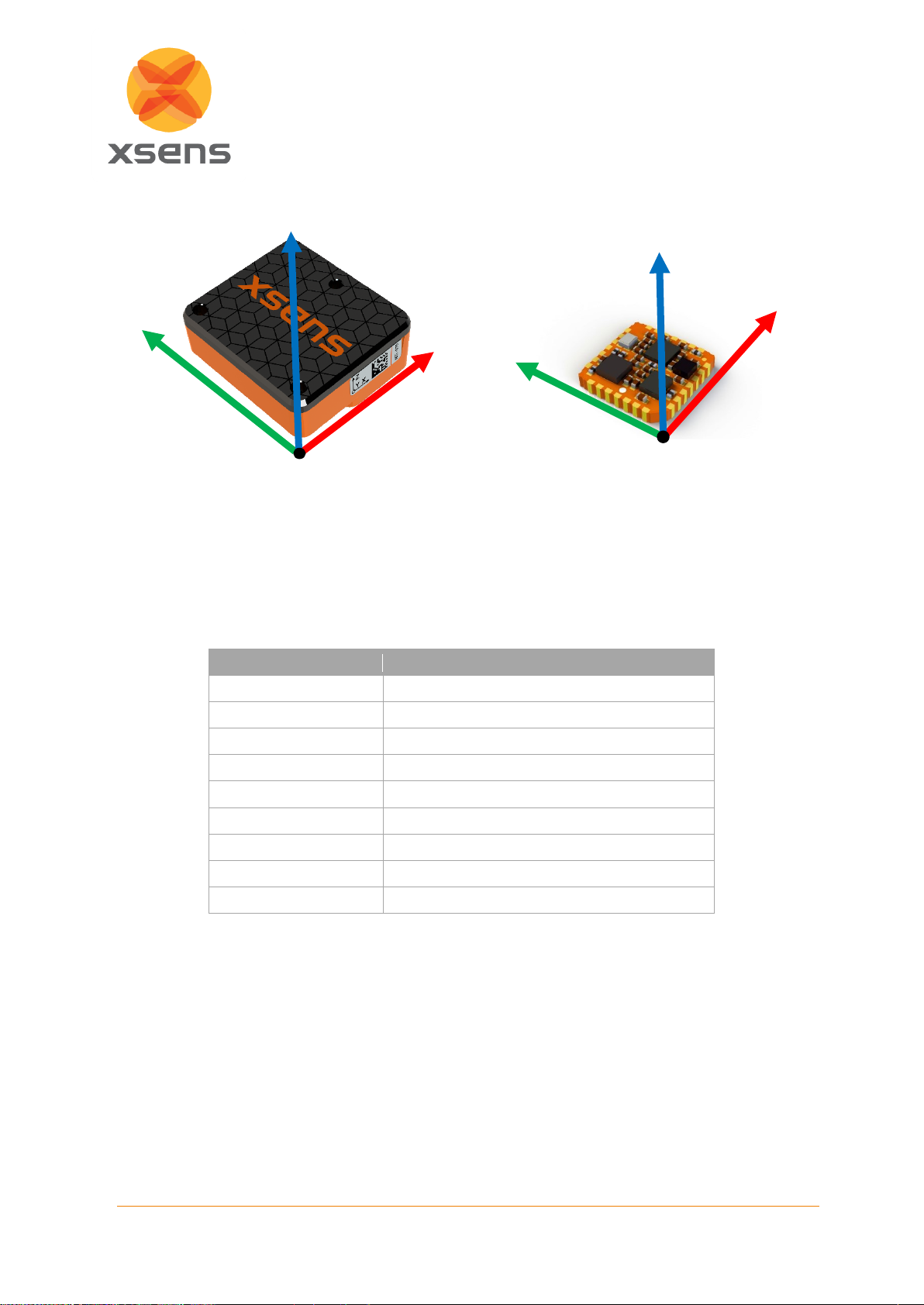
outputs. The encased version of the MTi shows S
xyz
on the sticker. Figure 8 and Figure 7 depict the
sensor coordinate system on the MTi 600-series and MTi 1-series. Later in this document, small x, y
and z are the axes labels for S
xyz
and O
xyz
. Capital X, Y and Z stand for the local-earth fixed coordinate
system (L
XYZ
).
4
Also known as “g-sensitivity”.
Page 16
16
Document MT1600P.2019.A
© Xsens Technologies B.V.
MTi Family Reference Manual
The housing and PCB of the MTi 600-series are carefully aligned with the output coordinate system
during the individual factory calibration. The non-orthogonality between the axes of S
xyz
is <0.05. This
also means that the output of 3D linear acceleration, 3D rate of turn and 3D magnetic field data all will
have orthogonal xyz readings within <0.05.
Some of the commonly used data outputs and their reference coordinate systems are listed in Table 6.
Table 6: Data outputs with reference coordinate systems
Data
Reference coordinate system
Acceleration
Sensor-fixed frame (S
xyz
) or O
xyz
Rate of turn
Sensor-fixed frame (S
xyz
) or O
xyz
Magnetic field
Sensor-fixed frame (S
xyz
) or O
xyz
Velocity increment
Sensor-fixed frame (S
xyz
) or O
xyz
Orientation increment
Sensor-fixed frame (S
xyz
) or O
xyz
Free acceleration
Local earth-fixed frame (L
XYZ
), default ENU
Orientation
Local earth-fixed frame (L
XYZ
), default ENU
Velocity
Local earth-fixed frame (L
XYZ
), default ENU
Position
Local earth-fixed frame (L
XYZ
), default ENU
4.2.2 Orientation increment and Velocity increment (dq and dv)
The Strap Down Integration (SDI) output of the MTi contain orientation increments (dq) and velocity
increments (dv). These values represent the orientation change and velocity change during a certain
interval based on the output rate. The output rate is selectable up to 100 Hz or 400 Hz depending on
the product. The dq and dv values are always represented in the same coordinate system as calibrated
inertial data and magnetic field data, which can be S
xyz
or O
xyz
.
Figure 8: Default coordinate system of MTi 600-series
Z
X
Y
Figure 7: Default coordinate system of MTi 1-series
Z
X
Page 17

17
Document MT1600P.2019.A
© Xsens Technologies B.V.
MTi Family Reference Manual
4.2.3 Orientation data
By default, the local earth-fixed reference coordinate system L
XYZ
is defined as a right-handed Cartesian
coordinate system with5:
• X positive to the East (E).
• Y positive to the North (N).
• Z positive when pointing up (U).
This coordinate system is known as ENU (East-North-Up) and is the standard in inertial navigation for
aviation and geodetic applications. Note that it is possible to change L
XYZ
using a different convention,
like NWU (North-West-Up) or NED (North-East-Down), by changing an alignment matrix or applying an
orientation reset.
The 3D orientation output is defined as the orientation between the body-fixed coordinate system, S
xyz
or O
xyz
, and the local earth-fixed co-ordinate system, L
XYZ
.
Orientation output modes
The output orientation can be presented in different equivalent representations:
• Unit Quaternions;
• Euler angles6: roll, pitch, yaw (XYZ Earth fixed type) are output following the aerospace
sequence (Z-Y’-X”);
• Rotation Matrix (directional cosine matrix).
A positive rotation is always “right-handed”, i.e. defined according to the right-hand rule (corkscrew rule),
see Figure 9. This means a positive rotation is defined as clockwise in the direction of the axis of rotation.
Figure 9: Right hand rule
Refer to BASE by Xsens to find more information on how quaternions, Euler angles and the rotation
matrix relate to each other.
5
The default reference coordinate system L
XYZ
only applies to the MTi in Normal output mode. Refer to the Low
Level Communication Protocol Documentation for detailed orientation output specifications when using the ASCII
(NMEA) output mode.
6
Please note that due to the definition of Euler angles there is a mathematical singularity when the sensor-fixed x-
axis is pointing up or down in the earth-fixed reference frame (i.e. pitch approaches ±90). In practice, this means
roll and pitch is not defined as such when pitch is close to ±90 deg. This singularity is in no way present in the
quaternion or rotation matrix output mode.
Page 18

18
Document MT1600P.2019.A
© Xsens Technologies B.V.
MTi Family Reference Manual
Interpretation of yaw as heading
Heading is defined as the angle between the north direction and the horizontal projection of the roll axis.
Heading is positive about the local vertical axis following the right-hand rule7.
With the default ENU L
XYZ
coordinate system, Xsens yaw output is defined as the angle between East
(X) and the horizontal projection of the sensor roll axis (x), positive about the local vertical axis (Z)
following the right-hand rule. Table 7 shows the different yaw values corresponding to the different local
coordinate systems that are available for the MTi.
Table 7: Yaw in different coordinate systems (applies only to VRU/AHRS and GNSS/INS product types). The
MTi is assumed to be mounted with its roll-axis (X) aligned with the roll-axis of the vehicle (front of the
vehicle).
Local coordinate
system (output)
Roll-axis of the vehicle
Yaw value
East-North-Up (ENU)
Pointing North
90 deg
East-North-Up (ENU)
Pointing East
0 deg
North-West-Up (NWU)
Pointing North
0 deg
North-East-Down (NED)
Pointing North
0 deg
When using the ENU convention (default), the yaw output is 0º when the vehicle (x -axis of the MTi) is
pointing East (X axis of L
XYZ
). When it is required that the yaw output is 0º when the x-axis of the MTi is
pointing North, it is recommended to select NWU or NED as the local coordinate system. In section 0
the various alignment resets are described.
When using the INS/GNSS products in an automotive application, as a best practice pay proper attention
to mounting of the MTi on the automotive platform/vehicle. It is recommended to always mount the MTi
with the x-axis pointing to the front of the vehicle irrespective of the local coordinate frame used for the
output data.
True North vs. Magnetic North
As defined above, the output coordinate system of the MTi is with respect to local Magnetic North. The
deviation between Magnetic North and True North (known as the magnetic declination) varies depending
on the location on earth and can be roughly obtained from the latest World Magnetic Model8 of the
earth’s magnetic field as a function of latitude and longitude. The MTi accepts a setting of the declination
value. This is done by setting the position in the MT Manager, SDK or by Low level communication. The
yaw/heading will then be corrected for the declination calculated internally and thus referenced to “local”
True North. The GNSS/INS products set automatically the current position when a GNSS-position fix is
available, therefore the user does not have to insert it.
4.2.4 Velocity data
Velocity data, calculated by the sensor fusion algorithm is provided in the same coordinate system as
the orientation data (L
XYZ
), and thus adopts orientation resets as well (if any is applied). The velocity
output is available in all GNSS/INS products (MTi-G-710, MTi-7 and MTi-670).
Note that the velocity data coming directly from the PVT (Position Velocity Time) data retrieved from any
GNSS receiver provided with any Xsens development kit is represented in the NED reference frame.
Different GNSS receivers may represent the velocity in different coordinate frames.
7
IEEE Std 1559TM-2009: IEEE Standard for Inertial Systems Terminology
8
Xsens releases a firmware update when a new WMM version is available
Page 19

19
Document MT1600P.2019.A
© Xsens Technologies B.V.
MTi Family Reference Manual
4.2.5 Position data
Position data, calculated by the sensor fusion algorithm is represented in Latitude, Longitude and
Altitude as in the WGS84 datum. The position output is available in all GNSS/INS products (MTi-G-710,
MTi-7 and MTi-670).
It is possible to retrieve position data calculated by the sensor fusion algorithm in Earth Centered – Earth
Fixed (ECEF) format. See MT Low Level Communication Protocol Documentation for more information.
4.3 Physical sensor model
This section explains the basics of the individual calibration parameters of each MTi.
The physical sensors inside the MTi (accelerometers, gyroscopes and magnetometers)9 are all
calibrated according to a physical model of the response of the sensors to various physical quantities,
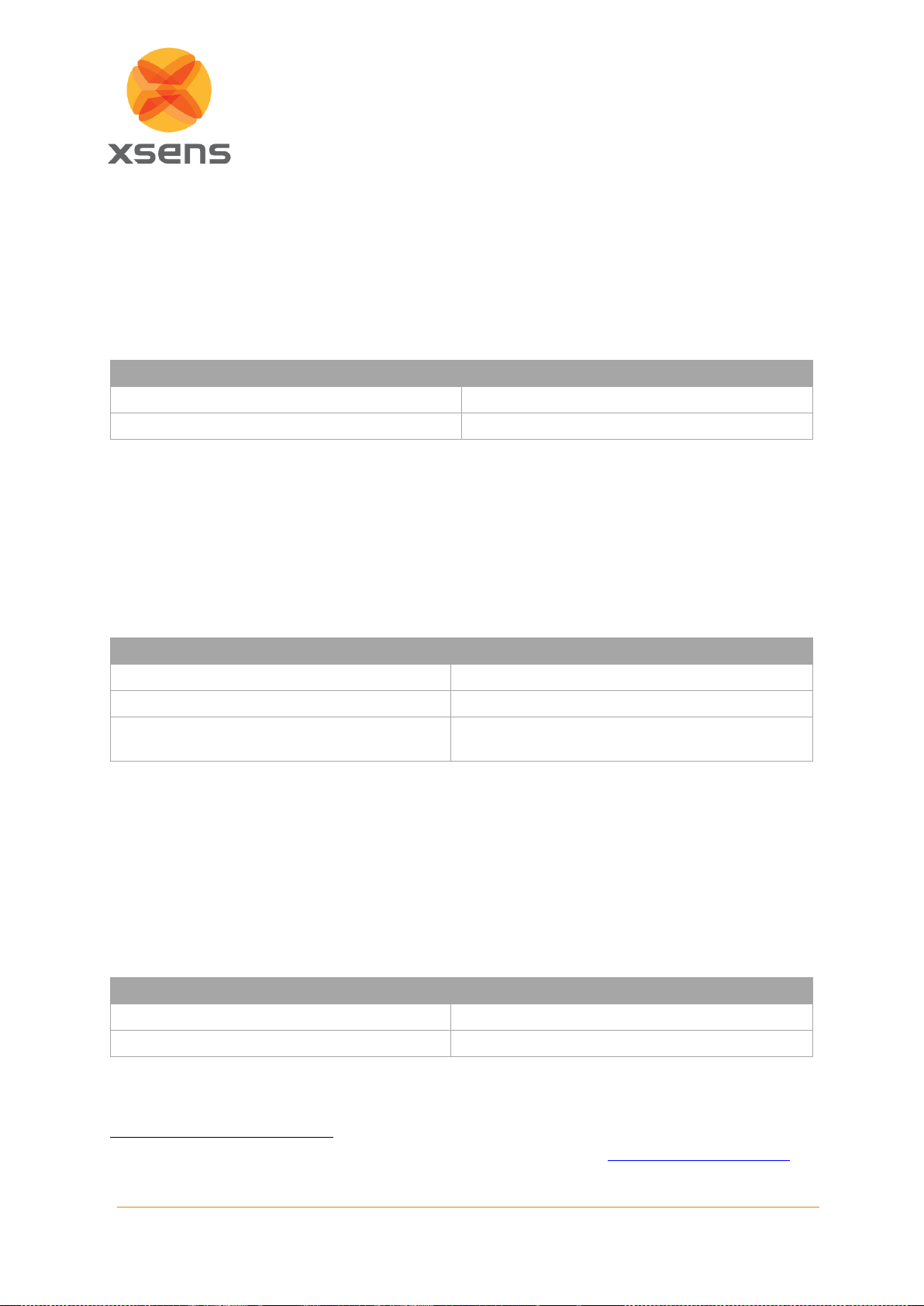
e.g. temperature. The basic model is linear and according to the following relation:
During factory calibration, to each MTi has been assigned a unique gain matrix, KT and the bias vector,
bT. This calibration data is used to relate the sampled digital voltages, u, from the sensors to the
respective physical quantity, s.
The gain matrix is split into a misalignment matrix, A, and a gain matrix, G. The misalignment specifies
the directions of the sensitive axes with respect to the ribs of the sensor-fixed coordinate system (S
xyz
)
housing. E.g. the first accelerometer misalignment matrix element a
1,x
describes the sensitive direction
of the accelerometer on channel one. The three sensitive directions are used to form the misalignment
matrix:
With O representing higher order models, temperature modelling, g-sensitivity corrections, etc.
Each individual MTi is modeled for temperature dependence of both gain and bias for all sensors and
other effects. This modeling is not represented by the simple model in the above equations but is
implemented in the firmware with the temperature coefficient being determined individually for each MTi
device during the calibration process. The basic indicative parameters in the above model of your
individual MTi can be found in MT Manager (Device Settings dialog).
9
The barometer and GNSS receiver do not require additional calibration.
Page 20
20
Document MT1600P.2019.A
© Xsens Technologies B.V.
MTi Family Reference Manual
4.3.1 Calibrated ∆q and ∆v outputs
The calibrated ∆q (delta_q) and ∆v (delta_v) outputs are the coning and sculling compensated
strapdown integrated data in the sensor-fixed coordinate system (S
xyz
) or (O
xyz
). Note that the value of
the output depends on the output frequency, as the values are integrated over the sample time. Delta_q
can also be noted as dq, delta_angle, del_q or OriInc. Delta_v can also be noted as dv, delta_velocity,
del_v or VelInc.
Table 8: Output specifications ∆q and ∆v outputs
Output
Unit
Delta_q (DataID 0x8030)
a.u. (quaternion values)
Delta_v (DataID 0x4010)
m/s
It is possible to multiply consecutive delta_q values to find the total orientation change over a specific
period. Note that this data is not drift free, it still contains the sensor bias, as it has not been processed
by the sensor fusion algorithm. Use the orientation output for drift free orientation.
4.3.2 Calibrated inertial and magnetic data outputs
Output of calibrated 3D linear acceleration, 3D rate of turn and 3D magnetic field data is in sensor-fixed
coordinate system (S
xyz
) or (O
xyz
). The units of the calibrated data output are as shown in Table 9.
Table 9: Output specifications inertial and magnetometer data outputs
Vector
Unit
Acceleration (DataID 0x4020)
m/s2
Angular velocity (RateOfTurn) (DataID 0x8020)
rad/s
Magnetic field (DataID 0xC020)
a.u. (arbitrary units; normalized to earth field
strength at the location the MFM is performed)
4.3.3 High-rate (HR) inertial data outputs
High-rate calibrated 3D acceleration (accelerometer) and 3D rate of turn (gyroscope) are outputted in
sensor-fixed coordinate system (S
xyz
) or (O
xyz
). The units of the calibrated data output are as shown in
Table 10. HR calibrated data is available at a higher rate than regular calibrated inertial data outputs. It
is outputted as a separate data packet next to the other data outputs. The maximum output rate, degree
of signal processing, and calibration applied depends on device type.
Refer to MT Low Level Communication Protocol Documentation10 for more details.
Table 10: Output specifications high rate calibrated inertial data outputs
Vector
Unit
AccelerationHR (DataID 0x4040)
m/s2
RateOfTurnHR (DataID 0x8040)
rad/s
10
Links to the latest available documentation can be found via the following link: Xsens MTi Documentation
Page 21

21
Document MT1600P.2019.A
© Xsens Technologies B.V.
MTi Family Reference Manual
4.3.4 Free acceleration
Free acceleration (Data ID 0x4030) is the acceleration in the local frame (L
XYZ
) from which the local
gravity is deducted. The output is in m/s2.
Page 22

22
Document MT1600P.2019.A
© Xsens Technologies B.V.
MTi Family Reference Manual
4.4 Xsens Sensor Fusion Algorithms
The orientation and position output of the VRU, AHRS and GNSS/INS are computed by Xsens’
proprietary sensor fusion algorithm. It uses signals of the rate gyroscopes, accelerometers,
magnetometers and optionally a GNSS receiver and barometer to compute a statistical optimal 3D
orientation and position estimates of high accuracy without drift for both static and dynamic movements.
The design of a typical algorithm can be summarized as a sensor fusion algorithm where the
measurement of gravity (by the 3D accelerometers) and Earth magnetic north (by the 3D
magnetometers) compensate for otherwise slowly, but unlimited, increasing (drift) errors from the
integration of rate of turn data (angular velocity from the rate gyroscope). This type of drift compensation
is often called attitude and heading referencing and such a system is referred to as an Attitude and
Heading Reference System (AHRS).
In products where a GNSS receiver is available, GNSS data is continuously used to aid the estimation
of the device’s roll, pitch and heading next to position and velocity. An additional benefit is that short
term GNSS outages can be coped with, through dead-reckoning, ensuring continuous data output. Such
a system is referred to as GNSS/INS.
4.4.1 Internal Sensor Bias Estimation
The Xsens algorithm continuously estimates the gyroscope bias. For the rate of turn around the x-axis
and the y-axis (roll and pitch axes), the gyroscope bias is estimated using gravity (accelerometers). In
a homogenous magnetic field and with filter profiles using the magnetometer, also the gyroscope bias
around the z-axis will successfully be estimated.
In some situations, the heading cannot be referenced to the (magnetic) north. This is the case when the
magnetic field is not used (for example for VRU devices) or when the magnetic field is distorted. There
are several ways to mitigate the drift in yaw (rotation around the z-axis):
1. When the MTi has sufficient movement in roll and pitch (>30 degrees for more than 10 seconds),
the gyroscope bias will be estimated for the z-gyroscope. When rotating the MTi back to roll and
pitch around 0 degrees, the yaw will be more stable than before the roll/pitch movements.
2. The yaw drift can also be stabilized by using Active Heading Stabilization (AHS). Refer to section
Error! Reference source not found. of this document for more details.
3. It is also possible to estimate the gyro bias using the manual gyro bias estimation when the MTi
does not rotate (also called no-rotation update). A tutorial of the Manual Gyro Bias Estimation
is available online through the following link: BASE by Xsens - Manual Gyro Bias Estimation
Tutorial
4.4.2 Roll and Pitch estimation
The Xsens sensor fusion algorithm stabilizes the inclination (i.e. roll and pitch combined) using the
accelerometer signals. An accelerometer measures the specific force that is composed of the
gravitational acceleration plus the linear acceleration due to the movement of the object with respect to
its surroundings. The algorithm uses the assumption that on average the acceleration due to the
movement is zero. Using this assumption, the direction of the gravity can be observed and used to
stabilize the attitude. The orientation of the MTi in the gravity field is accounted for such that centripetal
accelerations or asymmetrical movements cannot cause a degraded orientation estimate performance.
The key here is the amount of time over which the acceleration must be averaged for the assumption to
hold. During this time, the gyroscopes must be able to track the orientation to a high degree of accuracy.
In practice, this limits the amount of time over which the assumption holds true.
However, for some applications this assumption does not hold. For example, an accelerating automobile
may generate significant permanent accelerations for time periods lasting longer than the maximum
duration the MT’s rate gyroscopes can reliably keep track of the orientation. This may degrade the
Page 23

23
Document MT1600P.2019.A
© Xsens Technologies B.V.
MTi Family Reference Manual
accuracy of the orientation estimates because the application does not match the assumptions made in
the algorithm. Note however, that as soon as the movement again matches the assumptions made, the
algorithm will recover and stabilize. The recovery to optimal accuracy can take some time.
NOTE: To be able to accurately measure orientations as well as position in applications which can
encounter long-term accelerations we offer solutions that use aiding data from a GNSS receiver: the
MTi-7 GNSS/INS, MTi-670 GNSS/INS or MTi-G-710 GNSS/INS.
4.4.3 Heading/yaw estimation
By default, yaw is referenced by using the local (earth) magnetic field (e.g. in the AHRS product
versions). In other words, the measured magnetic field is used as a compass. If the local Earth magnetic
field is temporarily disturbed, the algorithm will track this disturbance instead of incorrectly assuming
there is not disturbance. However, in case of structural magnetic disturbance (>10 to 30 seconds,
depending on the filter profile settings) the computed heading will slowly converge to a solution using
the 'new' local magnetic north. Note that the magnetic field has not direct effect on the inclination
estimate.
The filter profile ‘Fixed Mag Ref’ will assume a magnetic reference upon startup and keep that reference
regardless of new magnetic environments (available only on MTi 600-series, see MTi 600-series
Datasheet).
In the special case the MTi is rigidly strapped to an object containing ferromagnetic materials, structural
magnetic disturbances will be present. In that case, Xsens offers an easy-to-use solutions to recalibrate
the magnetometers based on those structural magnetic disturbances (refer to chapter 6.3 of this
document.
Next to the solutions described on the article Estimating Yaw in magnetically disturbed environments to
mitigate effects from magnetic disturbances, the sensor fusion algorithm in a GNSS/INS device makes
use of data from the GNSS receiver. This means that the GNSS/INS device has an increased resistance
towards magnetic disturbances. It is for example possible to estimate the heading based on comparison
between accelerometer data and the GNSS acceleration. For GNSS/INS devices, the magnetometer
data is only actively used in the GeneralMag filter profile, the other filter profiles are completely
independent of the magnetic field.
4.4.4 Velocity and Position estimation
Transient accelerations
The GNSS/INS algorithm adds robustness to its orientation and position estimates by combining
measurements and estimates from the inertial sensors and GNSS receiver in order to compensate for
transient accelerations. It results in improved estimates of roll, pitch, yaw, position and velocity.
Loss of GNSS
When the GNSS/INS device has limited/mediocre GNSS reception or even no GNSS reception at all,
the sensor fusion algorithm seamlessly adjusts the filter settings in such a way that the highest possible
accuracy is maintained. The GNSS/INS MTi will continue to output position, velocity and orientation
estimates, although the accuracy is likely to degrade over time as the filters will have to rely on deadreckoning. The GNSS status will be monitored continuously such that the filter can take GNSS data into
account again when available and sufficiently trustworthy. In case the loss of GNSS lasts longer than a
specific period (depending on product type, e.g. 45 seconds), the device will enter a state in which it
stops outputting position and velocity estimates, and no longer uses velocity estimates in its sensor
fusion algorithms until GNSS reception is re-established.
Page 24
24
Document MT1600P.2019.A
© Xsens Technologies B.V.
MTi Family Reference Manual
4.4.5 Initialization
The Xsens sensor fusion algorithms do not only estimate orientation, but also keeps track of variables
such as sensor biases or properties of the local magnetic field. For this reason, the orientation output
may need some time to stabilize once the MTi is put into measurement mode. Time to obtain optimal
stable output depends on a number of factors. An important factor determining stabilizing time is
determined by the time to correct for small errors on the bias of the gyroscopes. The bias of the
gyroscope may slowly change due to different effect such as temperature change or exposure to impact.
4.4.6 Filter Profile options
As described above, the algorithm uses assumptions about the acceleration and the magnetic field to
obtain orientation. Because the characteristics of the acceleration or magnetic field differ for different
applications, the Xsens algorithm makes use of filter profiles to be able to use the correct assumptions
given the application. This way, it can be optimized for different types of movement. For optimal
performance in a given application, the correct filter profile must be set by the user. Each product offer
different filter profile options, refer to the specific documentation to know more about the filter profiles11.
4.4.7 Additional setting options and features
Table 11 summarizes the additional options offered to adapt and optimize the algorithm to cover more
scenarios and possible corner cases.
Table 11: Supplementary features and settings
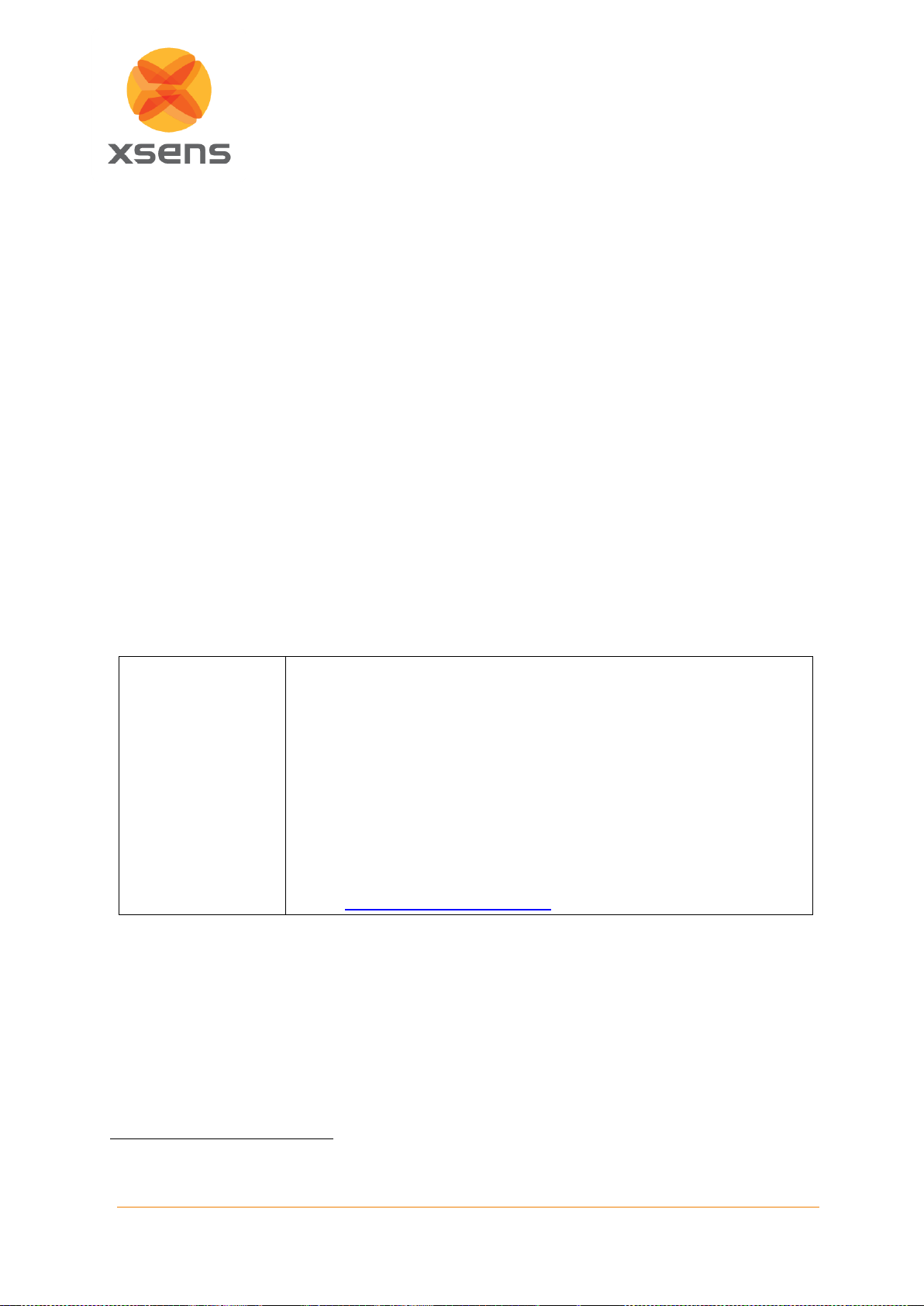
Active Heading
Stabilization (AHS)
Active Heading Stabilization (AHS) is a software component within the
sensor fusion engine designed to give a low-drift unreferenced (not Northreferenced) yaw solution even in a disturbed magnetic environment. It is
aimed to tackle magnetic distortions that do not move with the sensor, i.e.
temporary or spatial distortions.
AHS is not tuned for nor intended to be used with GNSS/INS devices.
Therefore, Xsens discourages the use of this feature for GNSS/INS
devices.
For the MTi 600-series, the AHS feature is embedded in the filter profiles.
For more information on the activation and use of AHS, refer to the BASEarticle: BASE by Xsens - AHS tutorial
11
Datasheet for the MTi 1-series and MTi 600-series. MTi User Manual for the other Xsens MTi products
Page 25

25
Document MT1600P.2019.A
© Xsens Technologies B.V.
MTi Family Reference Manual
Orientation
Smoother
The Orientation Smoother is a software component within the sensor fusion
engine that is currently only available for the MTi-G-710. This feature aims
to reduce any sudden jumps in the Orientation outputs that may arise when
fusing low-rate GNSS receiver messages with high-rate inertial sensor
data.
The Orientation Smoother can be enabled from the Device Settings window
in MT Manager, or by using the setOptionFlags low-level command (see
MT Low Level Communication Protocol Documentation12).
This feature is not yet available for the MTi 1-series or the MTi 600-series.
GNSS Platform
u-Blox GNSS receivers support different dynamic platform models in order
to adjust the navigation engine to the expected application environment.
The GNSS/INS products can be configured to communicate a desired
platform model upon start-up. This enables the user to adjust the u-Blox
receiver platform to match the dynamics of the application. The setting
influences the estimates of Position and Velocity and therefore it affects the
behavior of the Xsens filter output. Currently, only the Portable (default) and
Airborne (<4g) platforms are supported.
The platform model can be configured using MT Manager or low-level
communication. For more details on GNSS platform settings, refer to the uBlox Receiver Description Manual.
Alternatively, when using interfacing with a GNSS receiver through NMEA
communication, the received NMEA position data is used ‘as is’,
independent of the GNSS platform setting.
In-run Compass
Calibration (ICC)
In-run Compass Calibration (ICC) provides a solution to calibrate the
sensor for magnetic distortions caused by objects that move with the MTi.
Examples are the cases where the MTi is attached to a car, aircraft, ship or
other platforms that can distort the magnetic field. It also handles situations
in which the sensor has become magnetized. ICC is an alternative for the
offline MFM (Magnetic Field Mapper). It results in a solution that can run
embedded on different industrial platforms (leaving out the need for a host
processor like a PC) and relies less on specific user input.
ICC is currently a feature in beta. For more information, refer to the BASEarticle on ICC: BASE by Xsens - ICC Tutorial.
This feature is not yet available for the MTi 600-series.
12
Links to the latest available documentation can be found via the following link: Xsens MTi Documentation
Page 26

26
Document MT1600P.2019.A
© Xsens Technologies B.V.
MTi Family Reference Manual
4.5 MTi series interface options
The MTi series product lines are able to communicate and output data via many different interfaces.
Table 12 provides a convenient overview for the MTi 1-series and 600-series. Details on the interfaces
for each product are available in the respective datasheets or hardware integration manuals.
Table 12: overview of interface options in MTi portfolio
Interface
MTi 1-series
MTi-600-series
I²C
•
SPI
•
UART • •
USB
Development
Board
Development
Board or
UART2USB
Converter
RS232 •
RS485
RS422
Dev. Board
CAN •
4.6 Timing and synchronization
The MTi products support multiple features for synchronizing data with external devices and timing.
Please refer to the respective datasheets or manuals for more information.
Page 27

27
Document MT1600P.2019.A
© Xsens Technologies B.V.
MTi Family Reference Manual
5 Input and Output Specification
In this chapter the various output modes of the MTi are described. The MTi’s have several output
options. It is possible to select a different output frequency and/or output format (e.g. float or double)
per output or group of outputs. A full overview of the output options can be found in the MT Low Level
Communication Protocol Documentation13.
Performance specifications on orientation, position and sensor data can be found in the specific
datasheets of each MTi series.
5.1 Overview of data output protocols
The MTi supports different data protocols: the binary (hexadecimal) XBus protocol, NMEA (ASCII)
messages and CAN 2.0. Refer to MT Low Level Communication Protocol Documentation13 and MT
CAN Protocol Documentation to learn more about the structure of the protocols and how to switch
between them.
NOTE: The MTi 1-series only supports the binary XBus protocol.
5.2 Overview of data inputs
The MTi-670 requires GNSS receiver data to provide a full GNSS/INS solution. This can be achieved
by using the UBX protocol (uBlox proprietary protocol) or with NMEA input.
When connecting a uBlox receiver (e.g. uBlox MAX-M8), the MTi will configure it correctly on start-up.
No prior configuration of the uBlox receiver is required.
Alternatively, NMEA input (NMEAin) is a functionality that allows the input of data from an external GNSS
receiver using the NMEA protocol. As almost all GNSS receivers support the output of NMEA messages,
this functionality enables the use of virtually any GNSS receiver.
It is important to note that when using the NMEAin both the GNSS receiver and the MTi must be
configured prior to connecting both systems to each other. The NMEAin for the MTi-670 can be enabled
through an Xbus message called SetGnssReceiverSettings, described in the MT Low Level
Communication Protocol Documentation8. For the GNSS receiver settings, please review the MTi 600series Datasheet10.
The MTi-7 does not support NMEAin, please contact your sales representative for more information.
5.3 Built-in self-test
All MTi’s feature a built-in self-test (BIT). The self-test actuates the mechanical structures in the MEMS
accelerometer and gyroscope by inducing an electric signal. This allows checking the proper functioning
of the mechanical structures in the MEMS inertial sensors as well as the signal processing circuitry. For
the magnetometer, the self-test checks the integrity of the sensor component.
A passed self-test will result in a valid self-test flag in the status byte. Because the self-test influences
the sensor data, the self-test is only available in Config mode. For more information, look for RunSelftest
in MT Low Level Communication Protocol Documentation.
5.4 Timestamp and packet counter output
Each data message can be accompanied by a packet counter and/or timestamp. Refer to MT Low Level
Communication Protocol Documentation detailed information on the various time outputs.
13
Links to the latest available documentation can be found via the following link: Xsens MTi Documentation
Page 28

28
Document MT1600P.2019.A
© Xsens Technologies B.V.
MTi Family Reference Manual
5.5 Status word
The status word includes information about the status of the MTi, its sensors, the filter and user inputs.
Information contained within the status word are for example:
- Selftest
- Filter valid
- GNSS fix
- No rotation update status
- Representative motion
- Clip flags of all axis gyroscopes, accelerometers and magnetometers
- SyncIn / SyncOut
- Filter modes
Refer to MT Low Level Communication Protocol Documentation for detailed information on the Status
Word output.
Page 29

29
Document MT1600P.2019.A
© Xsens Technologies B.V.
MTi Family Reference Manual
6 Installation tips and tricks
6.1 Transient accelerations
The 3D linear accelerometers in the MTi are primarily used to estimate the direction of gravity to obtain
a reference for attitude (pitch/roll). During long periods (more than tens of seconds) of transient “free”
accelerations (i.e. 2nd derivative of position) the observation of gravity cannot be made. The sensor
fusion algorithms can mitigate these effects to a certain extent, but nonetheless it is impossible to
estimate true vertical without additional information.
The impact of transient accelerations can be minimized when you take into account a few things when
positioning the device when installing it in the object you want to track/navigate/stabilize or control.
If you want to use the MTi to measure the dynamics of a moving vehicle it is best to position the
measurement device at a position close to the centre of rotation (CR) of the vehicle/craft. Any rotations
around the centre of rotation translate into centripetal accelerations at any point outside the centr e of
rotation. For a GNSS/INS device with a valid GNSS-fix, the detrimental effect of transient accelerations
on orientation estimates is overcome by integrating GNSS measurements in the sensor fusion engine.
6.2 Vibrations
The MTi samples IMU signals at high frequency per channel, processing them using a strapdown
integration algorithm with coning/sculling compensation. Proper coning/sculling compensation already
mitigates errors that poorly designed signal processing pipelines introduce when the device is under
vibration. For best results however, it is recommended that the MTi be mechanically isolated from
vibrations as much as possible: since vibrations are measured directly by the accelerometers, the
following two conditions can make the readings from the accelerometers invalid;
1. The magnitude of the vibration is larger than the measurement range of the accelerometer. This
will cause the accelerometer to saturate, which may be observed as a “drift” in the zero-level of
the accelerometer. This will show up as an erroneous roll/pitch.
2. The frequency of the vibration is higher than the bandwidth of the accelerometer. In theory, such
vibrations are rejected, but in practice they can still give rise to aliasing, especially if close to the
bandwidth limit. This can be observed as a low frequency oscillation. Further, high frequency
vibrations often tend to have large acceleration amplitudes (see item 1).
There is an effect on the gyroscopes as well and especially when the vibrations include high-frequent
coning motion, the gyroscope readings may become invalid.
6.3 Magnetic materials and magnets
When an MTi is placed close to or on an object that is either magnetic or contains ferromagnetic
materials, the measured magnetic field is distorted (warped) and causes an error in the computed
heading. The earth magnetic field is altered by the presence of ferromagnetic materials, permanent
magnets or power lines with strong currents (several amperes) in the vicinity of the device. The distance
to the object and the amount of ferromagnetic material determines the magnitude of disturbance
introduced. Errors in estimated yaw due to such distortions can be quite large, since the earth magnetic
field is very weak in comparison to the magnitude of the sources of distortion.
By default, the AHRS and the GNSS/INS versions (when using the GeneralMag filter profile) stabilize
heading using the local Earth's magnetic field. In other words, the measured magnetic field is used as
a compass. In addition, the gyroscope biases are continuously estimated by the MTi's on-board filter.
For the rate of turn around the x-axis and the y-axis (roll and pitch axes), the gyroscope bias is estimated
Page 30

30
Document MT1600P.2019.A
© Xsens Technologies B.V.
MTi Family Reference Manual
using gravity (i.e. by using the accelerometers). In a homogeneous magnetic field, the gyroscope bias
around the z-axis can be successfully estimated as well by monitoring the direction of the magnetic field.
The magnetic field can be distorted by the presence of ferromagnetic materials, permanent magnets or
power lines with strong currents (several amperes) in the vicinity of the device. The distance to the object
and the amount of ferromagnetic material determines the magnitude of disturbance introduced. If the
local Earth magnetic field is temporarily disturbed, the on-board filters will initially track this disturbance
instead of incorrectly assuming that the device has rotated. However, in case of continuous magnetic
disturbances (>10 to 30 s, depending on the filter settings) the computed heading will slowly converge
to a new solution using the 'new' local magnetic north. Note that the magnetic field has no direct effect
on the inclination estimate.
In the special case that the MTi is rigidly strapped to an object containing ferromagnetic materials,
constant magnetic disturbances will be present. Using a so-called 'magnetic field mapping' (MFM, i.e. a
3D calibration for soft and hard iron effects), these magnetic disturbances can be completely calibrated
for, allowing the MTi to be used as if it would not be secured to the object containing ferromagnetic
materials.
For more information please review the Magnetic Calibration Manual14.
14
Links to the latest available documentation can be found via the following link: Xsens MTi Documentation
Page 31

31
Document MT1600P.2019.A
© Xsens Technologies B.V.
MTi Family Reference Manual
7 Warranty and liability
Xsens Technologies B.V. warrants the products manufactured by it to be free from defects in material
and workmanship for a period of two years from the date of delivery. Products not subjected to misuse
will be repaired, replaced or credit issued at the sole option of Xsens Technologies B.V. Contact Xsens
via www.xsens.com/support for return material authorization (RMA) prior to returning any items for
calibration, repair or exchange. The product must be returned in its original packaging to prevent
damage during shipping.
The warranty shall not apply to products repaired or altered or removed from the original casing by
others than Xsens Technologies B.V. so as, in Xsens Technologies B.V. opinion, to have adversely
affected the product, products subjected to negligence, accidents or damaged by circumstances beyond
Xsens Technologies B.V.’s control.
NOTE: Xsens reserves the right to make changes in its products in order to improve design,
performance, or reliability.
Subject to the conditions and limitations on liability stated herein, Xsens warrants that the Product as so
delivered shall materially conform to Xsens’ then current specifications for the Product, for a period of
one year from the date of delivery. ANY LIABILITY OF XSENS WITH RESPECT TO THE SYSTEM OR
THE PERFORMANCE THEREOF UNDER ANY WARRANTY, NEGLIGENCE, STRICT LIABILITY OR
OTHER THEORY WILL BE LIMITED EXCLUSIVELY TO PRODUCT REPAIR, REPLACEMENT OR, IF
REPLACEMENT IS INADEQUATE AS A REMEDY OR, IN XSENS' OPINION IMPRACTICAL, TO
REFUND THE PRICE PAID FOR THE PRODUCT. XSENS DOES NOT WARRANT, GUARANTEE, OR
MAKE ANY REPRESENTATIONS REGARDING THE USE, OR THE RESULTS OF THE USE, OF THE
PRODUCT OR WRITTEN MATERIALS IN TERMS OF CORRECTNESS, ACCURACY, RELIABILITY,
OR OTHERWISE. Xsens shall have no liability for delays or failures beyond its reasonable control.
7.1 Customer Support
Xsens is glad to help you with any questions you may have about the MTi, or about the use of the
technology for your application. The fastest way is Xsens’ Help Center, where engineers and other
Xsens users meet. Please visit this Help Center, contact Xsens’ distributor, or if you are a direct
customer of Xsens, our Customer Support:
➔ Online Help center: https://base.xsens.com
➔ Support page (firmware and software downloads): https://www.xsens.com/support/
➔ Distributor network: https://www.xsens.com/en/company-pages/company/distributors
➔ Telephone EMEA/Pacific: +31(0)88-9736700 (+31 88 XSENS 00)
➔ telephone US (Los Angeles, CA): +1 310-481-1800
To be able to help you, please mention your Motion Tracker Serial Number when requesting support.
 Loading...