

Page 1
®
VeriColor
Spectro
Non-Contact Spectrophotometer
Setup and Operator Manual
Page 2

Page 3
CE Declaration
Manufacturer's Name: X-Rite, Incorporated
Authorized Representative: X-Rite, Incorporated
Siemensstraße 12b
Phone:+49 (0) 61 02-79 57-0
Model Name: VeriColor Spectro
Model No.: VS410
Directive(s) Conformance: EMC 89/336/EEC LVD 73/23/EEC
Note:
This is a class A product. In a domestic environment this product may cause interference in which case
the user may be required to take adequate measures.
Federal Communications Commission Notice
NOTE: This equipment has been tested and found to comply with the limits for a Class A digital device,
pursuant to Part 15 of the FCC Rules. These limits are designed to provide reasonable protection
against harmful interference when the equipment is operated in a commercial environment. This
equipment generates, uses, and can radiate radio frequency energy and, if not installed and used in
accordance with the instruction manual, may cause harmful interference to radio communications.
Operation of this equipment in a residential area is likely to cause harmful interference in which case
the user will be required to correct the interference at his own expense.
VERICOLOR® SPECTRO
• 63263 Neu-Isenburg • Germany
• Fax: +49 (0) 61 02 -79 57-57
Industry Canada Compliance Statement
This Class A digital apparatus complies with Canadian ICES-003.
Cet appareil numérique de la classe A est conforme à la norme NMB-003 du Canada.
Equipment Information
Use of this equipment in a manner other than that specified by X-Rite, Incorporated may compromise
design integrity and become unsafe.
WARNING: This instrument is not for use in explosive environments.
ADVERTENCIA - NO use este aparato en los ambientes explosivos.
AVVERTIMENTO - NON usare questo apparecchio in ambienti esplosivi.
WARNUNG: Das Gerät darf in einer explosiven Umgebung NICHT verwendet werden.
AVERTISSEMENT: Cet instrument ne doit pas être utilisé dans un environnement explosif.
RoHS/WEEE
X-Rite products meet the Restriction of Hazardous Substances (RoHS) Directive 2002/95/EC and
European Union – Waste Electrical and Electronic Equipment (WEEE) Directive 2002/96/EC. Please
refer to www.xrite.com
for more information on X-Rite's compliance with the RoHS/WEEE directives.
3
Page 4

VERICOLOR® SPECTRO
Proprietary Notice
The information contained in this manual is derived from patent and proprietary data of
X-Rite, Incorporated. The contents of this manual are the property of X-Rite, Incorporated
and are copyrighted. Any reproduction in whole or part is strictly prohibited. Publication of
this information does not imply any rights to reproduce or use this manual for any purpose
other than installing, operating, or maintaining this instrument. No part of this manual may
be reproduced, transcribed, transmitted, stored in a retrieval system, or translated into any
language or computer language, in any form or by any means, electronic, magnetic,
mechanical, optical, manual, or otherwise, without the prior written permission of an officer
of X-Rite, Incorporated.
This product may be cover ed by one or more patents. Refer to the instrument for actual
patent numbers.
Copyright © 2007 by X-Rite, Incorporated “ALL RIGHTS RESERVED”
X-Rite and VeriColor are registered trademarks of X-Rite, Incorporated. All other logos, brand names, and product names mentioned
are the properties of their respective holders.
Warranty Information
X-Rite, Incorporated (“X-Rite”) warrants each instrument manufactured to be free of defects
in material and workmanship for a period of 12 months. This warranty shall be fulfilled by
the repair or replacement, at the option of X-Rite, of any part or parts, free of charge
including labor, F.O.B. its factory or authorized service center.
This warranty shall be voided by any repair, alteration, or modification, by persons other
than employees of X-Rite, or those expressly authorized by X-Rite to perform repairs, and by
any abuse, misuse, or neglect of the product, or by use not in accordance with X-Rite's
published instructions.
X-Rite reserves the right to make changes in design and /or improvements to its products
without any obligation to include these changes in any products previously manufactured.
Correction of defects by repair or replacement shall constitute fulfillment of all warranty
obligations on the part of X-Rite.
THIS WARRANTY IS EXPLICITLY IN LIEU OF ANY OTHER EXPRESSED OR IMPLIED
WARRANTIES, INCLUDING ANY IMPLIED WARRANTY OF MERCHANTABILITY OR FITNESS FOR
ANY PARTICULAR PURPOSE. THIS WARRANTY OBLIGATION IS LIMITED TO REPAIR OR
REPLACEMENT OF THE UNIT RETURNED TO X-RITE OR AN AUTHORIZED SERVICE CENTER
FOR THAT PURPOSE.
This agreement shall be interpreted in accordance with the laws of the State of Michigan and
jurisdiction and venue shall lie with the courts of Michigan as selected by X-Rite,
Incorporated.
4
Page 5

Table of Contents
VERICOLOR® SPECTRO
Overview 7
VeriColor Spectro Description 7
Unpacking and Inspection 7
VeriColor Spectro Installation 8
Measurement Distance 8
Height Insensitivity 9
Measurement Angle 9
VeriColor Spectro Dimension Drawing 10
Cable Connection and Wiring 11
Hardware Interface Description 13
Discrete Input Lines 13
Power/Comm/Control Cable (p/n: VCS50-EUR8-DB5) 13
Discrete Output Lines 14
Discrete Interface Cable (p/n: SE108-EUR8-5M) 16
Computer Interface 16
Status LED Indicator 17
Software Installation and Overview 18
Basic System Requirements 18
Installing the Software 18
Starting the Application 18
Application Overview 19
VeriColor Spectro System Operation 20
Configuring the Software Options 20
Administrative (Admin) Setup 20
Language Tool 26
Targeting a Part 27
Calibration/Verification of the VeriColor Spectro 28
Attaching the Calibration Tool 28
Performing Calibration (first time, out of box) 29
Performing Verification 30
Performing Calibration (after verification failure) 31
Calibration Configuration 32
Color Standards and Projects 34
Creating Palettes and Color Standards 34
Verify Mode 39
Project Mode 40
Configuration PLC Values 42
Monitor Mode 44
Selecting a Single Standard (no auto target) 44
Selecting a Project for Auto Targeting 45
Measuring a Standard 45
Setting Tolerances 46
Creating a Standard from a Series of Measurements 47
Manual Sample Measurement 47
Interval Sample Measurements 48
Viewing Sample Data 49
Lookup Mode 52
Compare Mode 54
Selecting a Standard from File 54
Measuring a Standard 55
Setting Tolerances 55
Selecting a Trial from file 56
Measuring a Trial 56
Deleting Trials 56
5
Page 6

VERICOLOR® SPECTRO
General Maintenance 58
Repair Information 58
Cleaning the Spectro Instrument Lenses 58
Cleaning the Calibration Tool 58
Hardware Troubleshooting 59
Appendices 61
Specifications 61
Accessories 62
Electrical Interface Details 63
6
Page 7
Overview
VeriColor Spectro Description
The VeriColor® Spectro is used to evaluate and identify colors in industrial applications. The
VeriColor Spectro is a spectrophotometer that delivers 100% in-line, non-contact, absolute
(L*a*b*) color measurement and identification.
Like other color sensors, the VeriColor Spectro allows you to “learn” (measure) standard
colors and measure samples for comparison. The system uses these comparisons to
determine the closest standard or pass/fail a sample based on a tolerance.
The system is composed of two main components: the VeriColor Spectro which stores
standard colors and captures sample color, and the software application.
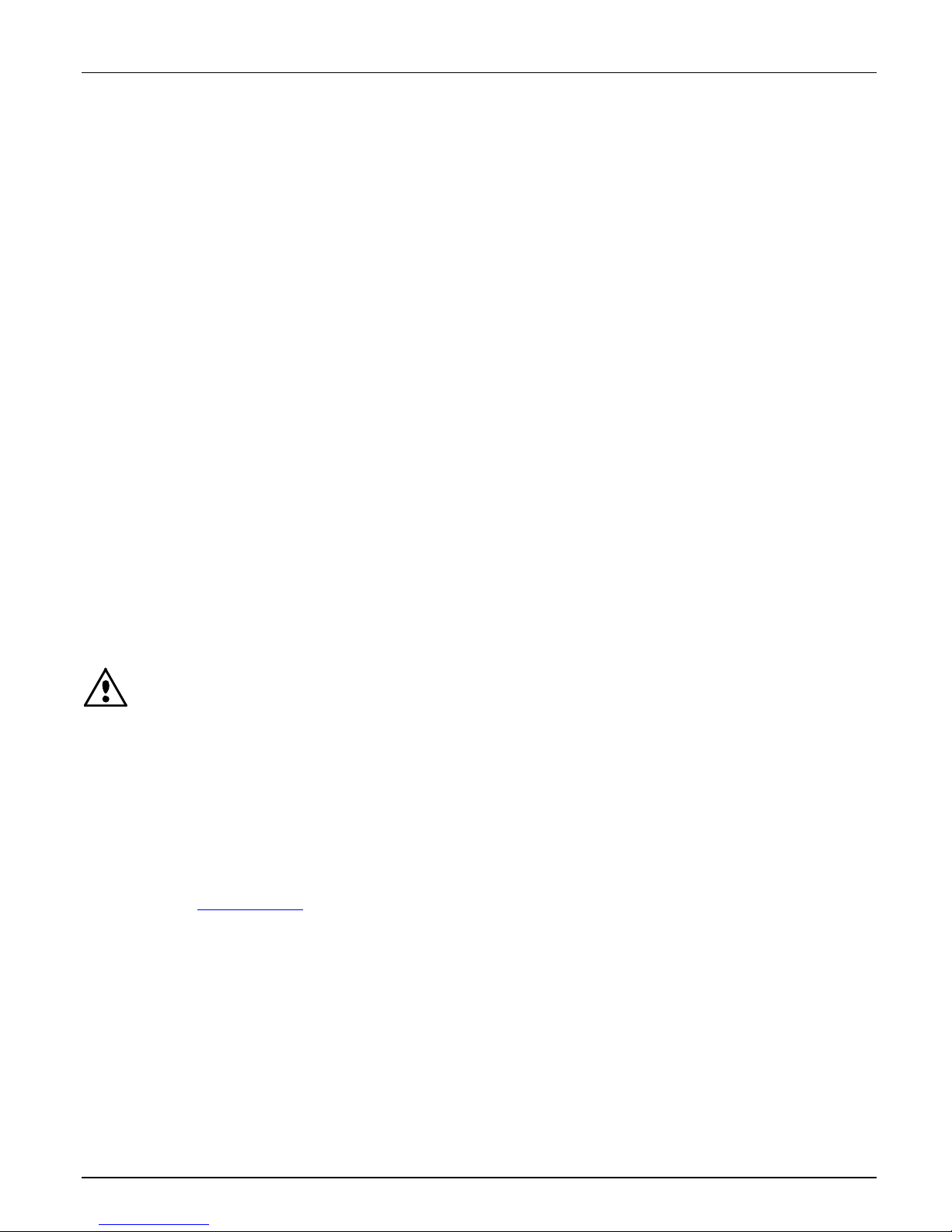
Sensor Lens
Illumination Lens
VERICOLOR® SPECTRO
Mounting Flange (4)
Unpacking and Inspection
After removing the VeriColor Spectro from the shipping carton, inspect it for damage. If any
damage has occurred during shipping, immediately contact the transportation company. Do
not proceed with installation until the carrier's agent has inspected the damage.
Your VeriColor Spectro was packaged in a specially designed carton to assure against
damage. If shipment is necessary, the VeriColor Spectro should be packaged in the original
carton along with all the accessories. If the original carton is not available, contact X-Rite to
have a replacement shipped to you.
Packaging Contents:
• VeriColor Spectro P/N VS410-00-01
• 5 Meter Male 8-Circuit Open Ended Cable P/N SE108-EUR8-5M
• 5 Meter Female 8-Circuit Open Ended P/N VCS50-EUR8-5DB
• Calibration Tool P/N VS410-63
• VeriColor Spectro Application Software CD P/N VS410-500-CD
• Setup and Operation Manual P/N VS410-500
• Registration Form (multi-language) P/N SD01-99
RS-232 Connector
RS-485 / PLC Connector
Status LED Indicator
7
Page 8
VERICOLOR® SPECTRO
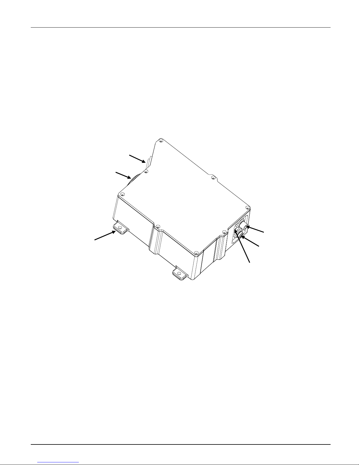
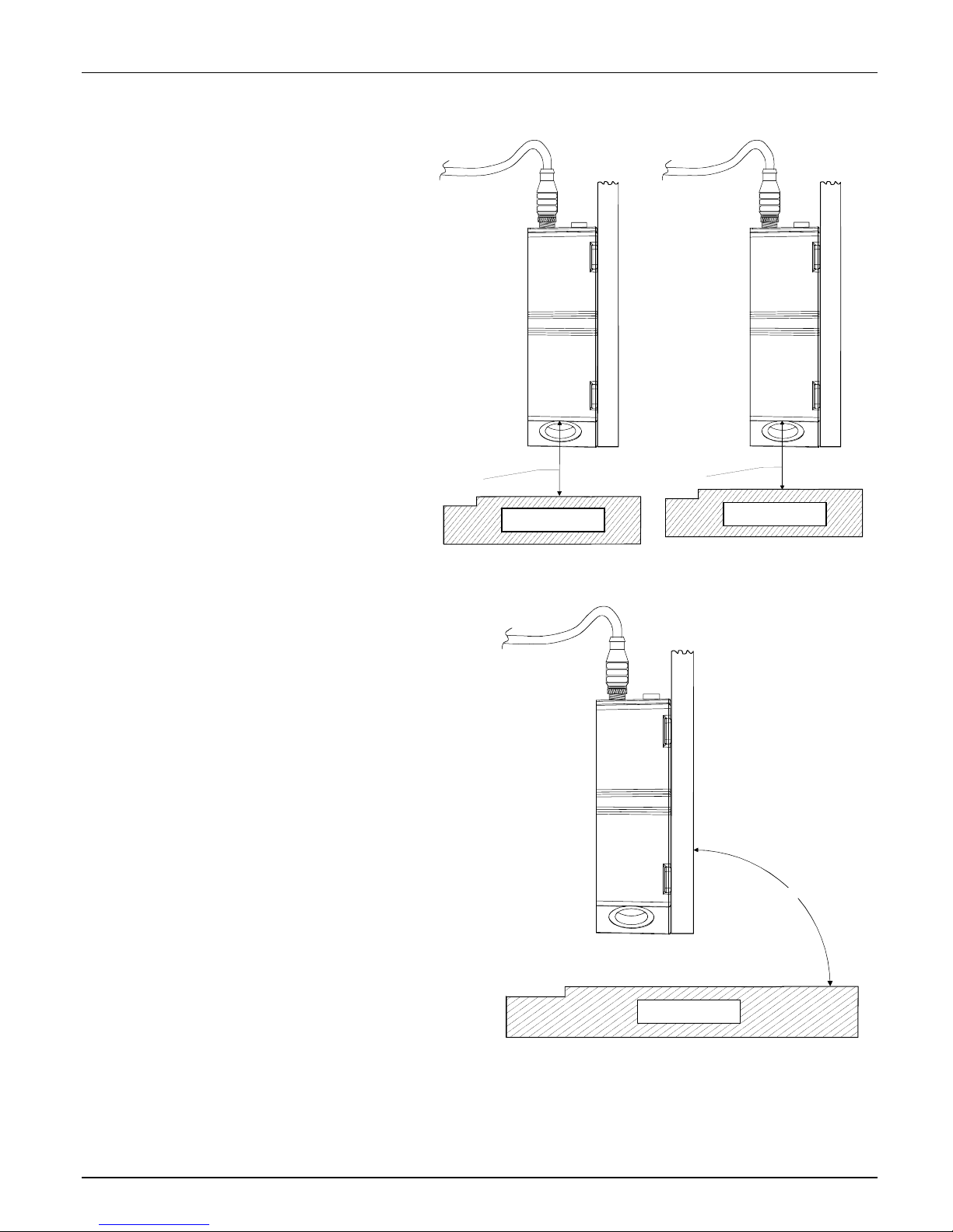
VeriColor Spectro Installation
Measurement Distance
Mount the VeriColor Spectro to the fixture using the holes provided at each flange.
VeriColor Spectro must be set to measure at a distance of 4” nominal to the measurement
surface. If the instrument is mounted in a 0°/30° geometry (preferred), the distance is that
from the center of the illumination lens to the sample. If the instrument is mounted in a
30°/0° geometry (alternate), the distance is measured from the center of the sensor lens to
the measurement surface.
CAUTION: Keep the sensor lens and illumination lens free from dust, smudge
marks, and finger prints.
0°/30° Mounting - Preferred 30°/0° Mounting - Alternate
Mounting
Flange (4)
Sensor Lens
Sample Part
Mounting
Flange (4)
Illumination Lens
4.0"
Sensor Lens
4.0"
Illumination Lens
Sample Part
IMPORTANT: The Geometry setting in the
software will require editing from the default
setting of “0°/30°” if the alternate 30°/0° mounting
method is used. Refer to the Calibration
Configuration section later in this manual for the
procedure.
8
Page 9
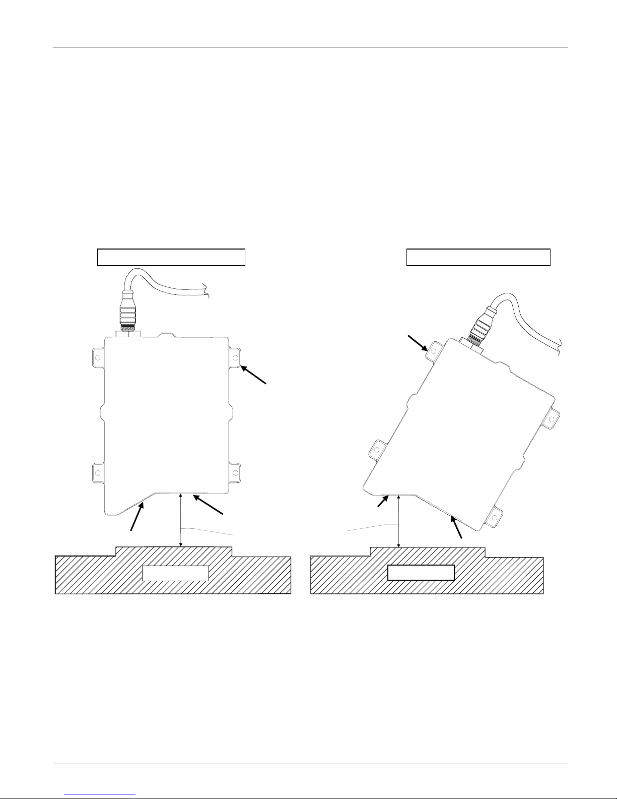
Height Insensitivity
Vericolor Spectro can tolerate
variation in depth of the
measurement distance of +/- 0.25”.
This means that if the sample being
measured fluctuates up and down
by no more than +/-0.25”, the
measurement will not be affected
beyond specified tolerances (refer
to the Specifications in the
Appendix). Any more than +/- 0.25”
it is suggested that the sample
being measured be stabilized to
prevent the variation in the
measurement distance.
VERICOLOR® SPECTRO
4.25"
Sample Part
3.75"
Sample Part
Measurement Angle
It is important when installing the
instrument in-line that the geometry and
axis angle be set appropriately. The
instrument can be set at a 0°/30°
illumination or 30°/0° illumination (see
illustrations on previous page). The 0°/30°
position is preferred for best repeatability
and correlation to an X-Rite 964 or similar
hand held spectrophotometer. Other angles
may be used (example 7.5/37.5) but care
must be taken to avoid sensing specular
reflections from the illuminator. Once the
instrument has been trained on a sample in
the preferred position, it is critical that
future samples be measured for comparison
against the standard at the same
measurement angle. Any deviation in the
measurement angle (called off axis
measurement) will affect the color reading
and indicate a fail condition, when in fact
the sample might be completely within the
specified tolerance range.
It is preferred that the instruments
mounting plane be as close to 90° to
sample plane as possible.
It is recommended that once the mounting angle of measurement is determined, the
instrument fixed position should be marked or documented. This will allow you to more easily
reposition the instrument to the original and correct position when measuring that sample
profile and color.
90°
Sample Part
9
Page 10
VERICOLOR® SPECTRO
(
)
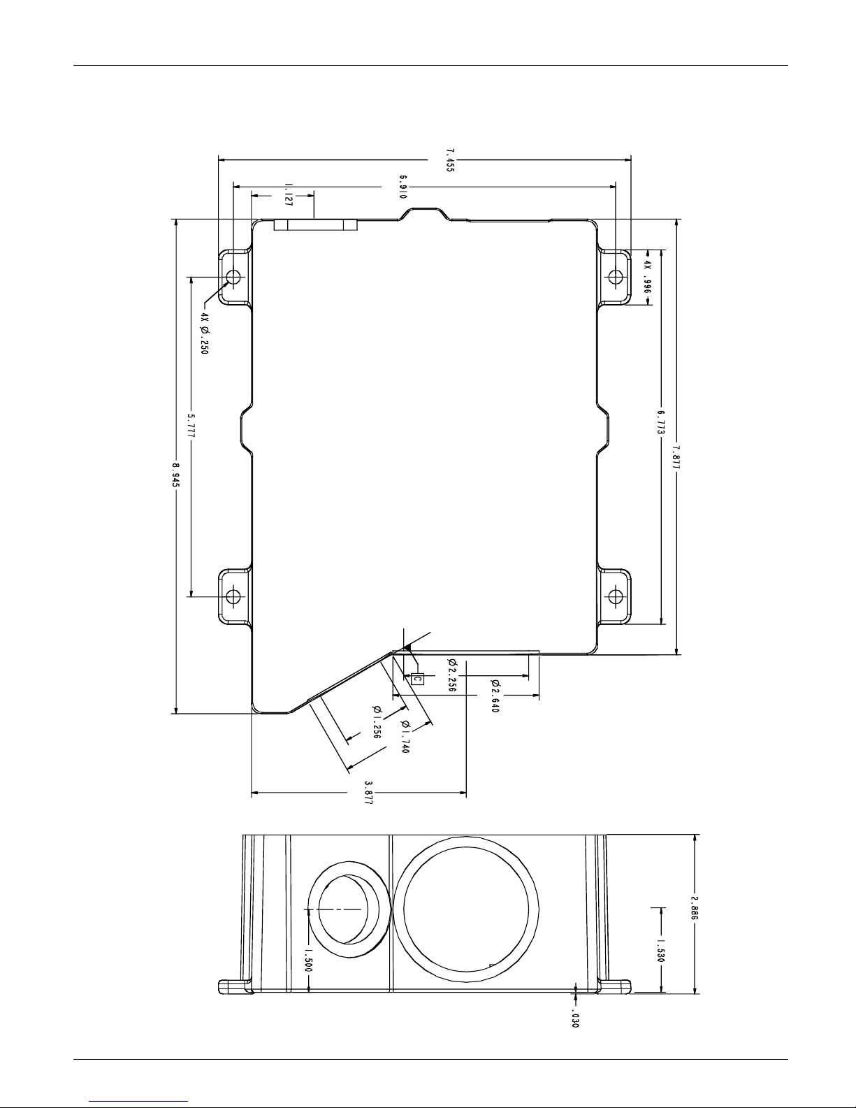
VeriColor Spectro Dimension Drawing
(189.35 mm)
227.20 mm
(28.62 mm)
(6.35 mm)
(146.73 m m )
(175.51 mm)
(25.29 mm)
(172.03 mm)
(200.07 mm)
(57.30 mm)
(67.05 mm)
(31.90 mm)
(44.19 mm)
(98.47 mm)
(73.30 mm)
(38.10 mm)
(0.76 mm)
(38.86 mm)
10
Page 11
Cable Connection and Wiring
The VeriColor Spectro is designed to utilize the same cable configuration as the VeriColor
Solo; however, due to the increased power requirements of the VeriColor Spectro, RS232
communication should be limited to cable lengths of less than 15 meters. For cable distances
longer than 15 meters it is recommended that the RS485 communication scheme be utilized.
The VeriColor Spectro RS485 communications wiring may be configured as either half or full
duplex on a single drop RS485 line. Usage of the RS485 communication requires proper
ground termination for both the power supply cable and the RS485 cable; any notable
differences in potential between the cable grounds may result in intermittent communication,
communication failure and possible damage to the instrument.
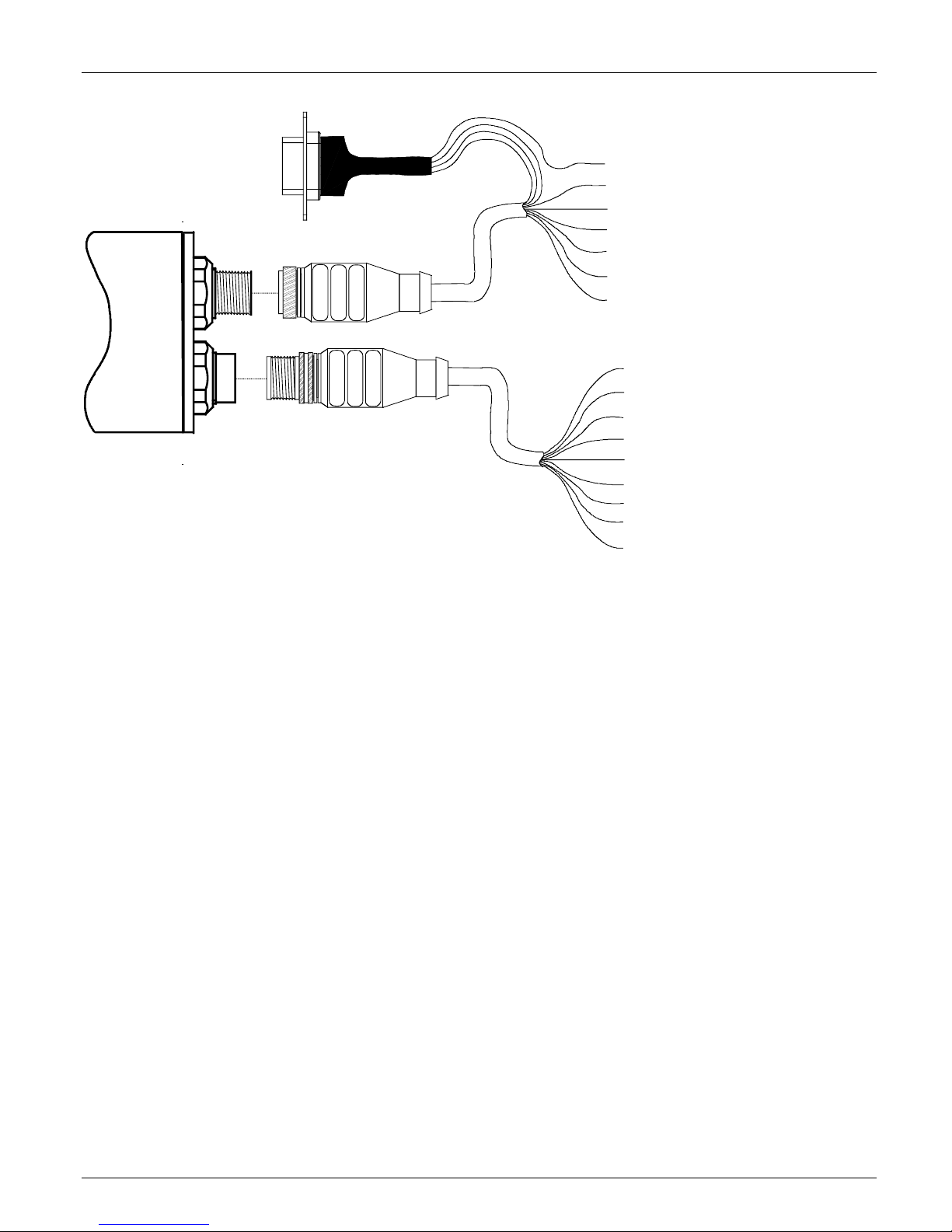
1. After the instrument has been mounted, attach the female connector of the
'Power/Comm/Control' cable (p/n: VCS50-EUR8-5DB) to the male connector (longer,
threaded), located on the back end of the VeriColor Spectro, and tighten.
2. The other end of this cable has a DB9 connector and several stripped and tined wires.
This end interface to power, computer and discrete devices.
a. Instrument power is applied via the white (+) and brown (-) wires (+24 Vdc ±2 Vdc)
IMPORTANT: A limited current source must be used. The applied operational power
shall be a filtered +24 Vdc, ±2 Vdc tolerance, having a 3-Amp capacity.
b. RS232 communications is obtained via the pre-wired DB9 connector.
c. If manual or discrete operation is needed, attach the appropriate wires to controlling
device (relay, PLC terminal, etc.). These lines are the READ, 10's, 1's, and DSR inputs
and are low-power, active high inputs. Refer to next section for details.
3. If discrete output, PLC feedback or RS485 interfacing is needed, attach and tighten the
male connector of the 'Discrete Interface' cable (p/n: SE108-EUR8-5M) to the female
connector (short, non-threaded). The connector is located on the back of the VeriColor
Spectro instrument.
4. The other end of this cable has several stripped and tined wires allowing low power
interface to discrete devices and/or attachment to an RS485 port (4-wire).
a. 'Pass', 'Fail', 'Action' and 4 discrete channels are the default output signal set-up.
b. Optional RS485 control (communications) is set-up by changing the 4 discrete
channels.
c. Attach the appropriate wires to the controlling device (relay, PLC terminal, etc.).
These outputs all use a common feed or return line. Refer to next section for details.
5. See the diagrams on the next several pages and appendices for electrical interface details
plus examples.
VERICOLOR® SPECTRO
11
Page 12
VERICOLOR® SPECTRO
DB9 Connector
Pin 5 – #2 Ground (brown)
Pin 2 – #3 Txout (green)
Pin 3 – #4 Rvin (yellow)
Power/Comm/Control Cable
(VCS50-EUR8-5DB)
#2 – Negative (brown)
#1 - +24 Vdc (white)
#5 – DSR (gray)
#6 – 10's (pink)
#7 – 1's (blue)
#8 – READ (red)
Cable Shield (Panel or fixture ground)
Discrete Interface Cable
(SE108-EUR8-5M)
#1 – PASS (white)
#2 – FAIL (brown)
#3 – Output Comm (green)
#4 – CH-E 16 / 'ACTION' (yellow)
#5 – CH-D 8 / RS485-TX-A (gray)*
#6 – CH-C 4 / RS485-RX-A (pink)*
#7 – CH-B 2 / RS485-RX-B (blue)*
#8 – CH-A 1 / RS485-TX-B (red)*
Cable Shield**
*Connect the “#5 – CH-D 8 / RS485-TX-A (gray)” and “#6 – CH-C 4 / RS485-RX-A (pink)” wires together for
Half Duplex. Also, connect the “#7 - CH-B 2 / RS485-RX-B (blue)” and “#8 – CH-A 1 / RS485-TX-B (red)”
wires together for Half Duplex.
**Use as common return to controller ground (insert a 10Ω resistor if voltage potential between the controller
and VeriColor Spectro is significant).
12
Page 13

Hardware Interface Description
The VeriColor Spectro interconnects externally using serial communications and/or discrete
signals to a computer or programmable device; detailed as follows. Additionally, there is a
visual indicator which provides system status during set-up or local maintenance monitoring.
Refer to the appendices for electrical interface details and examples.
Discrete Input Lines
These control lines are part of the 'Power/Comm/Control' cable and are low power, active
high inputs, as referenced to the ground return power supply input. Each input has an on/off
timing cycle which creates the signal that the VeriColor Spectro recognizes and then takes a
responsive action.
The active high condition means to initiate an action utilizing a positive voltage signal (+9Vdc
to +24Vdc) for a specific time period. The time period is typically 65 milli-seconds, ±15 milliseconds in duration. The 'Discrete Select Request' (DSR) has longer special conditions that
are explained later.
Power/Comm/Control Cable (p/n: VCS50-EUR8-DB5)
Discrete Select Request (DSR) – gray wire
This input is used to prompt the selection of a different color standard before the next
measurement is taken. It is the control input (request) that allows the toggling of the 1's and
10's input, so it must be activated first.
VERICOLOR® SPECTRO
During the activation of DSR, new measurement triggers are locked out (ignored) until DSR
is completed. Each time DSR is enabled, the color number selection starts at 0 (zero) and
increments according to the 1's and 10's toggling. After the new color number has been
selected, when DSR is completed, the new color number is stored. If the DSR input is
released without changing the color number (toggling the 1's or 10's), the color number
remains at the previous stored value.
There is a maximum of 250 colors that can be stored and therefore selected.
Due to the requirement that this input remain on (active) while the 1's and 10's are toggled,
the time duration or period is dependent on the number of those 1 and 10 activations
combined.
1's Select – blue wire
This input can only be used while DSR is active.
Each time this input is toggled the color number will increment by 1.
This input can be used at the same time as the 10's input, so it should only toggle a
maximum of 9 times to prevent selection errors.
10's Select – pink wire
This input can only be used while DSR is active.
Each time this input is toggled the color number will increment by 10.
This input can be used at the same time as the 1's input, so it should only toggle a maximum
of 24 times to prevent selection errors (i.e. 24 toggles times 10 is 240 and added with 9
ones is 249).
13
Page 14
VERICOLOR® SPECTRO
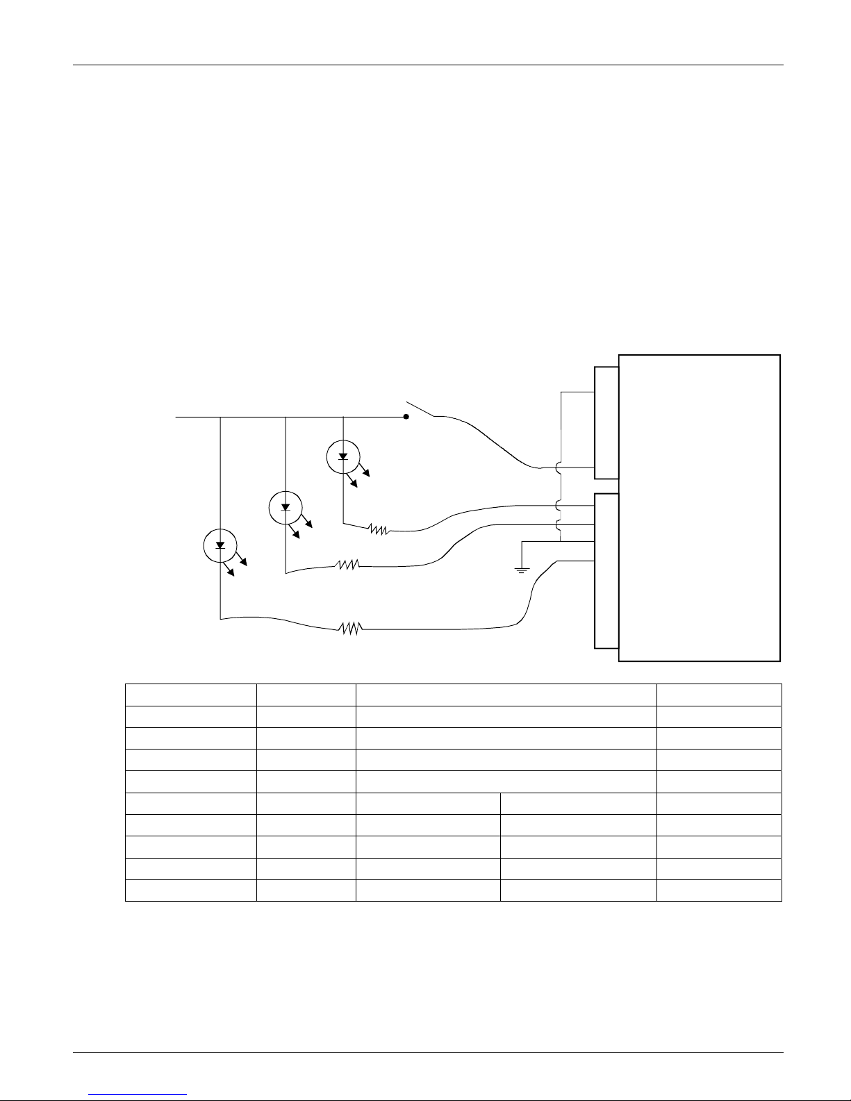
Discrete Output Lines
These individual signal lines are part of the 'Discrete Interface' cable and all are low power
outputs which use a common control line referenced (“ComO”; the green wire). This common
line is either a supply or ground return connection for these outputs.
a. Low power means these outputs are intended for +9Vdc min to +24Vdc max @ 120 mA.
Refer to Electrical Interface Details in the Appendix for additional information.
b. All outputs default as normally open contacts, but can be configured as to normally
closed contacts. Note they still all use a common control line.
c. If the common control line is connected to ground, then all outputs are in low-side or
return path configuration. This means when VeriColor Spectro activates the 'pass' output,
it is providing a ground return for an external light or relay coil to turn on. See Figure 1.
Discrete I/O Connections (Example: Low-side output enable)
+24 Vdc
read
brn
2
Pwr & RS232
J1
male 8-pin
red
8
Pass
Rx
Fail
Action
Rx = current limiting resisto r as nee ded
Rx
Rx
Connector J2 Color Description
Pin 1 White PASS = pass result Output
Pin 2 Brown FAIL = fail result Output
Pin 3 Green ComO = common discrete outputs Output
Pin 4 Yellow CH-E = 'ACTION' result Output
Instrument Outside Control
Pin 5 Gray TXD A RXD A Output
Pin 6 Pink RXD A TXD A Output
Pin 7 Blue RXD B TXD B Output
Pin 8 Red TXD B RXD B Output
A (-) B (+)
wht
brn
grn
yel
nu
nu
nu
nu
1
2
3
4
5
6
7
8
VC Spectro
nu = not used
J2
Discrete I/O
female 8-pin
d. If the common is connected to power (voltage ranging from +9Vdc to +24Vdc), then all
outputs are in high-side or supply path configuration. This means when VeriColor Spectro
activates the 'pass' output it is providing a positive voltage signal for an external light or
relay coil to turn on. See figure 2 on the next page.
14
Figure 1
Page 15
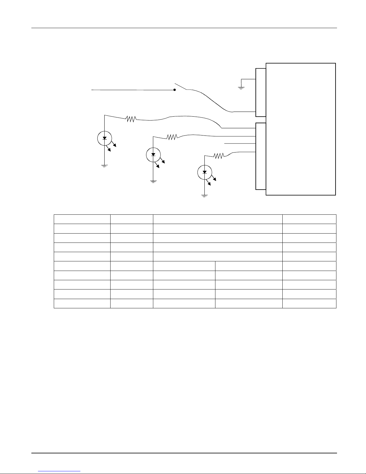
Discrete I/O Connections (Example: High-side output enable)
VERICOLOR® SPECTRO
+24 Vdc
read
brn
2
J1
Pwr & RS232
male 8-pin
red
8
Rx
Rx
Pass
Fail
Rx = current limiting resisto r as nee ded
+24 Vdc
Rx
Action
Connector J2 Color Description
Pin 1 White PASS = pass result Output
Pin 2 Brown FAIL = fail result Output
Pin 3 Green ComO = common discrete outputs Output
Pin 4 Yellow CH-E = 'ACTION' result Output
Instrument Outside Control
Pin 5 Gray TXD A RXD A Output
Pin 6 Pink RXD A TXD A Output
Pin 7 Blue RXD B TXD B Output
Pin 8 Red TXD B RXD B Output
A (-) B (+)
wht
brn
grn
yel
nu
nu
nu
nu
1
2
3
4
5
6
7
8
VC Spectro
nu = not used
J2
Discrete I/O
female 8-pin
In the default project set-up these wires are all discrete lines. Pass, Fail and ComO are
always the same, while CH-A through CH-D and Action can have an alternate configuration.
a. Action is the default but can be configured as CH-E (channel-E).
b. CH-A through CH-D are the defaults but can be configured into a 4-wire RS485 port.
Once these lines are set as RS485, they cannot also be used as discrete outputs.
Figure 2
15
Page 16

VERICOLOR® SPECTRO
Discrete Interface Cable (p/n: SE108-EUR8-5M)
Pass – white wire
This output is a VeriColor Spectro measurement response. It is activated when the last
sample was determined to be within the set tolerance for the selected color.
Fail – brown wire
This output is a VeriColor Spectro measurement response. It is activated when the last
sample was determined to NOT be within the set tolerance for the selected color, or had a
greater difference than allowed for the selected color.
Action – yellow wire
In the default set-up state 'Action', this output activates to a VeriColor Spectro measurement
response. It is activated when the last sample was determined to be within the set tolerance
for the selected color, but is either very close to being out of tolerance or is statistically
trending toward the limits.
However, if configured as a discrete channel output 'CH-E', then its activation will depend on
how the user has determined what this output is used as (project set-up conditions).
CH-A through CH-D / RS485
In the default set-up state 'CH-A through CH-D', these outputs activate to a VeriColor
Spectro measurement response. Their activation will depend on how the user has
determined what this output is used as (project set-up). They can be individual control lines
or a group output (binary/HEX).
However, if configured as an RS485, 4-wire port, then only RS485 operation is allowed.
• CH-A / RS-485-Tx-A - red wire
• CH-B / RS-485-Rv-A - blue wire
• CH-C / RS-485-Rv-B - pink wire
• CH-D / RS-485-Tx-B - gray wire
NOTE: Connect the “CH-A / RS-485-Tx-A - red wire” and “CH-B / RS-485-Rv-A - blue wire”
together for Half Duplex. Also, connect the “CH-C / RS-485-Rv-B - pink wire” and “CH-D /
RS-485-Tx-B - gray wire” together for Half Duplex.
Computer Interface
Normal computer communications between the user and the VeriColor Spectro is by the
serial RS232 interface. This interface is part of the 'Power/Comm/Control' cable, which has a
DB9 connector pre-wired for this feature. The VeriColor Spectro can also be configured to
communicate using RS485, if the appropriate discrete outputs are project set-up to operate
in this mode. Other communication schemes can be utilized if an external adapter is attached
(see note on RS232 to RS485 Adaptors below).
Note: On the Use of RS232 to RS485 Adaptors
While RS232 to RS485 adaptors are common and relatively inexpensive, the use of such
adaptors can be problematic in half duplex operation. For example, many such adaptors do
not have adequate power resources to generate currents for the longer periods of time
necessary when operating at low baud rates into terminated lines. Furthermore, until
recently, adaptors did not have the intelligence to know when to hold or release the transmit
condition. Often, a delay was inserted to hold the transmit condition until it was thought that
no more characters were coming through the RS232 interface. This delay was accomplished
with a simple timer that required the user to change a resistor in the adaptor to select the
right delay for the right baud rate. This meant that any requirements that differed from the
adaptor's default state would require the operator to “tweak” hardware or configuration
jumpers until things began to work properly.
16
Page 17

VERICOLOR® SPECTRO
X-Rite recommends the use of PCI to RS485 adaptors for installations where a PC is the
controlling device. These adaptors are usually free from the limitations previously mentioned,
may provide features that simply are not available in other adaptor designs, and are cost
effective. Ethernet to RS485 and USB to RS485 adaptors are also available, and while these
types may be ideal for a given installation, they usually have fewer configuration options.
Important: The VeriColorSpectro does NOT support simultaneous communication over
RS232 and RS485. Response should be finished before attempting to use the other port.
RS232 Interface
The default computer communications is by way of the serial RS232 interface which is part of
the 'Power/Comm/Control' cable, via a DB9 connector.
The communications protocol is serial using X-Rite's RCI command set. See appropriate
documentation for this command set.
Status LED Indicator
On the back plate of the VeriColor Spectro, located between the 2 rear mounted connectors,
is a LED indicator which visually provides system status. This LED indicator is capable of
displaying three colors: green, amber and red. A description of each color status is listed
below.
Off (no color) – This generally indicates the VeriColor Spectro has no power.
Solid Green – indicates the VeriColor Spectro is ready and waiting for further input (discrete
input or serial port).
Solid Amber – indicates the VeriColor Spectro is busy and performing a requested task.
Whenever a PLC input or serial command is being processed, the status light should remain
amber until it is ready for the next request.
Solid Red – indicates system error/failure. If this occurs then the VeriColor Spectro is not
functioning and cannot be used until the problem is resolved.
Flashing Amber – When the VeriColor Spectro is first powered up, it will slowly flash while
undergoing system test, and waiting for the illumination LED pack to warm up to
temperature.
Flashing Red – Indicates that the VeriColor Spectro is above operating temperature and will
shut down shortly.
Flashing Green – Indicates that the red LED has burned out and the yellow light is non
operable.
17
Page 18
VERICOLOR® SPECTRO
Software Installation and Overview
The VeriColor Spectro system includes a software application that provides an interface for
the VeriColor Spectro. The application is used to configure the VeriColor Spectro, store
projects which consist of color standards, and provide visual feedback of sample
measurements.
Before installing the software, make sure the VeriColor Spectro is set up as explained earlier
and the cable is connected to appropriate communication port.
Basic System Requirements
• Windows 2000 or XP Pro
• Minimum Screen resolution (1024 x 768)
Installing the Software
The software uses a standard Windows installation procedure.
1. Insert the software CD into your computer's CD-ROM drive. Browse to the Application
folder and double-click the setup.exe file on the CD.
2. The setup program guides you through the rest of the installation process. Follow the
instructions on each setup screen to complete the installation.
Starting the Application
The software application can be launched using the “VeriColor Spectro” short-cut on the
desktop or from within the Programs> VeriColor Spectro application group.
NOTE: If the VeriColor Spectro is not connected to COM 1, you will need to select the correct
communications port after launching the application for the first time. Click Admin and
select the General page to set correct COM port. Refer to Configuring the Software Options
later in this section for additional information. After the correct port is selected, you will need
to perform a calibration. Please refer to the Calibration procedure in the System Operation
section for additional information.
18
Page 19
VERICOLOR® SPECTRO
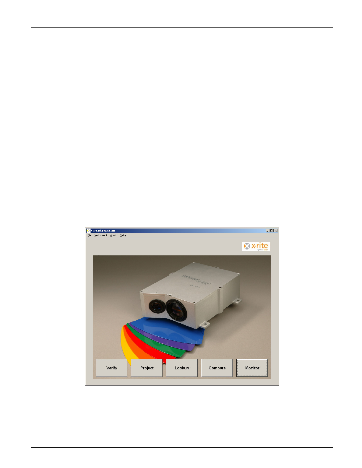
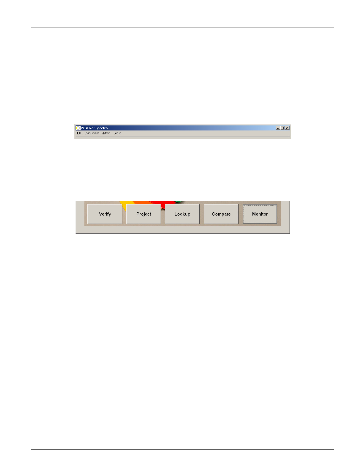
Application Overview
The VeriColor Spectro application consists of four menus and five application modes. The
menus are located at the top and the mode bottoms are at the bottom of the application.
Menus
• File – used to exit the application and launch a language translation tool (if activated
in Admin)
• Instrument – used for testing, calibrating and targeting of the VeriColor Spectro
• Admin – used to configure the default settings for the application
• Setup - used to create palettes and standards
Application Modes
• Verify – used to find the closest stored standard to a measured sample
• Project – used to create projects
• Lookup – used to auto select a standard from a palette
• Compare – used to compare stored or measured trial and standard data
• Monitor - used to monitor sample measurements after the system is set up
Refer to the VeriColor System Operation section that follows for detailed information on
setting up the software and using the VeriColor Spectro with the software application.
19
Page 20
VERICOLOR® SPECTRO
VeriColor Spectro System Operation
Configuring the Software Options
The software should be configured before proceeding with the color standards setup and
sample measurements.
Administrative (Admin) Setup
Administrative setup is used to configure the General, Verify, Lookup, Compare, and Monitor
options. The Admin dialog is accessed by clicking Admin menu at the top of the application.
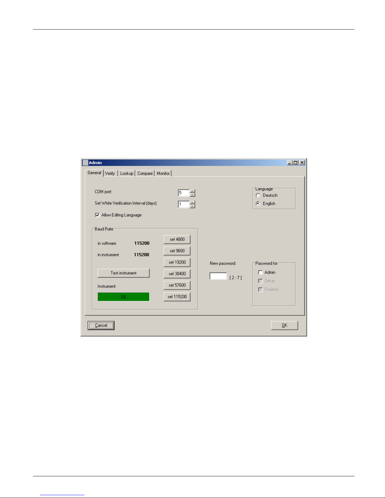
General Screen Page
The general screen is used to establish serial communications, select the language the
application will run in, and setup password protection.
1. Click in the COM port field and enter an appropriate port number, or use the up/down
arrows to select the connection port. The default port is one.
2. Click in the Set White Verification … field and select the number of days that pass
before you would like to be reminded to perform a verification. Use the up/down arrows
to select the number of days, ranging from 1 to 30. The default number is 1.
3. Click one of the Baud Rate buttons to select the desired baud rate. Once selected, the
instrument and software will both be configured. The default baud rate is 115200. You
can click the Test instrument button to check the baud rate selected. If the connection
is fine, OK should appear in a green box below the instrument field.
4. Select the Language that you would like that application to run in by clicking the
appropriate option. The default language is set to English. If the desired language is not
available, you can use the Language Tool option located in the File menu to localize the
application to a different language. Refer to the Language Tool later in this section.
NOTE: The Allow Editing Language option must be checked before the Language Tool
item appears in the File menu. The default is un-checked.
20
Page 21
VERICOLOR® SPECTRO
5. You can password protect the Admin menu, Setup menu, and Project mode from
unauthorized access by checking the desired Password for option and entering a
password in the New password field. The password must be between 2 and 7 characters
to be acceptable. You will then be asked to enter this password before you can access the
mode selected.
6. Click the OK button to save your setting and exit Admin; or select the Verify, Lookup,
Compare, or Monitor page to continue with option settings.
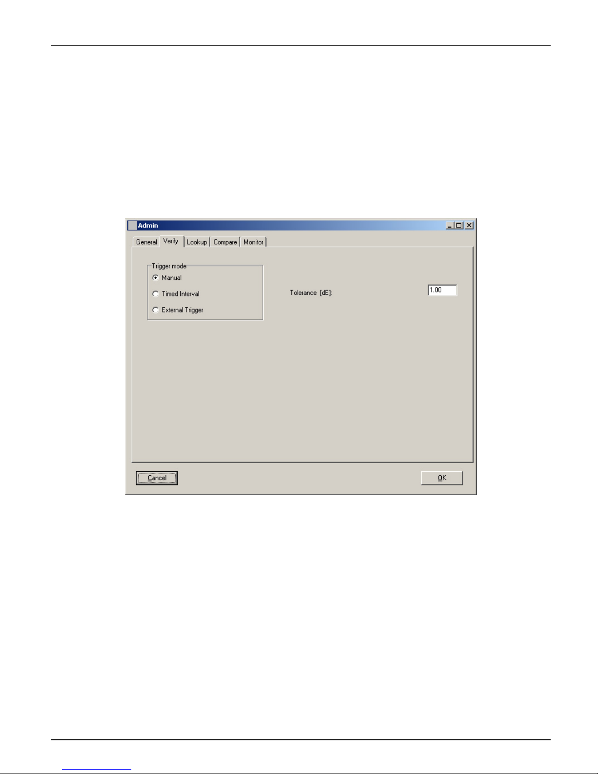
Verify Screen Page
The verify screen is used to choose how the measurement will be triggered, measurement
interval time (for timed interval), and the Tolerance dE value used for Verify mode.
1. Select Manual, Timed interval, or External Trigger as the trigger mode. This
determines the measurement method that is used in Verify mode. The default mode is
Timed interval. Manual selection requires a Measure button click for each measurement.
Timed interval allows automatic interval measurements to take place. External trigging
requires an external device (PLC) to activate a measurement.
2. Click in the Tolerance dE field and enter desired tolerance value. This determines the dE
value used in the Verify mode.
3. Click the OK button to save your setting and exit Admin; or select the General, Lookup,
Compare, or Monitor page to continue with option settings.
21
Page 22

VERICOLOR® SPECTRO
Lookup Screen Page
The lookup screen is used to enter the Tolerance dE cmc value and averaging number used
for Lookup mode.
1. Click in the Tolerance dE cmc field and enter desired tolerance value. This determines
the dE cmc value used in the Lookup mode.
2. Click the OK button to save your setting and exit Admin; or select the General, Verify,
Compare, or Monitor page to continue with option settings.
22
Page 23

VERICOLOR® SPECTRO
Compare Screen Page
The compare screen is used to enter sample/operator information for the Compare mode
screen and print outs.
1. Click in the Term 1 and/or Term 2 fields and enter desired text. This determines the
default attributes that appear in the Compare mode.
2. Click in the Operator field(s) and enter the desired name(s). This establishes a list of
operators that can be selected from in the Compare mode.
3. Click in the Title, Company, Street and Town fields and enter appropriate information.
This determines the information that will be printed in a Compare report. Checking with
mean value causes the average values to also print on the report.
4. Click the OK button to save your setting and exit Admin, or select the General, Verify,
Lookup, or Monitor page to continue with option settings.
23
Page 24

VERICOLOR® SPECTRO
Monitor Screen Page
The monitor screen is used to set the triggered mode, auto target options, and storing
options.
1. Select Manual, Timed interval, or External Trigger as the trigger mode. This
determines the measurement method that is used in Monitor mode. The default mode is
Timed interval. Manual selection requires a Measure button click for each measurement.
Timed interval allows automatic interval measurements to take place. The interval
amount is set in the Monitor mode. External trigging requires an external device (PLC) to
activate a measurement.
2. Check Only last record for PASS/FAIL to display only the last failed (red), warning
(yellow), or pass (green) measurement status in the traffic light after a measurement.
When the option is unchecked (default setting), the traffic light will continue to display a
failed or warning status until the single measurement or measurement average that
caused the condition scrolls from the screen in the trend graph. Note: When unchecked,
the alert level will also increase if applicable (warning to fail). Refer to Viewing Sample
Data in the Monitor Mode section for additional information.
3. Check Auto Target from Project to automatically search the database for a standard
that more closely matches the sample measurement. Search criteria is set by entering
the delta E value in the Limit for holding field. Limit for holding value causes VeriColor
Spectro to compare the sample against the selected standard until the set dE value is
exceeded. Once exceeded, VeriColor Spectro searches the database for a closer standard
match.
4. Check the Log data option to automatically save measurement data in the Monitor mode
to a .txt file. The default setting is not checked. Refer to the next page to view a sample
log data report. Check Unlimited number of records if you do not
want to save the
trend data to a file. The default setting is not checked.
5. Click the OK button to save your setting and exit Admin, or select the General, Verify,
Lookup, or Compare pages to continue with option settings.
24
Page 25

SAMPLE LOG REPORT
VERICOLOR® SPECTRO
25
Page 26

VERICOLOR® SPECTRO
Language Tool
The language tool is used to localize or update the application string text to a language of
choice if the desired language in not available in the Admin dialog. The Language Tool dialog
is accessed by selecting the File menu and then Language Tool.
NOTE: The Language Tool option will not appear if it is not activated in the Admin/General
page.
1. Select a form to translate from the Choose Form dropdown list. The list contains all the
forms (screens) present in the application. When you select a form, the text for that form
appears in the columns below. The column on the left is the reference column and cannot
be edited. The column on the right is the column that is used to localize the text strings.
2. Translate the text in the column on the right and then select another form.
3. Click the Test in Form button to view the translation made to the application without
saving them.
4. Click the Save to file button to save the localized text strings to the application. You will
need to restart the application for the changes to take affect.
Copy Single Language
The Copy Single Language option is used to copy a translated language file (.lgu) to the
VeriColor Spectro application.
1. Click the Copy Single Language button.
2. Click the Source button and browse to the translated file location.
3. Click the Destination button and choose the location to copy the translated file (.lgu).
26
Page 27

Targeting a Part
Because the VeriColor Spectro instrument over illuminates, it is sometime difficult to tell
exactly where the instrument is viewing to determine color. This is particular true for small
part measurements.
Targeting a part is the method of adjusting the VeriColor Spectro to the required position for
part measurements. Performing the targeting procedure is only needed if the location of the
part to be measured is critical. For example, the measurement area is small or very close to
the spot size of the VeriColor Spectro.
1. Targeting is started by selecting Target Light from the Instrument menu, Setup menu,
Verify mode, Compare mode, or Monitor mode.
2. Target Light dialog and a red ring (elliptical at 0°/30° and circle at 30°/0°) approximately
1.00” in diameter begins flashing. This is the VeriColor Spectro's measurement viewing area.
You can turn the targeting light off or on by clicking the appropriate button.
VERICOLOR® SPECTRO
3. Without disturbing the pre-aligned height and position of the VeriColor Spectro, carefully
adjust the VeriColor Spectro (x and y coordinates) so the red circle is centered on the
area of the part you wish to measure.
NOTE: The illumination area is an
approximation and is intended to help you
visually locate your sample. When the
instrument is mounted at 0°/30°, the
illumination will be more of an elliptical shape,
and you should make your 1.00” reference
0°/30° Mounting
starting from the outside edge of the
illuminating circle.
Approximate
Illumination
area
Outside edge
Area of part
Red alignment spot
to measure
1” diameter
4. After the desired positioning is achieved, secure the VeriColor Spectro.
5. Click the Close button to turn off the light and close the Target Light dialog.
27
Page 28

VERICOLOR® SPECTRO
Calibration/Verification of the VeriColor Spectro
The VeriColor Spectro comes with a calibration tool that is used to verify measurement
performance and for calibrating the instrument.
Calibration should be performed the very first time you turn on the system, and anytime
thereafter that the user defined white verification tolerance is exceeded.
Verification is performed whenever a verification is requested by the software (user definable
from 1 to 30 days), or anytime that measurement performance is in question. Poor
measurement performance can be caused by dust or dirt on the sensor lens and illumination
lens. Refer to the Cleaning section later in this document for procedure on cleaning the
VeriColor Spectro instrument.
NOTE: The calibration tool supplied with your VeriColor Spectro is configured for that specific
instrument. If a replacement calibration tool is used, you will need to reconfigure the
instrument for that replacement tool. Refer to Calibration Configuration later in this section
for details on reconfiguring for a new calibration tool.
Attaching the Calibration Tool
IMPORTANT: Do not touch the white reference in the bottom of the calibration tool. It must
be kept clean to ensure accurate measurements. Always store the calibration tool in its bag
when not in use. If the calbration tool requires cleaning, refer to the General Maintenance
section later in this manual.
1. Locate the calibration tool that is shipped with your VeriColor Spectro instrument.
2. Make sure the cutout side of the calibration tool is facing the sensor lens side. Snap the
tool onto the illumination lens of the VeriColor Spectro instrument.
NOTICE: Caution should be
used not to touch the white
reference in the bottom of
the calibration tool.
Sensor lens
28
Cutout
Page 29

VERICOLOR® SPECTRO
Performing Calibration (first time, out of box)
1. Make sure the VeriColor Spectro is connected and setup according to procedures shown
in the Installation section and then launch the application. A “Need white calibration”
screen appears. Click the OK button.
2. The Calibration dialog appears. Click the White Calibration button.
3. Make sure that the lenses on the VeriColor Spectro are clean (refer to the Cleaning
section later in this document) and then click OK on the “Insure lenses are …” screen.
4. Attach the calibration tool as requested. Refer to Attaching the Calibration Tool as
previously explained. When tool is properly attached, click the OK button on the “attach
calibration tube” screen.
The instrument takes five calibration measurements.
5. Click Exit on the Calibration dialog.
6. Remove the calibration tool and place in its storage bag.
NOTE: If an error message appears after calibration, make sure the calibration tool is
located correctly over the illumination lens and is clean. You may also want to clean the
illumination lens and sensor lens on the VeriColor Spectro. Refer to the General Maintenance
section for cleaning procedures. After checking the calibration tool and cleaning the
instrument, click the White Calibration button again and repeat the procedure.
If an error still appears after calibration, contact X-Rite Customer Support at the number
listed on the back cover of this manual.
29
Page 30

VERICOLOR® SPECTRO
Performing Verification
1. Start the application; if verification is not automatically required, select the Instrument
menu and then the Calibrate item to display the Calibration dialog. The screen lists
information on when the last verification and calibration were performed on the VeriColor
Spectro instrument.
2. You should perform a white verification if time has expired since your last defined
verification time period. (The white verification time interval is set in the
Admin/General page.) Click White Verification.
3. Make sure that the lenses on the VeriColor Spectro are clean (refer to the Cleaning
section later in this document) and then click OK on the “Insure lenses are …” screen.
4. Attach the calibration tool as requested. Refer to Attaching the Calibration Tool as
previously explained. When the tool is properly attached, click the OK button on the
“attach calibration tube” screen.
The instrument takes one measurement, updates the White Verification Difference
value and the Last Verification Time stamp date. The value listed is the White
Verification Dif field is the difference between the cal values stored in the instrument
and the measured values.
5. Click OK on the Verification Ok screen.
6. Click the Exit button and remove the calibration tool and place in its storage bag.
NOTE: If an “Out of white verification tolerance” appears, you will need to perform a
calibration procedure. Refer to the next page.
30
Page 31

VERICOLOR® SPECTRO
Performing Calibration (after verification failure)
Instrument calibration is required when the white verification measurement fails. The
verification measurement fails when the user defined white verification tolerance value is
exceeded. This tolerance is set on the Configuration Calibration dialog.
1. Click OK on the “Out of White Verification Tolerance screen”.
2. Make sure that the lenses on the VeriColor Spectro are clean (refer to the Cleaning
section later in this document) and then click OK on the “Insure lenses are …” screen.
3. Attach the calibration tool as requested. Refer to Attaching the Calibration Tool as
previously explained. When the tool is properly attached, click the OK button on the
“attach calibration tube” screen.
4. The instrument takes five calibration measurements and updates the Last Calibration
Time stamp.
5. Click OK on the “Calibration Ok” screen.
6. Remove the calibration tool and place in its storage bag.
NOTE: If an error message appears after calibration, make sure the calibration tool is
located correctly over the illumination lens and is clean. You may also want to clean the
illumination lens and sensor lens on the VeriColor Spectro. Refer to the General Maintenance
section for cleaning procedures. After checking the calibration tool and cleaning the
instrument, click the White Calibration button again and repeat the procedure.
If a failure still occurs, contact X-Rite Customer Support at the number listed on the back
cover of this manual.
31
Page 32

VERICOLOR® SPECTRO
Calibration Configuration
The configuration dialog is used to enter the white verification tolerance value and select the
mounting geometry. The other options are only edited if a replacement cal tube or reference
is used.
To access the Configuration dialog, click the Configuration button on the Calibration dialog.
Entering a White Verification Tolerance
The tolerance value entered is used to determine the verification difference tolerance. The
default value is set to 1.00.
1. Click in the White Verification Tol field and edit the value.
2. Click the Load New Values button to download to the instrument.
3. Click the Close button to close the Configuration Calibration Values dialog.
Selecting the Mounting Geometry
This option is used to select the mounting geometry of the VeriColor Spectro.
1. Select 0°/30° or 30°/0° option.
2. Click the Close button to close the Configuration Calibration Values dialog.
32
Page 33

VERICOLOR® SPECTRO
Editing the Calibration Tool Plaque Value (for X-Rite calibration tool replacement)
Each calibration tool has a unique number assigned to it that is specific to the instrument
that it is used with. If the calibration tool is replaced with another, the serial number and
calibration plaque value listed on the replacement tool must be entered and then downloaded
to the instrument. Refer below for the procedure.
1. Locate the serial number and calibration plaque value that is assigned to the calibration
tool you are using. The serial number and calibration plaque value are located on the end
cap of the tool. The calibration plaque value ranges from 0 to 199.
2. Click in the Calibration Plaque SN field and enter the serial number.
3. Click in the Calibration Plaque Value field and enter the assigned number (0 to 199).
4. Click the Load New Values button to download to the instrument.
5. Click the Close button to close the Configuration Calibration Values dialog.
6. Perform a calibration procedure with the replacement calibration tool.
Editing the White Calibration Plaque Values (for non X-Rite calibration reference)
If desired, you can use a non X-Rite calibration reference with the VeriColor Spectro. Values
assigned to the reference must be entered into VeriColor Spectro via the software
application. The calibration plaque values list all wavelength values for the current (old)
plaque. The “old” values are also mirrored in the new column until edited. Refer below for
the procedure.
NOTE: Please write down and retain the current factory wavelength values listed in the “old”
column before making any changes. Also record the current Calibration Plaque Value. These
factory values will need to be reentered if the X-Rite calibration tool is ever used.
1. Click in the Calibration Plaque Value field and enter the value 100.
2. Click in the 390 wavelength field in the New column and edit the value to match the
value of your white reference.
3. Continue until all wavelength values match the values listed on the calibration reference
you are using.
4. Click the Load New Values button to download to the instrument.
5. Click the Close button to close the Configuration Calibration Values dialog.
6. Perform a calibration procedure with your calibration reference.
33
Page 34

VERICOLOR® SPECTRO
Color Standards and Projects
Color Standards and Projects are created using the Setup menu and Project mode functions.
Up to 250 color standards can be created and saved in a project for transferring to the
VeriColor Spectro instrument.
When creating a standard in Setup Mode, it is best to create the standard in the way in which
the instrument will be reading the sample for comparison. If the instrument is mounted inline and the sample will be moving, it is best to create the standard in this dynamic
environment. It is recommended that the standard be created based on the average of a
series of multiple measurements (5 – 10).
Creating Palettes and Color Standards
The Setup mode is used to create and edit standards and palettes. A palette is used for
grouping color standards.
The Setup dialog is accessed by clicking the Setup menu item at the top of the application.
1. Click the New Palette button, enter a palette name and click OK. Color standards are
grouped in palettes.
2. If desired, set the Averaging from 1 (no average) to a maximum of 20, using the
up/down arrows. The average number must be selected before a standard name is
entered.
34
Page 35

VERICOLOR® SPECTRO
3. Click the Add Standard button. The Choose Standard field changes to Name of new
standard. Enter a standard name in the field and click Enter or press the Enter key on
the keyboard.
4. Position the color standard under the VeriColor Spectro as specified earlier, or click
Import CSV to import the standard data. Refer to Importing a CSV File later in this
section for more detailed information on using this feature.
5. Perform targeting if required (refer to Targeting a Part earlier in this section) and then
click the Measure button on the Setup dialog to take the measurement.
6. Take additional measurement if averaging is used for the color standard.
7. Click the Save button to save the standard to the database and return to the main Setup
dialog. The color standard number, measurement time stamp, simulated color, and data
values are displayed below the name.
8. If required, enter specific tolerance values other than the default values for the standard.
Refer to the next page for information on adjusting tolerances.
9. Continue with additional color standards by clicking the Add Standard button.
10. When you have finished creating color standards, click the Close button to return to the
main application screen. Continue on to the Creating Project section.
11. Refer to the following pages for information on additional Setup dialog controls.
35
Page 36

VERICOLOR® SPECTRO
Tolerancing
Whenever a new standard is created and saved, it is stored with the default tolerances. If you
need to use specific tolerances for individual standards, you would use the tolerancing option.
1. Click the Tolerance button on the Setup dialog to open the Tolerances dialog. Within the
Tolerance dialog, you have the ability to enter individual tolerances and an action limit.
2. Select Type of Tolerance dropdown list select the tolerance type. Available types are:
dLab+-, DLCH+-, dEcmc,and dEab, or None at all.
3. Click in the Tolerance fields and edit the default tolerance limits for the selected
standard.
4. Click in the Action limit [%] and edit the percentage value. This option is used to
establish the percentage amount required to trigger a yellow “warning” display in the
traffic light. This signifies that a sample is trending toward a fail condition, but still is
within the defined tolerance. You can select between 25 and 99 as a action limit
percentage. This percentage is applied to the upper and lower user defined tolerances in
L* a* b*, L* c* h, * dEcmc, and DE*.
EXAMPLE: If the tolerance for a standard is 1.00 dE on L*, a* and b*, setting the action
limit to 75% will activate the yellow warning light if the standard drifts to or above 0.75
DE on one or more of the L*a*b* values. The same is true for L*c*h* and DE* if these
tolerancing modes are selected.
The default setting is no value entered.
5. If you want only the current standard to use the edited tolerances, click the OK button to
save the tolerances and exit the dialog. If you want all of the new standards stored to
use these tolerances, click the save as default button. You will be asked to confirm that
you want to overwrite the default tolerances. Click OK to continue and then click OK
again to exit the Tolerance dialog.
Clicking the Use Default button will set the tolerance type and limits to the current
system default settings.
36
Page 37

Additional Setup Dialog Controls
VERICOLOR® SPECTRO
(1) Choose Palette list displays the current palette (if available) selected. The same
control can be used to select a different palette if more than one exists.
(2) Rename Palette button is used to rename the selected palette.
(3) Delete Palette button is used to delete the selected palette. All associated color
standards will also be deleted.
(4) Choose Standard list displays the current standard in the field. The same control can
be used to select a different standard if more than one exists.
(5) Standards field lists the number of standards that exist in the selected palette.
(6) Edit Standard button is used to edit the name or measured data of a standard. You
would first select the standard from the Choose Standards list to edit and then click the
Edit Standards button.
(7) Delete Standard button is used to access the Delete Standards dialog where
standards are deleted.
(8) Import CSV button is used to import reflectance data for use as a new standard or
existing standard. Refer to the next page for details.
37
Page 38

VERICOLOR® SPECTRO
Importing a CSV File
The CSV import function allows you to create a new standard or edit a previously created
standard in Setup. This is accomplished by measuring a sample in monitor mode and then
saving the data using the process below to import as a new standard.
NOTE: When importing .csv data using Import CSV, the data is not added to the existing
standard when editing. The existing standard data is replaced with the new data.
Creating a .csv file for a standard
1. Take a series of measurements in monitor mode and save the data to an Excel
“master” .csv file. Any new measurements that you want to add to the master file
should be saved in a new file. The data is then selected from the new file and then
copied into the master .csv.
2. Delete any data not needed in the “master file” and then average the R values.
3. Once averaged, copy the reflectance values into fields “B1” through “AF1” of the
NewImport.csv file located on the VeriColor Spectro CD. Field “A1” is reserved for
import code VS31RV required by the software.
4. Save the NewImport.csv file to a location on your computer where it can be
accessed for importing.
5. Use the Import CSV function in Standard Setup to import the newly created
NewImport.csv file from the stored location on your computer.
Example .csv file
38
Page 39

Verify Mode
The Verify mode is used to locate a standard color that closely matches a measured sample.
The standard found is based on the project selected and the tolerance dE entered in the
Admin/Verify page.
The Verify dialog is accessed by clicking the Verify button at the bottom of the application.
VERICOLOR® SPECTRO
1. Select the project where your color standards are stored from the Project drop down list.
Color standards from the selected project appear in the numbered list on the right side of
the screen.
2. If desired, set the Averaging from 1 (no average) to a maximum of 20, using the
up/down arrows.
3. Determines the amount of time that needs to elapse between timed interval sample
measurements. Set the amount of time in the Interval fields using up/down arrows.
Time intervals can range from 2 second up to 60 minutes.
4. Position the color standard under the VeriColor Spectro as specified earlier.
5. Perform targeting if required (refer to Targeting a Part earlier in this section) and then
click the Measure button on the Verify dialog to take the measurement.
The closest color standard name and simulated color appears in the first rectangle, with
the color name highlighted in the list. The simulated measured color appears in the
second rectangle. If the standard found is within the specified tolerance, PASS appears
next to the measured color rectangle. If the standard found is not within the specified
tolerance, FAIL appears next to the measured color rectangle.
6. When you have finished with the Verify mode, click the Close button to return to the
main application screen.
39
Page 40

VERICOLOR® SPECTRO
Project Mode
The Project mode is used project maintanence (create, delete and edit), perform
uploads/downloads to the instrument, and setup PLC configurations. A single project can
consist of up to 250 color standards and configuration settings. After creating a project, it
would be downloaded and stored in the VeriColor Spectro instrument. Once the VeriColor
Spectro instrument is programmed with a project, it can execute independent of the software
application.
The Project dialog is accessed by clicking the Project button at the bottom of the
application.
1. Select the palette where your color standards are stored from the Palette pull down list.
Color standards from the selected palette appear in the Standards numbered list on the left
side of the screen.
2. Click the New project button, enter a project name and click OK. The new name will
appears in the Project list.
The Projects list is used to select the project from the database that you would like to
download to the instrument. The selected project shows all associated standards in the
Standards number list on the left.
40
Page 41

VERICOLOR® SPECTRO
3. Using your mouse, drag and drop the color standards from the left Standards list to the
right Standards list. This will save the color standards under the newly created project.
Color standards that are moved to the right column will be “grayed out” in the left column.
4. Click the Save Project button to save the project to the database.
5. To download the Project to the VeriColor Spectro, click the Download project to
instrument button. You will be prompted that the existing project in the instrument will be
deleted. Click Yes to continue.
6. When you have finished creating project, click the Close button to return to the main
application screen.
Additional Project Dialog Controls
Drag outside
of list to delete
(1) Upload project from instrument button is used to retrieve the project currently
stored in VeriColor Spectro. The retrieved project name and standards will appear in the
list on the right side of the screen.
(2) Delete color standards from project list is performed by clicking on the standard in
right side list and dragging it outside of the list.
(3) Standards field lists the number of standards that exist in the selected project.
(4) Delete Project button is used to delete the selected project.
41
Page 42

VERICOLOR® SPECTRO
(5) Rename Project button is used to rename the selected project.
(6) Configuration button is used to access the Configuration PLC Values dialog. Refer
below for detailed information.
(7) Clear project from instrument button is used to clear the current project stored in
the instrument.
Configuration PLC Values
The Configuration PLC Values dialog is used to configure the instrument for use with external
PLC control.
The Configuration PLC Values dialog is accessed by clicking the Configuration button at the
bottom of the Project dialog.
Auto Transmit – Determines if measurement data is automatically transmitted after a
measurement. When set to OFF (default setting), no data is automatically transmitted
after a measurement. When set to ON, you would choose what data is transmitted.
Select Status only, LabCh (Smp), LabCh (Std, Dif), Refl (Smp), or Refl (Smp, Std)
option for the type of data to transmit.
Output – Allows you to select an instrument configuration that dedicates the outputs of
channels A-E to support your setup requirements.
Discrete Outputs
(max. 15) of the closest matching standard within the downloaded project.
RS485 Port
– Channels A-D are used to support communications for an RS485
connection.
Action Indicator
indicator in correlation to the assigned action limit applied to the active standard.
42
– Channels A-D provide Binary outputs indicating the number
– Configures the output of channel E to function as a Warn
Page 43

VERICOLOR® SPECTRO
Bit 5 of Binary Output - Configures the output of channel E to function as Bit 5 in
the Binary output configuration indicating the number (max. 31) of the closest
matching standard within the downloaded project.
Searching – Determines the standard search method. When set to Searching disabled
(default setting), no standard search is used. The active standard is used for sample
comparison. When set to Searching enabled, the instrument is searched for the closest
standard match to the measured sample.
Averaging - Determines the method used to derive an average, along with the number of
measurement taken to obtain a normal or weighted value digitally filtered average, and
how much time elapses between measurements. The Digital Filtering option is an
alternative to simply averaging a set of readings. This method applies a weighting factor
across multiple readings selected. The averaging control can be turned off by setting it to
(0) zero (default setting), or adjusted from 2 to 10 measurements to average. Time
delayed between measurements can be set from 0 to 10 seconds. When the control is set
to 0, the Measure button must be clicked to take the measurement. When set to a time
increment (10 = 1 sec, 20 = 2 sec., etc.), the instrument will pause the defined amount
between measurements.
PLC - Determines the amount of time the instrument will “pause” after seeing the Read
input go activate (discrete input only), and how long the instrument holds its outputs
active after a measurement occurs. The Time between external trigger and reading
control occurs before an actual measurement is taken and can be adjusted from 0 to 10
seconds, in tenths of a second increments (11 = 1.1 sec, 22 = 2.2 sec., etc.). The Time
output control remains active control can be set from 0 to 100 seconds, in tenths of a
second increments (11 = 1.1 sec, 22 = 2.2 sec., etc.).
Use Defaults button
Clicking the Use Defaults button will set all options in the Configuration PLC dialog to
the factory default settings.
Load Settings button
Clicking the Load Setting button will download the current settings in the Configuration
PLC dialog to the Vericolor Spectro instrument.
43
Page 44

VERICOLOR® SPECTRO
Monitor Mode
The Monitor mode is the “main” mode of the application. The Monitor mode is used to view
sample measurement performance once the color standards are set up.
The Monitor dialog is accessed by clicking the Monitor button at the bottom of the
application.
The first step is to select a target (standard) or measure a target (standard). If Auto Target
was setup in the Admin/Monitor page, you would select the project where the standards are
located. If auto targeting is not used, you would select a specific target.
Selecting a Single Standard (no auto target)
1. Click the Target from file button to open a dialog where a stored standard is selected as
the target color.
2. Click the left arrow button (<) located between the Palette and Project lists to active the
Palette list.
44
Page 45

VERICOLOR® SPECTRO
3. Select the palette from the Palette list where the standard is stored.
4. Click the right arrow button (>) located between the Palette and Project lists to active
the Project list.
5. Select the project from the Project list that the standard is associated with.
6. Select the standard from the as standard list.
7. Click Choose to select the standard and close the Standard from file dialog. The standard
name appears in the Target field, and the data values and tolerances appear below that.
Selecting a Project for Auto Targeting
NOTE: Auto targeting is setup in the Admin/Monitor page and cannot be selected in the
Monitor mode. You can select a specific standard here; however the standard may change to
a closer standard based on the sample measurement taken.
1. Click the Target from file button to open the Standard from file dialog.
2. Note that the Palette list and Project list are disabled on this dialog.
Select the standard from the as standard list.
3. Click Choose to select the standard and close the Standard from file dialog. The standard
name appears in the Target field, and the data values and tolerances appear below that.
Auto Target appears to the left of the Target from file button to let you know auto
targeting is activated.
Measuring a Standard
NOTE: Auto targeting must be disabled (unchecked) in the Admin/Monitor page to allow a
target measurement.
1. Prepare the sample for measurement.
2. Perform targeting if required (refer to Targeting a Part earlier in this section) and then
click the Measure target button. If a previous target exists, you will be asked if you
want to overwrite the current standard. Click Yes to continue. The sample is measured
and the data, default tolerances, and simulated color appear in the target area.
45
Page 46

VERICOLOR® SPECTRO
3. If you would like to name the target, click in the Target field and enter a name.
Setting Tolerances
The Tolerance button is used to open the Tolerance dialog. Here the tolerance type,
tolerance limits, and action limit for the standard used in Monitor mode are set or adjusted.
Tolerances that were created for a standard opened from the file will be carried over. You
can edit these tolerances without overwriting the stored tolerance values.
1. Click in the Tolerance button to open the dialog where the tolerances are edited.
2. Select the desired tolerance from the Type of Tolerance list.
3. Enter tolerance values in the available fields and adjust the Action limit if required.
4. Click OK when finished. Adjusted values or new values now appear in the tolerance fields
below the standard data.
46
Page 47

VERICOLOR® SPECTRO
Creating a Standard from a Series of Measurements
NOTE: Auto targeting must be disabled (unchecked) in the Admin/Monitor page to create a
standard from a series of measurements.
1. Prepare the sample(s) for measurement that will be used for that standard.
2. Click the Measure target button to obtain the first standard measurement.
3. Set the amount of time that elapses between measurements in the Interval fields using
up/down arrows. Time intervals can range from 2 second up to 60 minutes.
4. Click the Start new series button at the bottom of the Monitor dialog to start the
measurement sequence.
5. After the required amount of samples are measured for the average, click the Pause
button.
6. Click the Mean as Target button that appears at the top of the dialog after the Pause
button was clicked. You will be asked to confirm that you want to overwrite the existing
standard. Click Yes to continue.
Clicking the Mean as Target button will change the standard to the mean average of the
series of measurements taken. The target name changes to “Mean” and indicates the
number of samples measured to obtain an average.
IMPORTANT
If you choose your standard from file, and then change the standard to the mean average of
the series of measurements, the tolerances that carried over from the standard from file will
no longer apply. You will need to manually adjust the tolerance to compensate for the
difference in the current mean average vs. the standard from file.
Example: My tolerance is 1.0 DE on L*, a*, and b*. My sample has been running at 0.50 DE
to the standard. I choose to change the standard to the mean average of this series. My new
standard is now 0.5 DE beyond the original standard tolerance. A tolerance of 1.0 means
that I can be running at a DE of 1.5 to the original standard and the instrument will give a
pass indication.
In order to avoid this, the tolerance for the new Standard should be adjusted from 1.0 DE to
0.5 DE.
Also, the new standard created from the mean average cannot be saved or replace the
current standard in file.
Manual Sample Measurement
Manual measurement mode is used to take single sample measurements. Manual should
appear as the trigger method. If not, the option will need to be set as the trigger mode in the
Monitor options page of the Admin dialog.
47
Page 48

VERICOLOR® SPECTRO
1. Select the standard as previously explained and prepare a sample for measurement.
2. If desired, set the Averaging Samples from 1 (no average) to a maximum of 20, using
the up/down arrows.
3. Click the Start new series button at the bottom of the Monitor dialog.
4. Click the Measure button at the bottom of the Monitor dialog. A single measurement is
taken and results displayed on the screen.
5. Each time the button is clicked, a measurement is taken and results displayed.
6. Click End of Series button at the bottom of the Monitor dialog to end the manual
measurement mode.
7. Click the Store button (if activated) to save the measurement data as a .txt, .csv, or .mif
file.
Interval Sample Measurements
Interval measurement mode causes the VeriColor Spectro to take continuous measurements
at specified intervals. Timed interval should appear as the trigger method and an interval
time amount should be set. If not, the option will need to be set as the trigger mode in the
Monitor options page of the Admin dialog.
1. Select the standard as previously explained and prepare the samples for measurement.
2. Determines the amount of time that needs to elapse between timed interval sample
measurements. Set the amount of time in the Interval fields using up/down arrows.
Time intervals can range from 2 second up to 60 minutes.
3. If desired, set the Averaging Samples or Sliding Averaging from 1 (no averaging) to
a maximum of 20, using the up/down arrows. Sliding average reports the average across
the number of measurements defined as they are measured. For example, if 5 is selected
as the sliding average, then the last 5 measurements taken are continually averaged.
NOTE: It is possible for the traffic light to display as red (failed) even if the last sample
measured in the sliding average group were in tolerance. Refer to the Traffic Light
explanation later in this section for additional details.
4. Perform targeting if required (refer to Targeting a Part earlier in this section), and then
click the Start new series button at the bottom of the Monitor dialog to start the
measurement sequence.
NOTE: You can click the Pause button at the bottom of the dialog to temporarily stop a
measurement sequence. Once a measurement sequence is paused, the button's name
changes to Run, allowing you to restart the measurement sequence.
48
Page 49

VERICOLOR® SPECTRO
5. Click End of Series button at the bottom of the Monitor dialog to end the interval
measurement sequence.
6. Click the Store button (if activated) to save the measurement data as a .txt, .csv, or .mif
file.
Viewing Sample Data
Trial Data
The table on the right of the Monitor dialog displays the data for the current measurement. A
color patch that simulates the trial color is displayed to the right of sample data. You can
switch between absolute and difference data by clicking between the abs and dif buttons.
Trend Graph and Controls
The trend graph displays the pass/warning/fail status of the last 25 sample measurements.
Graph bars represents individual measurements or averaged measurements if sliding
averaging is used. Upper and lower “Action” and “Fail” limit lines display as yellow and red
respectively only on applicable tolerance options correlating to the active standard. You can
also enable/disable controls line in the trend by using the control lines button on the left. See
next page for details.
The graph controls are located on the left side of the screen.
(zoom in) – The zoom in button increasing the trend graph viewing scale.
49
Page 50

VERICOLOR® SPECTRO
(zoom out) – The zoom out button decreasing the trend graph viewing scale.
(grid ) – The grid button is used to turn the grid pattern off and on in the trend graph.
(upper/lower control lines) - The upper/lower control lines button is used to turn
the control lines off and on for the trend graph. The “red” lines are the fail limits and
the “yellow” lines are the warning or action limits.
(date/number stamp) – The date/number stamp button toggles between date-time
and number for each measurement. When the button is down, the date and time
display. When the button is up, the measurement number appears.
Traffic Light
The traffic light on the right of the screen provides pass/warning/fail status of sample
measurements. The green light indicates the measurement is within tolerance and is a pass.
The yellow light indicates that the measurement is trending toward a fail condition, but is still
within tolerance. And the red light indicates the measurement is outside of tolerance and is
in a fail condition. Any pre-set attribute that is out of tolerance will cause a fail condition.
Pass (green) Warning (yellow) Fail (red)
The traffic light reacts differently based on the “sliding averaging” setting and the “Only Last
Record for PASS/FAIL” option setting in the Admin/Monitor page. Refer below for an
explanation of the setting conditions.
No Averaging (sliding average = 1) and Only Last Record for PASS/FAIL enabled (checked)
• Green light = current measurement is a pass.
• Yellow light = current measurement is ok but trending toward fail.
• Red light = current measurement is a fail.
No Averaging (sliding average = 1) and Only Last Record for PASS/FAIL disabled (unchecked)
• Green light = all measurements displaying within the active trend graph window are
passing.
50
Page 51

VERICOLOR® SPECTRO
• Yellow light = One or more of the measurements displaying within the active trend
graph window has triggered the (warn condition) action limit. Yellow will continue to
display until the single measurement that caused the condition scrolls from the screen
in the trend graph (after 25 measurements), or a fail (red) condition occurs. In this
case, the light will change to red.
• Red light = One or more of the measurements displaying within the active trend
graph window has failed. Red will continue to display until the single measurement
that caused the fail condition scrolls from the screen in the trend graph (after 25
measurements). At that point, the light could change to green or yellow if the current
measurement is in passing or warning condition.
Averaging (sliding average = 2 or more) and Only Last Record for PASS/FAIL enabled
(checked)
• Green light = current grouped measurement average is a pass.
• Yellow light = current grouped measurement average has triggered the (warn
condition) action limit.
• Red light = current grouped measurement average is a fail.
Averaging (sliding average = 2 or more) and Only Last Record for PASS/FAIL disabled
(unchecked)
• Green light = all of the grouped measurement averages displaying within the active
trend graph window are passing.
• Yellow light = one or more of the grouped measurement averages displaying within
the active trend graph window has triggered the (warn condition) action limit. Yellow
will continue to display until the measurement group average that caused the
condition scrolls from the screen in the trend graph, or a failed (red) average
condition occurs. In this case, the light will change to red.
• Red light = one or more of the grouped measurement averages displaying within the
active trend graph window has failed. Red will continue to display until the
measurement group average that caused the fail condition scrolls from the screen in
the trend graph. At that point, the light could change to green or yellow if the current
measurements average is in passing or a warning condition.
Additional Monitor Dialog Controls
- Store button is used to save the standard and sample measurement data in a .txt, .csv,
or .mif file format. For a .csv file format, refer to Importing a CSV File in the Color
Standards and Projects section for more detailed information on using this feature.
- Close button closes the Monitor dialog returns you to the main application screen.
51
Page 52

VERICOLOR® SPECTRO
Lookup Mode
The Lookup mode is used to quickly locate color standards from the database that closely
match the sample being measured. Up to 10 color standards and associated palettes are
displayed starting with the closest match listed in the first position. Matches are based on the
delta E cmc value set in the Admin/Lookup page.
The Lookup dialog is accessed by clicking the Lookup button at the bottom of the
application.
1. Click in the Target field and enter a name for the sample to be measured.
2. If desired, set the Averaging Target from 1 (no averaging) to a maximum of 20, using
the up/down arrows. This determines the amount of measurements required to obtain an
average in Lookup mode.
3. Prepare the sample for measurement.
4. Perform targeting if required (refer to Targeting a Part earlier in this section) and then
click the Measure button. Color standards are listed in ascending order based on delta
DEcmc criteria along with their palette location.
52
Page 53

VERICOLOR® SPECTRO
5. If you would like to receive a report of the search results, click the Print button. A report
that includes the measurement data for the measured target and all the standards will be
sent to your default printer.
Sample Lookup Report
6. When you have finished with the Lookup mode, click the Close button to return to the
main application screen.
53
Page 54

VERICOLOR® SPECTRO
Compare Mode
The Compare mode is useful for quickly determining the color difference between a standard
and trial. A standard and trial can be measured or retrieved from a file. Up to 10 trial
measurements can be taken for a standard.
Printed reports can be configured to include the Mean values if enabled in the
Admin/Compare page.
Measurements taken on this screen do not affect the current setup, log file, or require the
VeriColor Spectro instrument to be setup with a project.
The Compare dialog is accessed by clicking the Compare button at the bottom of the
application.
1. Select the operator that will be running the compare from the Operator drop down list.
The operator names listed are entered in Compare options page of the Admin dialog.
2. Enter required information in the two fields below the operator's name. In the dialog
above, they are Lot ID: and Serial ID:. The text to the left of the two fields is specified
in the Compare options page in the Admin dialog.
3. Enter additional information/comments in the Comment field.
Selecting a Standard from File
1. Click the Standard from file button to open a dialog where a stored standard can be
selected as the target color.
54
Page 55

VERICOLOR® SPECTRO
2. Click the left arrow button (<) located between the Palette and Project lists to active the
Palette list.
3. Select the palette from the Palette list where the standard is stored.
4. Click the right arrow button (>) located between the Palette and Project lists to active
the Project list.
5. Select the project from the Project list that the standard is associated with.
6. Select the standard from the as standard list.
7. Click Choose to select the standard and close the Standard from file dialog. The standard
name appears in the standard field.
Measuring a Standard
1. Prepare the standard for measurement.
2. If desired, set the Averaging Standard from 1 (no averaging) to a maximum of 20,
using the up/down arrows. This determines the amount of measurements required to
obtain an average.
3. Perform targeting if required (refer to Targeting a Part earlier in this section) and click
the Measure standard button. If a previous standard exists, you will be asked if you
want to overwrite the current standard. Click Yes to continue. The standard is measure
and the data and simulated color appear in the target area.
4. Enter a name for the standard in the Std field.
Setting Tolerances
The Tolerance button is used to open the Tolerance for the Compare dialog. Here the
tolerance type and tolerance limits for the standard used in Compare mode are set or
adjusted. Tolerances that were created for a standard opened from the file will be carried
over. You can edit these tolerances without overwriting the stored tolerance values.
1. Click in the Tolerance button to open a dialog where the tolerances are edited.
2. Select the tolerance type and edit tolerance values in the fields and click OK when
finished. Adjusted values now appear in the tolerance fields below the standard data.
55
Page 56

VERICOLOR® SPECTRO
Selecting a Trial from file
1. Click the Trial from file button to open a dialog where a stored standard can be selected
as the trial color.
2. Click the left arrow button (<) located between the Palette and Project lists to active the
Palette list.
3. Select the palette from the Palette list where the standard is stored.
4. Click the right arrow button (>) located between the Palette and Project lists to active
the Project list.
5. Select the project from the Project list that the standard is associated with.
6. Select the standard from the as trial list.
7. Click Choose to select the standard as a trial and close the Trial from file dialog. The
name appears in the first Trial field along with the data values and simulated color patch.
8. Select additional trials from file up to a total of 10. The bottom row of the data fields
displays the mean values of all the selected trials.
Measuring a Trial
1. Prepare the trial for measurement and perform targeting if required (refer to Targeting a
Part earlier in this section).
2. Click the Measure trial button. The trial is measured and the data and simulated color
appear in the target area.
3. Enter a name for the trial in the Trial field.
4. Click the abs or dif buttons to display trial data as either absolute data or difference data
to the standard.
5. Measure additional trials up to a total of 10. The bottom row of the data fields displays
the mean values of all the measured trials.
Deleting Trials
1. Click the Delete trial button to open the Delete trial dialog.
2. Click Delete last, Delete all, or delete a range of trials. To delete a range of trial, enter
the range and click the Delete range button. For example, to delete trials 3 through 6,
you would enter 3:6 in the field. You can also delete a group of selected trials by entering
individual numbers in the field separated by commas (i.e., 1,3,8).
3. Click the Close button when you are finished.
56
Page 57

VERICOLOR® SPECTRO
Additional Compare Dialog Controls
- Print button prints the standards and trial data to the default printer. Refer to the next
page for a sample print out.
- Save button is used to save the standard and sample measurement data in a .txt, .csv,
or .mif file format.
- Close button closes the Compare dialog and returns you to the main application screen.
Sample Compare Report
57
Page 58

VERICOLOR® SPECTRO
General Maintenance
Repair Information
The VeriColor Spectro is covered by a one-year limited warranty and should be referred to
the factory or an authorized service center for repairs within the warranty period. Attempts
to make repairs within this time frame may void the warranty.
X-Rite provides a factory repair service to their customers. Because of the complexity of the
circuitry, all repairs should be referred to the factory or an authorized service center (call: 1888-826-3042 or 1-616-803-2100).
X-Rite will repair any VeriColor Spectro past warranty. Shipping cost to the factory or
authorized service center shall be paid by the customer.
Cleaning the Spectro Instrument Lenses
Normally, use low-pressure air to blow away any dust or debris on the lenses (or use a soft
lens brush).
To remove dirt or finger prints, clean with a soft cotton cloth rubbing in a circular motion.
Use of a coarse cloth or unnecessary rubbing may scratch the lens surface and eventually
cause permanent damage.
For a more thorough cleaning, photographic lens tissue and photographic-type lens cleaning
fluid or isopropyl alcohol may be used. Always apply the fluid to the cleaning cloth – never
directly on the lens.
Cleaning the Calibration Tool
Caution should be used not to touch the white reference in the bottom of the calibration tool.
ONLY use clean, dry low-pressure air to remove any contaminates from the white reference
in the calibration tool.
Store the calibration tool in the bag provided when not in use.
58
Page 59

Hardware Troubleshooting
This section deals primarily with troubleshooting problems with the PLC discrete inputs.
Problem Topic Explanation/Solution
VERICOLOR® SPECTRO
VeriColor Spectro will
not power up.
“Read” input does not
work, system does
not measure.
Improper power connection.
Over-current situation
caused by a short or
overload. Re-settable fuse
opens.
Over-voltage situation
(exceeds 30VDC). Resettable fuse opens.
Power supply does not
provide enough current at
power-up.
LED indicator light does not
work (solid amber) with
input.
Terminal screws not tightened firmly on
wires.
Terminal not plugged in properly.
Loose or broken power wires.
Contamination has entered the terminal
and is preventing a reliable connection.
Fix the short or overload problem, wait a
little bit and re-apply power.
Voltage spec is 24V +/- 10%. Correct
voltage supplied to VeriColor Spectro and
then re-apply power.
Make sure power supply can provide at
least 3 Amps at start up.
Instrument may have just powered up and
is still trying to initialize (flashing amber).
Wait until the VeriColor Spectro indicates a
solid “green” before attempting to measure.
Problems getting
discrete inputs to
work.
Most often the problem
would be wiring/electrical
problems. Each input has a
corresponding LED that will
light when the input is
active.
Terminal screws not tightened firmly on
wires, or loose or broken wires.
Providing DC voltage or otherwise to the
input is not correct. Activating an input
entails pulling it low, usually with a ground
connection in the input terminal block.
Supplying too much voltage can cause
damage to the circuitry. Instrument will
need service.
Inputs need to be held low for at least
100ms.
If the instrument is already busy with a
previous command, the input pulse may be
missed, as inputs are not buffered. It's OK
to hold down an input until an action is
observed. Another action won't be executed
until that input has been released.
59
Page 60

VERICOLOR® SPECTRO
Problem Topic Explanation/Solution
Problems with
discrete Outputs.
Instrument will not
communicate.
Wiring/Electrical problems.
See Cable Connection and
Wiring section for electrical
wiring diagram.
Check cables first. It might
be a quick fix and are the
cheapest parts to replace.
Terminal screws not tightened firmly on
wires.
Terminal not plugged in properly.
Loose or broken power wires.
Contamination has entered the terminal
and is preventing a reliable connection.
Go over the entire system looking for loose
or obviously damaged cables.
A cable that is shorted out can cease all
communications.
A cable that is loose might cause
intermittent communications and constant
resetting of the head. Ensure a proper
connection.
60
Page 61

VERICOLOR® SPECTRO
Appendices
Specifications
NOTE: Performance specifications based on an operating temperature of 10° - 50°C (50° – 122°F)
General
Instrument Type:........................ Spectrophotometer
Geometry: ................................. 0°/30° or 30°/0° (results below based on 0°/30°)
Monochromator: ......................... Dual beam, 31 channel
Light Source:.............................. Full System LED
Measurement Size:...................... 25.4 mm (1 in.) for 30°/0° geometry
25.4 mm x 29.21 mm (1 in. x 1.15 in.) for 0°/30°
geometry
Measuring Distance: .................... 101.6 mm (4 in.) nominal to measuring surface
Acceptability to Variation in Depth
of Measuring Field:...................... ±5.08 mm (±.20 in.) with 0.2 ΔE max
Operating Temp:......................... 0° - 50°C (32° – 122°F)
performance based on 10° - 50°C (50° - 122°F)
Operational Humidity:.................. 0 - 85% relative, non-condensing
Storage Temp: ........................... -20° - 70°C (-4° – 158°F)
Operating Voltage: ...................... 24VDC ±2VDC @ 2.45A Max.
Communication I/O: .................... RS-232, RS-485, PLC discreet
Functional Size ........................... L: 22.86 cm (9 in.), W: 15.3 cm (6 in.),
H: 7.62 cm (3 in.)
Weight ...................................... 2.81 kg (6.2 lbs)
Mounting Requirements: .............. Manual Fixture
Enclosure:.................................. Designed to meet NEMA 4 / IP56
Performance
Warm up Time:........................... 2 - 3 min. typical at 23°C (73.4°F)
Measurement Time:..................... 750 ms
Cycle Time:................................ (1 sec. time interval between measurements)
Ambient Light Rejection: .............. 3000 Lux
Short Term Repeatability: ............ 0.03 avg., / 0.05 max ΔEab (20 measurements at
3 sec. intervals on a white ceramic tile)
Long Term Repeatability: ............. 0.15 avg., / 0.20 max ΔEab (over the calibration
interval)
Inter-Instrument Agreement: ....... 0.30 avg., 0.5 ΔEab max. based on 12 BCRA Series
II tiles
Calibration Interval: .................... Validation recommended - 30 days / 50,000
measurements (whichever comes first)
More frequent verifications may be required if
cleanliness of the system is not maintained.
Measurement Range:................... 0 to 150% Reflectance
Spectral Range: .......................... 400 nm to 700 nm
Spectral Interval:........................ 10 nm measured, 10 nm output
Product Life:............................... 5 years minimum
LED Life:.................................... > 10,000,000 measurements
Operational Random Vibration: ..... IEC 60068-2-64 – 1 g rms 20-2000 Hz
61
Page 62

VERICOLOR® SPECTRO
Operational Shock ....................... IEC 60068-2-27 – 30 g amplitude 11 ms duration
Environmental
Usage: ...................................... Indoor Only
Altitude: .................................... 2000 m
Pollution Degree: ........................ 2
Overvoltage: .............................. Category II
Safety Compliance
Underwriters Laboratories: ........... UL 61010-1
Canadian Standards Assn.:........... CSA 22.2 No. 1010.1
International Electrotechnical
Committee:................................ IEC (EN) 61010-1
Design and specifications subject to change without notice.
any axis
Accessories
The following accessory items can be purchased from X-Rite by calling 1-888-826-3042 or by
visiting our website at: www.xrite.com.
5 Meter Female – Open Ended Cable (8 circuit)/DB9 P/N VCS50-EUR8-5DB
5 Meter Male – Open Ended Cable (8 circuit) P/N SE108-EUR8-5M
1 Meter – Interconnect Cable (8 circuit) P/N SE108-EUR8-1
3 Meter – Interconnect Cable (8 circuit) P/N SE108-EUR8-3
10 Meter – Interconnect Cable (8 circuit) P/N SE108-EUR8-10
1 Meter – Right-angle Interconnect Cable (8 circuit) P/N SE108-EUR8-1RA
VeriColor Spectro Instrument P/N VS410
62
Page 63

VERICOLOR® SPECTRO
Electrical Interface Details
Power/Comm/Control Cable
Item Pin Name Description Active State Comments
1 J1 -1 Power +24 Vdc - 2.45 Amp max.
1.40 Amp Typ.
2 J1 -2 Negative Power Return - Negative side of 24Vdc power
supply
3 J1 -3 Tx out RS232 Transmit Out
4 J1 -4 RV in RS232 Receive In - RS232-RV
5 J1 -5 DSR Discrete Select
Request
6 J1 -6 10's Ten's Digit High (50 msec.
7 J1 -7 1's One's Digit High (50 msec.
8 J1 -8 Read Take a
Measurement
Cable
Shield
- Shield - - Connect to the panel or fixture
High (50 msec.
- RS232-TX
High
See Note 1
pulse)
pulse)
pulse)
Input +24V max, +12V min.
rating, 100mA max.
DSR must be active to work
Input +24V max, +12V min
rating, 100mA max.
DSR must be active to work
Input +24V max, +12V min
rating, 100mA max.
DSR must be active to work
Input +24V max, +12V min
rating, 100mA max.
ground
Discrete Interface Cable
Item Pin Name
Default Option
1 J2 -1 Pass Pass Pass output See Note 3
2 J2 -2 Fail Fail Fail output See Note 3
3 J2 -3 Output
Common
4 J2 -4 ACTION CH-E 16 ACTION and/or
5 J2 -5 CH-D 8 RS485TX-A Channel-D or
6 J2 -6 CH-C 4 RS485RX-A Channel-C or
7 J2 -7 CH-B 2 RS485RX-B Channel-B or
8 J2 -8 CH-A 1 RS485TX-B Channel-A or
Cable Shield - Shield - - Connect to
(see Note 2)
Output
Common
Description Active
State
Output Common
(see Note 3)
Channel-E
RS485-TX-A
RS485-RX-A
RS485-RX-B
RS485-TX-B
See Note 3
See Note 3
See Note 3
See Note 3
See Note 3
See Note 3
Comments
the panel or
fixture
ground
63
Page 64

VERICOLOR® SPECTRO
NOTE 1
Due to the requirement that this input remains on (active) while the 1's and 10's input are
toggled, the on time duration (or period) is dependent on the number of 1 and 10 activations
that transpire.
NOTE 2
In the default project set-up these wires are all discrete lines. Pass, Fail and ComO are
always the same, while CH-A through CH-D and Action can have an alternate configuration.
a. Action is the default but can be configured as CH-E (channel-E).
b. CH_A through CH-D are the defaults but can be configured into a 4-wire RS485 port.
Once these lines are set as RS485, they cannot also be used as discrete outputs.
NOTE 3
These individual signal lines are part of the 'Discrete Interface' cable and all are low power
outputs which use a common control line referenced (“ComO”; the green wire). This common
line is either a supply or ground return connection for these outputs.
a. Low power means these outputs can only handle up to +24Vdc at 80-milliamps max.
b. All outputs default as normally open contacts, but can be configured as to normally
closed contacts. Note they still all use a common control line.
c. If the common control line is connected to ground, then all outputs are in low-side or
return path configuration. This means when VeriColor Spectro activates the 'pass' output,
it is providing a ground signal for an external light or relay coil to turn on.
d. If the common is connected to power (voltage ranging from +9Vdc to +24Vdc), then all
outputs are in high-side or supply path configuration. This means when VeriColor Spectro
activates the 'pass' output it is providing a positive voltage signal for an external light or
relay coil to turn on.
64
Page 65

Page 66

Page 67

Page 68

Corporate Headquarters - USA
4300 44th Street SE
Grand Rapids, Michigan 49512
Phone 1 800 248 9748 or 1 616 803 2100
Fax 1 800 292 4437 or 1 616 803 2705
Corporate Headquarters - Europe
Althardstrasse 70
8105 Regensdorf
Switzerland
Phone (+41) 44 842 24 00
Fax (+41) 44 842 22 22
Corporate Headquarters - Asia
Room 808-810
Kornhill Metro Tower, 1 Kornhill Road
Quarry Bay, Hong Kong
Phone (+852) 2 568 6283
Fax (+852) 2 885 8610
Please visit www.xrite.com
for a local office near you.
P/N VS410-500 Rev. B
 Loading...