

Page 1
TAC7
Appearance Capture System
User Guide
Page 2

Page 3
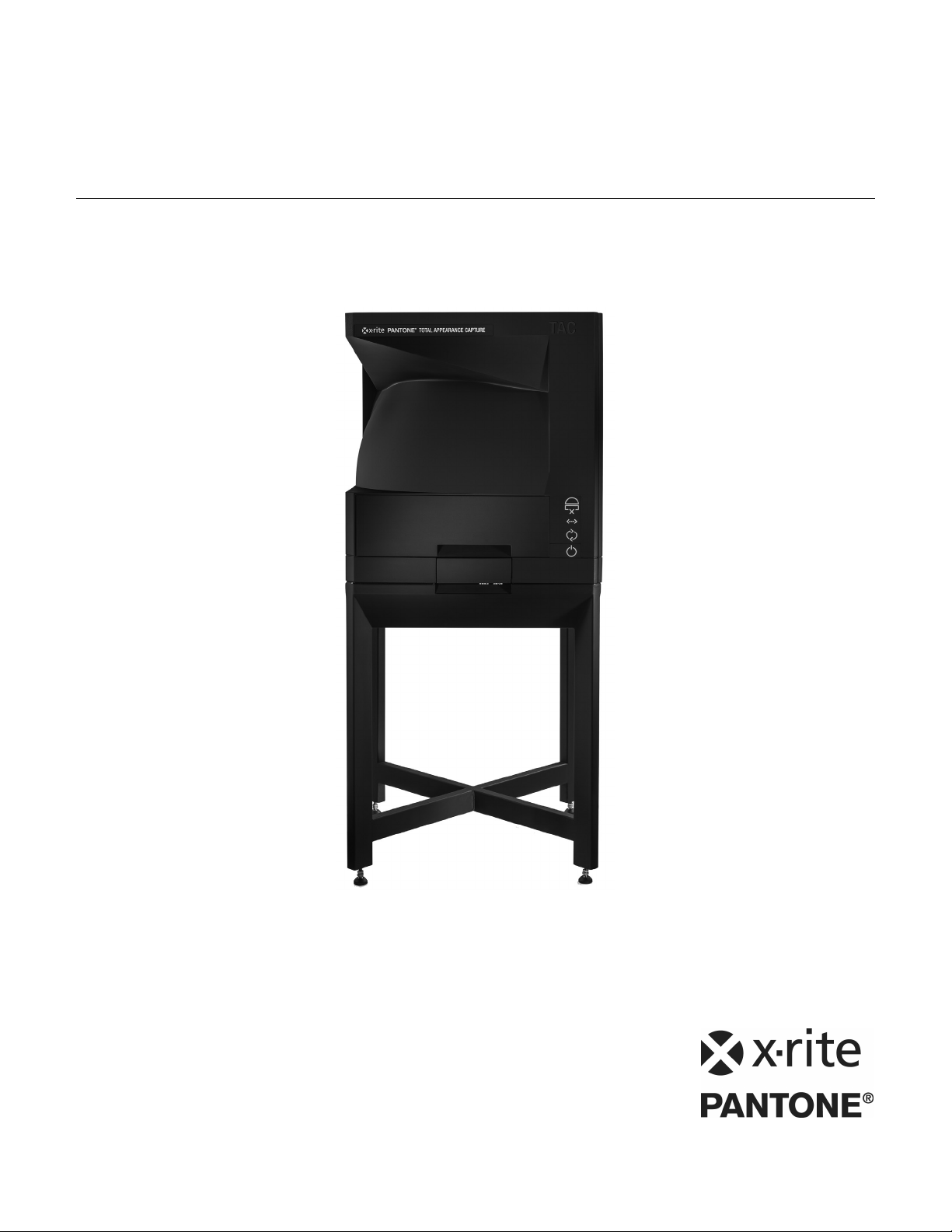
TAC7 Appearance Capture System
Consult this documentation in all cases where the Attention symbol appears.
This symbol is used to inform you of any potential HAZARD or actions that may require
your attention.
CE Declaration
Hereby, X-Rite, Incorporated, declares that this model is in compliance with the essential
requirements and other relevant provisions of Directive(s) 2014/35/EU (LVD), 2014/30/EU (EMC),
and RoHS EU 2015/863, by Category 9 exemption.
NOTE: This is class A products. In a domestic environment this product may cause radio interference
in which case the user will need to consider adequate preventative methods.
Federal Communications Commission Notice
NOTE: This equipment has been tested and found to comply with the limits for a Class A digital
device, pursuant to Part 15 of the FCC Rules. These limits are designed to provide reasonable
protection against harmful interference when the equipment is operated in a commercial
environment. This equipment generates, uses, and can radiate radio frequency energy and, if not
installed and used in accordance with the instruction manual, may cause harmful interference to
radio communications. Operation of this equipment in a residential area is likely to cause harmful
interference in which case the user will be required to correct the interference at his own expense.
Industry Canada Compliance Statement
CAN ICES-3 (A) / NMB-3 (A)
Equipment Information
Use of this equipment in a manner other than that specified by X-Rite, Incorporated may
compromise design integrity and become unsafe.
WARNING: This instrument is not for use in explosive environments.
For indoor use only.
With the exception of the inlet fuse, there are no user serviceable parts in this product.
All warranty and non warranty repairs should be referred to X-Rite, Incorporated.
Instructions for disposal: Please dispose of Waste Electrical and Electronic Equipment (WEEE) at
designated collection points for the recycling of such equipment.
1
Page 4

TAC7 Appearance Capture System
Proprietary Notice
The information contained in this manual is copyrighted information proprietary to X-Rite,
Incorporated.
Publication of this information does not imply any rights to reproduce or use it for purposes other
than installing, operating, or maintaining this instrument described herein. No part of this manual
may be reproduced, transcribed or translated into any language or computer language in any
form or by any means: electronic, magnetic, mechanical, optical, manual, or otherwise; without
the prior written permission of an authorized officer of X-Rite, Incorporated.
Patents: www.xrite.com/ip
“© 2019, X-Rite, Incorporated. All rights reserved”
X-Rite® is a registered trademark of X-Rite, Incorporated. All other logos, brand names, and product names mentioned are the properties
of their respective holders.
Warranty Information
X-Rite warrants this Product against defects in material and workmanship for a period of twelve
(12)months from the date of shipment from X-Rite’s facility, unless mandatory law provides for
longer periods. During such time, X-Rite will either replace or repair at its discretion defective
parts free of charge.
te’s warranties herein do not cover failure of warranted goods resulting from: (i) damage
X-Ri
after shipment, accident, abuse, misuse, neglect, alteration or any other use not in accordance
with X-Rite’s recommendations, accompanying documentation, published specifications, and
standard industry practice; (ii) using the device in an operating environment outside the
recommended specifications or failure to follow the maintenance procedures in X-Rite’
ccompanying documentation or published specifications; (iii) repair or service by anyone other
a
s
than X-Rite or its authorized representatives; (iv) the failure of the warranted goods caused by
use of any parts or consumables not manufactured, distributed, or approved by X-Rite; (v) any
attachments or modifications to the warranted goods that are not manufactured, distributed or
approved by X-Rite. Consumable parts and Product cleaning are also not covered by the
warranty.
ite’s sole and exclusive obligation for breach of the above warranties shall be the repair or
X-R
replacement of any part, without charge, which within the warranty period is proven to X-Rite’s
reasonable satisfaction to have been defective. Repairs or replacement by X-Rite shall not revive
an otherwise expired warranty, nor shall the same extend the duration of a warranty.
C
ustomer shall be responsible for packaging and shipping the defective product to the service
center designated by X-Rite. X-Rite shall pay for the return of the product to Customer if the
shipment is to a location within the region in which the X-Rite service center is located. Customer
shall be responsible for paying all shipping charges, duties, taxes, and any other charges for
products returned to any other locations. Proof of purchase in the form of a bill of sale or
receipted invoice which is evidence that the unit is within the Warranty period must be presented
to obtain warranty service. Do not try to dismantle the Product. Unauthorized dismantling of the
equipment will void all warranty claims. Contact the X-Rite Support or the nearest X-Rite Service
Center, if you believe that the unit does not work anymore or does not work correctly.
2
Page 5

TAC7 Appearance Capture System
THESE WARRANTIES ARE GIVEN SOLELY TO BUYER AND ARE IN LIEU OF ALL OTHER
WARRANTIES, EXPRESSED OR IMPLIED, INCLUDING BUT NOT LIMITED TO THE IMPLIED
WARRANTIES OF MERCHANTABILITY, FITNESS FOR A PARTICULAR PURPOSE OR APPLICATION,
AND NON-INFRINGEMENT. NO EMPLOYEE OR AGENT OF X-RITE, OTHER THAN AN OFFICER OF XRITE, IS AUTHORIZED TO MAKE ANY WARRANTY IN ADDITION TO THE FOREGOING.
IN NO EVENT WILL X-RITE BE LIABLE FOR ANY OF BUYER’S MANUFACTURING COSTS,
OVERHEAD, LOST PROFITS, GOODWILL, OTHER EXPENSES OR ANY INDIRECT, SPECIAL,
INCIDENTAL OR CONSEQUENTIAL DAMAGES BASED UPON BREACH OF ANY WARRANTY, BREACH
OF CONTRACT, NEGLIGENCE, STRICT TORT, OR ANY OTHER LEGAL THEORY. IN ANY EVENT OF
LIABILITY, X-RITE’S MAXIMUM LIABILITY HEREUNDER WILL NOT EXCEED THE PRICE OF THE
GOODS OR SERVICES FURNISHED BY X-RITE GIVING RISE TO THE CLAIM.
3
Page 6

TAC7 Appearance Capture System
Table of Contents
Overview and Installation 5
Packaging Information 5
Instrument Installation Guidelines 6
System Requirements 6
Software Installation 6
Starting PANTORA 6
Operation 7
Powering the Instrument 7
Front Panel 7
Sample Specifications 8
Sample Preparation Process 8
Condition 8
Size 9
Thickness 9
Depth of Field 9
Material Variety Limitations 9
Taking a Measurement 10
Calibration 13
Calibration Procedure 13
Appendices 16
Service Information 16
Troubleshooting 17
Cleaning the Instrument 18
Handling and Care of the White Tile and ColorCheck Target 18
Replacing the Fuse 18
Technical Specifications 19
4
Page 7
TAC7 Appearance Capture System
• TAC7 Instrument
• AC power cord
• White calibration card
• Sample cassette
• Color calibration card
• USB dongle
• Ethernet cable
• Black sample backer
Leveling glides
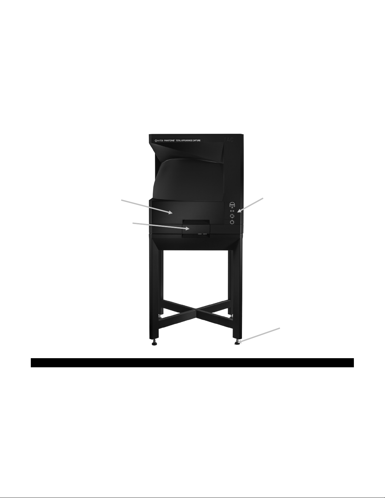
Front status panel
Sample drawer
Sample lift handle
OVERVIEW AND INSTALLATION
The TAC7 device is a completely new instrument based on X-Rite’s Total Appearance Capture
technology. The TAC7 instrument uses 30 light sources and 4 cameras for sampling the material.
Thanks to X-Rite’s highly efficient material description algorithms and high resolution cameras, it
delivers precise material descriptions for many material types (e.g., leather, plastic, textiles,
metals, etc.).
Materials to be measured are placed in the sample drawer that can hold samples up to a size of
210 mm x 297 mm (8.27” x 11.69”) and a maximum weight of 5.45 kg (12 lbs). Refer to the
Sample Specification section later in this manual for additional information.
Packaging Information
Your instrument packaging should contain all the items listed below. If any of these items are
missing or damaged, contact X-Rite or your Authorized Representative.
5
Page 8

TAC7 Appearance Capture System
Instrument Installation Guidelines
X-Rite TAC7 is designed for precision sample measurements. It is important that certain
precautions be taken to ensure the best environment for its use.
• Install on a flat, level surface capable of bearing the load of the instrument.
• When choosing an installation location, make sure not to block the cooling fan.
• Use the leveling glides to account for imperfections in the floor surface.
• Do not place any items on top of the instrument.
Connect the AC cord to an easily accessible outlet.
Discontinue use if AC cord is damaged.
System Requirements
The raw data size of a scan varies between 20 GB and almost 200 GB depending on the
characteristics of your sample. The final AxF files are smaller (5 MB to 150 MB). Copying data
between a measurement PC and a post processing PC can typically become a bottle neck. It is
recommended using either HDD docking stations or hot-swappable tray-less data cages. It is also
recommend using direct SATA hard drive connection and not USB3 as an interface for the disks.
Minimum requirements
Measurement system
• Windows 7 64 bit or Windows 10 64 bit
• 2 network cards (for TAC7 integration)
• 2 hard drives (recommended: 4 hard drives) to transfer data between the
measurement system and the post processing system
Post processing system
• Intel Xeon or Core i7 4th generation or higher recommended (AMD CPUs not tested
by X-Rite)
• 8 virtual cores (e.g. 4 physical and 2x hyper threading (recommended: 10,000 CPU
Marks)
• 16 GB RAM
• 1 TB of free hard drive space
• Nvidia Quadro or GeForce GPU (newer than 2012) with 1 GB RAM (recommended:
5,000 G3D Marks)
Editing and viewing system
• 8 GB of RAM
• Nvidia Quadro or GeForce GPU (newer than 2012) with 1 GB RAM (recommended:
5,000 G3D Marks)
Software Installation
NOTE: Your software may already be installed on your system as part of the system installation.
Follow the steps below if installation of the software is required.
IMPORTANT: You must be logged on as an administrator or a member of the Administrators
group in order to install the software on a Windows 7 or Windows 10 system.
1. Insert the dongle into the USB port and browse to the application.
2. Follow the on screen prompts to install the software.
Starting PANTORA
1. Start PANTORA by double-clicking the desktop icon.
2. Refer to the on-line help for information on using the application.
6
Page 9

TAC7 Appearance Capture System
System ready indicator
Sample cassette indicator
Drawer locked indicator
Connection indicator (connected to TAC7 control software)
Busy indicator
Power button and indicator
OPERATION
Refer to the documentation or online help for the software application that you are using with
your instrument. All applications that use the instrument must be running during measurements.
Powering the Instrument
A power button is located on the front panel of the instrument (see below). This button is used to
power on and power down the instrument into a low power state.
To power on the instrument, press the Power button until the indicator light illuminates. To power
off the instrument, press and hold the Power button until the indicator light goes out.
Discontinue use if AC cord is damaged.
Ensure AC cord ratings meet or exceed the instrument ratings (see Specifications section in
the Appendices).
Front Panel
Use the front panel to turn the instrument on and off. The panel also indicates a variety of
system conditions. Below is description for each indicator and button.
System ready indicator
White: system is ready to measure.
Red: system error occurred.
7
Page 10

TAC7 Appearance Capture System
Sample cassette indicator
White: sample cassette is in place.
Red: system error occurs.
Drawer locked indicator
White: sample drawer is properly locked.
Red: system error occurs.
Connection indicator
White: system is connected to the computer.
Busy indicator
White: system is busy.
Power button and indicator
Powers the instrument on and off. See Powering the Instrument above.
Sample Specifications
In order to correctly measure samples in the TAC7 instrument, the following specifications and
recommendations are provided.
Sample Preparation
To prepare a sample, a portion of the sample is selected for measurement (measured area). If
the original sample is too large, the sample will need to be cut to fit the dimensions. After the
measurement, a region of interest is selected digitally within the measured area for processing.
Condition
As the sample will be captured in great detail, we recommend that:
• Your original sample should be as large as possible. It may be necessary to cut the sample
to the following size recommendations.
• The measured area must be:
o Clean
o Stable (i.e., will not significantly change in response to heat, pressure or movement)
o Free from defects
• The measured area must have a flat surface at the sample presentation plane.
• Samples provided to the scanning surface must also be flat on the back so that custom
fixtures are not necessary.
• Mounted samples can be used if they adhere to the requirements as a whole.
• Labels and other identification should not be visible on the region of interest.
• Materials must have a well-defined surface to generate good results in the fitting process.
8
Page 11

TAC7 Appearance Capture System
Sample size:
Measurement
Measurement area
Size
• Recommended: A single sample should be between
150 x 150 mm and 200 x 200 mm.
• Sample holder is designed to handle up to 297 x 210
mm (A4) samples.
• A clean region of interest must be at least 20 x 20 mm
• The measurement spot of the TAC7 is 130 mm in
diameter. The region of interest must fit into this circle.
297 mm x 210 mm
Sample thickness 30 mm
spot
130 mm
Thickness
• Samples cannot be more than than 30 mm thick.
Depth of Field
Samples can have surface depth variability up to ±3 mm. Materials with overlapping structures
(e.g. tree bark, fur, hair, high floor carpet) are not suitable for measurement (at this time) as
parts of the material will remain invisible for the cameras which can cause artifacts.
Material Variety Limitations
It is not possible to create seamless patterns for materials with large (specifically, larger than an
inscribed rectangle in the 130 mm diameter measurement area) or non-periodic pattern repeats
(e.g. wood, certain fabrics, certain stone types, etc.) except in the case of car paint. The initial
version of the TAC7 is limited to the visible spectrum (VIS) and cannot detect fluorescence.
Optical brightening agents (OBAs) or fluorescent whitening agents (FWAs), which play an
important role in the paper and textile industry, are also not considered in the measurements.
Transparent materials cannot be measured. Also retro-reflection cannot be detected with the
current design of the device.
9
Page 12

TAC7 Appearance Capture System
Cassette
Open Clamp
Open clamp
Sample plate
Sample drawer
Taking a Measurement
Do not measure any liquid, paste, powder, flammable, or combustible substances.
Do not exceed part size and weight recommendations when measuring.
A sample measurement can take anywhere from 20 to 60 minutes to be completed. The
measurement time largely depends on the measurement setup in the application.
Follow these steps to ensure an accurate measurement.
1. Prepare the sample for measurement. See Sample Specification section earlier for additional
information.
2. Start the PANTORA application, select the TAC7 tab, enter a name for the sample and any
additional information as required.
3. Open the sample drawer and carefully remove the cassette from the drawer.
4. Place the cassette on a solid surface. If required open the clamps on the cassette and lower
the sample plate.
10
Page 13

TAC7 Appearance Capture System
Sample
Measurement spot
Sample plate
Closed clamp
Closed clamp
Alignm ent
Alignment pin
Front view of drawer
Side view of drawer
5. Place the sample on the sample plate in the cassette, and align the desired measurement
area below the measurement spot.
6. Lift the sample plate up until it stops against the measurement spot and close the cassette
clamps.
7. Insert cassette with sample into the drawer by placing the cassette over the alignment pins.
pins
11
Page 14

TAC7 Appearance Capture System
Push in handle
Handle closed position
8. Push in sample drawer until it stops.
9. Push in drawer handle to engage cassette to the proper measurement location.
10. Continue with the measurement procedure from the application by clicking Start. Drawer
locked indicator should illuminate when the drawer is properly locked.
11. After measurement is complete, open the drawer and remove the sample from the cassette.
12
Page 15

TAC7 Appearance Capture System
White calibration card on
White calibration card in
CALIBRATION
The software application prompts for an instrument calibration when required. Refer below for
procedure.
A calibration consists of a white tile card measurement followed by a ColorChecker target card
measurement.
The white calibration tile is dramatically affected by smudge marks, dust, and finger prints. Refer
to Appendices for calibration tile handling procedure.
NOTE: Make sure to use the calibration tile supplied with the instrument for calibrating. Do not
substitute a calibration tile from another instrument.
Calibration Procedure
1. Open the sample drawer and lower the sample plate if required. Position the white calibration
card (TAC7-156) on the sample plate so that it completely covers the sample plate.
sample plate
2. Lift the sample plate up until it stops against the measurement spot and close the cassette
clamps.
measurement position
13
Page 16

TAC7 Appearance Capture System
Push in handle
Handle in closed
position
Color calibration card on
3. Push in sample drawer until it stops.
4. Push in drawer handle to engage cassette to the proper measurement location.
5. Start the white calibration process from the application.
6. After the white calibration is complete, open the drawer and lower the sample plate.
7. Remove the white calibration card and return it to the storage sleeve.
8. Position the color calibration card (TAC7-157) on the sample plate so that it completely
covers the sample plate.
sample plate
9. Lift the sample plate up until it stops against the measurement spot and close the cassette
clamps.
14
Page 17

TAC7 Appearance Capture System
Push in handle
Handle in closed
position
Color calibration card in
measurement position
10. Push in sample drawer until it stops.
11. Push drawer handle to engage cassette to proper measurement location.
12. Start the color calibration process from the application. Drawer locked indicator should
illuminate when the drawer is properly locked.
13. After the color calibration is complete, open the drawer and lower the sample plate.
14. Remove the color calibration card and return it to the storage sleeve.
15
Page 18

TAC7 Appearance Capture System
APPENDICES
Service Information
X-Rite provides repair service to their customers. Because of the complexity of the circuitry, all
warranty and non warranty repairs should be referred to an authorized service center. For non
warranty repairs, the customer shall pay shipping and repair cost to the authorized service
center, and the instrument shall be submitted in the original carton, as a complete unaltered unit,
along with all the supplied accessories.
X-Rite also offers on-site system support. Please contact your X-Rite representative for additional
information.
X-Rite, Incorporated has offices around the world. You can contact us using one of the following
methods:
• To identify the X-Rite service center nearest you, please visit our web site at:
www.xrite.com and click the Contact Us link.
• For online help, visit our web site (www.xrite.com) and click the Support link. Here you
can search for software or firmware updates, white papers, or frequently asked questions
which can quickly resolve many common user problems.
• Send an e-mail to Technical Support detailing your problem and listing your contact
information. For the Americas email CASupport@xrite.com, for Europe email
EMEAtechsupport@xrite.com, for Asia email TechSupportAsiaDist@xrite.com.
• For sales questions or to order cables and accessories, visit our web site (www.xrite.com)
or contact your nearest X-Rite dealer or service center.
• Problems and questions can also be faxed or emailed to your local X-Rite office listed on
our website.
16
Page 19

TAC7 Appearance Capture System
Problem
Cause/Solution
Instrument not
AC not connected.
Calibration procedure
Calibration tile is dirty or damaged.
Instrument and
Interface cable not connected.
Instrument
Incorrect Ethernet cable is being used.
Troubleshooting
Prior to contacting the support department for instrument problems, try the applicable solution(s)
described below. If the condition persists, contact us using one of the methods listed in the Service
Information section.
responding (no
indicator lights).
fails.
software not
communicating.
measurements take
an extremely long
time.
Plug in AC line cord.
Fuse is blown.
Replace fuse (see Replacing the Fuse).
Clean the white tile per procedure in Appendix, or replace if damaged. If
damaged, arrange for replacement by contacting X-Rite Support.
Connect the interface cable between the computer and the instrument.
Close and restart the software application. If this does not work, reboot
the computer.
Turn the instrument off then turn the instrument on and see if the
condition is corrected.
Make sure the original Ethernet cable (Cat 6) supplied with the instrument
is used.
17
Page 20

TAC7 Appearance Capture System
Flat-blade
Carrier clip
Fuse
Cleaning the Instrument
In order to maintain accuracy the TAC7 should be operated in an environment free of dust and
other sources of contamination.
If necessary remove dust with a clean, lint free cloth or clean dry air.
IMPORTANT:
Remove AC power from the instrument before performing any cleaning
procedures.
CAUTION: DO NOT use any solvents to clean the instrument.
CAUTION: Use proper personal protective equipment (e.g., safety glasses)
when using compressed air.
If compressed can air is used for any of the cleaning procedures that recommend
air, do not invert or tilt the can during use. This could cause damage.
CAUTION: When using chemicals, always follow the manufacturer’s personal
protection equipment recommendations in the chemical SDS.
Handling and Care of the White Tile and ColorChecker Target
NOTE: Make sure that the white calibration card and color calibration card are always stored in
their protective sleeves when not in use.
If the White Tile or ColorChecker target becomes dirty, brush them as gently as possible with a
dry cloth or blow with a can of compressed air. The tile or color chips can be marred in the
cleaning process, so cleaning liquids should never be used.
Replacing the Fuse
In the event the instrument does not turn ON when power is applied, verify that power is
available at the socket. If power is available, check or replace the instrument fuse as follows.
Replacement fuse (5 mm x 20 mm 3.15A, 250V time-delay fuse type)
1. Turn the power off on the front of the instrument and unplug the detachable line cord.
2. Insert a flat-blade screwdriver into the edge of the fuse carrier and pry out.
3. Remove the blown fuse from the carrier clip and discard.
screwdriver
4. Place the new fuse in the clip and reinsert fuse carrier into the fuse cavity. Make sure the
carrier is firmly seated.
5. Reinstall the detachable line cord.
18
Page 21

TAC7 Appearance Capture System
Technical Specifications
Dimensions: Approx. 74 cm x 74 cm x 172 cm
Weight: 139 kg (306 lbs)
Sample Size & weight: 210 mm x 297 mm (flat surfaces), 5.45 kg max.
Measurement Spot
Dimension:
Pick-up:
Resolution (all cameras): Approx. 350 dpi
Capture Time: SVBRDF acquisition: 20-60 min
Illumination: 20+ white LEDs
Supported representations: SVBRDF +CPA2
Electrical Requirements
Overvoltage Category Category II
EMC Compliance
Operating Temperature
Storage Temperature
130 mm diameter
4 black and white cameras at 0º, 22.5 º, 45º and
67.5º
3 spectral filter wheels
Linear Light Scanner
100-240 VAC/50-60 Hz
AC line input is 250W max
Class 1, protective earth
IEC (EN) 61326-1
FCC Part 15 B
10º C to 40º C
-20º C to 55º C
Altitude, operating 2000 m
Pollution Degree 2
Operating Humidity
Storage Humidity
Design and specifications subject to change without notice.
20% to 80% relative, non-condensing
05% to 90% relative, non-condensing
19
Page 22

Page 23

Page 24

Corporate Headquarters
X-Rite, Incorporated
4300 44th Street SE
Grand Rapids, Michigan 49512
Phone 1 800 248 9748 or 1 616 803 2100
Fax 1 800 292 4437 or 1 616 803 2705
European Headquarters
X-Rite Europe GmbH
Althardstrasse 70
8105 Regensdorf
Switzerland
Phone (+41) 44 842 24 00
Fax (+41) 44 842 22 22
Asia Pacific Headquarters
X-Rite Asia Pacific Limited
Suite 2801, 28th Floor, AXA Tower
Landmark East, 100 How Ming Street
Kwun Tong, Kowloon, Hong Kong
Phone (852) 2568 6283
Fax (852) 2885 8610
Please visit www.xrite.com for a local office near you.
P/N TAC7EN-500 Rev. A
 Loading...