

Page 1

X-Rite® MA48
Multi-Angle Spectrophotometer
Operator’s Manual
Page 2

Page 3

Equipment Information
FCC
This equipment has been tested and found to comply with the limits for a Class
A digital device, pursuant to Part 15 of the FCC Rules. These limits are
designed to provide reasonable protection against harmful interference when
the equipment is operated in a commercial environment. This equipment
generates, uses, and can radiate radio frequency energy and, if not installed
and used in accordance with the instruction manual, may cause harmful
interference to radio communications. Operation of this equipment in a
residential area is likely to cause harmful interference in which case the user will
be required to correct the interference at his own expense.
NOTE: Shielded interface cables must be used in order to maintain compliance
with the desired FCC and European emission requirements.
Canada
This digital apparatus does not exceed the Class A limits for radio noise
emissions from digital apparatus set out in the Radio Interference Regulations of
the Canadian Department of Communications.
Le présent appareil numérique n'émet pas de bruits radioélectriques dépassent
les limites applicables aux appareils numériques de la class A prescrites dans le
Règlement sur le brouillage radioélectrique édicte par le ministère des
Communications du Canada.
AVERTISSEMENT : Des câbles d'interface blindés doivent être utilisés afin de
se conformer aux règlements européens et FCC (USA)sur l'émission.
CE Declaration
Manufacturer's Name: X-Rite, Incorporated
Manufacturer's Address: 4300 44
Grand Rapids, Michigan 49512
U.S.A.
Model Name: Multi-Angle Spectrophotometer
Model No.: MA48
Directive(s) Conformance: EMC 89/336/EEC LVD 73/23/EEC
Warning:
This is a class A product. In a domestic environment this product may cause radio
interference in which case the user may be required to take adequate measures.
WEEE
As of August 13, 2005, X-Rite products meet the European Union –
Waste Electrical and Electronic Equipment (WEEE) directive.
Please refer to www.xrite.com
compliance with the WEEE directive.
th
Street, S.E.
for more information on X-Rite’s
i
Page 4

Environmental Specifications
Operating Temp: 10° - 40°C
Relative Humidity: 0 - 85% non condensing
Usage: Indoor Only
Altitude: 2000m
Pollution Degree: 2
Overvoltage: Category II
WARNING: This instrument is not for use in explosive environment.
Input Power Requirements
12/15Vdc, 700/560mA
Use Only: X-Rite No. SE30-81 (North America)
X-Rite No. SE30-77 (International)
ii
Page 5

Table of Contents
Proprietary Notice........................................................................................................................... iv
Limited Warranty............................................................................................................................ iv
1. Setup and Overview...................................................................................................... 1-1
Unpacking and Inspection............................................................................................................. 1-1
Packaging Content................................................................................................................. 1-1
Instrument Description.................................................................................................................. 1-1
Docking Station Description.........................................................................................................1-2
Setting Up the System...................................................................................................................1-2
Main Screen Description............................................................................................................... 1-4
Button Operation........................................................................................................................... 1-4
Adjusting Display Contrast...........................................................................................................1-5
Optional Barcode Reader (BCR) .................................................................................................. 1-5
Using the Barcode Reader ..................................................................................................... 1-5
Measurement Techniques..............................................................................................................1-6
Measurement Averaging...............................................................................................................1-6
Measurement Sequence..........................................................................................................1-6
2. Instrument Calibration.................................................................................................. 2-1
General Information......................................................................................................................2-1
White Calibration Reference.........................................................................................................2-1
Zero Reflectance........................................................................................................................... 2-2
Calibration Procedure ................................................................................................................... 2-3
3. Setting Instrument Configuration................................................................................ 3-1
Display Options.............................................................................................................................3-1
Measure Options........................................................................................................................... 3-2
Set Clock.......................................................................................................................................3-3
Communications ...........................................................................................................................3-4
Languages ..................................................................................................................................... 3-5
Battery Refresh Operation.............................................................................................................3-5
4. Instrument Operation....................................................................................................4-1
Reference Mode............................................................................................................................ 4-1
Selecting a Reference Number and Measuring......................................................................4-1
Selecting the Tolerance Type and Editing Values................................................................. 4-2
Store Mode....................................................................................................................................4-3
Selecting a Group/Reference and Measurement....................................................................4-4
Changing Color Space and Illuminant/Observer ................................................................... 4-4
Switching Between Pass/Fail Indication and Difference Data...............................................4-5
Edit Menu (Print, View and Delete) ......................................................................................4-5
Tagging Samples (using the optional BCR)...........................................................................4-7
Normal Mode................................................................................................................................4-8
5. Service and General Maintenance............................................................................... 5-1
Repair Information........................................................................................................................5-1
Cleaning the Instrument and Docking Station ..............................................................................5-1
Cleaning the Optics.......................................................................................................................5-1
Battery Replacement Information.................................................................................................5-2
Cleaning the Calibration Reference ..............................................................................................5-2
Cleaning the Zero Reflectance Trap..............................................................................................5-2
Troubleshooting Tips....................................................................................................................5-3
Error Messages.............................................................................................................................. 5-4
Reading Error Messages........................................................................................................ 5-4
Calibration Error Messages....................................................................................................5-4
Miscellaneous Error Messages...............................................................................................5-4
Specifications................................................................................................................................5-5
iii
Page 6

Proprietary Notice
The information contained in this manual is derived from patent and proprietary data of
X-Rite, Incorporated. This manual has been prepared solely for the purpose of assisting
in the use and general maintenance of this instrument.
The contents of this manual are the property of X-Rite, Incorporated and are copyrighted.
Any reproduction in whole or part is strictly prohibited. Publication of this information
does not imply any rights to reproduce or use this manual for any purpose other than
installing, operating, or maintaining this instrument. No part of this manual may be
reproduced, transcribed, transmitted, stored in a retrieval system, or translated into any
language or computer language, in any form or by any means, electronic, magnetic,
mechanical, optical, manual, or otherwise, without the prior written permission of an
officer of X-Rite, Incorporated.
This instrument may be covered by one or more patents. Refer to the instrument for
actual patent numbers.
Copyright © 2007 by X-Rite Incorporated
“ALL RIGHTS RESERVED”
Limited Warranty
X-Rite, Incorporated (“X-Rite”) warrants each instrument manufactured to be free of
defects in material and workmanship (excluding battery pack) for a period of 12 months.
This warranty shall be fulfilled by the repair or replacement, at the option of X-Rite, of
any part or parts, free of charge including labor, F.O.B. its factory or authorized service
center.
This warranty shall be voided by any repair, alteration, or modification, by persons other
than employees of X-Rite, or those expressly authorized by X-Rite to perform repairs,
and by any abuse, misuse, or neglect of the product, or by use not in accordance with XRite’s published instructions.
X-Rite reserves the right to make changes in design and /or improvements to its products
without any obligation to include these changes in any products previously
manufactured. Correction of defects by repair or replacement shall constitute fulfillment
of all warranty obligations on the part of X-Rite.
THIS WARRANTY IS EXPLICITLY IN LIEU OF ANY OTHER EXPRESSED OR
IMPLIED WARRANTIES, INCLUDING ANY IMPLIED WARRANTY OF
MERCHANTABILITY OR FITNESS FOR ANY PARTICULAR PURPOSE. THIS
WARRANTY OBLIGATION IS LIMITED TO REPAIR OR REPLACEMENT OF
THE UNIT RETURNED TO X-RITE OR AN AUTHORIZED SERVICE CENTER
FOR THAT PURPOSE.
This agreement shall be interpreted in accordance with the laws of the State of Michigan
and jurisdiction and venue shall lie with the courts of Michigan as selected by X-Rite,
Incorporated.
iv
X-Rite® is a registered trademark of X-Rite, Incorporated
All other logos, product names, and trademarks mentioned are the property of their respective holders.
Page 7
1. Setup and Overview
Unpacking and Inspection
After removing the instrument from the shipping carton, inspect for possible damage. If
any damage occurred during shipping, immediately contact the transportation company.
Do not proceed with installation until the carrier’s agent has inspected the damage.
Your instrument was packaged in a specially designed carton to assure against damage. If
reshipment is necessary, the instrument should be packaged in the original carton. If the
original carton is not available, contact X-Rite (1-888-826-3042 or 1-616have a replacement shipped to you.
Packaging Content
Your packaging should contain the all the items listed below. If any of these items are
missing, contact X-Rite or an Authorized Representative.
• MA48 Instrument
• Docking Station
• Interface Cable
• AC Adapter
• White Calibration Reference
• Documentation and Registration Material
803-2100) to
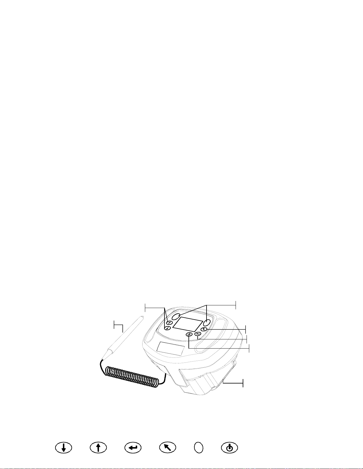
Instrument Description
The MA48 multi-angle spectrophotometer is designed for measuring color on metallic
and pearlescent paint finishes. The instrument incorporates a single light source and five
fixed—aspecular—viewing angles (15°, 25°, 45°, 75°, and 110°).
To ensure measurement accuracy, the MA48 also includes a two read-switch triggering
mechanism. This allows a measurement to be taken only after the spectrophotometer has
been properly positioned.
Tab Buttons
Barcode Reader
Read Buttons
Back Button
Enter Button
On/Off Button
Sensor Nose
Tab Down Tab Up Enter Back Read On/Off
1-1
Page 8

SECTION ONE
Docking Station Description
The docking station provides several important functions:
White Reflectance Standard
Setting Up the System
• storage of the instrument for nonuse times
• data transfer to the local computer (RS-232 or USB interface connection)
• charging of the instrument’s internal battery (refer to section 3: Battery Refresh
Operation)
• an open port for zero reflectance readings and storage for the white cal reference
Zero Reflectance Port
Computer and Charger
Connections
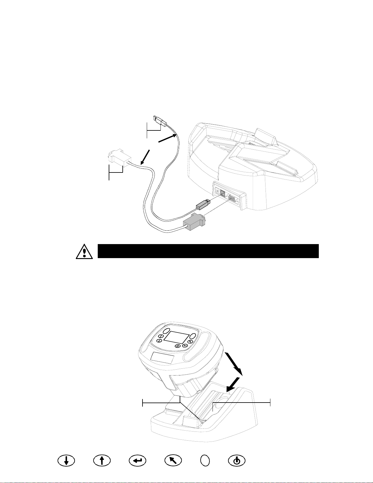
Use only X-Rite power supply P/N SE30-81 (manufacturer’s P/N J06ADT-53)
or P/N SE30-77 (manufacturer’s P/N PSA30U-120).
1. Locate the docking station next to the computer.
2. Plug the small connector end of the power supply into the back of the docking station.
3. Domestic Power Supply - Plug the adapter into an AC wall receptacle.
Export Power Supply - Plug the detachable line cord into the power supply and then
plug the line cord into an AC wall receptacle.
OR
Power Supply
(export)
Detachable Line Cord
Power Supply
(domestic)
1-2
4. DB9 Serial Interface (Standard)
Connect the DB9 plug onto the 9-pin I/O port on the back of the instrument. Connect
the other end into an available computer COM port.
Tab Down Tab Up Enter Back Read On/Off
Page 9
DB9 Serial Cable
(standard)
SETUP AND OVERVIEW
USB Cable Interface (optional)
Plug the square end of the USB cable into the back of the docking station. Connect
the other end of the USB cable to an available USB port on back of the computer.
After connecting the USB cable to your computer, a “Found New Hardware”
message appears on the screen. You must install the USB driver for the instrument to
communicate with your computer. Insert the Manuals and Utilities CD that came
with your instrument into the CD drive and follow the instructions on the screen.
The USB driver is located in the “Driver” folder on the CD.
USB Cable
(optional)
OR
The instrument automatically goes into “charge mode” when it is placed on the
docking station.
5. Place the instrument onto the powered docking station by positioning the sensor nose
in the recessed area and sliding downward. Make sure the connector on the
instrument is properly seated to the connector on the docking station. A “two-beep”
conformation signal is heard and a “lighting bolt” icon appears in the lower right
portion of the main screen when properly seated. The instrument must initially remain
on the docking station for a minimum of four hours to allow the internal batteries to
fully charge.
Connectors
Recessed Area
Tab Down Tab Up Enter Back Read On/Off
1-3
Page 10

SECTION ONE
A
Main Screen Description
When the instrument is powered-up, the main (top level) screen appears. The main menu
consists of two areas, Operating Modes and Instrument Data. The left side of the screen
lists all available modes. The right side of the screen lists the instrument name, firmware
version and serial number.
Instrument Name
Firmware Version and
Serial Number
“lighting bolt” icon indicates the
instrument is docked and charging
Operating Modes
–MAIN MENU–
Store
Normal
References
Calibrate
Config.
MA48
——————
XXXX
******
Button Operation
Perform reading and menu/option navigation with the six buttons arranged around the
display screen. Each button has a unique symbol for performing a specific operation.
On/Off
Controls the instrument’s power status when it is not in the docking station. As an added
feature to conserve battery life, the instrument automatically powers down after five
minutes of nonuse. The On/Off button must be used to turn on the instrument after an
auto power down.
Tab Down
Advances the highlighted bar (reverse image) to the next available “tab stop.” A tab stop
indicates an item that can be acted on further, such as a measurement or an edit option.
Tab stops generally follow a left-to-right or top-to-bottom sequence. When the last tab
stop is reached, the next button press returns to the first tab stop in that menu's list. The
button is also used to increment numeric values in the Reference mode.
1-4
Tab Up
Performs the same function as the Tab Down button except in reverse order. Tab stops
follow a right-to-left or bottom-to-top sequence.
Enter
Used to activate/select the control chosen (highlighted) with the tab buttons. If the
control can be set on or off, pressing the button toggles the option between on and off.
Back
Backs up the instrument screen one menu level. For example, if an option or value is
being modified at the time the button is pressed, the edits are aborted and the previous
screen or menu appears. The only exception to this is when the Enter button is used to
toggle an option. In this case, the Back button exits the menu without aborting the
setting.
Read
Initiates a reading when either Read button is pressed and both read switches are
activated.
Tab Down Tab Up Enter Back Read On/Off
Page 11

SETUP AND OVERVIEW
Adjusting Display Contrast
The contrast of the display can be adjusted for optimal viewing. Make sure the
instrument screen is at the main menu before changing.
To adjust, hold down Back and press Tab Up to increase contrast or Tab Down to
decrease contrast.
Increase Contrast
Decrease Contrast
–MAIN MENU–
Store
Normal
References
Calibrate
Config.
MA48
——————
XXXX
******
Optional Barcode Reader (BCR)
The barcode reader should only be used for its intended application (barcodes).
Never look directly into the beam of light or direct the beam of light luminating at
the tip of the reader in the direction of someone’s eyes.
The instrument utilizes a barcode reader as a means of attaching tags to samples. Sample
data that is uploaded from the instrument to the computer will include scanned tags.
Refer to the end of Section Four for information on scanning tags in Store Mode.
Using the Barcode Reader
The barcode reader is stored in a recessed area on the front edge of the instrument when
not in use. Simply press it into the holder area to secure.
Recessed Area
Hold Down
Follow these guidelines for successful bar code scanning.
1. Hold the BCR in your hand as you would a pencil. The BCR work s
best when slightly tilted.
2. Place the tip of the BCR on the white space to the left or right of
the barcode. Drag the BCR smoothly and lightly across the bar
code. Do not lift the tip of the BCR from the surface of the bar
code.
3. If the scan was successful, an audible beep is heard and
the instrument displays the title of the barcode. If an
audible beep is not heard, try scanning the
barcode again.
Tab Down Tab Up Enter Back Read On/Off
1-5
Page 12

SECTION ONE
Measurement Techniques
In order to obtain accurate and repeatable measurements, the bottom of the sensor nose
must be flat with the surface to be measured. Any movement of the sensor nose can cause
the measurement angles to vary, greatly affecting measurements on metallic paint finishes.
Measurements performed on a surface with a curve can cause the instrument to display a
“Light Leakage” error. This is caused by stray light entering the measurement aperture.
A measurement takes place when both switches are activated on the bottom of the sensor
nose. It may also be necessary to press one of the Read buttons to complete the
measurement if the option is set in the Configuration mode. To achieve the b est
measurement repeatability, apply even pressure to both sides of the instrument during a
measurement. The beginning and end of the measurement is signaled by audible beeps.
Hold the instrument firmly until “MEASUREMENT COMPLETE” message is
displayed.
Measurement Averaging
Measurement averaging is used to obtain an average value from various locations across
a sample. The averaging option is activated in the Configuration mode and can be set
from one to 99 measurements. All modes with the exception of Calibration use averaging
when activated.
Measurement Sequence
1. Select mode of operation (Store, Normal or Reference).
2. Position instrument on first area of sample and take the measurement. The current
measurement out of remaining measurements is displayed (e.g., 1 of 3).
NOTE: Averaging can be aborted at any time by pressing the Back button.
3. Position the instrument on the next area on the sample and take the measurement.
4. Continue with all required measurements.
5. After the last average measurement is taken, Averaging Complete appears on the
screen and then the averaged data.
1-6
Tab Down Tab Up Enter Back Read On/Off
Page 13

2. Instrument Calibration
General Information
Regular calibration of the instrument is important in maintaining accurate measurements.
The instrument should be calibrated to the white standard and docking station (zero
reference port) the first thing each day, and every twelve hours of operation
thereafter. A Cal Required message appears in the display when the calibration
procedure has not been performed for 12 hours.
Whenever this message appears in the display, the calibration procedure must be
performed. No measurements can be taken until calibration is completed.
Calibration Notes
• Dirt or dust in the optics area will cause an inaccurate calibration reading. Refer
to Section Four for optics cleaning procedure.
• The white calibration reference is dramatically affected by smudge marks, dust,
and fingerprints. Refer to Section Five for white calibration cleaning procedure.
• Do not move instrument while taking calibration measurements. If motion is
detected, an error message displays and the calibration is aborted.
White Calibration Reference
The white calibration reference is stored on the left side of the docking station and is
designed to keep the reflection tile free of dust and debr is.
White Calibration Reference
Tab Down Tab Up Enter Back Read On/Off
2-1
Page 14

SECTION TWO
The white calibration reference tile is concealed in a case that has a hinged cover.
Position the sensor nose of the instrument in the case and take the measurements. Make
sure the calibration tile is positioned directly under the measurement aperture.
Hinged Cover
Calibration Tile
Zero Reflectance
The docking station is used to perform the zero reflectance measurement portion of the
calibration procedure. Place the instrument in its normal position on the station and the
take the measurements over the cutout beneath the sensor nose.
2-2
Zero Reflectance Port
Tab Down Tab Up Enter Back Read On/Off
Page 15

INSTRUMENT CALIBRATION
Calibration Procedure
The calibration procedure consists of two white reference measurements followed by
four zero reflectance measurements.
1. Use Tab Down or Tab Up to highlight Calibrate. Press Enter to access the calibration
function.
–MAIN MENU–
Store
Normal
Reference
Calibrate
Config.
The instrument displays the calibration status and reference serial number. The serial
number displayed must match the number listed on the calibration reference. If the
calibration status is OK, no calibration is required at this time. If Cal Required is the
current status, you must perform the calibration procedure before continuing with any
additional measurements.
Calibration
Measure White Ref
Press Firmly
Status: Cal Required
S/N: XXXXX
MA48
——————
XXXX
******
2. Remove the white calibration reference from the docking station and position the
instrument on the reference as previously discussed. Hold the instrument down and
momentarily press one of the Read buttons. Hold steady until the instrument indicates
that both the white calibration readings are complete.
3. After successful white calibration readings, position the instrument in its normal position
on the docking station. The display indicates that the Black Ref measurements are now
required. Hold the instrument steady against the docking station and momentarily press
one of the Read buttons to take the measurements. You must keep the instrument steady
through all four measurements.
After the measurements are completed, the display automatically returns back to the main
menu.
Tab Down Tab Up Enter Back Read On/Off
2-3
Page 16

SECTION TWO
2-4
Tab Down Tab Up Enter Back Read On/Off
Page 17

3. Setting Instrument Configuration
The Configuration mode consists of a several settings that can be edited to customize
your instrument for your particular application.
1. Use Tab Down or Tab Up to highlight Config.
–MAIN MENU–
Store
Normal
References
Calibrate
Config.
2. Press Enter to access the Configuration mode.
CONFIGURATION
Display Options
Measure Options
Set Clock
Communications
Language
Display Options
MA48
——————
XXXX
******
The Display Options allows you to configure the following settings:
Active ∆E – Allows you to choose the Delta E method that is available in Store and
Normal modes. Available settings are: ∆E
*a*b*
, ∆Ecmc, ∆Ec6175, ∆Ep6175 and ∆Ee6175.
Active Illum/Obs – Allows you to select the illuminant/observer combinations available
in Store and Normal mode. An arrow (>) indicates the illum/obs combination is active.
Active Angles – Allows you to select which three angles are displayed on the screen in
Store mode and Reference mode. Available setting are: “15°/45°/75°”, “25°/45°/75°”,
“25°/45°/110°”, and “15°/45°/110°.”*
15°/45°/110° viewing geometry by license from E.I. DuPont de Nemours and Co., Inc. U.S. Patent No. 4,479,718.
Editing Display Options
1. Press Tab Up or Tab Down to move the highlight to Display Options.
CONFIGURATION
Display Options
Measure Options
Set Clock
Communications
Language
2. Press Enter to access the Display Options menu.
Display Options
Active ∆E
Active Illum/Obs
Active Angles
Active ∆E
1. Press Tab Up or Tab Down to move the highlight to Active ∆E and press Enter to
open the Active ∆E editor.
2. Press Tab Up or Tab Down to move the highlight to desired ∆E and press Enter to
select setting and exit editor.
Tab Down Tab Up Enter Back Read On/Off
3-1
Page 18

SECTION THREE
Active Illuminate/Observer
1. Press Tab Up or Tab Down to move the highlight to Active Illum/Obs and press
Enter to open the Active Illum/Obs editor.
2. Press Tab Up or Tab Down to move the highlight to the desired 10° combination and
press Enter to toggle the combination active or inactive. The arrow (>) indicates
active.
3. To edit 2° combinations, highlight To 2° using Tab Up or Tab Down and press Enter.
4. Press Tab Up or Tab Down to move the highlight to the desired 2° combination and
press Enter to toggle the combination active or inactive. The arrow (>) indicates
active.
5. After edits are complete, press Back to save and exit the illum/obs editor.
Active Angles
1. Press Tab Up or Tab Down to move the highlight to Active Angles and press Enter
to open the Active Angles editor.
2. Press Tab Up or Tab Down to move the highlight to Angle #1 and press Enter to
toggle between 15° and 25°.
3. Press Tab Up or Tab Down to move the highlight to Angle #3 and press Enter to
toggle between 75° and 110°.
4. After edits are complete, press Back to save and exit the editor.
Measure Options
The Measure option allows you to configure the following settings:
Auto Ref – Sets the automatic reference option. When Auto Reference is enabled (on),
the stored reference that most closely matches the measured sample is automatically
selected during a Store or Normal measurement. When Auto Reference is disabled (off),
you must manually select a reference before taking a measurement.
Averaging –Sets the number of readings (0-99) required to obtain an averaged
measurement.
Read Action – Allows you to have the measurement activated by bottom switches (Foot
Switches only), Read button (Read Key only), or in combination of the Read button and
bottom switches (Switch & Key req.).
Editing Measure Options
1. Press Tab Up or Tab Down to move the highlight to Measure Options.
CONFIGURATION
Display Options
Measure Options
Set Clock
Communications
Language
2. Press Enter to access the Measure Options editor.
Measure Options
Auto Ref: On
Averaging : 1
Read Action
3-2
Tab Down Tab Up Enter Back Read On/Off
Page 19

SETTING INSTRUMENT CONFIGURATION
Auto Reference
• Press Tab Up or Tab Down to move the highlight to Auto Ref and press Enter to
toggle between Off and On.
Averaging
1. Press Tab Up or Tab Down to move the highlight to Averaging and press Enter to
active the averaging # editor (up/down arrows appear to the left).
2. Press Tab Down to page backward through the averaging numbers, or press Tab Up
to page forward through the numbers.
3. Press Enter to select the displayed averaging number.
NOTE: Use the Back button to revert back to the original setting.
Read Switches
1. Press Tab Up or Tab Down to move the highlight to Read Action and press Enter
to open the read action editor.
2. Press Tab Up or Tab Down to move the highlight to Foot switches only, Read Key
only, or Switch & Key req. and press Enter to save selection and exit.
Exiting Measure Option
• After you have completed all the measure option editing, press Back to return to the
Configuration menu.
Set Clock
The Set Clock configuration is used to adjust the internal clock of the instrument.
1. Press Tab Up or Tab Down to move the highlight to Set Clock.
CONFIGURATION
Display Options
Measure Options
Set Clock
Communications
Language
2. Press Enter to access the Set Clock editor.
Day : 09
Month : 01
Year : 03
Hour : 10
Minute : 25
3. Press Tab Up or Tab Down to move the highlight to Day, Month, Year, Hour or Minute
and press Enter to activate the editor (up/down arrows appear to the left).
4. Press Tab Down to page backward through the digits, or press Tab Up to page forward
through the digits.
5. Press Enter to select the displayed digit.
NOTE: Use the Back button to revert back to the original setting.
6. Continue with additional date/time edits as required.
Set Clock
Exiting Clock Set Option
• After you have completed all the clock editing, press Back to return to the Configuration
menu.
Tab Down Tab Up Enter Back Read On/Off
3-3
Page 20

SECTION THREE
Communications
The Communication option allows you to configure the following settings:
Baud Rate – Determines the data input/output rate of the instrument. The rate can be set
at 9600 or 19200.
Automatic LF – Varies the delimiter at the end of each line of data. When set to LF On,
a line feed is sent at the end of a line of data. When set to LF Off, no line feed is sent at
the end of the line of data.
Data – Determines the type of data output from the instrument. When set to Color, color
space data (L*a*b*, etc.) is output. When set to Spectral, spectral data in 10nm
increments is output.
Header – Determines if the header information (L*a*b*, etc.) is output with
measurement data. If set to Off, no header information is output. If set to On, header
information is output.
Ref. Printout – Determines if the reference data is output with measurement data. If set
to Off, no reference data is output. If set to On, reference data is output.
Editing Communications Options
1. Press Tab Up or Tab Down to move the highlight to Communications.
CONFIGURATION
Display Options
Measure Options
Set Clock
Communications
Language
2. Press Enter to access the Communications editor.
Communication
Baud Rate : 9600
Automatic LF: On
Data: Color
Header: Off
Ref. Printout: Off
Baud Rate
• Press Tab Up or Tab Down to move the highlight to Baud Rate and press Enter to
toggle between 9600 and 19200.
Auto Line Feed
• Press Tab Up or Tab Down to move the highlight to Automatic LF and press Enter
to toggle between Off and On.
Data
• Press Tab Up or Tab Down to move the highlight to Data and press Enter to toggle
between Color and Spectral.
Header
• Press Tab Up or Tab Down to move the highlight to Header and press Enter to
toggle between Off and On.
Ref. Printout
• Press Tab Up or Tab Down to move the highlight to Ref. Printout and press Enter
to toggle between Off and On.
3-4
Tab Down Tab Up Enter Back Read On/Off
Page 21

SETTING INSTRUMENT CONFIGURATION
Exiting Communication Option
• After you have completed all the communications editing, press Back to return to
the Configuration menu.
Languages
The Language configuration allows you to select the language you want to display on
your instrument.
1. Press Tab Up or Tab Down to move the highlight to Language.
CONFIGURATION
Display Options
Measure Options
Set Clock
Communications
Language
2. Press Enter to access the Language editor.
Language
English Chinese Simp
Deutsch Japanese
Français
Espanol
Italiano
Portugues
3. Press Tab Up or Tab Down to move the highlight to the desired language.
4. Press Enter to save the selected language. The instrument returns to the Configuration
menu with the selected language active.
Battery Refresh Operation
Your instrument is powered by a Ni-metal hydride battery pack. Because the battery will
start to charge every time the instrument is docked in the station, this can, overtime reduce
the capacity of the battery. Refreshing is the process of allowing your instrument’s battery
to drain completely and then charging all cells in the battery to 100%. Refreshing the
battery from time-to-time helps extend the duration of use and life of the battery.
The process for refreshing the battery takes approximately eight hours and should be
performed once a month. As the instrument cannot be used during this operation and
must remain in the docking station the entire time, it is suggested that this procedure be
performed at the end of a workday to minimize disruption.
1. Place the instrument in the docking station.
2. Press Tab Up or Tab Down to move the highlight to the Battery icon and then press Enter.
CONFIGURATION
Display Options
Measure Options
Set Clock
Communications
Language
3. You are asked if you are sure you would like to begin the refresh operation. Press Tab
Up or Tab Down to move the highlight to Yes and press Enter.
The instrument displays “Please Wait, battery maintenance in progress” during the
discharge phase of the operation. This screen automatically disappears when the charging
portion of the operation begins.
NOTE: To abort the refresh operation at anytime, simply power down the
instrument and then power it back up.
Tab Down Tab Up Enter Back Read On/Off
3-5
Page 22

SECTION THREE
3-6
Tab Down Tab Up Enter Back Read On/Off
Page 23

A
A
4. Instrument Operation
Reference Mode
The instrument can store a maximum of 100 references with tolerances which are
accessible in the Store and Normal modes. The reference mode is used to measure
references and edit their tolerances. References can also be downloaded from an X-Rite
software application, such as X-RiteColor Master. If a reference is downloaded, it can be
viewed but not edited.
1. Use Tab Up or Tab Down to highlight References.
–MAIN MENU–
Store
Normal
References
Calibrate
Config.
2. Press Enter to access the reference mode.
MA48
——————
XXXX
******
Current reference number
Reference: 1
Tolerance: ∆L
Edit Tolerances
31.43 24.57 262.34
30.50 24.45 262.14
32.41 26.03 262.19
*a*b*
Tolerance type for selected reference
ccesses tolerance editing menu
ngle data for current reference
Selecting a Reference Number and Measuring
The reference mode has a special control that is used to select a reference number. The
list can be paged through either forward or backward to reduce time.
Reference number will be replaced with the reference name when downloaded from
X-RiteColor Master software.
1. Use Tab Up or Tab Down to highlight Reference: ##.
2. Press Enter to activate the editor. Up/down arrows appear at the left.
Reference: 1
Indicates the editor
control is active
Tolerance: ∆L
Edit Tolerances
31.43 24.57 262.34
30.50 24.45 262.14
32.41 26.03 262.19
3. Press Tab Down to page backward through the reference numbers, or press Tab Up to
page forward through the list. To quickly page through the references, hold down one of
the Tab keys.
4. Press Enter to select the displayed reference number.
NOTE: Use Back to revert back to the original reference.
*a*b*
5. Refer to section 1: Measurement Techniques for information on proper positioning.
Position the instrument over the reference and take the measurement. The selected angles
appear momentarily during the measurement.
NOTE: If the averaging option is activated in the Configuration mode, you must
make additional measurements on the reference. Refer to section 1:
Measurement Averaging for additional information.
Tab Down Tab Up Enter Back Read On/Off
4-1
Page 24

SECTION FOUR
Selecting the Tolerance Type and Editing Values
After selecting a reference number and measuring a reference, you can select a tolerance
type and edit tolerance values. If a tolerance is not going to be used, select the NONE
option. The tolerance type and values cannot be changed if the reference number is
empty or if the reference was downloaded.
The attributes that are available for adjustment depend on the tolerance type selected.
• ∆E*a*b*, ∆Ec6175, ∆Ep6175 and ∆Ee6175 tolerance types allows tolerance
adjustment for each angle.
• ∆FI tolerance type allows high/low tolerance adjustment for the flop index.
• ∆L*a*b* and ∆L*C*h tolerance types allows high/low tolerance adjustment for each
angle.
• ∆Ecmc tolerance type allows a global adjustment for “l” (lightness factor) and “c”
(chromaticity factor). The “cf” (commercial factor) can be adjusted for each angle).
1. Use the Tab Up or Tab Down to highlight Tolerance:.
2. Press Enter to page through the tolerance types: None, ∆L*a*b*, ∆L*C*H*, ∆FI,
∆E*a*b*, ∆Ecmc, ∆Ec6175, ∆Ep6175 and ∆Ee6175.
Reference: 1
Tolerance: ∆L
Edit Tolerances
31.43 24.57 262.34
30.50 24.45 262.14
32.41 26.03 262.19
3. After selecting the tolerance type, use Tab Down to highlight Edit Tolerances.
Reference: 1
Tolerance: ∆L
Edit Tolerances
31.43 24.57 262.34
30.50 24.45 262.14
32.41 26.03 262.19
*a*b*
*a*b*
4. Press Enter to access the tolerance editing screen.
Reference: 1
Tolerance: ∆L
Set 15° High
∆L* ∆a* ∆b
+1.00 +2.00 +1.00
<< >>
*a*b*
*
Selecting an Angle and High/Low Tolerance for Editing
The angles and high/low tolerances available for editing depends on the tolerance type
selected. All angles and high/low tolerances for each tolerance type are selected using the
same method.
1. Press Tab Up or Tab Down to move the highlight to the left double arrow (<<) or
the right double arrow (>>).
2. Press Enter to page through the available angle and/or high/low tolerance screens.
Reference: 1
Tolerance: ∆L
Set 15° High
∆L* ∆a* ∆b
+1.00 +2.00 +1.00
<< >>
Pages forward
through the angles
*a*b*
*
Reference: 1
Tolerance: ∆L*a*b*
Set 15° Low
∆L* ∆a* ∆b
-1.00 -2.00 -1.00
<< >>
Pages backward
through the angles
*
3. After selecting an angle tolerance, advance to Editing an Attribute Value.
4-2
Tab Down Tab Up Enter Back Read On/Off
Page 25

Editing an Attribute Value
The attributes available for editing depend on the tolerance type selected. Values for all
types are edited in the same manner.
1. Press Tab Up or Tab Down to move the highlight to a tolerance attribute.
2. Press Enter to activate the editor. Up/down arrows appear at the left.
Indicates the editor
control is active
3. Press Tab Down to decrease the value, or press Tab Up to increase the value.
NOTE: While the editor is activated (arrow control displayed), you can use Back
to revert back to the original value.
4. Press Enter to select the displayed value and close the editor control.
5. Press Back to exit the tolerance editing screen.
Store Mode
Reference: 1
Tolerance: ∆L
Set 15° High
∆L* ∆a* ∆b
+1.00 +2.00 +1.00
<< >>
*a*b*
*
INSTRUMENT OPERATION
Tolerance Attribute
The store mode is used to store sample measurements in selectable group numbers.
Measured samples are compared to stored references with or without tolerance values
applied. If tolerance values are applied to the reference, pass/fail indication and
difference data appears on the instrument for the three predefined angles. The instrument
is capable of storing 800 samples across 20 groups.
Store mode is also used to view and delete stored sample data, as well as output stored
data to a printer or to a software application, such as X-RiteColor Master.
1. Use Tab Up or Tab Down to highlight Store.
–MAIN MENU–
Store
Normal
References
Calibrate
Config.
MA48
——————
XXXX
******
2. Press Enter to access the store mode.
The information displayed depends upon whether tolerancing is used and if the color
space selected is displayed as absolute or difference.
Current group number (1 – 20)
Group: 1
Stored: 5
Reference: 1
*a*b*
∆L
+.10 –.04 +.04
+.13 –.02 –.07
+.29 –.06 –.08
Without Tolerancing Applied
Group: 1
Stored: 5
Reference: 1
*a*b*
∆L
PASS
PASS
FAIL
With Tolerancing Applied
D65/10
T D65/10
Number of samples stored in the group
Current selected reference (1 – 100)
15° or 25° sample difference data
45° sample difference data
75° or 110° sample difference data
Indicates difference data is available to view
for the measurement
Selectable color space and illuminant/observer
Pass/fail indication when tolerance are applied
Tab Down Tab Up Enter Back Read On/Off
4-3
Page 26

SECTION FOUR
Selecting a Group/Reference and Measurement
Groups and references are selected in the same manner. If Auto Reference is activated in
configuration, there is no need to select a reference before taking a measurement. The
instrument automatically selects the closest match to the measured sample.
NOTE: A reference cannot be edited from within the Store mode. You must
access the reference from the main menu screen.
1. Use Tab Up or Tab Down to highlight Group: ##.
2. Press Enter to activate the editor. Up/down arrows appear at the left.
Indicates the editor
control is active
3. Press Tab Down to page forward through the group numbers, or press Tab Up to page
backward through the list. Twenty groups are available.
4. Press Enter to select the displayed group number.
NOTE: Use Back to revert back to the original group.
• If Auto Reference is not activated in Configuration, select the reference in the same
manner as the group number.
• If tags are to be stored with the sample, you can scan them in at this point using the optional
BCR. Refer to Tagging Samples at the end of this section for information on tag options.
5. Position the instrument over the sample and take the measurement. You may have to
press Read to complete the measurement if the instrument is configured to do so. The
selected angles appear momentarily during the measurement and the stored sample
number increments by one.
Measurement data is displayed as absolute or difference, or pass/fail indication if
tolerancing is utilized. The instrument measures and stores five angles but only displays
the three angles in Store mode. All five angles are output when data is transmitted.
NOTE: If the averaging option is activated in the Configuration mode, you must
make additional measurements on the sample. Refer to section 1: Measurement
Averaging for additional information.
Group: 1
Stored: 5
Reference: 1
*a*b*
∆L
+.10 –.04 +.04
+.13 –.02 –.07
+.29 –.06 –.08
D65/10
Selected reference
4-4
Changing Color Space and Illuminant/Observer
Measurement angle data can be viewed under different color space and
illuminant/observer conditions.
1. Use Tab Up or Tab Down to highlight Color Space (e.g. ∆L*a*b* or Illum/Obs (e.g.
D65/10).
2. Press Enter to page through the available color space or illuminate/observer options.
Data is automatically updated to the selected option.
Group: 1
Stored: 5
Color space
selection
Reference: 1
*a*b*
∆L
+.10 –.04 +.04
+.13 –.02 –.07
+.29 –.06 –.08
NOTE: Certain illuminant/observer combinations may not appear as you page
through the list. Certain combinations may be deactivated in the configuration
options. D6510, A10 and F210 are the factory default combinations.
Tab Down Tab Up Enter Back Read On/Off
D65/10
Illuminant/Observer
selection
Page 27

INSTRUMENT OPERATION
Switching Between Pass/Fail Indication and Difference Data
Difference data can be viewed for a pass/fail measurement. A down arrow icon (T)
appears between the selected color space and illuminate observer when tolerancing is set
with a reference. A solid down arrow (T ) appears for pass/fail indication, and an open
down arrow (V ) appears for difference data displayed. Pass/Fail indication always
appears first after a measurement.
1. After a measurement, use Tab Up or Tab Down to highlight down arrow (T).
2. Press Enter to toggle between pass/fail indication (solid down arrow T) and difference
data (open down arrow V ).
Group: 1
Stored: 5
Reference: 1
*a*b*
∆L
+.10 –.04 +.04
+.13 –.02 –.07
+.29 –.06 –.08
V D65/10
Used to toggle between
pass/fail and difference data
Edit Menu (Print, View and Delete)
Stored measurement data is accessible for outputting, viewing and deleting.
1. From within Store mode, use Tab Up or Tab Down to highlight Stored: ##.
Group: 1
Stored: 5
Reference: 1
*a*b*
∆L
+.10 –.04 +.04
+.13 –.02 –.07
+.29 –.06 –.08
2. Press Enter to activate the Edit popup window.
Print
View
Delete
D65/10
Edit
3. Use Tab Up or Tab Down to highlight the Print, View or Delete option. An explanation
of each option follows.
Print (output)
The print option allows you to output the last stored sample in a group or all samples in a
group. All samples can also be output from all groups. Data that is transmitted is based
on the Communication options set in the configuration menu.
Print
Group: 1
Stored: 5
Last
Group
All
Last Sample or Group Output
1. Press Enter with Group: # highlighted. This activates the editor.
2. Use Tab Up or Tab Down to select the desired group and then press Enter.
3. Use Tab Up or Tab Down to highlight Last or Group in the lower portion of the
screen and press Enter.
4. You are asked if you are sure you want to print the last sample. Press Tab Up or
Tab Down to move the highlight to Yes and press Enter.
Tab Down Tab Up Enter Back Read On/Off
4-5
Page 28

SECTION FOUR
All Output
1. Use Tab Up or Tab Down to highlight All in the lower portion of the screen and
press Enter.
2. You are asked if you are sure you want to print all the samples. Press Tab Up or
Tab Down to move the highlight to Yes and press Enter.
View
The view option allows you to retrieve and view a stored sample from a selected group.
The selected sample can also be deleted from this screen. Absolute data is displayed in
the View menu with the current color space and illum/obs selections applied.
Group: 1
Sample: 5 of 5
Delete
30.99 -3.26 -24.41
30.13 -3.18 -24.19
31.99 -2.87 -24.63
View Sample Data
1. Press Enter with Group: # highlighted. This activates the editor.
2. Use Tab Up or Tab Down to select the desired group and then press Enter.
3. Use Tab Up or Tab Down to select Sample: # of # and press Enter. This activates
the editor.
4. Use Tab Up or Tab Down to select the sample and then press Enter. The selected
sample data is now displayed.
View
Deleting Selected Sample
1. Use Tab Up or Tab Down to highlight Delete and then press Enter.
2. You are asked if you are sure you want to delete the displayed sample. Press Tab Up
or Tab Down to move the highlight to Yes and press Enter.
Delete
The Delete option works identical to the Print option. The last stored sample in a group
or a specific group’s samples can be deleted. All stored samples can also be selected for
deletion.
Delete
Group: 1
Stored: 5
Last
Group
All
Last Sample or Group Delete
1. Press Enter with Group: # highlighted. This activates the editor.
2. Use Tab Up or Tab Down to select the desired group and then press Enter.
3. Use Tab Up or Tab Down to highlight Last or Group in the lower portion of the
screen and press Enter.
4. You are asked if you are sure you want to delete the last sample. Press Tab Up or
Tab Down to move the highlight to Yes and press Enter.
All Delete
4-6
1. Use Tab Up or Tab Down to highlight All in the lower portion of the screen and
press Enter.
Tab Down Tab Up Enter Back Read On/Off
Page 29

INSTRUMENT OPERATION
2. You are asked if you are sure you want to delete all the stored samples. Press Tab
Up or Tab Down to move the highlight to Yes and press Enter.
Tagging Samples (using the optional BCR)
Barcodes are scanned as “tags” and stored with sample measurements. Sample data that
is output includes the attached tags (up to six tags per sample). There are three tagging
options that become available once a barcode is scanned.
• Next Sample Tag option stores the scanned tag with the next sample measured.
• Current Group Tag option stores the scanned tag with every measurement saved to
a selected group. The first tag scanned in a group is also used as the group name.
• All Tag option stores the scanned tag with all measurements taken in Store mode.
1. Make sure the instrument is in Store mode and select the Group number as
previously explained.
2. Using the instrument’s optional BCR, scan the tag barcode. Refer to Section One for
additional information on use of the optional barcode reader.
The name of the barcode appears on the second line of the display. If the name does
not appear on the instrument display, refer to Troubleshooting Tips in Section Five.
Barcode Read
Sample #1234
To be stored as
an All Tag
SAVE
3. With Tag Option highlighted, press Enter to page though a current Group Tag,
the Next Sample Tag and an All Tag.
NOTE: The “All Tag” option will not appear if any samples are stored in the
instrument, and “Group Tag” option will not appear if any measurements are
stored in the selected group.
4. Use Tab Up or Tab Down to select SAVE and then press Enter.
5. If additional tags (up to six) are required for the following sample(s), scan in with
the BCR and repeat step 3 and 4.
6. After tagging, position the instrument over the sample and take the measurement.
You may have to press Read to complete the measurement if the instrument is
configured to do so.
Tab Down Tab Up Enter Back Read On/Off
4-7
Page 30

SECTION FOUR
Normal Mode
The Normal mode provides the same measurement and viewing options as Store mode
without storing any data. Measured samples can be compared to stored references with or
without tolerance values applied. If tolerance values are applied to the reference, pass/fail
indication appears on the instrument. Sample data can also be viewed under various color
space and illuminant/observer combination. Normal mode displays absolute/difference
data and pass/fail indication for all five angles.
1. Use Tab Up or Tab Down to highlight Normal.
Store
Normal
References
Calibrate
Config.
2. Press Enter to access the Normal mode.
The information displayed depends upon whether tolerancing is used and which color
space (absolute or difference) is selected.
Reference: 1
L*a*b* D65/10
29.67 -3.92 -23.67
29.72 -3.66 -23.99
30.08 -3.68 -24.69
32.94 -3.24 -25.59
29.67 -3.92 -23.67
Without Tolerancing Applied
–MAIN MENU–
MA48
——————
XXXX
******
Current reference selected
15° sample data
25° sample data
45° sample data
75° sample data
110° sample data
Reference: 1
L*a*b* T D65/10
PASS
PASS
FAIL
PASS
PASS
With Tolerancing Applied
Indicates difference data is available to view
for the measurement (see Store Mode)
Selectable color space and illuminant/observer
Pass/fail indication when tolerance are applied
3. If you want to compare stored reference data to measured samples, and Auto Reference
is not activated in the Configuration, you must manually select a reference.
Press Enter to activate the editor. Up/down arrows appear at the left.
Press Tab Down to page forward through the reference numbers, or press Tab Up to
page backward through the list.
Press Enter to select the displayed reference number.
4. Position the instrument over the sample and take the measurement. You may have to press
Read to complete the measurement if the instrument is configured to do so.
5. Use Tab Up or Tab Down to highlight color space (e.g. ∆L*a*b*) or illum/obs
(e.g. D65/10).
6. Press Enter to page through the available color space or illuminate/observer options.
Data is automatically updated to the selected option.
4-8
Tab Down Tab Up Enter Back Read On/Off
Page 31

5. Service and General Maintenance
Repair Information
The instrument is covered by a one-year limited warranty—excluding battery pack and
barcode reader—and should be referred to factory or authorized service center for repairs
within the warranty period. Attempts to make repairs within this time frame may void the
warranty.
®
X-Rite
of the circuitry, all repairs should be referred to the factory or an authorized service
center (call 1-888-826-3042 or 1-616-
X-Rite will repair any instrument past warranty. Shipping cost to the factory or
authorized service center shall be paid by the customer, and the instrument shall be
submitted in the original carton, as a complete unaltered unit.
Cleaning the Instrument and Docking Station
Whenever required, the exterior of the instrument and docking station may be wiped
clean with a cloth dampened in water or a mild cleaner.
provides a factory repair service to their customers. Because of the complexity
803-2100).
DO NOT use any solvents to clean the instrument or docking station; this
will cause damage to the covers.
Cleaning the Optics
The optics should be cleaned once a week in normal environments, and more often in
dirty or dusty environments.
Carefully lift the instrument and blow shorts bursts of clean, dry air in to the measurement
aperture. This should remove any accumulated dust in the optics area.
AIR CAN
5-1
Page 32

SECTION FIVE
Battery Replacement Information
If battery replacement is ever needed, a qualified repair technician or an authorized
service center should perform the replacement. A battery replacement kit can be obtained
by contacting an authorized service center.
Cleaning the Calibration Reference
The ceramic standard should be cleaned using a mild soap and warm water solution,
thoroughly rinsed with warm water, and wiped dry with a clean, lint-free cloth. You must
let the standard dry completely before taking a calibration reading.
Cleaning the Zero Reflectance Trap
The zero reflectance trap should be cleaned from time to time to remove any dust or
contamination.
1. Unplug the interface cable and AC adapter from the docking station.
2. Remove the instrument from the docking station and turn the docking station over.
3. Remove the four screws that hold the clean-out plate in place and then remove the
clean-out plate.
4. Blow shorts bursts of clean, dry air into the zero reflectance trap. This should remove any
accumulated dust or contamination.
5. Reinstall the clean-out plate with four screws and connect the interface cable and AC
adapter.
AIR CAN
Screws (4)
Clean-out Plate
Docking Station
5-2
Page 33

SERVICE AND GENERAL MAINTENANCE
Troubleshooting Tips
Problem Cause Solution
The instrument display is
hard to read.
The instrument’s battery
pack will not charge.
Measurements not uploading
to computer when the
instrument is seating in the
docking station.
Instrument will not calibrate
correctly.
The instrument screen does
not display anything.
The optional barcode reader
does not work.
Screen contrast set
incorrectly.
AC adapter is not
attached.
Internal battery pack is
bad.
Instrument is not properly
seated in the docking
station.
The interface cable is not
attached.
Contaminated connectors. Disconnect docking station
Calibration reference is
dirty.
Optics is dirty. Clean the optics as specified in
Instrument is in power
down mode.
Screen contrast is set too
low.
Internal batteries require
charging.
Instrument is seating in
the docking station.
Adjust the contrast as explained
in Section One.
Check the connection on the
back of the docking station and
at the AC adapter.
Contact an authorized service
center.
Make sure instrument is
properly seated over the
contacts.
Check the connection on the
back of the docking station and
at the computer.
from computer and wall outlet.
Clean connectors on the
instrument and the docking
station with a cotton swab
dampened with Isopropyl
alcohol. Cotton swab should
not be saturated.
Clean the calibration reference
as specified in section 5.
section 5.
Press the Power button to
active the instrument.
Adjust the contrast as explained
in Section One.
Place instrument on docking
station and charge battery pack
for a minimum of 4 hours
before use.
Remove the instrument from
the docking station. Barcode
reader is disabled in the
docking station.
5-3
Page 34

SECTION FIVE
Error Messages
Below is a list of typical error messages that could appear on your instrument display. If
an error message should appear, make a note of it and take the appropriate steps to try to
correct it. If an error message is consistently displayed, contact an authorized service
center.
Reading Error Messages
Read Error – Batteries are weak. Please charge them. Indicates batteries are too
low to operate the unit. Place the instrument in the docking station and allow the batteries
to charge before attempting to take measurements.
Read Error – Light leakage has occurred. Stray light is getting into measurement
aperture. Make sure measurement surface is flat.
Read Error – Max reflectance has exceeded. Surface measured is greater than the
maximum range of the instrument.
Read Error – The motor has missed sync. - Instrument could not establish motor
position. Measure again.
Read Error – Reset during read. Please check batteries. This message may
appear if the instrument is stored for an extended period of time. Recharge the batteries
for 4 hours.
Read Error – Read switch was released too soon. Both read switches were not
closed during entire reading. Try taking the reading again.
Read Error – Lamp failure! Lamp must be replaced. The lamp intensity is too
weak for accurate measurements. The lamp should only be replaced by an authorized
service center.
Calibration Error Messages
Cal Failed = #### Calibration requires that the instrument remain motionless during
the white calibration reading. If the error persists and is not due to movement, the
number that is displayed should be reported to X-Rite or an authorized service center.
Cal Failed – Max zero reflectance has been exceeded. Zero reflectance
measurement was taken on something other than the zero reflectance port (docking
station); or optics and/or zero reflectance trap require cleaning.
Cal Required – Due to user abort. The user aborted the calibration procedure
during measurement sequence.
Cal Required – Due to bad zero cal. Zero reflectance calibration measurement was
not properly updated.
Cal Required – Due to temperature. A 10°C change in temperature occurred since
the last calibration.
Miscellaneous Error Messages
Warning – Batteries are weak. Please charge them. Indicates that the batteries
are getting low and must be charged soon. The message will be displayed only while the
measurement is in progress. The instrument will still take accurate measurements.
Warning – Lamp is getting weak. Replace soon. The lamp is marginal and
should be replaced as soon as is conveniently possible.
5-4
Page 35

Specifications
Measuring Geometrics
• 45° illumination
• 15°, 25°, 45°, 75°, 110° aspecular viewing
• Angular accuracy ±0.15°
• Fiber optic pick-up, coupled with DRS technology
Measuring Area
• 0.5 in. diameter (12mm)
Light Source
• Gas-filled tungsten lamp, color corrected to approx. 4000°K
Illuminant Types
• C, D65, D50, A, F2, F7, F11 & F12
Standard Observers
• 2° and 10°
Receivers
• Blue-enhanced silicon photodiodes
SERVICE AND GENERAL MAINTENANCE
Spectral Range
• 400nm – 700nm
Spectral Interval
28 band spectral measurement:
• 10nm interval from 400nm – 640nm
• 20nm interval from 640nm – 700nm
• 15nm bandwidths
Spectral Data Output
• Spectral reflectance values are available for output from the RS-232 or USB port
via the docking station for 5 angles at 10nm intervals from 400nm – 700nm
Measurement Range
• 0 to 400% reflectance
Measurement Time
• Approx. 2.0 seconds
Inter-Instrument Agreement
• 0.20 ∆E* avg. on reference BCRA tile set
• 0.40 ∆E* max. on any chromatic tile
• 0.15 ∆E* max. on any grey tile
Short-Term Repeatability
• 0.10 ∆E*ab on white ceramic
Lamp Life
• Approx. 500,000 measurements
Power Supply
• Built-in, rechargeable Ni-metal hydride battery pack; 7.2 VDC rated @ 1400 mAh
5-5
Page 36

SECTION FIVE
AC Adapter Requirements
Charge Time
Measurements Per Charge
Data Storage (Five Angles)
Data Interface
Display
Operating Temperature Range
• MA48: 90-130VAC, 50-60Hz, 15W max
• MA48X: 90-240VAC, 50-60Hz, 30W max
• In Instrument – 4 hrs
• 1,000 5-angle measurements (continuous measurements @ 10 sec. intervals)
• 200 Standards
• 850 Samples
• Patented bi-directional RS-232 and USB, 9,600-19,200 baud
• 128 x 256 pixel graphical LCD
• 50° to 104°F (10° to 40°C)
• 85% Relative humidity max (non-condensing)
Storage Temperature Range
• -4° to 122°F (-20° to 50°C)
Weight
• 2 lbs. 7 oz. (1.1 kg)
Dimensions
• 5.27” H (13.4cm) x 5.40” W (13.7cm) x 8.05” L (20.4cm)
Accessories Provided
• Calibration standards, docking station, AC Adapter, operators manual, and wrist
strap
X-Rite standards are traceable to NIST (National Institute of Standards and Technology, USA)
Calibration report (MCSL-18).
Product design and specifications subject to change without notice.
5-6
Page 37

Page 38

Corporate Headquarters - USA
4300 44th Street SE
Grand Rapids, Michigan 49512
Phone 1 800 248 9748 or 1 616 803 2100
Fax 1 800 292 4437 or 1 616 803 2705
Corporate Headquarters - Europe
Althardstrasse 70
8105 Regensdorf
Switzerland
Phone (+41) 44 842 24 00
Fax (+41) 44 842 22 22
Corporate Headquarters - Asia
Room 808-810
Kornhill Metro Tower, 1 Kornhill Road
Quarry Bay, Hong Kong
Phone (+852) 2 568 6283
Fax (+852) 2 885 8610
Please visit www.xrite.com
for a local office near you.
P/N MA48-500 Rev. C
 Loading...