

Page 1
®
Setup and Operation
Page 2

Page 3

INTELLITRAX® AUTOSCANNING SYSTEM
Consult this documentation in all cases where the Attention symbol appears.
This symbol is used to inform you of any potential HAZARD or actions that may require
your attention.
CE Declaration
Hereby, X-Rite, Incorporated, declares that this AT2 Series is in compliance with the essential
requirements and other relevant provisions of Directives EMC 2004/108/EC, LVD 2006/95/EC, and
RoHS 2011/65/EU.
Federal Communications Commission Notice
NOTE: This equipment has been tested and found to comply with the limits for a Class A digital device,
pursuant to Part 15 of the FCC Rules. These limits are designed to provide reasonable protection
against harmful interference when the equipment is operated in a commercial environment. This
equipment generates, uses, and can radiate radio frequency energy and, if not installed and used in
accordance with the instruction manual, may cause harmful interference to radio communications.
Operation of this equipment in a residential area is likely to cause harmful interference in which case
the user will be required to correct the interference at his own expense.
Industry Canada Compliance Statement
CAN ICES-3 (A) / NMB-3 (A)
Equipment Information
Use of this equipment in a manner other than that specified by X-Rite, Incorporated may compromise
design integrity and become unsafe.
WARNING: This instrument is not for use in explosive environments.
ADVERTENCIA - NO use este aparato en los ambientes explosivos.
AVVERTIMENTO - NON usare questo apparecchio in ambienti esplosivi.
WARNUNG: Das Gerät darf in einer explosiven Umgebung NICHT verwendet werden.
AVERTISSEMENT: Cet instrument ne doit pas être utilisé dans un environnement explosif.
Instructions for disposal: Please dispose of Waste Electrical and Electronic Equipment (WEEE) at
designated collection points for the recycling of such equipment
Proprietary Notice
The information contained in this manual is derived from patent and proprietary data of
X-Rite, Incorporated. The contents of this manual are the property of X-Rite, Incorporated and are
copyrighted. Any reproduction in whole or part is strictly prohibited. Publication of this information
does not imply any rights to reproduce or use this manual for any purpose other than installing,
operating, or maintaining this instrument. No part of this manual may be reproduced, transcribed,
transmitted, stored in a retrieval system, or translated into any language or computer language, in
any form or by any means, electronic, magnetic, mechanical, optical, manual, or otherwise, without
the prior written permission of an officer of X-Rite, Incorporated.
This product may be covered by one or more patents. Refer to the instrument for actual patent
numbers.
Copyright © 2014 by X-Rite, Incorporated “ALL RIGHTS RESERVED”
X-Rite® and IntelliTrax® are registered trademarks of X-Rite, Incorporated. All other logos, brand names, and product names
mentioned are the properties of their respective holders.
.
1
Page 4

INTELLITRAX® AUTOSCANNING SYSTEM
Warranty Information
X-Rite warrants this Product against defects in material and workmanship for a period of twelve
(12) months from the date of shipment from X-Rite’s facility, unless mandatory law provides for
longer periods. During such time, X-Rite will either replace or repair at its discretion defective
parts free of charge.
X-Rite’s warranties herein do not cover failure of warranted goods resulting from: (i) damage
after shipment, accident, abuse, misuse, neglect, alteration or any other use not in accordance
with X-Rite’s recommendations, accompanying documentation, published specifications, and
standard industry practice; (ii) using the device in an operating environment outside the
recommended specifications or failure to follow the maintenance procedures in X-Rite’s
accompanying documentation or published specifications; (iii) repair or service by anyone other
than X-Rite or its authorized representatives; (iv) the failure of the warranted goods caused by
use of any parts or consumables not manufactured, distributed, or approved by X-Rite; (v) any
attachments or modifications to the warranted goods that are not manufactured, distributed or
approved by X-Rite. Consumable parts and Product cleaning are also not covered by the
warranty.
X-Rite‘s sole and exclusive obligation for breach of the above warranties shall be the repair or
replacement of any part, without charge, which within the warranty period is proven to X-Rite‘s
reasonable satisfaction to have been defective. Repairs or replacement by X-Rite shall not revive
an otherwise expired warranty, nor shall the same extend the duration of a warranty.
Customer shall be responsible for packaging and shipping the defective product to the service
center designated by X-Rite. X-Rite shall pay for the return of the product to Customer if the
shipment is to a location within the region in which the X-Rite service center is located. Customer
shall be responsible for paying all shipping charges, duties, taxes, and any other charges for
products returned to any other locations. Proof of purchase in the form of a bill of sale or
receipted invoice which is evidence that the unit is within the Warranty period must be presented
to obtain warranty service. Do not try to dismantle the Product. Unauthorized dismantling of
the equipment will void all warranty claims. Contact the X-Rite Support or the nearest X-Rite
Service Center, if you believe that the unit does not work anymore or does not work correctly.
THESE WARRANTIES ARE GIVEN SOLELY TO BUYER AND ARE IN LIEU OF ALL OTHER
WARRANTIES, EXPRESSED OR IMPLIED, INCLUDING BUT NOT LIMITED TO THE IMPLIED
WARRANTIES OF MERCHANTABILITY, FITNESS FOR A PARTICULAR PURPOSE OR APPLICATION,
AND NON-INFRINGEMENT. NO EMPLOYEE OR AGENT OF X-RITE, OTHER THAN AN OFFICER OF
X-RITE, IS AUTHORIZED TO MAKE ANY WARRANTY IN ADDITION TO THE FOREGOING.
IN NO EVENT WILL X-RITE BE LIABLE FOR ANY OF BUYER’S MANUFACTURING COSTS,
OVERHEAD, LOST PROFITS, GOODWILL, OTHER EXPENSES OR ANY INDIRECT, SPECIAL,
INCIDENTAL OR CONSEQUENTIAL DAMAGES BASED UPON BREACH OF ANY WARRANTY, BREACH
OF CONTRACT, NEGLIGENCE, STRICT TORT, OR ANY OTHER LEGAL THEORY. IN ANY EVENT OF
LIABILITY, X-RITE’S MAXIMUM LIABILITY HEREUNDER WILL NOT EXCEED THE PRICE OF THE
GOODS OR SERVICES FURNISHED BY X-RITE GIVING RISE TO THE CLAIM.
2
Page 5

Table of Contents
Overview and Setup 4
Instrument Description 4
Unpacking and Inspection 5
System Connections 5
Vacuum Pump Connections 6
Computer/Monitor Installation 6
Ethernet Interface Connection – system default standalone configuration 7
Power Connection 7
Connecting the Optional eXact Handheld Instrument 8
IntelliTrax Software 9
System Requirements 9
Installing the IntelliTrax Software 9
Installing the Color Reflectance Reference Data 9
Instrument Indicator 9
Operating the System 10
Sheet Loading and Alignment 10
Measuring with the IntelliTrax System 11
Calibration 12
Calibrating the IntelliTrax System 12
Calibrating the Optional eXact Handheld Instrument 13
Cleaning the Calibration Plaque 13
Measuring with the eXact Handheld 14
Appendices 15
Service Information 15
Troubleshooting 15
Scanning Instrument Reset 15
General Maintenance 16
Scanning Head Cleaning (1 to 2 times a month) 16
Scanning Track Cleaning (1 to 2 times a month) 17
Cleaning the White Calibration Disk 18
Cleaning the Color Reflectance Reference 18
Removing the Scanning Head 19
IntelliTrax Color Reference Measurement Procedure 20
Instrument Specifications 21
General 21
Environmental 21
INTELLITRAX® AUTOSCANNING SYSTEM
3
Page 6
INTELLITRAX® AUTOSCANNING SYSTEM
Overview and Setup
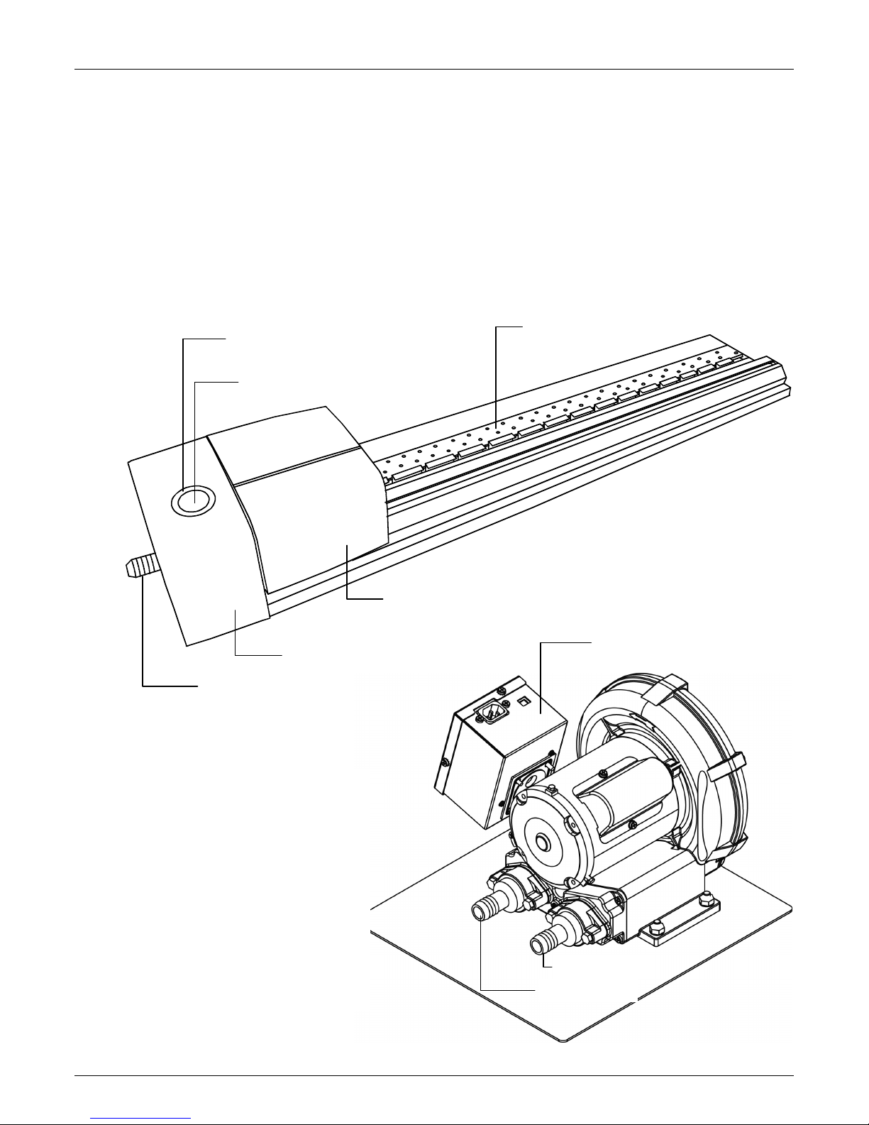
Instrument Description
The IntelliTrax™ series of autoscanning instruments provide fast, press-side color control.
The instruments give you everything you need to maximize productivity and profitability
during sheetfed, makeready and production.
This manual covers the installation, basic operation and maintenance of the instrument.
Specific instructions for using the instrument with your IntelliTrax software application can
be found in the software online help.
Instrument Indicator
(surrounds operation button)
Operation Button
Docking station
Vacuum connection
Scanning read head
Scanning track with vacuum
holes and sheet stops
Control box
Vacuum Pump
A series of small holes located
in the surface of the track are
used to hold the press sheet in
place during a measurement.
This is accomplished by the use
of a vacuum pump. The vacuum
pump is connected to the
docking station, allowing
automatic activation during a
measurement cycle.
4
Exhaust port
Vacuum inlet port
Page 7
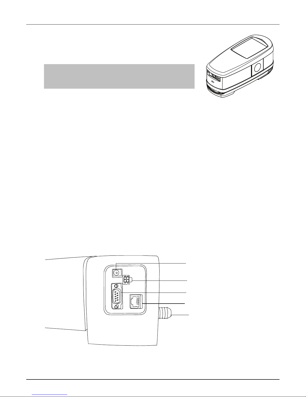
eXact Handheld Spectrophotometer
(Optional Accessory)
The optional hand-held spectrophotometer supplied with
your system allows you to take spot check measurements.
NOTE: It is recommended that you read the Hand-held
Instrument Manual supplied with your system before using
the hand-held instrument.
Unpacking and Inspection
After removing the instrument from the shipping carton, inspect it for damage. If any
damage has occurred during shipping, immediately contact the transportation company. Do
not proceed with installation until the carrier’s agent has inspected the damage.
Your instrument was packaged in a specially designed carton to assure against damage. If
shipment is necessary, the instrument should be packaged in the original carton along with
all the accessories. If the original carton is not available, contact X-Rite to have a
replacement shipped to you.
Packaging Contents:
• IntelliTrax Instrument
• Vacuum Pump
• eXact Handheld Instrument (optional accessory)
• Cabling
• Switching Power Supplies with line cords
• Getting Connected Sheet
• Documentation Package (software CD, manual, registration form, cert of cal)
INTELLITRAX® AUTOSCANNING SYSTEM
System Connections
The IntelliTrax system requires a few basic connections before operating. Connection
procedures for the individual components are covered on the following pages.
Power Input
Vacuum Pump
Not used
Ethernet
Vacuum Pump Hose
Docking Station
5
Page 8
INTELLITRAX® AUTOSCANNING SYSTEM
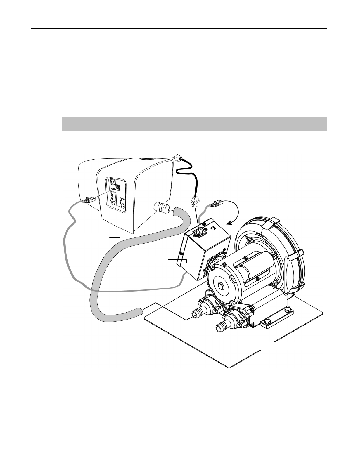
Vacuum Pump Connections
1. Connect one end of the vacuum hose (1) to the barbed input fitting located on the
vacuum pump, and the other end to the barbed fitting on the side of the docking station.
2. Plug one end of the vacuum cable (2) into the connecter on the control box (3) and the
other end into the connector on the back of the docking station.
3. Make sure the voltage selection switch (4) on the top of the control box (3) is set to the
proper line voltage for your region.
4. Connect the detachable line cord (5) to the control box (3), and then plug the line cord
into an easily accessible, grounded AC wall receptacle (6).
NOTE: To obtain 15% more vacuum from the pump, remove the exhaust barbed
adapter (7).
Vacuum Cable (2)
To AC Wall
Receptacle (6)
Line Cord (5)
Voltage Selection
Switch (4)
Vacuum Hose (1)
Control Box (3)
Computer/Monitor Installation
If the system you purchased included a computer and monitor, refer to the documentation
that is included with those products for specific installation procedures.
6
Exhaust Barbed Adapter (7)
Page 9

INTELLITRAX® AUTOSCANNING SYSTEM
Ethernet Interface Connection – system default standalone configuration
The supplied Crossover Ethernet cable should be connected before applying power to the
docking station. The Ethernet port is located on the back of the docking station. Plug one
end of the Ethernet crossover cable into the Ethernet port on your computer. Plug the other
end of the cable into the docking station.
NOTE: The IntelliTrax hardware
default IP address is as follows:
IP Address: 172.16.1.100
SubNet Mask: 255.255.255.0
To use the system as a standalone
configuration you must set the
computers TCP/IP to the following
IP Address: 172.16.1.1
SubNet Mask: 255.255.0.0
Ethernet Cable
Power Connection
The IntelliTrax system must be allowed to stabilize at room temperature before plugging the
power supply into as AC wall receptacle.
NOTE: This product is intended to be supplied by a listed direct plug-in power supply,
marked “class 2” or “LPS”, rated for 24VDC, 3.0A.
1. Plug the input connector (1) from the AT240-109 24V switching power supply (2) into
the proper location on the back of the docking station.
2. Plug the detachable line cord (3) into the power supply (2), and then plug the line cord
into an easily accessible, grounded AC wall receptacle (4).
Input Connector (1)
AT240-109 24V
Power Supply (2)
To AC Wall
Receptacle (4)
Line Cord (3)
7
Page 10

INTELLITRAX® AUTOSCANNING SYSTEM
Connecting the Optional eXact Handheld Instrument
Operational hazard exists if an AC adapter other than X-Rite SE30-177 is used.
AC Adapter Ratings, Input: 100-240V 50-60 Hz, Output: 12VDC @ 2.5A
1. Turn the docking station over and feed the small plug from the power supply through
the strain relief (1) in the middle of the station.
2. Plug the small plug into the input connector (2). The power supply cable can be feed
out any side of the docking station at the bottom.
3. Plug the detachable line cord in the power supply, and then plug the line cord into an
easily accessible, grounded wall receptacle.
4. Position the instrument on the docking station to charge.
(2)
(1)
5. Plug the square end of the USB cable into the back of the instrument (3).
6. Plug the USB cable into an available port on your computer.
(3)
NOTE: If available, the instrument uses Bluetooth
®
technology and can communicate
wirelessly with your computer. Data from the instrument can be transmitted to the
application. Connecting a USB cable to the instrument disables the wireless connection.
Refer to the instrument manual for additional information on setting up the wireless
function.
8
Page 11

IntelliTrax Software
System Requirements
• 2 GHz computer processor, 3 GHz recommended
• 1 GB minimum, 2 GB recommended
• Microsoft
• 100 GB hard drive or higher
• 15” touch-screen monitor with 1024 x 768 resolution minimum,
17” touch-screen monitor with 1280 x 1024 resolution recommended
• Network card
Installing the IntelliTrax Software
NOTE: Shut down the Windows firewall and any anti-virus software you may be running. If
you are reinstalling or updating the software, you must first uninstall the current version of
IntelliTrax from your computer. This will not delete any of your stored database files. All
information will be retained.
The IntelliTrax software uses a standard Windows installation procedure.
1. Insert the IntelliTrax CD into your computer’s CD-ROM drive. The setup program will
start automatically. If the install program does not start automatically, click the Windows
Start button, then choose Run from the start menu. In the Run dialog box, type
d:\setup.exe (where “d” is your computer’s CD-ROM drive). Click OK.
2. The setup program guides you though the rest of the installation process. Follow the
instructions on each setup screen to complete the installation.
3. Refer to the IntelliTrax online help system for information on operation of the software.
NOTE: IntelliTrax uses a free version of SQL Server. This version is fully functional with a
few limitations. Please refer to the online help in the Database Administration Tool for more
information.
®
Windows XP Professional SP2 or Windows 7 32-bit and 64-bit, Windows 8
INTELLITRAX® AUTOSCANNING SYSTEM
Installing the Color Reflectance Reference Data
The color reflectance reference data must be installed on your computer to allow you to
measure the color reference.
1. Insert the Color Reflectance Reference Data CD into your computer’s CD-ROM drive to
automatically install the file. If the file does not automatically install, double-click on the
Install.exe file located on the CD.
2. Refer to IntelliTrax Color Reference Measurement procedure in the Appendices for
additional information.
Instrument Indicator
The instrument indicator that surrounds the operation button conveys a variety of
instrument conditions. Below is a list of conditions reported by the instrument indicator.
• Solid Green—indicates that the scanning head is docked and ready for use.
• Solid Orange—indicates that the scanning head is away from the docking station.
• Solid Red—indicates that the instrument hardware is not ready and a problem may exist
with the system.
• Flashing Green—indicates that the instrument is taking a reading, status OK.
• Flashing Orange—indicates that the instrument is calibrating.
• Flashing Red—indicates that the network is not ready.
• Alternating Red and Green—indicates that a measurement error has occurred when the
scanning head is docked.
9
Page 12

INTELLITRAX® AUTOSCANNING SYSTEM
Operating the System
Sheet Loading and Alignment
You should refer to the online help in the software application for procedures on creating
and selecting color bars. The following information is provided to familiarize you with the
mechanical aspects required when measuring.
Loading a press sheet onto the IntelliTrax is fast and easy, there are no guides or clamps to
adjust. The press sheet is loaded onto the track from the back, and held in place by a series
of vacuum holes.
The press sheet must be positioned between the scribe lines on the track for a valid
measurement to occur.
The press sheet must also be positioned against the “sheet stops” that run along the back
edge of the vacuum plate. The color bar on the sheet must be within 38 mm (1.5”) from the
paper’s edge.
Scribe line
Vacuum holes
Sheet stop
Scribe line
Maximum 38 mm (1.5”)
from paper edge
Scribe line
10
Page 13

INTELLITRAX® AUTOSCANNING SYSTEM
Measuring with the IntelliTrax System
After the press sheet is positioned on the track, you are ready to perform a color bar
measurement. A measurement is started one of two ways:
• selecting the measurement function from the software
• pressing the Operation button located on top of the docking station
Refer to the online help in the software for additional information.
In the event that a color bar is crooked or fanned out, the scanning system incorporates a
“look-ahead sensor” that takes corrective action by automatically adjusting the scanning
head. This ensures all color patches are measured accurately.
Once a measurement is set in motion, the vacuum solenoid activates and the “green” light
on the station changes to “flashing green”, indicating a scan is in progress. Measurement
results are reported real-time to the computer monitor.
The vacuum pump can be turned off during non-use times by selecting the “Turn off
vacuum” option in Press Tool. Refer to the online help system for further details.
If a problem is encountered during a measurement, the scanning head immediately returns
to the docking station. View your computer monitor to see if an error message is displayed.
If no message is displayed, try to rescan the sheet; if a problem still occurs, refer to the
Troubleshooting section in this manual.
NOTE: You can abort a measurement by pressing the Operation button when the
instrument is scanning the color bar.
Press the Operation button
to start a measurement
11
Page 14

INTELLITRAX® AUTOSCANNING SYSTEM
Calibration
Regular calibration of the IntelliTrax system and hand-held instrument is important for
maintaining accurate and consistent measurement data. Normally, the software application
prompts you for a calibration when it’s required. Calibration of either the IntelliTrax system
or hand-held instrument can also be manually invoked whenever desired.
Calibrating the IntelliTrax System
Calibrating the scanning instrument is virtually automatic. A white calibration disk is a
permanent part of the track assembly, located near the docking station. A retractable cover
protects the calibration disk when the scanning head is away from the docking station. The
scanning head automatically calibrates to the white disk when required, or when calibration
is initiated in the application.
IMPORTANT: The white calibration disk should be cleaned periodically to maintain
calibration accuracy. Refer to Cleaning the White Calibration Disk in the Appendices for the
procedure.
Calibration Disk Cover
12
Page 15

INTELLITRAX® AUTOSCANNING SYSTEM
Calibrating the Optional eXact Handheld Instrument
IMPORTANT: The calibration plaque is dramatically affected by smudge marks and dust,
and must be kept clean. It is recommended that the instrument is cleaned regularly. Refer
to the cleaning procedure below.
The instrument has an integrated calibration plaque and will calibrate automatically when
required. When calibration is required before a measurement, the instrument will prompt
you. This occurs when the instrument is in the open position (not locked) and the previous
calibration has timed out. This can also occur when the measurement condition switch is
changed and a calibration has not been performed in that position or has timed out.
When prompted for a calibration, locate the instrument on a flat surface and tap the START
button. The instrument will display a countdown screen and then perform the calibration.
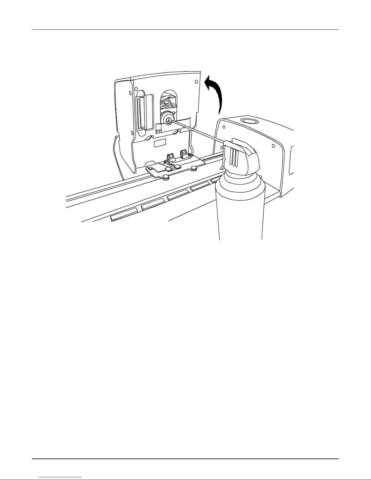
Cleaning the Calibration Plaque
The calibration plaque should be cleaned periodically.
Do not use solvents or cleaners of any kind.
The calibration tile is embedded in the underside of the reference holder.
1. Rotate the reference holder (1) towards the back and hold.
2. Blow short bursts of clean, dry air (2) onto the calibration tile. This should remove any
accumulated debris.
(1)
(2)
3. Carefully return the calibration holder to its normal position.
13
Page 16

INTELLITRAX® AUTOSCANNING SYSTEM
Measuring with the eXact Handheld
The Handheld instrument can be used to measure ink colors and make spot check
measurements as needed. The target base of the instrument should rest flat and steady on
the sample area.
1. Position the target window over the sample to measure. The opening should be
completely filled with the sample color.
2. Press the instrument firmly to the target base. Measuring appears in the display along
with the Measurement Condition selected.
3. Hold steady until “Complete!” and measurement data is displayed. This is an indication
that the measurement was successful.
If the instrument is moved during measurement or is not held closed for the entire
measurement, no data will display on the computer monitor. Simply take another
measurement if this occurs.
14
Page 17

Appendices
Service Information
The IntelliTrax System is covered by a one-year limited warranty and should be referred to
an authorized service center for repairs within the warranty period.
X-Rite provides repair service to their customers. Because of the complexity of the circuitry,
all repairs should be referred to an authorized service center.
X-Rite will repair any instrument past warranty. The customer shall pay shipping and repair
cost to the authorized service center. The instrument shall be submitted in the original
carton, as a complete unaltered unit along with all the supplied accessories.
Troubleshooting
Prior to contacting X-Rite’s Customer Service for instrument problems, try the applicable
solution(s) described below. If the condition persists, contact X-Rite Customer Service by
phone at 1-888-826-3059; by fax at 1-888-826-3061; or by email at gisupport@xrite.com.
Additional X-Rite office numbers are located on the back cover of this manual. You can also
visit X-Rite’s Support page at www.xrite.com
desk questions.
INTELLITRAX® AUTOSCANNING SYSTEM
; here you can find answers to common help
Scanning instrument indicator not illuminating:
• Ensure that the power supply is plugged in.
• Reset the instrument (see Instrument Reset).
Solid red scanning instrument indicator:
• An error or problem exists with the system.
• Remove power from the instrument, reapply power and see if the condition is corrected.
• Reset the instrument (see Instrument Reset).
Scanning instrument and software not communicating:
• Check Ethernet cable for proper connection.
• Close the software application, cycle power on the instrument and restart the software
application. If this does not work reboot the computer.
• If system is networked, contact your network administrator for possible Ethernet issues.
• Reset the instrument (see Instrument Reset).
Scanning instrument Calibration fails:
• Ensure that the calibration references and instrument optics are clean (see General
Maintenance).
• Close and restart the software application.
• Reset the instrument (see Instrument Reset).
Scanning Instrument Reset
The following procedure performs a hardware reset on the scanning instrument.
1. Make sure the instrument is powered on and the scanning head is docked.
2. Press and hold the Operation button for approximately 10 seconds.
3. The indicator light will change to orange and then back to green. Release the Operation
button when indicator light is back to green.
15
Page 18

INTELLITRAX® AUTOSCANNING SYSTEM
General Maintenance
Your instrument requires very little preventative maintenance to achieve years of reliable
operation. However, to protect your investment and maintain reading accuracy, a few
simple-cleaning procedures should be performed from time to time.
For general maintenance of the hand-held instrument, refer to the documentation that it was
packaged with.
ATTENTION: A properly grounded wrist strap is recommended when cleaning, removing or
installing the scanning head.
Scanning Head Cleaning (1 to 2 times a month)
DO NOT use any solvents or harsh cleaners of any kind.
In the course of normal use, spray powder, paper dust, and other airborne contaminants
will likely enter the instrument's optics. This can eventually reduce the sensitivity of the
instrument and may lead to calibration errors. Follow the steps below to clean the optical
components.
1. Obtain a source of clean, dry, compressed air. This air should be of the quality used to
clean delicate camera lenses.
2. Unplug the IntelliTrax system from the power adapter and slide the scanning head a few
millimeters away from the docking station.
3. Lift the access cover on the back of scanning head to gain access to the locking lever.
4. Rotate the lever 90° clockwise.
Access Cover
5. Lift up under the front edge of the scanning head and tilt it back to expose the bottom.
16
Page 19
INTELLITRAX® AUTOSCANNING SYSTEM
6. Being careful to hold the compressed air source upright, blow short, gentle bursts of
compressed air directly into the instrument's aperture. Be careful to ensure the
compressed air nozzle is approximately 10 mm away from the optics.
7. Carefully lower the scanning head and lock into place by rotating the lever 90°
counterclockwise.
8. Lower the access cover and plug in the AC adapter.
9. Note that the process of cleaning the optics will affect the instrument's sensitivity as
dust and powder will no longer block the optical path. It is essential that a head and
track calibration is done following the cleaning process.
10. The exterior of the scanning head and docking station can be wiped clean with a lint-free
cloth dampened in water or a mild cleaner.
Scanning Track Cleaning (1 to 2 times a month)
DO NOT reverse the intake/exhaust port on the vacuum pump to blow out the track
vacuum chamber. This will force any dust inside the track into the read head optics.
DO NOT use any solvents or harsh cleaners of any kind.
DO NOT use any type of lubrication (oil) on any part of the system.
1. The exterior of the scanning head and docking station can be wiped clean with a lint-free
cloth dampened in water or a mild cleaner.
2. The track should be wiped clean with a lint-free cloth dampened in glass cleaner. When
cleaning the track, make sure to clean the entire track. This includes the portion of the
track that resides under the reading head when it is in its docked position. You can lift
the scanning head (Scanning Head Cleaning for procedure) or simply slide it over when
cleaning is required.
3. Inside the track, use compressed air to remove all print dust.
17
Page 20

INTELLITRAX® AUTOSCANNING SYSTEM
Cleaning the White Calibration Disk
On a daily basis, you will need to clean the white calibration disk located in the track. This is
a relatively easy procedure requiring only a few minutes of time.
1. Unplug the IntelliTrax system from the power adapter and slide the scanning head away
from the docking station.
2. Pull calibration cover towards the docking station to expose the white disk.
3. Clean the white calibration disk with a cotton swab or lint free cloth.
4. Blow off the disk with compressed air.
5. Blow out under the calibration cover with compressed air.
6. Carefully release calibration cover and slide scanning head back against docking station.
Cotton Swab
Calibration Cover
Calibration Disk
Scanning Head
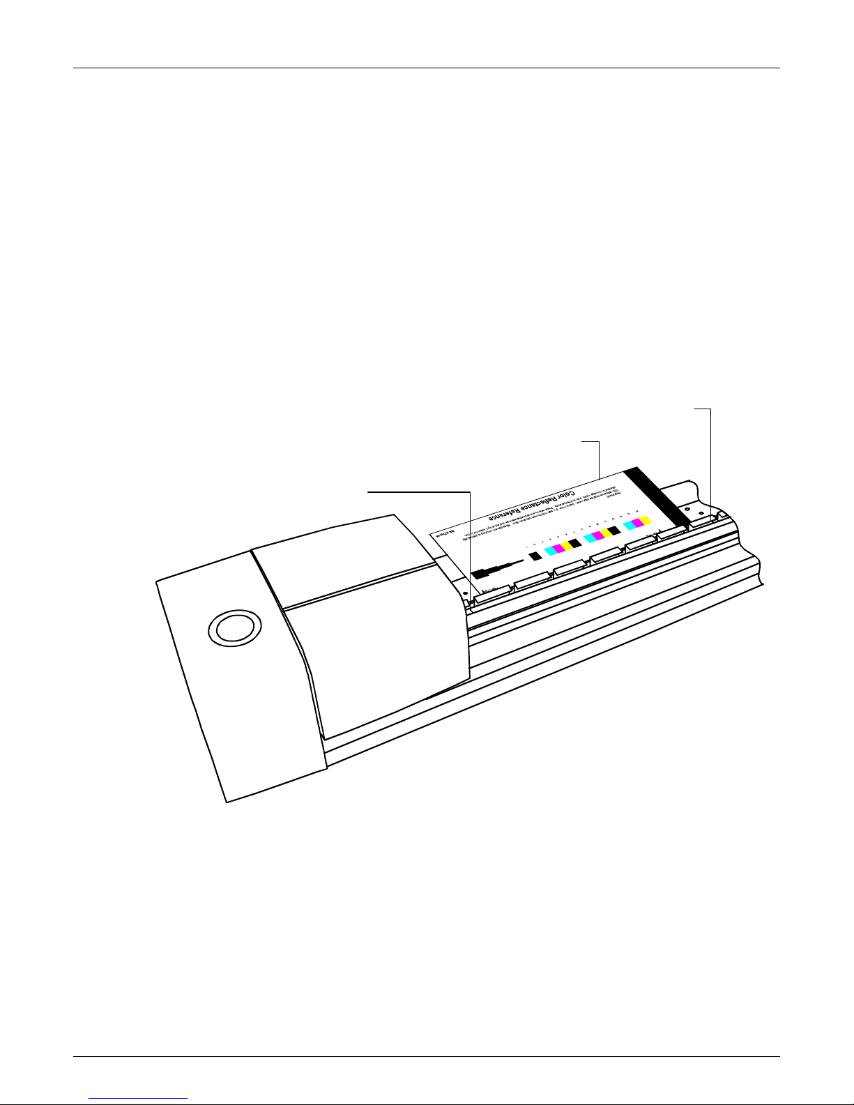
Cleaning the Color Reflectance Reference
The color reflectance reference is dramatically affected by smudge marks, dust, and fingers
prints. The reference can be cleaned with a lint free cloth whenever required. Make sure to
return the reference to its protective envelope when finished.
13
1415
Important:
This reference must be kept clean. Use a clean, dry, soft cloth to wipe reference clean. Measurement accuracy is dramatically
affected by smudge marks, dust and temperature. Place reference in protective envelope an d out of light when not in use.
18
123456789101112
P/N AT240-64
Page 21

Removing the Scanning Head
The following procedure explains how to remove the scanning head in the event
maintenance is required.
1. Unplug the IntelliTrax system from the power adapter and slide the scanning head at
least 5 inches (127 mm) away from the docking station.
2. Lift the access cover on the back of scanning head to gain access to the locking lever.
3. Rotate the lever 90° clockwise.
4. Compress the two locking tabs located on both sides of the scanning head connector. It
may be helpful to use a pair of needle-nose pliers to gain access to the locking tabs.
5. Pull the connector outwards to free it from the scanning head.
INTELLITRAX® AUTOSCANNING SYSTEM
Access Cover
Scanning Head Connector
6. Lift up under the front edge of the scanning head and tilt it back to expose the bottom.
7. Holding the scanning head with one hand, carefully remove the four Phillips-head screws
securing the scanning head to the trolley.
Screws (2)
Screws (2)
8. Lift the scanning head free from the trolley.
19
Page 22
INTELLITRAX® AUTOSCANNING SYSTEM
IntelliTrax Color Reference Measurement Procedure
The color reference measurement procedure provides you with a method to check the
performance of your IntelliTrax instrument. A color reference measurement can be
performed at anytime.
NOTE: Use must have the Color Reflectance Reference Data installed on your computer to
perform this measurement procedure.
1. Remove the color reflectance reference from its protective envelope. Make sure that it is
clean before continuing with the measurement procedure. If the color reflectance
reference requires cleaning, refer to the Cleaning the Color Reflectance Reference
explained earlier.
2. Position the color reflectance reference on the track, next to the scribe line by the
scanning head. Make sure the designated side of the reference is positioned up against
the sheet stops.
3. Start the measurement sequence by selecting the Measure Color Reference button in
the Press Tool. View the monitor for measurement results.
Color Reflectance Reference
Sheet Stops
Scribe line
4. Select the appropriate option in application to start the calibration check. The scanning
head moves across the color reflectance reference and then back to its docked position.
The indicator light flashes green during the reading and then turns to solid green after a
successful reading. This is also verified on the computer monitor.
If the calibration check fails (indicated on the computer monitor), clean the color
reflectance reference and instrument optics as explained earlier, and perform the
calibration check again. If the calibration check fails again, contact your X-Rite
representative. You may need to replace your color reflectance reference (Part Number
ATS40-64).
5. Return the color reflectance reference back to its protective envelope.
20
Page 23

Instrument Specifications
General
Measurement Geometry: ........ Reflection 45°/0° per ANSI PH2.17
Aperture Configurations .......... Small, Medium, and Medium w/polarization
Light Source: ........................ Gas pressure @ 2850°K
Spectral Sensor: .................... DRS Technology (31pt)
Spectral Range: .................... 400 – 700 nm
Reflectance Range: ................ 0 - 150% R
Density Range: ..................... 0 - 2.5D for Medium and Small Spot
Repeatability on White: .......... 0.2 ΔE max.; ±0.01D max.
Density Reproducibility: .......... Cyan, Magenta, and Visual Filters
Calibration: .......................... White calibration reference provided in track
Scan Spot Size
Patch Width
Patch Height: ....................... 3.2 mm min. for Medium Spot
Paper Thickness: ................... 0.030 in. (0.762 mm) max Medium and Polarized Spot
Scanning Rate: ..................... 2 in. (50 mm)/Second on a 3.0 mm Patch for Medium
Track Lengths: ...................... 40 in. (1016 mm) standard, 29 in. (736.6 mm),
Color Bar Location: ................ Entire color bar within 1.5 in. (38 mm) of edge
Color Bar Alignment: .............. Automatic centering of measurement on color bar
Color Bar Quantity: ................ 1 row per paper surface
Paper Hold Down: .................. Vacuum activated with measurement command
Power Required: .................... 100-240VAC, 50-60Hz
(along scan path): ........ 3.0 mm min. for Medium and Small Spot
INTELLITRAX® AUTOSCANNING SYSTEM
0 – 3.0D for Polarized Spot
±0.02D @ 1.5D
Yellow Filter
±0.02D @ 1.5D for a non DP scanning head
±0.03D @ 1.5D for a DP scanning head
(total scanned spot): . 2.3 mm x 2.75 mm min. for Medium Spot
1.2 mm x 2.75 mm min. for Small Spot
2.7 mm x 3.20 mm min. for Polarized Spot
3.5 mm min. for Polarized Spot
2.0 mm min. for Small Spot
3.5 mm min. for Polarized Spot
0.020 in. (0.508 mm) max Small Spot
and Small Spot
2.3 in. (58 mm)/Second on a 3.5 mm Patch for
Polarized Spot
32 in. (812.8 mm) 65 in. (1651 mm), and
80 in. (2032 mm)
Paper set against stops
Environmental
Operating Temp: ................... +10° (50°F) to +35°C (95°F)
Humidity Range: ................... 0 - 85% RH non-condensing
Storage Temp: ...................... -20°C to +50°C
Usage: ................................. Indoor Only
Design and specifications subject to change without notice.
21
Page 24

Corporate Headquarters
X-Rite, Incorporated
4300 44th Street SE
Grand Rapids, Michigan 49512
Phone 1 800 248 9748 or 1 616 803 2100
Fax 1 800 292 4437 or 1 616 803 2705
European Headquarters
X-Rite Europe GmbH
Althardstrasse 70
8105 Regensdorf
Switzerland
Phone (+41) 44 842 24 00
Fax (+41) 44 842 22 22
Asia Pacific Headquarters
X-Rite Asia Pacific Limited
Suite 2801, 28th Floor, AXA Tower
Landmark East, 100 How Ming Street
Kwun Tong, Kowloon, Hong Kong
Phone (852) 2568 6283
Fax (852) 2885 8610
Please visit www.xrite.com
for a local office near you.
P/N AT240-500 Rev. H
 Loading...