

Page 1
DensiEye
™
Reference Manual
E N G L I S H
Page 2

X-Rite DensiEye 100 and 700
Contents
1. General ................................................................................................................................... 3
1.1. Introduction ........................................................................................................................... 3
1.2. Safety instructions ................................................................................................................. 4
1.3. Package contents .................................................................................................................. 5
1.4. Packaging and transport ....................................................................................................... 5
2. Operation ................................................................................................................................ 6
2.1. Functional elements .............................................................................................................. 6
2.2. Release and lock measuring head ........................................................................................ 6
2.2.1. Release measuring head ............................................................................................................... 6
2.2.2. Lock measuring head .................................................................................................................... 6
2.3. Factory settings ..................................................................................................................... 7
2.4. Standard buttons ................................................................................................................... 8
2.5. Special buttons and button combinations ............................................................................. 8
2.6. Symbols and their functionality ............................................................................................. 9
2.7. Display and Pass/Fail indicator ........................................................................................... 10
2.7.1. Display layout .............................................................................................................................. 10
2.7.2. Message box ............................................................................................................................... 10
2.7.3. Pass/Fail indicator ....................................................................................................................... 10
2.7.4. Pass/Fail information ................................................................................................................... 11
2.8. Function selection ............................................................................................................... 11
2.9. Symbol selection ................................................................................................................. 11
2.10. Positioning and measurement ............................................................................................. 11
3. Measurement Functions ..................................................................................................... 12
3.1. Auto Mode ........................................................................................................................... 12
3.2. Density ................................................................................................................................ 14
3.2.1. Density (Paper) ............................................................................................................................ 14
3.2.2. Density (Absolute) ....................................................................................................................... 15
3.3. Dot Gain .............................................................................................................................. 16
3.4. Trapping .............................................................................................................................. 18
3.5. Gray Balance ...................................................................................................................... 19
3.5.1. Gray Balance (Paper) .................................................................................................................. 19
3.5.2. Gray Balance (Absolute) .............................................................................................................. 20
3.6. Dot Area .............................................................................................................................. 21
3.7. Print Characteristic .............................................................................................................. 22
4. References ........................................................................................................................... 24
4.1. Select a reference set ......................................................................................................... 24
4.2. Solid reference .................................................................................................................... 25
4.2.1. Measure Solid reference values (Paper) ...................................................................................... 25
4.2.2. Edit Solid reference and tolerance values (Paper) ...................................... ................................. 25
4.2.3. Measure Solid reference values (Absolute) ................................................................................. 26
4.2.4. Edit Solid reference and tolerance values (Absolute) ................................................................... 26
4.3. Halftone and Dot Gain ......................................................................................................... 27
4.4. Gray Balance ...................................................................................................................... 28
4.4.1. Measure Gray Balance reference values (Paper) ........................................................................ 28
4.4.2. Edit Gray Balance reference and tolerance values (Paper) ......................................................... 29
4.4.3. Measure Gray Balance reference values (Absolute) .................................................................... 29
4.4.4. Edit Gray Balance reference and tolerance values (Absolute) ..................................................... 30
5. Calibration ............................................................................................................................ 31
5.1. Calibration (paper white base) ............................................................................................ 31
5.1.1. Select paper white base ............................................................................................................... 31
5.1.2. Calibration (Paper) ....................................................................................................................... 32
5.1.3. Check Calibration (Paper) ............................................................................................................ 32
5.2. Calibration (absolute white base) ........................................................................................ 33
5.2.1. Select absolute white base .......................................................................................................... 33
5.2.2. Calibration (Absolute) .................................................................................................................. 34
5.2.3. Check Calibration (Absolute) ....................................................................................................... 34
5.3. Density calibration reference ............................................................................................... 35
DensiEye Ref erence Manual 4 1
Page 3

X-Rite DensiEye 100 and 700
6. Settings ................................................................................................................................. 36
6.1. Function settings ................................................................................................................. 36
6.1.1. Pass / Fail indicator ..................................................................................................................... 36
6.1.2. White base ................................................................................................................................... 37
6.1.3. Scale graduation .......................................................................................................................... 38
6.1.4. Decimal places ............................................................................................................................ 38
6.2. Device settings .................................................................................................................... 39
6.2.1. Turn display ................................................................................................................................. 39
6.2.2. Instrument type ............................................................................................................................ 39
6.2.3. Language ..................................................................................................................................... 40
7. USB Interface ....................................................................................................................... 41
7.1. USB Driver Installation ........................................................................................................ 41
7.2. USB Interface Protocol ........................................................................................................ 41
8. DensiEye 100 to 700 Upgrade ............................................................................................. 41
9. Maintenance and Care ......................................................................................................... 43
9.1. Reset ................................................................................................................................... 43
9.2. Total Reset .......................................................................................................................... 43
9.3. Instrument type information ................................................................................................. 44
9.4. Replacing the batteries ....................................................................................................... 45
9.5. Firmware upgrade ............................................................................................................... 46
9.6. Warranty registration ........................................................................................................... 47
9.7. Recertification ..................................................................................................................... 47
9.8. Service ................................................................................................................................ 47
10. Specifications ...................................................................................................................... 48
10.1. Functions ............................................................................................................................. 48
10.2. Technical Specification ....................................................................................................... 48
2 DensiEye Reference Manual 4
Page 4

X-Rite DensiEye 100 and 700
1. General
1.1. Introduction
Dear Customer
Congratulations! You have just acquired the reflection densitometer DensiEye.
The DensiEye features an easy to use graphical user interface and a high level of automation.
Its high measurement accuracy makes this a truly unique instrument.
In this reference manual, all functionality of the DensiEye 100 and DensiEye 700 is explained
in step by step detail. For a quick first start, please refer to the quick start guide, which enables
you to use your new instrument immediately.
Your X-RiteTeam
DensiEye Ref erence Manual 4 3
Page 5

X-Rite DensiEye 100 and 700
1.2. Safety instructions
The X-Rite DensiEye is not for use in an explosive environment
Do not expose the DensiEye to strong electromagnetic fields.
For safety reasons, the DensiEye should be operated at ambient temperatures between
10°C / 50°F and 40°C / 104°F with a relative air humidity of 20% to 80% (non-condensing).
For safety reasons, the DensiEye should be stored at ambient temperatures between 20°C /- 4°F and 70°C / 158°F with a relative air humidity of 5% to 90% (non-condensing).
Do not expose the DensiEye to direct sunlight.
Protect the DensiEye against chemical substances, corrosive vapors, strong vibrations,
and mechanical influences.
Always use the original packaging to transport the DensiEye.
Do not attempt to repair the DensiEye. Opening the instrument will void your warranty.
Only use genuine X-Rite accessories and spare parts
DensiEye should only be used by trained personnel
Always place samples on a stable measuring surface. Make sure the bottom of the shoe is
flat against the measurement surface.
The plastic device casing can be cleaned using a damp cloth and a small amount of soap
Never short-circuit the batteries!
Always replace both batteries at the same time
Dispose of batteries in accordance with local regulations
4 DensiEye Reference Manual 4
Page 6
X-Rite DensiEye 100 and 700
1.3. Package contents
Item Name
1 DensiEye
2 Calibration card
3 USB cable
4 Quick start guide
5 Device certificate
6 Registration card
7 CD with operating instructions and software
8 Device case
1.4. Packaging and transport
Always use the original packaging to transport the DensiEye.
DensiEye Ref erence Manual 4 5
Page 7
r
X-Rite DensiEye 100 and 700
2. Operation
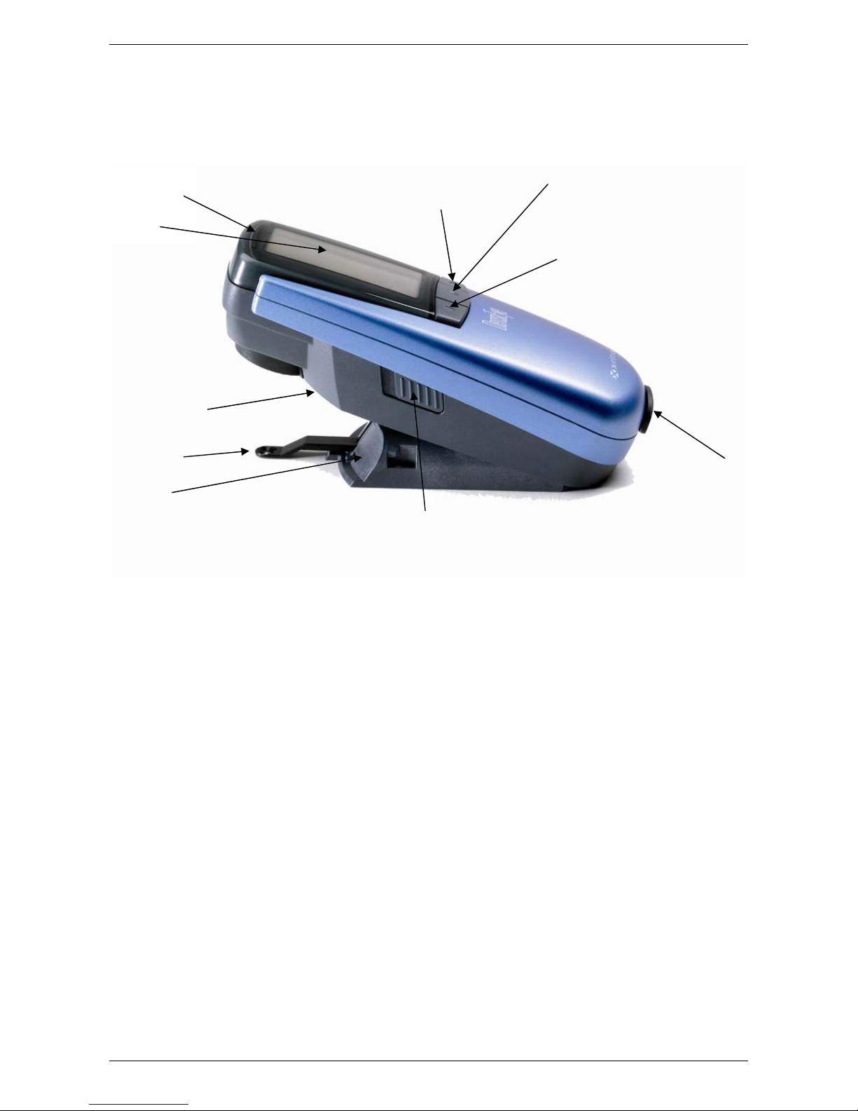
2.1. Functional elements
PASS/FAIL
Indicator
Display
Reset button
Measuring
diaphragm
Batteries
Up button
Locking button
Ente
button
Down button
USB Interface
2.2. Release and lock measuring head
2.2.1. Release measuring head
• Slide the locking button on the left side to the back to release the measuring head.
• After approximately 30 seconds of inactivity, the DensiEye goes into power saving
mode.
• Press any button to wake up the instrument.
2.2.2. Lock measuring head
• Lower the measuring head and slide the locking button forward to lock the measuring
head
• After approximately 30 seconds of inactivity, the DensiEye goes into power saving
mode
6 DensiEye Reference Manual 4
Page 8

X-Rite DensiEye 100 and 700
2.3. Factory defaults
• Absolute/Difference values: Absolute
• White base: Paper
• Reference set: 1 reference set
• Filter/color selection: Auto
• Pass/Fail indicator: Off
• Scale graduation for print characteristic: 10%
• Number of decimal places for densities: 2
• Language: English
• Left/right-handed operation: Right-handed operation
DensiEye Ref erence Manual 4 7
Page 9
X-Rite DensiEye 100 and 700
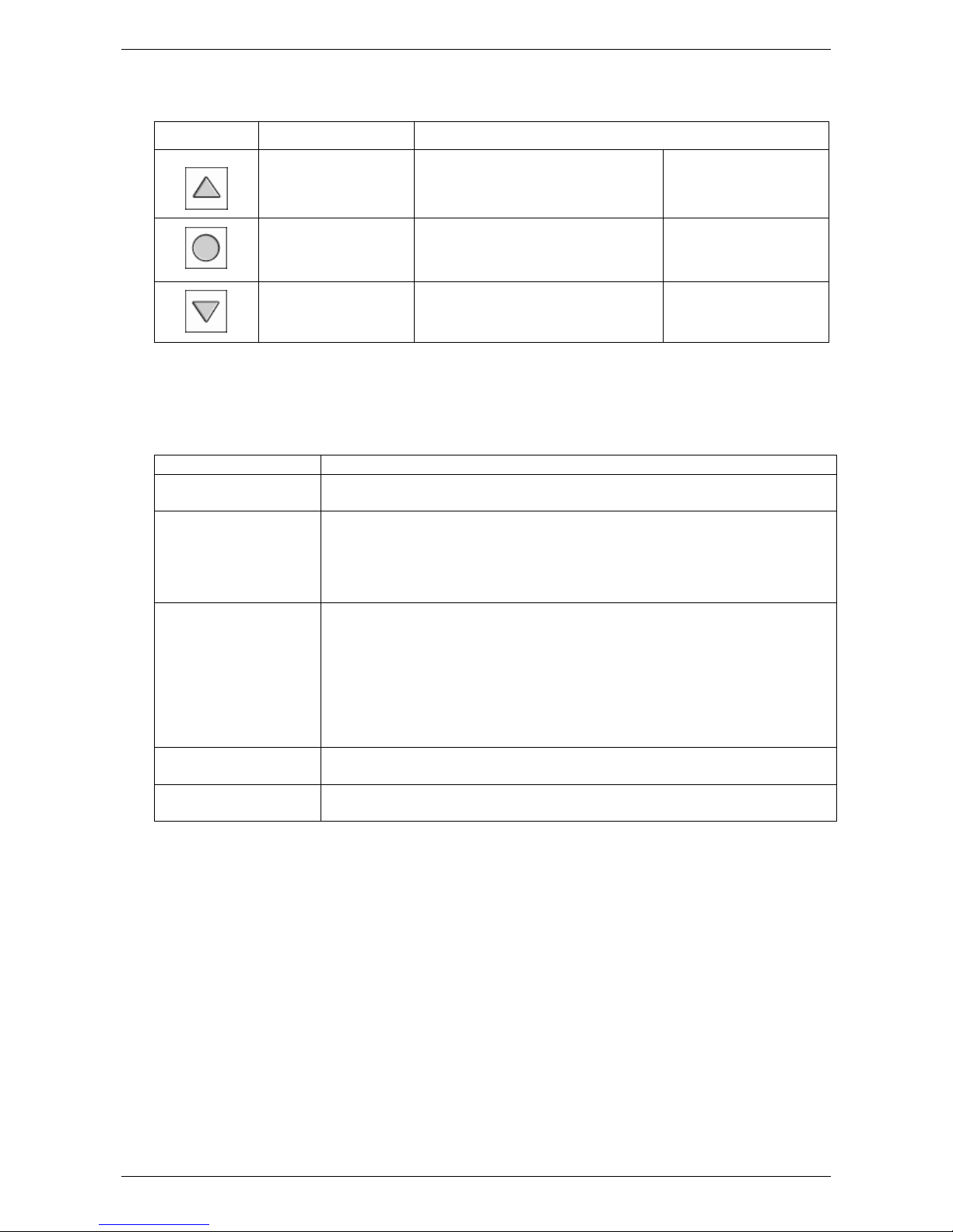
2.4. Standard buttons
Button Description Functionality
Up button Moves cursor up Increase value
Open / close submenu
Enter button
Toggle options
Down button Moves cursor down Decrease value
Confirm value
2.5. Special buttons and button combinations
Button(s) Description
Enter + Measure
Reset Auto mode (DensiEye 700) or Density (DensiEye 100) is selected in
Reset + Enter 2 Auto Mode function is pre-selected in the main menu
1
White measurement
the main menu
All settings are retained
All settings are reset to factory settings
The reference- and tolerance values are retained
The calibration is reset. The device must be re-calibrated
Enter (3 sec) Return to Function Selection on the main menu
Enter (10 sec) Displays the language selection menu
Note:
1
Sequence:
• Press the Enter button
• Execute a white measurement
• Release the Enter button
2
Sequence:
• Press the Reset button
• Press the Enter button
• Release the Reset button
• Release the Enter button
8 DensiEye Reference Manual 4
Page 10
X-Rite DensiEye 100 and 700
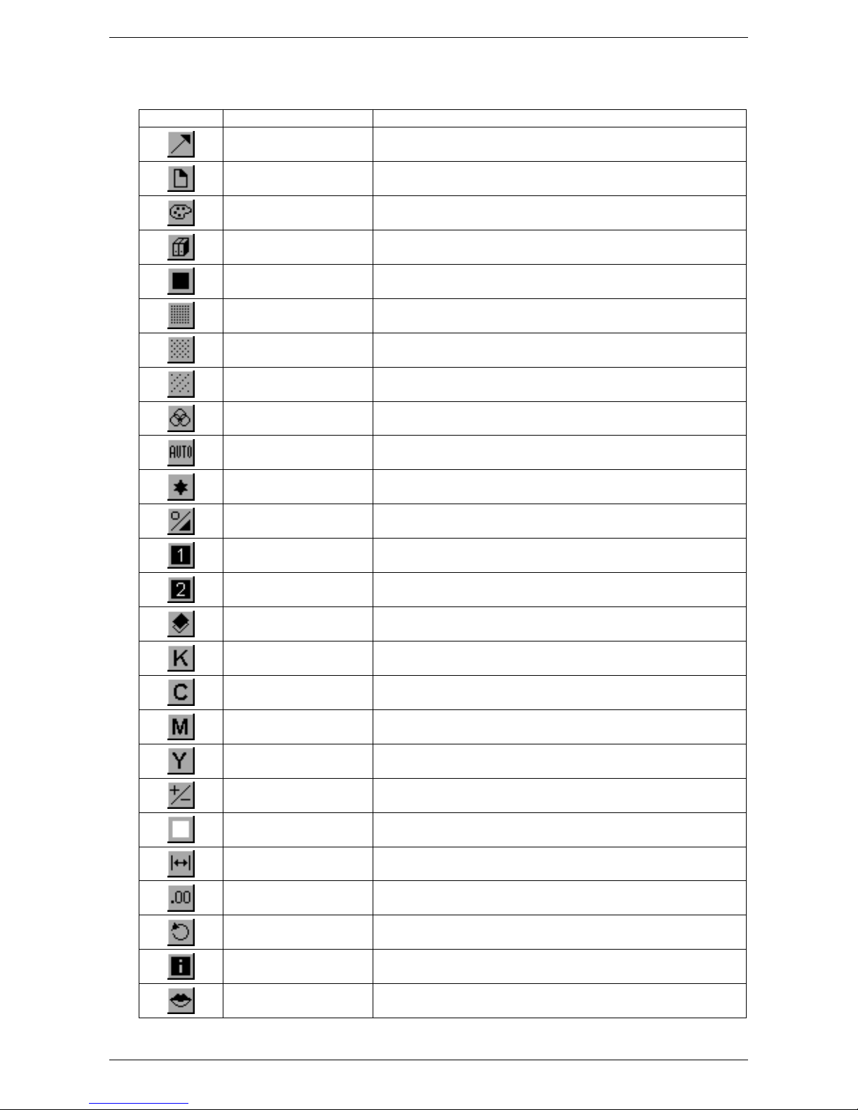
2.6. Symbols and their functions
Symbol Name Description
Return Return to next menu level up, accepts data
Paper
Filter selection Select density filter (automatic or manual)
Reference selection Select one of four reference sets
Solid Measure solid patch / Edit or measure solid reference
Halftone 1 Measure halftone 1 / Edit halftone 1 reference
Halftone 2 Measure halftone 2 / Edit halftone 2 reference
Halftone 3 Measure halftone 3 / Edit halftone 3 reference
Gray balance patch
Measure paper white / Measure absolute white
reference (calibration)
Measure gray balance patch / Edit or measure gray
balance reference
Any patch Measure any patch using Auto Mode function
View / Edit mode View and edit halftone measurements
Absolute / Difference
mode
First solid patch Measure first solid patch (trapping)
Second solid patch Measure second solid patch (trapping)
Trapping Measure trapping patch
Black Edit black value (calibration)
Cyan Edit cyan value (calibration)
Magenta Edit magenta value (calibration)
Yellow Edit yellow value (calibration)
Pass/Fail Toggle Pass/Fail indicator on and off
White base Set white base to paper white or absolute white
Toggle between absolute and difference values
Scale graduation Set scale graduation for print characteristics
Decimal places Set accuracy for density measurements
Screen orientation Change screen orientation for right or left hand use
Instrument type Display device type information
Language Select language
DensiEye Ref erence Manual 4 9
Page 11
X-Rite DensiEye 100 and 700
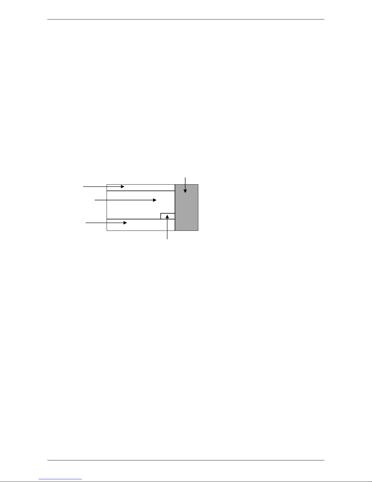
2.7. Display and Pass/Fail indicator
2.7.1. Display layout
The display is divided into 5 areas:
• Header -> Display the name of the basic function
• Help area -> Display help on the specific function
• Symbol area -> Display symbols for navigation via options and menus
• Output area -> Display the measurement results
• Status area -> Display status messages (variable length):
o Selected reference set for difference display
o Selected density filter setting: Auto, Cyan, Magenta,
Yellow or Black
Symbol area
Header
Output area
Help area
Status area
2.7.2. Message box
A message box displays information and error messages for example ”White measurement
done”.
2.7.3. Pass/Fail indicator
The DensiEye has an integrated Pass/Fail indicator. If you take a density, dot gain, or gray
balance measurement, the measurement values are compared to references and
tolerances. The red LED indicates that the measurement is out of tolerance while a green
light indicates the measurement is OK. Settings for the Pass/Fail indicator are in the
function setup.
10 DensiEye Reference Manual 4
Page 12

X-Rite DensiEye 100 and 700
2.7.4. Pass/Fail information display
After setting up reference and tolerance values for density, dot gain (DensiEye 700 only)
and gray balance, the Pass/Fail function can indicate corrective measures to the right of the
measurement values.
• If the measured value is below the specified tolerance range, the instrument displays an
arrow pointing up.
• If the measured value is within tolerance, the instrument displays a check mark behind
the value.
• If the measured value is above the specified tolerance range, the instrument displays
an arrow pointing down.
2.8. Function selection
• Use the Up/Down buttons to select a function from the main menu.
• Press the Enter button in the main menu to open the function screen
• Press the Enter button in a popup window to activate the selected option
2.9. Symbol selection
• Use the Up/Down buttons to select a symbol from the main menu.
• The symbols have different functions (see section Symbols and their functions). Depending
on the function, you need to press the Enter button or initiate a measurement.
2.10. Positioning and measurement
• Always place the printed sheet on a stable measuring surface. Make sure the bottom of the
shoe is flat against the measurement surface.
• Use measuring diaphragm to position the DensiEye properly on the measuring patch
• Lower the measuring head to initiate a measurement
• After the measurement, the instrument displays the measurement values and you can
release the measuring head
DensiEye Ref erence Manual 4 11
Page 13
X-Rite DensiEye 100 and 700
3. Measurement Functions
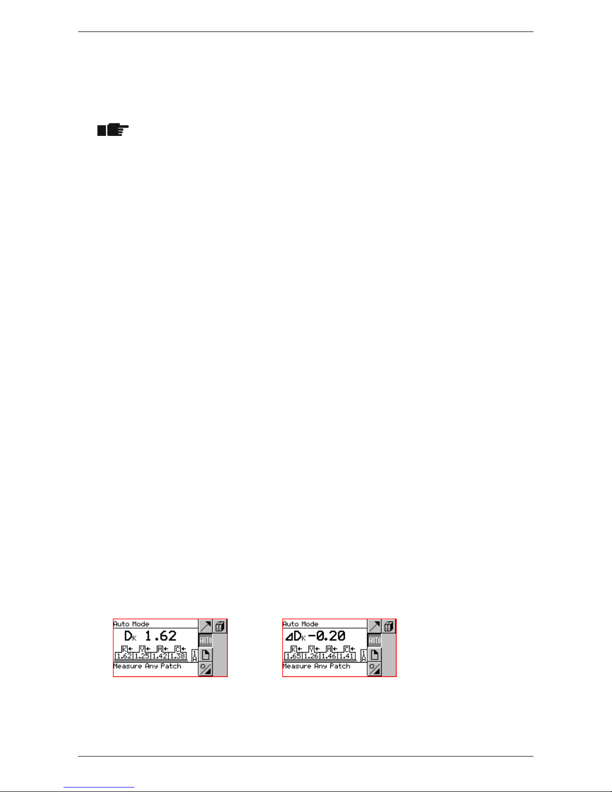
3.1. Auto Mode (DensiEye 700 only)
• The instrument identifies Solid, Halftone, Trapping or Gray Balance patches
automatically and the display shows the corresponding measurement values
• The Paper White measurement is performed automatically if the White Base is
set to Absolute Auto or Paper Auto in the Function Settings.
• The default setting for filter/color detection is the Automatic color/filter detection
• Select reference values in the References menu
• Select the Auto Mode in the main menu
o The status displays the current reference set
o The status displays “A” for automatic filter/color detection
• Select Absolute/Difference
• Select Absolute for absolute measurement values
o The output area displays D
• Select Difference for difference measurement values
o The output area displays ∆D
• Select Reference for difference readings
• The pop-up window shows a list with reference sets
• Select a reference set
o The status area displays the selected reference set
• Select Paper and measure paper white
• After the measurement, the message box briefly displays “White Measurement
done”
• Measure solids in correct printing sequence
• The press icons in the output area show values for the solid densities and the
corresponding colors starting from right to left
• The output area shows absolute or difference values for solid density and the
corresponding color of the last patch:
12 DensiEye Reference Manual 4
Page 14

X-Rite DensiEye 100 and 700
• Measure any patch (Solid, Halftone, Trapping or Gray Balance)
o The output area shows the measurement values of the last patch:
Absolute or difference values for solid density and the corresponding
color
Halftone reference and dot gain value and the corresponding color
Trapping value and the corresponding printing sequence
Absolute or difference values for density for Cyan, Magenta and Yellow
• Select Return to return to the main menu
DensiEye Ref erence Manual 4 13
Page 15
X-Rite DensiEye 100 and 700
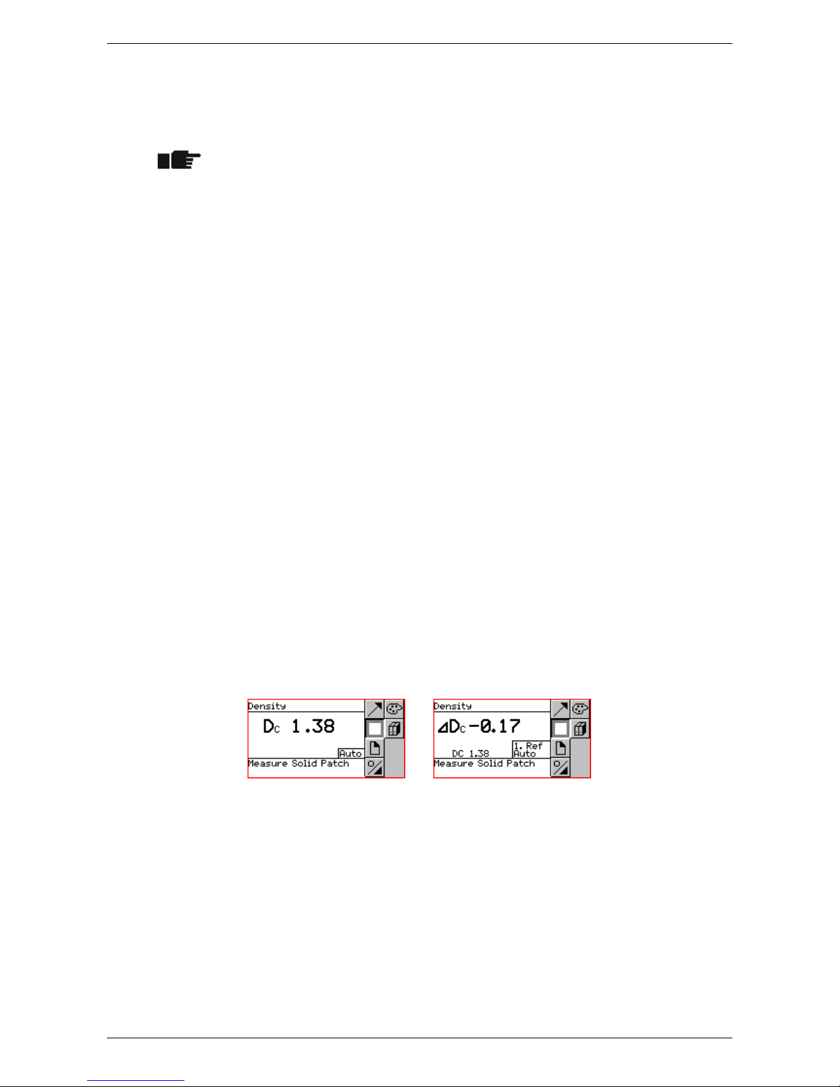
3.2. Density
3.2.1. Density (Paper)
• Set White Base to Paper or Paper Auto in the Function Settings
• Make sure the instrument is calibrated for paper white base
• Set reference values in the References menu
• Select Density in the main menu
o The status displays the current reference set if the Pass/Fail detection is activated
or Absolute/Difference is set to Difference
o The status displays the current filter/color
• Select Filter
• The pop-up window shows a list with automatic or manual filter/color selections
• Set the automatic or manual filter/color selection
o The status displays the current filter/color
• Select Absolute/Difference
• Select Absolute for absolute density values
o The output area displays D
• Select Difference for difference density values
o The output area displays ∆D
• Select Reference for difference readings
• The pop-up window shows a list with reference sets
• Select a reference set
o The status area displays the selected reference set
• Select Paper and measure paper white
• After the measurement, the message box briefly displays “White Measurement
done”
• Measure Solid
• The output area shows absolute or difference density values and the corresponding
color of the last patch
• Select Return to return to the main menu
14 DensiEye Reference Manual 4
Page 16

X-Rite DensiEye 100 and 700
3.2.2. Density (Absolute)
• Set White Base to Absolute or Absolute Auto in the Function Settings
• Make sure the instrument is calibrated for absolute white
• Set reference values in the References menu
• Select Density in the main menu
o The status displays the current reference set if the Pass/Fail detection is activated
or Absolute/Difference is set to Difference
o The status displays the current filter/color
• Select Filter
• The pop-up window shows a list with automatic or manual filter/color selections
• Set the automatic or manual filter/color selection
o The status displays the current filter/color
base
• Select Absolute/Difference
• Select Absolute for absolute density values
o The output area displays D
• Select Difference for difference density values
o The output area displays ∆D
• Select Reference for difference readings
• The pop-up window shows a list with reference sets
• Select a reference set
o The status area displays the selected reference set
• Measure Solid
• The output area shows absolute or difference density values and the corresponding
color of the last patch
• Select Return to return to the main menu
DensiEye Ref erence Manual 4 15
Page 17

X-Rite DensiEye 100 and 700
3.3. Dot Gain (DensiEye 700 onl y)
• Dot gain is a densitometric function based on paper white
• Make sure the instrument is calibrated for paper white base
• Set reference values in the References menu
• Deactivate halftone reference values in the References
• Select Dot Gain in the main menu
o The status displays the current reference set
o The status displays the current filter/color
• Select Filter selection
• The pop-up window shows a list with automatic or manual filter/color selections
• Set the automatic or manual filter/color selection
o The status displays the current filter/color
• Select Reference for difference readings
• The pop-up window shows a list with reference sets
• Select a reference set
• Select Paper and measure paper white
• After the measurement, the message box briefly displays “White Measurement
o The status area displays the selected reference set
done”
• Measure Solid
o The output area displays solid density values
• Measure 1. Halftone (if activated)
o The output field displays solid density, the 1. halftone reference and dot gain
values
16 DensiEye Reference Manual 4
Page 18

X-Rite DensiEye 100 and 700
• Measure 2. Halftone (if activated)
o The output field displays solid density, 1. and 2. halftone reference and dot gain
values
• Measure 3. Halftone (if activated)
o The output field displays 1., 2. and 3. halftone reference and dot gain values
• Select Return to return to the main menu
DensiEye Ref erence Manual 4 17
Page 19

X-Rite DensiEye 100 and 700
3.4. Trapping (DensiEye 700 only)
• Trapping is a densitometric function based on paper white
• Make sure the instrument is calibrated for paper white base
• Select Trapping in the main menu
o The status displays the current filter/color
• Select Filter selection
• The pop-up window shows a list with automatic or manual filter/color selections
• Set the automatic or manual filter/color selection
o The status displays the current filter/color
• Select Paper and measure paper white
• After the measurement, the message box briefly displays “White Measurement
done”
• Measure 1st Solid Patch
o The output field displays the density values of the 1. solid patch
• Measure 2nd Solid Patch
o The output field displays the density values of the 1. and 2. solid patch
• Measure Trapping Patch
o The output field displays the density values of the 1. and 2. solid patch and %
Trapping
• Select Return to return to the main menu
18 DensiEye Reference Manual 4
Page 20

X-Rite DensiEye 100 and 700
3.5. Gray Balance
3.5.1. Gray Balance (Paper)
• Set White Base to Paper or Paper Auto in the Function Settings
• Make sure the instrument is calibrated for paper white base
• Set reference values in the References menu
• Select Gray Balance in the main menu
o The status displays the current reference set if the Pass/Fail detection is activated
or Absolute/Difference is set to Difference
• Select Absolute/Difference
o Select Absolute for gray balance absolute values
The output area displays DC, DM and DY
o Select Difference for gray balance difference readings
The output area displays ∆DC, ∆DM and ∆DY
• Select Reference for difference readings
• The pop-up window shows a list with reference sets
• Select a reference set
o The status area displays the selected reference set
• Select Paper and measure paper white
• After the measurement, the message box briefly displays “White Measurement
done”
• Measure Gray Balance Patch
o The output area displays absolute or difference values for density for Cyan,
Magenta and Yellow
• Select Return to return to the main menu
DensiEye Ref erence Manual 4 19
Page 21

X-Rite DensiEye 100 and 700
3.5.2. Gray Balance (Absolute)
• Set White Base to Absolute or Absolute Auto in the Function Settings
• Make sure the instrument is calibrated for absolute white
• Set reference values in the References menu
• Select Gray Balance in the main menu
o The status displays the current reference set if the Pass/Fail detection is activated
or Absolute/Difference is set to Difference
• Select Absolute/Difference
o Select Absolute for gray balance readings
The output area displays DC, DM and DY
o Select Difference for gray balance difference readings
The output area displays ∆DC, ∆DM and ∆DY
base
• Select Reference for difference readings
• The pop-up window shows a list with reference sets
• Select a reference set
o The status area displays the selected reference set
• Measure Gray Balance Patch
o The output area displays absolute or difference values for density for Cyan,
Magenta and Yellow
• Select Return to return to the main menu
20 DensiEye Reference Manual 4
Page 22

X-Rite DensiEye 100 and 700
3.6. Dot Area (DensiEye 700 only)
• Dot Area is a densitometric function based on paper white
• Make sure the instrument is calibrated for paper white base
• Select Dot Area in the main menu
o The status displays the current filter/color
• Select Filter selection
• The pop-up window shows a list with automatic or manual filter/color selections
• Set the automatic or manual filter/color selection
o The status displays the current filter/color
• Select Paper and measure paper white
• After the measurement, the message box briefly displays “White Measurement
done”
• Measure Solid
• Measure Halftone
• Select Return to return to the main menu
o The output area displays solid density values
o The output field displays solid density and dot area of halftone
DensiEye Ref erence Manual 4 21
Page 23

X-Rite DensiEye 100 and 700
3.7. Print Characteristic (DensiEye 700 only)
• Print Characteristic is a densitometric function based on paper white
• Make sure if instrument is calibrated for paper white base
• Set Scale Graduation (e.g. 10%) in the Function Settings menu
• Select Print Characteristic in the main menu
o The output area displays an empty print characteristic diagram
o The status displays the current filter/color
• Select Filter selection
• The pop-up window shows a list with automatic or manual filter/color selections
• Set the automatic or manual filter/color selection
o The status displays the current filter/color
• Select Paper and measure paper white
• After the measurement, the message box briefly displays “White Measurement
• Measure Solid
• The output area displays solid density values
• Measure halftone patches e.g.10% patch up to 90% patch
done”
• The output field displays solid density, the last dot area reference, the
corresponding dot area sample value and the print characteristic curve
• After the last measurement, the help area displays “Measurement done”
22 DensiEye Reference Manual 4
Page 24

X-Rite DensiEye 100 and 700
• Select View / Edit
o A vertical bar points to the last measured halftone
o Use the Up/Down button to select and view the desired halftone
o Re-measure the desired halftone
o Press the Enter button to exit the View / Edit mode
• Select Return to return to the main menu
DensiEye Ref erence Manual 4 23
Page 25

X-Rite DensiEye 100 and 700
4. References
• Set White Base to Paper or Paper Auto and Absolute or Absolute Auto in the
Function Settings
• Make sure that the instrument is calibrated for paper or absolute white
• Select References in the main menu
o The header displays the current reference set
o The symbol area shows the symbols for Reference selection, Solid, Halftone 1 …3
(DensiEye 700 only) and Gray Balance
o If paper white base is set, the Paper symbol appears
4.1. Select a reference set
• The DensiEye includes 6 reference sets
• A reference set contains:
o Solid density references and tolerance values
o Halftone and dot gain reference values, dot gain tolerance values
(DensiEye 700 only)
o Gray balance density references and tolerance values
base
• Select Reference
• Select a reference set
o The header area displays the selected reference set
o If paper white base is set, the help area displays the Paper symbol and
“Measure Paper White”
• Measure Paper White
• After the measurement, the message box briefly displays “White Measurement
done”
24 DensiEye Reference Manual 4
Page 26

X-Rite DensiEye 100 and 700
4.2. Solid reference
• Reference values are referenced to paper white or absolute white base
• Measured reference values appear in a table with solid density reference and
tolerance values for cyan, magenta, yellow and black
• You can edit or measure these reference values and edit the tolerance values
for each color in this table
4.2.1. Measure Solid reference values (Paper)
• Set White Base to Paper or Paper Auto in the Function Settings
• Make sure that the instrument is calibrated for paper white base
• Select Paper and measure paper white
• After the measurement, the message box briefly displays “White Measurement
done”
• Select Solid
o The output area displays a table with solid density reference and tolerance
values for cyan, magenta, yellow and black
o Measure solid reference values
The output area displays measured solid density reference values
• Select Return to return to the main menu
4.2.2. Edit Solid reference and tolerance values (Paper)
• Set White Base to Paper or Paper Auto in the Function Settings
• Make sure that the instrument is calibrated for paper white base
• Select Solid
o Highlight solid density reference and tolerance values for cyan
o Press the Enter button to open the edit or measure screen
• Edit or measure solid density reference values
• Edit solid density tolerance value
• The output area displays the measured or edited solid density
reference and tolerance values
• Continue editing the other colors as described
• Select Return to return to the main menu
DensiEye Ref erence Manual 4 25
Page 27

X-Rite DensiEye 100 and 700
4.2.3. Measure Solid reference values (Absolute)
• Set White Base to Absolute or Absolute Auto in the Function Settings
• Make sure that the instrument is calibrated for absolute white base
• Select Solid
o The output area displays a table with solid density reference and tolerance
values for cyan, magenta, yellow and black
o Measure solid reference values
The output area displays measured solid density reference values
• Select Return to return to the main menu
4.2.4. Edit Solid reference and tolerance values (Absolute)
• Set White Base to Absolute or Absolute Auto in the Function Settings
• Make sure that the instrument is calibrated for absolute white base
• Select Solid
o Highlight solid density reference and tolerance values for cyan
o Press the Enter button to open the edit or measure screen
• Edit or measure solid density reference values
• Edit solid density tolerance value
• The output area displays the measured or edited solid density
reference and tolerance values
• Continue editing the other colors as described
• Select Return to return to the main menu
26 DensiEye Reference Manual 4
Page 28

X-Rite DensiEye 100 and 700
4.3. Halftone and Dot Gain (DensiEye 700 only)
• Halftone reference values, dot gain reference and tolerance values can be
edited
• Select Halftone 1, Halftone 2, or Halftone 3
o The output area displays a table with halftone and dot gain reference values and
dot gain tolerance values for cyan, magenta, yellow and black
• Press the Enter button
o Highlight dot area and dot gain reference and dot gain tolerance values for cyan
o Press the Enter button to open the edit screen
• Edit dot area reference value
• Edit dot gain reference value
• Edit dot gain tolerance value
• Continue editing the other colors as described
• Select Return to return to the main menu
DensiEye Ref erence Manual 4 27
Page 29

X-Rite DensiEye 100 and 700
4.4. Gray Balance
• Reference values are referenced to paper white or absolute white base
• Measured reference values appear in a table with solid density reference and
tolerance values for cyan, magenta, yellow and black
• You can edit or measure these reference values and edit the tolerance values
for each color in this table
4.4.1. Measure Gray Balance reference values (Paper)
• Set White Base to Paper or Paper Auto in the Function Settings
• Make sure that the instrument is calibrated for paper white base
• Select Paper and measure paper white
• After the measurement, the message box briefly displays “White Measurement
done”
• Select Gray Balance
o The output area displays a table with gray balance density reference and
tolerance values for cyan, magenta, yellow and black
o Measure gray balance reference values
The output area displays measured gray balance density reference
values
• Select Return to return to the main menu
28 DensiEye Reference Manual 4
Page 30

X-Rite DensiEye 100 and 700
4.4.2. Edit Gray Balance reference and tolerance values (Paper)
• Set White Base to Paper or Paper Auto in the menu Function Settings
• Make sure that the instrument is calibrated for paper white base
• Select Gray Balance
o Highlight gray balance reference and tolerance values for cyan
o Press the Enter button to open the edit screen
• Edit or measure gray balance density reference value
• Edit gray balance density tolerance value
• The output area displays the measured or edited gray balance
• Continue editing the other colors as described
density reference values and the edited gray balance density
tolerance values
• Select Return to return to the main menu
4.4.3. Measure Gray Balance reference values (Absolute)
• Set White Base to Absolute or Absolute Auto in the menu Function Settings
• Make sure that the instrument is calibrated for absolute white base
• Select Paper and measure paper white
• After the measurement, the message box briefly displays “White Measurement
done”
• Select Gray Balance
o The output area displays a table with gray balance density reference and
tolerance values for cyan, magenta, yellow and black
o Measure gray balance reference values
The output area displays measured gray balance density reference
values
• Select Return to return to the main menu
DensiEye Ref erence Manual 4 29
Page 31

X-Rite DensiEye 100 and 700
4.4.4. Edit Gray Balance reference and tolerance values (Absolute)
• Set White Base to Absolute or Absolute Auto in the Function Settings
• Make sure that the instrument is calibrated for absolute white base
• Select Gray Balance
o Highlight gray balance reference and tolerance values for cyan
o Press the Enter button to open the edit or measure screen
• Edit or measure gray balance density reference value
• Press the Enter button to open the edit window for gray balance density
tolerance value
• Edit gray balance density tolerance value
• The output area displays the measured or edited gray balance
density reference values and the edited gray balance density
tolerance values
• Continue editing the other colors as described
• Select Return to return to the main menu
30 DensiEye Reference Manual 4
Page 32

X-Rite DensiEye 100 and 700
5. Calibration
5.1. Calibration (paper white base)
• In the graphic arts industry, measurements with paper white base are the
preferred operating mode. All measurements are relative to paper white
• Check the calibration once a month and recalibrate the instrument if
necessary
• For precise measurements, make sure to only use the calibration reference
you received with your DensiEye
• The density standard and the filter type on the calibration card must
correspond with the device information
5.1.1. Select paper white base
• Select Function Settings in the main menu
• Select White base
o The output area displays the current settings
• Press the Enter button to open the pop-up screen
• Set the white base to paper or paper auto
o The output area displays the current settings
• Select Return to return to the main menu
DensiEye Ref erence Manual 4 31
Page 33

X-Rite DensiEye 100 and 700
5.1.2. Calibration (Paper)
• Select Calibration in the main menu
• Measure Paper White on the calibration card
• After the measurement, the message box briefly displays “White Measurement
done”
• Measure the solid patches Black, Cyan, Magenta and Yellow on the calibration card
• Press the Enter button to open the edit or measure screen for Black
o Edit density value
• Continue editing the other colors as described
• Select Return to return to the main menu
5.1.3. Check Calibration (Paper)
• Select Density in the main menu
• Select Paper
• Measure Paper White on the calibration card
o After the measurement, the message box briefly displays “White Measurement
done”
• Measure Solid Patch B, C, M, Y on the calibration card
o The difference between reference value and the measured value must be within
± 0.01
• Select Return to return to the main menu
32 DensiEye Reference Manual 4
Page 34

X-Rite DensiEye 100 and 700
5.2. Calibration (absolute white base)
• Measurements with absolute white base are required for applications which
specifically call for absolute white as white base
• Measurement values are referenced to absolute white for density and gray
balance
• In this mode, the calibration has to be checked once a week, or whenever the
ambient temperature has changed by more than 10 °C / 18 °F. Recalibrate the
instrument if necessary
• The density standard and the filter type on the calibration card must correspond
with the device information
5.2.1. Select absolute white base
• Select Function Settings in the main menu
• Select White Base
o The output area displays the current setting
• Press the Enter button to open the pop-up screen
• Set White Base to Absolute or Absolute Auto
o The output area displays the current settings
• Select Return to return to the main menu
DensiEye Ref erence Manual 4 33
Page 35

X-Rite DensiEye 100 and 700
5.2.2. Calibration (Absolute)
• Select Calibration in the main menu
• Measure Paper White on the calibration card
• Measure the solid patches Black, Cyan, Magenta and Yellow on the calibration card
o Instrument displays measurement values
• Press the Enter button to open the edit screen for Black
o Edit the white value for black according to the value on the calibration card
o Edit black density value according to the value on the calibration card
• Continue editing the other colors as described
• Select Return to return to the main menu
5.2.3. Check Calibration (Absolute)
• Select Gray Balance in the main menu
• Measure White Patch on the calibration card
o The difference between the white reference values and the measured values for
Cyan, Magenta and Yellow must be within ± 0.01
• Select Return to return to the main menu
• Select Density in the main menu
• Measure White Patch on the calibration card
o The difference between the white reference value and the measured value for
black must be within ± 0.01
• Measure Solid Patch B, C, M, Y on the calibration card
o The difference between the color reference values and the measured values
must be within ± 0.01
• Select Return to return to the main menu
34 DensiEye Reference Manual 4
Page 36

X-Rite DensiEye 100 and 700
5.3. Density calibration reference
• Do not use the X-Rite calibration cards after the expiration date
• Always keep the X-Rite calibration card in its protective cover in a dry place
• Treat the calibration card with care and make sure not to scratched or soiled the
measurement patches
• Clean the calibration fields with a soft cloth
DensiEye Ref erence Manual 4 35
Page 37

X-Rite DensiEye 100 and 700
6. Settings
6.1. Function settings
• Select Function Settings in the main menu
o The symbol area displays symbols for Pass/Fail, white base, scale gradation,
and decimal places
6.1.1. Pass / Fail indicator
• The Pass/Fail indicator can be switched On and Off
• A green light indicates that the measured value is within tolerance
• A red light indicates that the measured value is out of tolerance
• Select Pass/Fail
o The output field displays the current settings
• Press the Enter button to open the pop-up screen
• Toggle Pass/Fail Indicator On or Off
o The output field displays the current settings
• Select Return to return to the main menu
36 DensiEye Reference Manual 4
Page 38

X-Rite DensiEye 100 and 700
6.1.2. White base
• Depending on the application, you can select Paper or Paper Auto and Absolute
or Absolute Auto as white base
• In Auto Mode, Paper Auto causes an automatic paper white measurement
• In Auto Mode, Absolute Auto causes an automatic paper white measurement
only for Dot Gain and Trapping
• White Base Paper Auto corresponds to White Base Paper
• White Base Absolute Auto corresponds to White Base Auto
• Select White Base
o The output field displays the current setting
• Press the Enter button to open the pop-up screen
• Set White Base to Absolute, Paper, Absolute Auto or Paper Auto
o The output field displays the current setting
• Select Return to return to the main menu
DensiEye Ref erence Manual 4 37
Page 39

X-Rite DensiEye 100 and 700
6.1.3. Scale graduation (DensiEye 700 only)
• Set an application related scale graduation before measuring a Print
Characteristic
• Select Scale Graduation
o The output field displays the current setting
• Press the Enter button to open the pop-up screen
• Set Scale Graduation (5% … 50%) for Print Characteristic
o The output field displays the current setting
• Select Return to return to the main menu
6.1.4. Decimal places
• The number of decimal places for density values can be set to 2 or 3 digits
• Select Decimal places
o The output field displays the current setting
• Press the Enter button to open the pop-up screen
• Set Decimal Places to 2 or 3 digits
o The output field displays the current setting
• Select Return to return to the main menu
38 DensiEye Reference Manual 4
Page 40

X-Rite DensiEye 100 and 700
6.2. Device settings
• Select Device Settings in the main menu
o The symbol area displays the symbols for Display Orientation, Instrument Type
and Language
6.2.1. Display orientation
• The display can be rotated for right or left handed operation
• Select Display orientation
o The output field displays the current setting
• Confirm to rotate display for left or right hand operation
o The output field displays the current setting
• Select Return to return to the main menu
6.2.2. Instrument type
• This screen displays important information about your instrument like instrument
type, firmware version, serial number, densitometric standard and filter
• Select Instrument type
o The output field displays instrument type Information
Type: Instrument type
Firmware: Firmware version
S/N: Serial number
Standard: Densitometric standard (ISO E, ISO I or ISO T)
Filter: Pol or No (polarized or unpolarized)
• Select Return to return to the main menu
DensiEye Ref erence Manual 4 39
Page 41

X-Rite DensiEye 100 and 700
6.2.3. Language
• The texts can be displayed in different languages
• Select Language
o The output area displays the current language
• Press the Enter button to open the pop-up screen
• Select Language
o The output area displays the current language
• Select Return to return to the main menu
40 DensiEye Reference Manual 4
Page 42

X-Rite DensiEye 100 and 700
7. USB Interface
7.1. USB Driver installation
Procedure:
• Insert DensiEye Application CD into the CD-Drive
• Connect the USB cable to the DensiEye and the computer
• The Plug&Play window appears. Select the driver on the CD
• Confirm all messages to install the driver
• The USB-Interface is available as a COM port and can be used like a serial
interface.
The assigned COM port can be changed in the property sheet of the Windows Device
Manager as follows:
• Open the Control Panel and select System. The System Properties opens.
• Select the Hardware tab and click on Device Manager.
• From the View menu, select Devices by type.
• Select Ports (COM & LPT)
o Select USB serial port
o Click Properties.
o Select the Port Settings tab
o Click Advanced
o Select the desired COM port number from the list
o Click OK
7.2. USB interface protocol
The device automatically reports all measurement to an external host. The report strings
are in ASCII text and terminated by a carriage return <CR> and a line feed <LF>, (ASCII
13, ASCII 10).
Please refer to the document “DensiEye Data Interface Description” for detailed
information.
DensiEye Ref erence Manual 4 41
Page 43

X-Rite DensiEye 100 and 700
8. Upgrade DensiEye 100 to 700
You can upgrade the DensiEye 100 to the full functionality of the DensiEye 700 by entering
a special 4 digit code (for example: 1679). Please contact your X-Rite dealer with the serial
number of your instrument to purchase the upgrade code.
Upgrade Procedure:
• Press and hold the Reset button.
• Press and hold the Down button.
• Release the Reset button.
• Release the Down button.
o The DensiEye is now in programming mode. The display shows 0000.
• Use the Up/Down button to set the code for the first digit.
• Press the Enter button to move the cursor to the next digit.
• Repeat steps 5 and 6 until all digits are entered.
• After the last digit is entered, the additional functions are available and can be selected
from the main menu.
42 DensiEye Reference Manual 4
Page 44

X-Rite DensiEye 100 and 700
9. Maintenance and Care
9.1 Reset
If the instrument is unresponsive, the microprocessor may be locked up. This can
happen after changing batteries or another disruption. Press the Reset button (red
button on the bottom side of the measuring head). The instrument restarts and
displays the the status of the DensiEye as follows:
• In the main menu, the settings Auto Mode (DensiEye 700) or Density (DensiEye
100) are selected
• All settings remain the same
Procedure:
• Press the Reset button for approximately 3 seconds
9.2 Total Reset
After a Total Reset the status of the DensiEye is as follows:
• In the main menu, the settings Auto Mode (DensiEye 700) or Density (DensiEye
100) are selected
• All settings are reset to factory defaults
• The reference and tolerance values remain the same
• The calibration is reset
• The device must be recalibrated
Procedure:
• Press the Reset button
• Press the Enter button
• Release the Reset button
• Release the Enter button
DensiEye Ref erence Manual 4 43
Page 45

X-Rite DensiEye 100 and 700
9.3 Instrument type information
If you have technical questions always mention device type, serial number and
firmware version
Procedure:
• Select Device Settings in the main menu
• Select Instrument Type
o The output field displays instrument information
Type: Instrument type
Firmware: Firmware version
S/N: Serial number
Standard: Densitometric standard (ISO E, ISO I or ISO T)
Filter: Pol or No (polarized or unpolarized)
• Select Return to return to the main menu
44 DensiEye Reference Manual 4
Page 46

X-Rite DensiEye 100 and 700
9.4 Replacing the batteries
• The batteries must be replaced after approximately 500,000 measurements
• The DensiEye monitors the battery voltage. If the batteries are low, the
instrument displays an empty batteries symbol
Procedure:
• Remove the cover from the battery compartment
• Remove the two old batteries
• Insert the new batteries while taking the polarity into account. The polarity and the
mounting position are illustrated in the battery compartment
• Place the battery cover back on
• Dispose of the old batteries in accordance with local regulations
• Press the Reset button
• Replace the batteries as soon as possible
Push to release
• Always replace both batteries at the same time
• If you are not using the instrument for an extended period of time, please
remove the batteries from the battery compartment.
DensiEye Ref erence Manual 4 45
+
+
Page 47

X-Rite DensiEye 100 and 700
9.5. Firmware upgrade
Required:
• Download Software ”X-Rite Firmware Downloader”
• DensiEye Firmware
• USB cable
Procedure:
• Connect the DensiEye with the data cable
• Press the Reset button and keep it pressed
• Press and release the Up button
• Release the Reset button. The instrument is now in programming mode (the screen is
empty)
• Start the ”X-Rite Firmware Downloader” application
• Click the COM port in the Settings menu
• Click Connect
• Click Prog and select the firmware file. The firmware downloads within a few seconds
• Close the Firmware Downloader Software window
• Press and release the Reset button
• Disconnect the cable
46 DensiEye Reference Manual 4
Page 48

X-Rite DensiEye 100 and 700
9.6. Warranty registration
• You need to register your DensiEye to receive technical support
• You can register the DensiEye online at http://www.xrite.com
9.7. Recertification
• X-Rite recommends annual recertification of the DensiEye reflectance
densitometer
• Contact your X-Rite dealer or your nearest X-Rite Service Center for more
information on the recertification process
9.8. Service
• Do not attempt to repair the X-Rite DensiEye yourself
• Opening the instrument without authorization will void your warranty
• Contact X-Rite Support or your nearest X-Rite Service Center if you experience
problems with your instrument
DensiEye Ref erence Manual 4 47
Page 49

X-Rite DensiEye 100 and 700
10. Specifications
10.1. Functions
• Automatic color recognition (CMYK)
• Automatic patch type recognition (Solid, Halftone, Trapping, Gray Balance) (DensiEye 700
only)
• Automatic paper white measurement
• Density, Density difference
• Dot Gain (shadow, half tone, highlight) (DensiEye 700 only)
• Trapping (DensiEye 700 only)
• Gray Balance, Gray Balance difference
• Dot Area (Murray Davis) (DensiEye 700 only)
• Print Characteristic (DensiEye 700 only)
• Pass/Fail Indicator with correction advice
• Reference Sets (predefined but customizable)
• Density Calibration
• Absolute White and Paper White base switchable
10.2. Technical Specification
Specification
Illumination 3 LED (red, green, blue)
Measuring geometry 45°/0° (according to DIN 5033)
Measurement aperture 3 mm or 1.6 mm (ex factory)
Density Standards ISO Status I / E / T (according to ISO 5-3) (ex factory)
Polarization filter With / without (ex factory)
Measurement range 0.00 – 3.00 D
Repeatability ± 0.01 D or ± 1%
Inter instrument agreement ± 0.02 D or ± 2%
Linearity ± 0.01 D or ± 1%
Measuring time 0.5 seconds
Graphical display 160 x 80 Pixels, 4 gray scales
Interface USB
Measurements per battery set Over 500.000
Power source 2 Alkaline 1.5 V size AA
Dimension (H x W x L) 50 x 75 x 175 mm
Weight [gr.] 400
48 DensiEye Reference Manual 4
Page 50

Corporate Headquarters - USA
4300 44th Street SE
Grand Rapids, Michigan 49512
Phone 1 800 248 9748 or 1 616 803 2100
Fax 1 800 292 4437 or 1 616 803 2705
Corporate Headquarters - Europe
Althardstrasse 70
8105 Regensdorf
Switzerland
Phone (+41) 44 842 24 00
Fax (+41) 44 842 22 22
Corporate Headquarters - Asia
Room 808-810
Kornhill Metro Tower, 1 Kornhill Road
Quarry Bay, Hong Kong
Phone (+852) 2 568 6283
Fax (+852) 2 885 8610
Please visit www.xrite.com
for a local office near you.
2/2009
 Loading...