

Page 1
Ci7XX0
Benchtop Spectrophotometer
User Guide
Page 2

Page 3
Ci7 XX0 BENCHTOP S P ECTROPHOTOMETER
Consult this documentation in all cases where the Attention symbol appears.
This symbol is used to inform you of any potential HAZARD or actions that may require
your attention.
CE Declaration
Hereby, X-Rite, Incorporated, declares that this Ci7XX0 series is in compliance with the essential
requirements and other relevant provisions of Directive(s) 2014/35/EU (LVD), 2014/30/EU (EMC),
and RoHS 2011/65/EU.
US & Canadian Approvals
This product conforms to ANSI/UL 61010-1:2012 and is listed by Intertek; Control No. 3050828
This product is certified to CAN/CSA C22.2 No. 1010.1
Federal Communications Commission Notice
NOTE: This equipment has been tested and found to comply with the limits for a Class A digital
device, pursuant to Part 15 of the FCC Rules. These limits are designed to provide reasonable
protection against harmful interference when the equipment is operated in a commercial
environment. This equipment generates, uses, and can radiate radio frequency energy and, if not
installed and used in accordance with the instruction manual, may cause harmful interference to
radio communications. Operation of this equipment in a residential area is likely to cause harmful
interference in which case the user will be required to correct the interference at his own expense.
Industry Canada Compliance Statement
CAN ICES-3 (A) / NMB-3 (A)
Equipment Information
Use of this equipment in a manner other than that specified by X-Rite, Incorporated may
compromise design integrity and become unsafe.
WARNING: This instrument is not for use in explosive environments.
Do not look directly into the measurement optics when the instrument is on.
For indoor use only.
CLASS 1 LASER PRODUCT
IEC 60825-1:2007
Notice: This device emits class 1 laser radiation. Class 1 laser products are classified to be safe
during normal operation.
Laser emission specifications: continuous wave 532 nm, ≤ 0.39 mw
No user serviceable parts in this product. All warranty and non warranty repairs should
be referred to an authorized X-Rite service center.
CAUTION– Class 3B Laser Radiation from internal laser module is present when
instrument cover is removed. Avoid exposure to the beam.
Instructions for disposal: Please dispose of Waste Electrical and Electronic Equipment (WEEE) at
designated collection points for the recycling of such equipment.
1
Page 4

Ci7XX0 BENCHTOP SPECTROPHOTOMETER
Proprietary Notice
The information contained in this manual is copyrighted information proprietary to X-Rite,
Incorporated.
Publication of this information does not imply any rights to reproduce or use it for purposes other
than installing, operating, or maintaining this instrument described herein. No part of this manual
may be reproduced, transcribed or translated into any language or computer language in any
form or by any means: electronic, magnetic, mechanical, optical, manual, or otherwise; without
the prior written permission of an authorized officer of X-Rite, Incorporated.
Patents: www.xrite.com/ip
“© 2018, X-Rite, Incorporated. All rights reserved”
X-Rite® is a registered trademark of X-Rite, Incorporated. All other logos, brand names, and product names mentioned are the properties
of their respective holders.
Warranty Information
X-Rite warrants this Product against defects in material and workmanship for a period of twelve
(12) months from the date of shipment from X-Rite’s facility, unless mandatory law provides for
longer periods. During such time, X-Rite will either replace or repair at its discretion defective
parts free of charge.
X-Rite’s warranties herein do not cover failure of warranted goods resulting from: (i) damage
after shipment, accident, abuse, misuse, neglect, alteration or any other use not in accordance
with X-Rite’s recommendations, accompanying documentation, published specifications, and
standard industry practice; (ii) using the device in an operating environment outside the
recommended specifications or failure to follow the maintenance procedures in X-Rite’s
accompanying documentation or published specifications; (iii) repair or service by anyone other
than X-Rite or its authorized representatives; (iv) the failure of the warranted goods caused by
use of any parts or consumables not manufactured, distributed, or approved by X-Rite; (v) any
attachments or modifications to the warranted goods that are not manufactured, distributed or
approved by X-Rite. Consumable parts and Product cleaning are also not covered by the
warranty.
X-Rite’s sole and exclusive obligation for breach of the above warranties shall be the repair or
replacement of any part, without charge, which within the warranty period is proven to X-Rite’s
reasonable satisfaction to have been defective. Repairs or replacement by X-Rite shall not revive
an otherwise expired warranty, nor shall the same extend the duration of a warranty.
Customer shall be responsible for packaging and shipping the defective product to the service
center designated by X-Rite. X-Rite shall pay for the return of the product to Customer if the
shipment is to a location within the region in which the X-Rite service center is located. Customer
shall be responsible for paying all shipping charges, duties, taxes, and any other charges for
products returned to any other locations. Proof of purchase in the form of a bill of sale or
receipted invoice which is evidence that the unit is within the Warranty period must be presented
to obtain warranty service. Do not try to dismantle the Product. Unauthorized dismantling of the
equipment will void all warranty claims. Contact the X-Rite Support or the nearest X-Rite Service
Center, if you believe that the unit does not work anymore or does not work correctly.
THESE WARRANTIES ARE GIVEN SOLELY TO BUYER AND ARE IN LIEU OF ALL OTHER
WARRANTIES, EXPRESSED OR IMPLIED, INCLUDING BUT NOT LIMITED TO THE IMPLIED
2
Page 5

Ci7 XX0 BENCHTOP S P ECTROPHOTOMETER
WARRANTIES OF MERCHANTABILITY, FITNESS FOR A PARTICULAR PURPOSE OR APPLICATION,
AND NON-INFRINGEMENT. NO EMPLOYEE OR AGENT OF X-RITE, OTHER THAN AN OFFICER OF XRITE, IS AUTHORIZED TO MAKE ANY WARRANTY IN ADDITION TO THE FOREGOING.
IN NO EVENT WILL X-RITE BE LIABLE FOR ANY OF BUYER’S MANUFACTURING COSTS,
OVERHEAD, LOST PROFITS, GOODWILL, OTHER EXPENSES OR ANY INDIRECT, SPECIAL,
INCIDENTAL OR CONSEQUENTIAL DAMAGES BASED UPON BREACH OF ANY WARRANTY, BREACH
OF CONTRACT, NEGLIGENCE, STRICT TORT, OR ANY OTHER LEGAL THEORY. IN ANY EVENT OF
LIABILITY, X-RITE’S MAXIMUM LIABILITY HEREUNDER WILL NOT EXCEED THE PRICE OF THE
GOODS OR SERVICES FURNISHED BY X-RITE GIVING RISE TO THE CLAIM.
3
Page 6

Ci7XX0 BENCHTOP SPECTROPHOTOMETER
Package
libxml2
2.7.7
Copyright (C) 1998-2003 Daniel Veillard
ncurses
fontconfig
2.8.0
Copyright © 2001,2003 Keith Packard
giflib
pixman
0.20.2
Copyright 1987, 1988, 1989, 1998 The Open Group
Software Code
This X-Rite product includes software code developed by third parties. As applicable, the terms of
the code and information on obtaining access to the code used in this product, are available to
you at: www.xrite.com/opensourcelicensing
Where such specific license terms entitle you to the source code of such software, X-Rite will
provide upon written request via email and/or paper mail the applicable source code files for a
nominal cost to cover shipping and media charges (order part number CIA-700-DVD). The source
code is available from X-Rite for a period of three years after the last shipment of this product.
Please direct all inquiries for source code to the following:
Email:
opensourcelicensing@xrite.com
Mail:
Attn: Order Entry
X-Rite, Incorporated
4300 44
th
Street SE
Grand Rapids, Michigan 49512
Phone:
888-826-3059, option 1
GPL and LGPL
The GPL code and LGPL code used in this product are distributed WITHOUT ANY WARRANTY and
is subject to the copyrights of one or more authors. For details, see the GPL code and the LGPL
code for this product and the terms of the GPL and LGPL.
http://www.gnu.org/copyleft/gpl.html
http://www.gnu.org/licenses/lgpl.html
MIT
This product uses software under the MIT license:
Version
5.9 Copyright (c) 1998-2010,2011 Free Software Foundation, Inc.
4.1.6 Copyright (c) 1997 Eric S. Raymond
Owner
Copyright 1987, 1988, 1989 Digital Equipment Corporation
Copyright 1999, 2004, 2008 Keith Packard
Copyright 2000 SuSE, Inc.
Copyright 2000 Keith Packard, member of The XFree86 Project,
Inc.
Copyright 2004, 2005, 2007, 2008 Red Hat, Inc.
Copyright 2004 Nicholas Miell
Copyright 2005 Lars Knoll & Zack Rusin, Trolltech
4
Page 7

Ci7 XX0 BENCHTOP S P ECTROPHOTOMETER
Copyright 2005 Trolltech AS
Mesa
7.10.3
Copyright (C) 1999-2005 Brian Paul
libICE
1.0.7
Copyright 1993, 1998 The Open Group
libpciaccess
0.12.1
Copyright IBM Corporation 2006, 2007
libSM
1.2.0
Copyright 2002 Sun Microsystems, Inc.
libX11
1.4.4
Copyright (C) 2003-2006,2008 Jamey Sharp, Josh Triplett
libXau
1.0.6
Copyright 1988, 1993, 1994, 1998 The Open Group
libxcb
1.7
Copyright (C) 2001-2006 Bart Massey, Jamey Sharp, and Josh
libXcomposite
0.4.3
Copyright © 2001,2003 Keith Packard
libXdamage
1.1.3
Copyright © 2001,2003 Keith Packard
libXdmcp
libXext
1.2.0
Copyright 1986, 1987, 1988, 1989, 1994, 1998 The Open Group
Copyright 1991,1993 by Digital Equipment Corporation, Maynard,
Copyright 2007 Luca Barbato
Copyright 2008 Aaron Plattner, NVIDIA Corporation
Copyright 2008 Rodrigo Kumpera
Copyright 2008 André Tupinambá
Copyright 2008 Mozilla Corporation
Copyright 2008 Frederic Plourde
Copyright 2009 Sun Microsystems, Inc.
Copyright Eric Anholt 2006
Copyright (c) 2007, 2008, 2009, Oracle and/or its affiliates.
Copyright 2009 Red Hat, Inc.
Copyright 1993, 1998 The Open Group
Copyright © 2009 Red Hat, Inc.
Copyright 1990-1992,1999,2000,2004,2009,2010 Oracle and/or
its affiliates
Triplett.
Copyright (c) 2006, 2007, Oracle and/or its affiliates. All rights
reserved.
Copyright © 2007 Eric Anholt
1.1.0 Copyright 1989, 1998 The Open Group
Copyright (c) 1996 Digital Equipment Corporation, Maynard,
Massachusetts.
Copyright (c) 1997 by Silicon Graphics Computer Systems, Inc.
Copyright 1992 Network Computing Devices
Massachusetts,
and Olivetti Research Limited, Cambridge, England
Copyright 1986, 1987, 1988 by Hewlett-Packard Corporation
Copyright (c) 1994, 1995 Hewlett-Packard Company
Copyright Digital Equipment Corporation, 1996
Copyright 1999, 2005, 2006 Sun Microsystems, Inc. All rights
reserved.
Copyright (c) 1989 X Consortium, Inc. and Digital Equipment
Corporation.
Copyright (c) 1992 X Consortium, Inc. and Intergraph
Corporation.
Copyright (c) 1993 X Consortium, Inc. and Silicon Graphics, Inc.
5
Page 8

Ci7XX0 BENCHTOP SPECTROPHOTOMETER
Copyright (c) 1994, 1995 X Consortium, Inc. and HewlettlibXft
2.2.0
Copyright © 2001,2003 Keith Packard
libXpm
3.5.9
Copyright (C) 1989-95 GROUPE BULL
libXrandr
1.3.2
Copyright © 2000, Compaq Computer Corporation,
libXrender
0.9.6
Copyright © 2001,2003 Keith Packard
libXt
1.1.1
Copyright © 2001,2003 Keith Packard
libXxf86vm
1.1.1
Copyright (c) 1995 Kaleb S. KEITHLEY
libdrm
2.4.26
Copyright 1999 Precision Insight, Inc., Cedar Park, Texas.
xtrans
1.2.6
Copyright 1993, 1994, 1998, 2002 The Open Group
libpthread-stubs
0.3
Copyright (C) 2006 Diego Pettenò
qextserialport
1.2
Copyright (c) 2000-2003 Wayne Roth
Packard Company.
libXfixes
4.0.5 Copyright © 2001,2003 Keith Packard
Copyright (c) 2006, Oracle and/or its affiliates. All rights
reserved.
Copyright (C) 1998 Arnaud LE HORS
Copyright (C) 19896 Lorens Younes
Copyright © 2002, Hewlett Packard, Inc.
Copyright © 2000 Compaq Computer Corporation, Inc.
Copyright © 2002 Hewlett-Packard Company, Inc.
Copyright © 2006 Intel Corporation
Copyright © 2008 Red Hat, Inc.
Copyright © 2000 Compaq Computer Corporation, Inc.
Copyright © 2002 Hewlett Packard Company, Inc.
Copyright © 2006 Keith Packard
http://opensource.org/licenses/MIT
Copyright © 2000 SuSE, Inc.
Copyright (c) 1993, 2011, Oracle and/or its affiliates. All rights
reserved.
Copyright 1987, 1988 by Digital Equipment Corporation
Copyright 1987, 1988, 1998 The Open Group
Copyright 2000 VA Linux Systems, Inc., Sunnyvale, California
Copyright 1993, 1994 NCR Corporation - Dayton, Ohio, USA
Copyright (c) 2002, 2005, Oracle and/or its affiliates. All rights
reserved.
Copyright 1996 by Sebastien Marineau and Holger Veit
Copyright © 2003 Keith Packard, Noah Levitt
Copyright (c) 2004-2007 Stefan Sander
Copyright (c) 2007 Michal Policht
Copyright (c) 2008 Brandon Fosdick
Copyright (c) 2009-2010 Liam Staskawicz
Copyright (c) 2011 Debao Zhang
6
Page 9
BSD
Package
Owner
zlib
1.2.5
Copyright (C) 1995-2010 Jean-loup Gailly and Mark Adler
expat
2.0.1
Copyright (c) 1998, 1999, 2000 Thai Open Source Software Center
2005, 2006 Expat maintainers.
pcre
8.2
Copyright (c) 1997-2011 University of Cambridge
Copyright(c) 2010-2011 Zoltan Herczeg
orc
0.4.14
Copyright 2002 - 2009 David A. Schleef
freetype
2.4.7
Copyright 2001, 2002 by David Turner, Robert Wilhelm, and
Werner Lemberg
libjpeg
8c
Copyright (C) 1994-2010, Thomas G. Lane, Guido Vollbeding
libtiff
Silicon Graphics, Inc.
libogg
1.2.2
Copyright (c) 2002, Xiph.org Foundation
libvorbis
libtheora
1.1.1
Copyright (C) 2002-2009 Xiph.org Foundation
OpenCV
2.3.1
Copyright (C) 2000-2008, Intel Corporation, all rights reserved.
Copyright (C) 2009, Willow Garage Inc., all rights reserved.
Package
Owner
Copyright 2007 - 2009 Martin Heinrich
Copyright: 2012 Nikolaos Ftylitakis
This product uses software under the BSD license:
Version
Ltd and Clark Cooper Copyright (c) 2001, 2002, 2003, 2004,
Copyright (c) 2007-2011, Google Inc.
3.9.5 Copyright (c) 1988-1997 Sam Leffler Copyright (c) 1991-1997
1.3.2 Copyright (c) 2002-2008 Xiph.org Foundation
Ci7 XX0 BENCHTOP S P ECTROPHOTOMETER
Redistribution and use in source and binary forms, with or without modification, are permitted provided that
the following conditions are met:
1. Redistributions of source code must retain the above copyright notice, this list of conditions and the
following disclaimer.
2. Redistributions in binary form must reproduce the above copyright notice, this list of conditions and the
following disclaimer in the documentation and/or other materials provided with the distribution.
THIS SOFTWARE IS PROVIDED BY THE COPYRIGHT HOLDERS AND CONTRIBUTORS "AS IS" AND ANY
EXPRESS OR IMPLIED WARRANTIES, INCLUDING, BUT NOT LIMITED TO, THE IMPLIED WARRANTIES OF
MERCHANTABILITY AND FITNESS FOR A PARTICULAR PURPOSE ARE DISCLAIMED. IN NO EVENT SHALL THE
COPYRIGHT HOLDER OR CONTRIBUTORS BE LIABLE FOR ANY DIRECT, INDIRECT, INCIDENTAL, SPECIAL,
EXEMPLARY, OR CONSEQUENTIAL DAMAGES (INCLUDING, BUT NOT LIMITED TO, PROCUREMENT OF
SUBSTITUTE GOODS OR SERVICES; LOSS OF USE, DATA, OR PROFITS; OR BUSINESS INTERRUPTION)
HOWEVER CAUSED AND ON ANY THEORY OF LIABILITY, WHETHER IN CONTRACT, STRICT LIABILITY, OR
TORT (INCLUDING NEGLIGENCE OR OTHERWISE) ARISING IN ANY WAY OUT OF THE USE OF THIS
SOFTWARE, EVEN IF ADVISED OF THE POSSIBILITY OF SUCH DAMAGE.
Apache
This product contains Apache licensed software.
Version
Log4qt 0.3
QZXing 1.2
http://www.apache.org/licenses/LICENSE-2.0.txt
7
Page 10

Ci7XX0 BENCHTOP SPECTROPHOTOMETER
Table of Contents
Overview 9
Packaging Information 10
Instrument Setup 10
Powering the Instrument 10
Sample Preview Method 11
Front Panel 11
Sample Shelf 14
Sample Holder 14
Sample Door 15
Specular Control 15
UV Control 16
Aperture Control 16
Calibrating 18
Calibration Notes 18
Reflectance Calibration Procedure 18
Green Tile Color Check (optional) 19
Transmission Calibration Procedure (excludes Ci7500 series) 20
Transmission Calibration Setup 20
Total Calibration 21
Direct Calibration 22
R/T Calibration 23
UV Calibration Procedure 24
Measuring 25
Reflectance Measurements 25
Transmission Measurements (excludes Ci7500 series) 26
Total Transmission Measurement 26
Direct Transmission Measurement 28
R/T (Reflection/Total Transmission) Measurement 30
Liquid Measurements 32
Haze Measurements 33
Appendices 34
Service Information 34
Cleaning the Instrument 35
Cleaning Quick Reference Table 35
General Exterior Cleaning 36
Cleaning the Transmission Compartment 36
Cleaning the Calibration Tiles 36
Cleaning the Black Plastic Blocking Panel 36
Cleaning the Sphere 36
Cleaning the Aperture Plates 37
Cleaning the Transmission White Plaque 37
Cleaning the Black Trap 37
Cleaning the UV Calibration Plaque 38
Replacing the Fuse 39
Adjusting the Sample Holder Dampening 39
Troubleshooting 40
Specifications 41
Spare Parts and Accessories 43
System Repacking Instructions 44
8
Page 11
Ci7 XX0 BENCHTOP S P ECTROPHOTOMETER
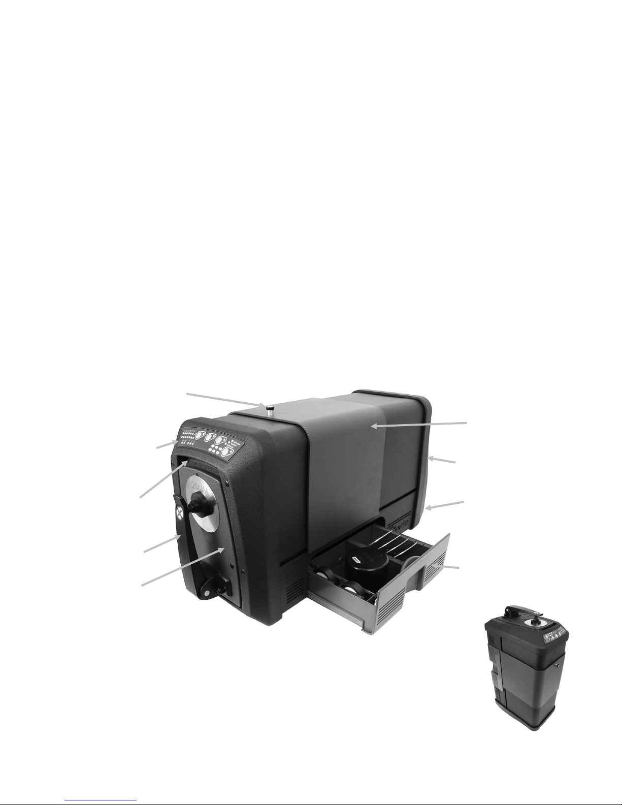
Sample holder
Button and indicator
membrane label (refer to
for a
Transmission
Accessory drawer (white tile,
green tile, black trap, aperture
plates, UV cal plaque)
Ci7XX0 instrument can
Communication,
Front lifting grip
Rear lifting grip
Locking pin
Sample door
OVERVIEW
The Ci7XX0 is a reflectance / transmittance sphere benchtop spectrophotometer offering
agreement with these X-Rite/GretagMacbeth instruments: 7000A, Color i7, and Color i5. The
Ci7XX0 Spectrophotometer includes these features:
• Multiple areas of sample view in both reflectance and transmittance.
• Self-adjusting, dual zoom lens to manage the measurement area and eliminate
configuration errors between aperture plates and lens position.
• External video monitor viewing, preview video in the software application, and hinged
sample door preview for measurement accuracy and targeting purposes.
• Haze measurement mode (excludes Ci7500 series).
• Automated ultra violet (UV) adjustment for measuring fluorescent or optically brightened
samples.
• USB interface to PC and software applications.
• Indicator panel display with dual buttons for standard and sample measurements, and
warning indicators for calibration interval.
• Dampened sample arm holder that prevents sample damage.
• Embedded white sample holder ceramic. Ideal for reflectance measurements that require a
white backing, such as textiles, plastics or other less than opaque samples (Standard on
Ci7800/Ci7860 instrument and optional on the other models).
• Supports embedded NetProfiler.
access cover
Front Panel
description)
line cord and
power switch
also operate in the upright
position with optional kit.
9
Page 12

Ci7XX0 BENCHTOP SPECTROPHOTOMETER
Packaging Information
If you are reading this documentation, you have already followed the instructions detailed in the
Ci7XX0 installation sheet that was included in the shipping carton. Please keep the installation
sheet for reference. Keep your shipping carton in case you need to return your instrument to the
factory for service.
Your instrument packaging should contain all the items listed below. If any of these items are
missing or damaged, contact X-Rite or your Authorized Representative.
• Software box containing the Ci7XX0 Driver and Documentation CD along with any other
optional software you may have ordered such as Color iControl and NetProfiler.
• Ci7500 Series, Ci7600 Series, or Ci7800 Series Spectrophotometer
• Certificate of performance
• Installation instructions sheet
• USB cable
• AC power cord
• Sample shelf with thumb screws
• Transmission kit (optional on Ci7800 Series & Ci7600 Series)
The following accessories are stored in the instrument accessory drawer.
• Round white calibration tile
• Round green performance tile
• Black trap for calibration
• Ci7800 Series aperture plates: 25 mm, 17 mm, 10 mm, 6 mm, (3.5 mm optional)
Ci7600 Series aperture plates: 25 mm, 10 mm, 6 mm, (3.5 mm optional), (17 mm
optional)
Ci7500 Series aperture plates: 25 mm, 10 mm
• White UV plaque
Instrument Setup
Please follow the instructions detailed in the Ci7XX0 Installation Instructions sheet found as the
first item in your shipping box when you opened it. A PDF file of the Installation Instructions also
can be found on the Ci7XX0 Driver and Documentation CD.
Powering the Instrument
The power on-off AC switch is located on the back of the instrument. Press the top of the rocker
switch to turn on the instrument and wait 50 seconds for the instrument to boot up. If the
instrument does not power up after approximately 50 seconds, check the power connections to
the unit and main power availability (breakers, fuses). If these connections are fine, check the
instrument’s fuse. Refer to “Fuse Replacement” in the Appendix.
A power “standby” button is located on the front panel of the instrument. This button is used to
power down the instrument into a low power state, or wake the instrument after it goes into a
power down state. A power on condition is designated by a solid green light indicator. Simply
press the power “standby” button to wake or power down the instrument into “standby” mode.
Discontinue use if AC cord is damaged.
Ensure AC cord ratings meet or exceed the instrument ratings (see Specifications section in
the Appendices).
10
Page 13
Ci7 XX0 BENCHTOP S P ECTROPHOTOMETER
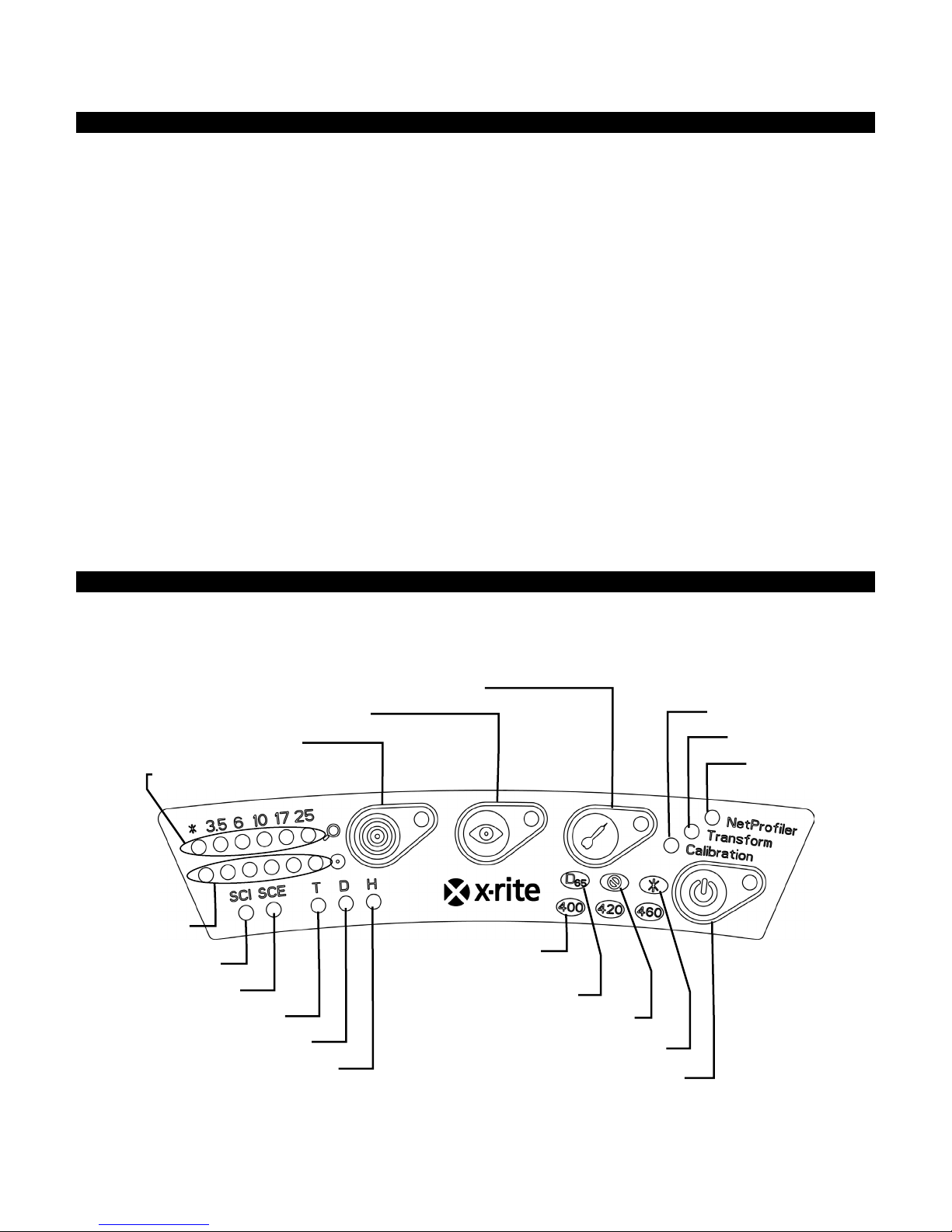
Specular Included
Specular Excluded
Lens
Standard button and indicator
Preview button and indicator
Trial button and indicator
Calibration
Transform
NetProfiler
Total Transmission
Direct Transmission
Haze
D65 Illuminate
UV Excluded
400, 420, 460 nm
cut filters
Custom UV (user defined)
Power “standby” button and indicator
Aperture plate
Sample Preview Method
The instrument has three sample preview methods:
Sample Door
This method enables you to open the sample door and look at the sample position in the viewport.
You can make manual adjustments if necessary to obtain optimum sample alignment. Refer to the
instructions on using the Sample Door Preview Method.
External Video Monitor Feature
This method requires an external preview video monitor. The monitor is plugged into the video
connector located on the back of the instrument. After the monitor is connected, the Preview
button on the spectrophotometer can be pushed to turn live preview video on and off. Video
on/off is the default functionality of the Preview button when using a reflectance measurement
mode. However, your software application may assign a different behavior to the button for
various reasons.
Live Preview Video in PC Software Application
This method requires a software application, such as Color iQC to provide a means to view video
within the application. Follow the instructions in your application to preview video for sample
alignment.
Note: DO NOT power down the instrument into “Standby” mode when preview video is actively
streaming in the application. Doing so may result in an unstable operation condition.
Front Panel
The front panel is used to initiate measurements and also indicate a variety of instrument
conditions, such as calibration status, measurement status, etc. Below is description for each
indicator and button.
11
Page 14

Ci7XX0 BENCHTOP SPECTROPHOTOMETER
Lens and Aperture Plate Indicators (*, 3.5, 6, 10, 17, 25)
• The top row of LEDs illuminates to indicate the current lens position. The “*” illuminates
when the lens is in a custom position. The LED will light red if the unit is configured with a
lens position larger than the installed aperture plate size.
• The bottom row of LEDs illuminates to indicate the currently installed aperture plate. The
“*” illuminates for custom plates and transmission aperture plates (with white reflective
ring), and blinks if the instrument could not detect the installed plate. If auto is enabled
for the lens, then the installation of an aperture plate automatically sets the lens to match
the aperture plate.
Standard Button and Indicator
• The standard button is used to initiate a standard measurement. Note: The button must
be supported by your application software and function as programmed.
• The indicator illuminates green when programmed to perform a measurement. It may
also be programmed to flash green to support features in your application.
Preview Button and Indicator
• The preview button is used in conjunction with the external video monitor preview
feature.
• The indicator illuminates green when it is activated.
• The video preview is toggled when a reflectance measurement mode is selected. When a
transmission measurement mode is selected, the button will toggle the green
transmission targeting laser on and off.
• The behavior of the button may also be programmed in your software application.
Trial Button and Indicator
• The trial button is used to initiate a trial measurement. Note: The button must be
supported by your software application and function as programmed.
• The indicator illuminates green when programmed to perform a measurement. It may
also be programmed to flash green to support features in your application.
NetProfiler
• Indicator Off: NetProfiler feature is not enabled.
• Solid Green: NetProfiler subscription is currently activated.
• Solid Amber: The profile has expired and updating is recommended.
Calibration
• Solid Red: Calibration is required
• Solid Green: White, black, and UV calibration are not required at this time
• Solid Amber: White and black calibration are not needed, but UV calibration has expired.
Measurements can still be taken in this condition. It is up to the user to decide if the UV
calibration should be updated at this time.
Transform
• Indicator Off: Transform feature in not enabled
• Solid Green: Transform feature is activated
Specular Included (SCI)
• Illuminates when a specular included measurement is selected.
12
Page 15

Ci7 XX0 BENCHTOP S P ECTROPHOTOMETER
Specular Excluded (SCE)
• Illuminates when a specular excluded measurement is selected.
Total (T) – excludes Ci7500 series
• Illuminates when a total transmission measurement is selected.
Direct (D) - excludes Ci7500 series
• Illuminates when a direct transmission measurement is selected.
Haze (H) - excludes Ci7500 series
• Illuminates when a haze measurement is selected.
D65 Illuminate
• Illuminates when it is UV calibrated to a D65 UV illumination condition.
UV Excluded (
• Illuminated when one of the UV filters fully blocks the UV component in the lamp to fully
exclude UV illumination.
Custom (
• Illuminated when a user-defined D65 or other UV condition is selected.
400
• The 400 nm UV cutoff filter is in use. This filter is adjustable and can be used to calibrate
420 - excludes Ci7500 series
• The 420 nm UV cutoff filter is in use. This optional filter is adjustable and can be used to
460 - excludes Ci7500 series
• The 460 nm UV cutoff filter is in use. This optional filter is not adjustable and can only be
Power “standby” button and indicator
• Refer to Powering the Instrument earlier in this section.
*
UV conditions.
calibrate UV conditions.
set to fully exclude UV illumination.
)
)
13
Page 16
Ci7XX0 BENCHTOP SPECTROPHOTOMETER
Screw holes
Thumbscrew
Sample shelf
Thumbscrew
Sample Shelf
A sample shelf is provided to help align a sample with the measurement port. It is also useful for
providing consistent sample placement when multiple samples require a measurement at the
same location.
To install the sample shelf, position the shelf’s elongated slots over the two holes in the sample
door and attach it with the thumb screws provided.
Adjust the shelf by loosening the thumbscrews and sliding the shelf up or down.
Sample Holder
The sample holder can be locked in a down position. This is convenient when large samples are
measured, or when the aperture plate is changed or the sample holder is removed.
Simply open the sample holder to its maximum position to lock into position.
14
Page 17
Ci7 XX0 BENCHTOP S P ECTROPHOTOMETER
Pull from top
Sample door
Observe sample
here through
viewport opening
Sample holder
Sample Door
The sample door can be opened for a completely unobstructed view of the sample presented at
the view port. When completely open, the sample door allows you to adjust the sample at the
view port for optimal placement.
To use the sample door:
1. Open the sample holder by pulling it towards you. Place your sample at the view port and
close the sample holder.
2. Open the door from the top by using your fingers, and gently lower the door to the complete
open position. See the figure below.
3. With the sample door completely open, view the sample at the view port and make sure the
sample is in an optimal position for measuring.
4. Close the sample door and prepare for the measurement.
Specular Control
You can change the specular component setting on the spectrophotometer for reflectance
measurements using your software application. Select the desired specular component
measurement mode; Included (SCI), Excluded (SCE), or Dual Mode (SCE/SCI). The indicator for
15
Page 18

Ci7XX0 BENCHTOP SPECTROPHOTOMETER
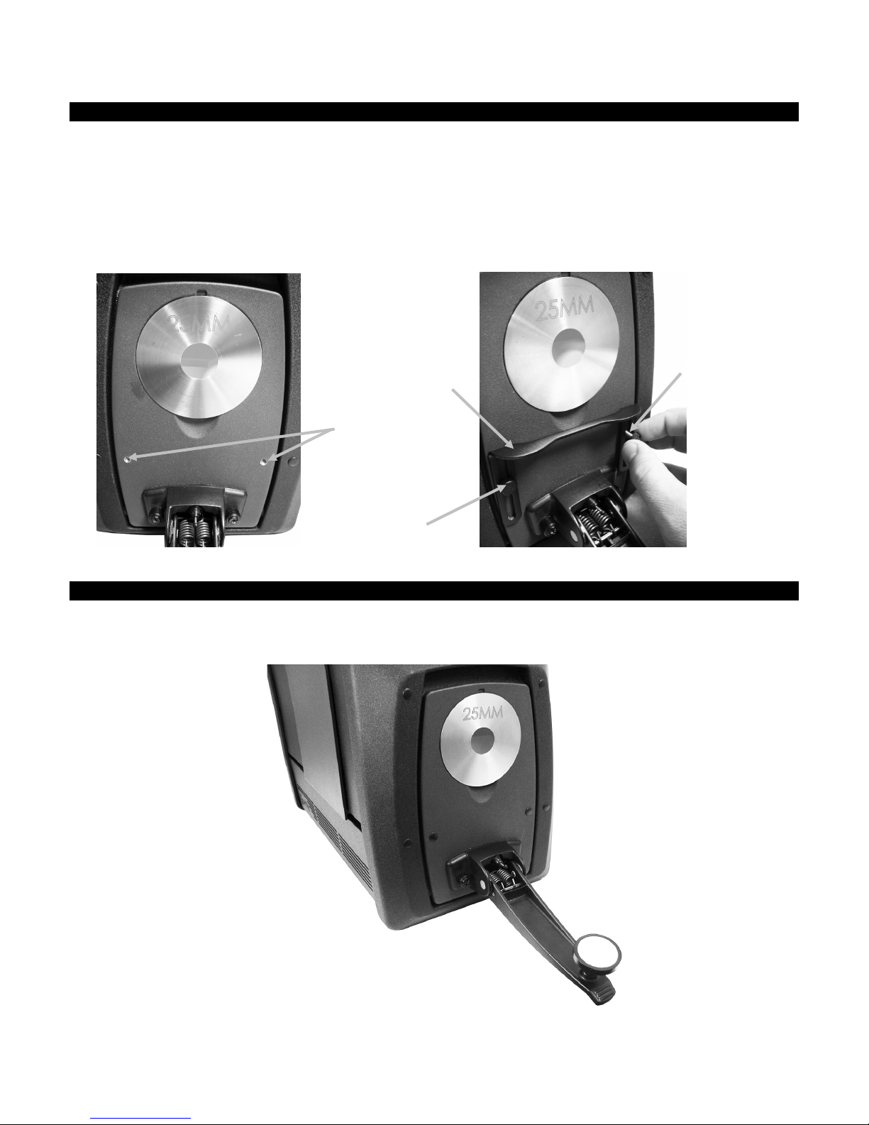
Aperture plate
Notch below plate
either setting (or both if you have dual mode) on the front panel becomes illuminated based on
your selection. The instrument simultaneously measures specular included and specular excluded
for all reflectance measurements. Your software application should decide which measurement
data to request from the spectrophotometer according to the user requirements.
UV Control
Your spectrophotometer is equipped with an automated 400nm UV filter. This can be set to fully
exclude the UV portion of the light source in the spectrophotometer or can be used to calibrate and
adjust the UV level, for instance to match the UV component of D65 daylight. The instrument
supports built-in UV calibration positions for UV included, UV excluded, and D65. The instrument
also supports an unlimited number of user-defined UV positions which are set up, calibrated, and
managed using the PC software application. A UV calibration plaque is provided in the accessory
drawer that has been calibrated in the factory with a CIE whiteness value for true D65. Your system
includes a 400 nm UV filter, and may optionally include a 420 and/or 460 nm UV filter as well.
Aperture Control
By default, the spectrophotometer is configured to auto-recognize an aperture plate when
installed at the measurement port, and to auto-drive the lens to the matching size. The lens
position is also dependant on the measurement mode. If for example the instrument is configured
with the 10 mm aperture plate in a reflectance measurement mode and the user switches to a
transmission measurement mode, the instrument auto-drives the lens to create the measurement
size at the transmission measurement location.
Note: The automatic lens behavior can be overridden by the user in software if desired. If you prefer to
not have matching aperture and lens settings (to have an over illumination setup), you can use your
software application to configure the instrument. Keep in mind that a valid measurement size is less than
or equal to the aperture plate size. If the lens position and the installed aperture plate do not match, the
lens LED will illuminate red to indicate this discrepancy. Auto recognition is applicable to Reflectance
mode only.
To install an aperture plate on the instrument:
1. Open the sample holder to the fully open position.
2. Using your fingers, remove the aperture by lifting outward from the notch below the existing
aperture plate.
16
Page 19

Ci7 XX0 BENCHTOP S P ECTROPHOTOMETER
3. Locate the plate to be installed in the accessory drawer and fit the aperture over the rim on
the sample door. The plate is held in place by magnets.
4. Gently close the sample holder.
5. The aperture plate will be automatically recognized when the door is closed, and activate the
auto-zoom lens if set to the auto mode. Auto recognition is only valid for Reflectance mode
aperture plates. For transmission aperture plates, the asterisk LED lights up green.
17
Page 20

Ci7XX0 BENCHTOP SPECTROPHOTOMETER
White
tile
CALIBRATING
The spectrophotometer should be calibrated every eight hours of operation.
Each spectrophotometer configuration that is used should be calibrated. A configuration consists
of the following components:
• Measurement mode: Transmission, Reflectance, R/T, or Haze
• Aperture size (3.5 mm, 6 mm, 10 mm, 17 mm, or 25 mm)
• Lens position
• Specular included or excluded condition (SCI or SCE)
• UV included, D65 calibration or excluded condition
Calibration Notes
• Dirt or dust in the optics area will cause an inaccurate calibration reading. Refer to
the Appendices for optics cleaning procedure.
• The white calibration tile is dramatically affected by smudge marks, dust, and
finger prints. Refer to Appendices for calibration tile cleaning procedures.
• The black trap should be cleaned periodically to remove any dust or
contamination. Refer to Appendices for black trap cleaning procedures.
Reflectance Calibration Procedure
To calibrate your spectrophotometer in reflectance measurement mode you need to use your
software application. Follow these steps:
1. Verify the 25 mm aperture plate is installed.
2. Launch the calibration procedure from the software application.
3. Remove the white calibration tile from the accessory drawer. Pull down on the sample holder
and position the tile on the sample holder clamp. Make sure the white ceramic side is facing
the aperture plate.
4. While holding the tile in place, close the sample holder to the aperture plate.
calibration
5. Initiate the calibration tile measurement from the software. After the measurement, remove
the calibration tile and return it to the accessory drawer.
18
Page 21

Ci7 XX0 BENCHTOP S P ECTROPHOTOMETER
Align
Green
6. Remove the black trap from the accessory drawer and position it on the aperture plate. Make
sure to align the tab at the top edge of the trap with the notch at the top of the aperture
plate.
7. Initiate the black trap measurement from the software.
8. Remove the black trap and return it to the accessory drawer.
9. Once the calibration process is complete, the calibration indicator becomes lit. Any change to
the spectrophotometer configuration may result in the calibration indicator changing from
green (calibrated) to red (not calibrated).
10. Continue with additional configuration calibrations as required.
Green Tile Color Check (optional)
1. Perform a calibration procedure if you have not already done so. Refer to the Calibrating section.
2. Remove the green tile from the accessory drawer. Pull down on the sample holder and
position the tile on the sample holder clamp. Make sure the green ceramic side is facing the
aperture plate.
3. While holding the tile in place, close the sample holder to the aperture plate.
calibration tile
4. Initiate the green tile check procedure from the software application. After the measurement,
remove the green tile and return it to the accessory drawer.
Note: Tile values are generated at a temperature of 22°C. Refer to the software application for
additional information.
19
Page 22

Ci7XX0 BENCHTOP SPECTROPHOTOMETER
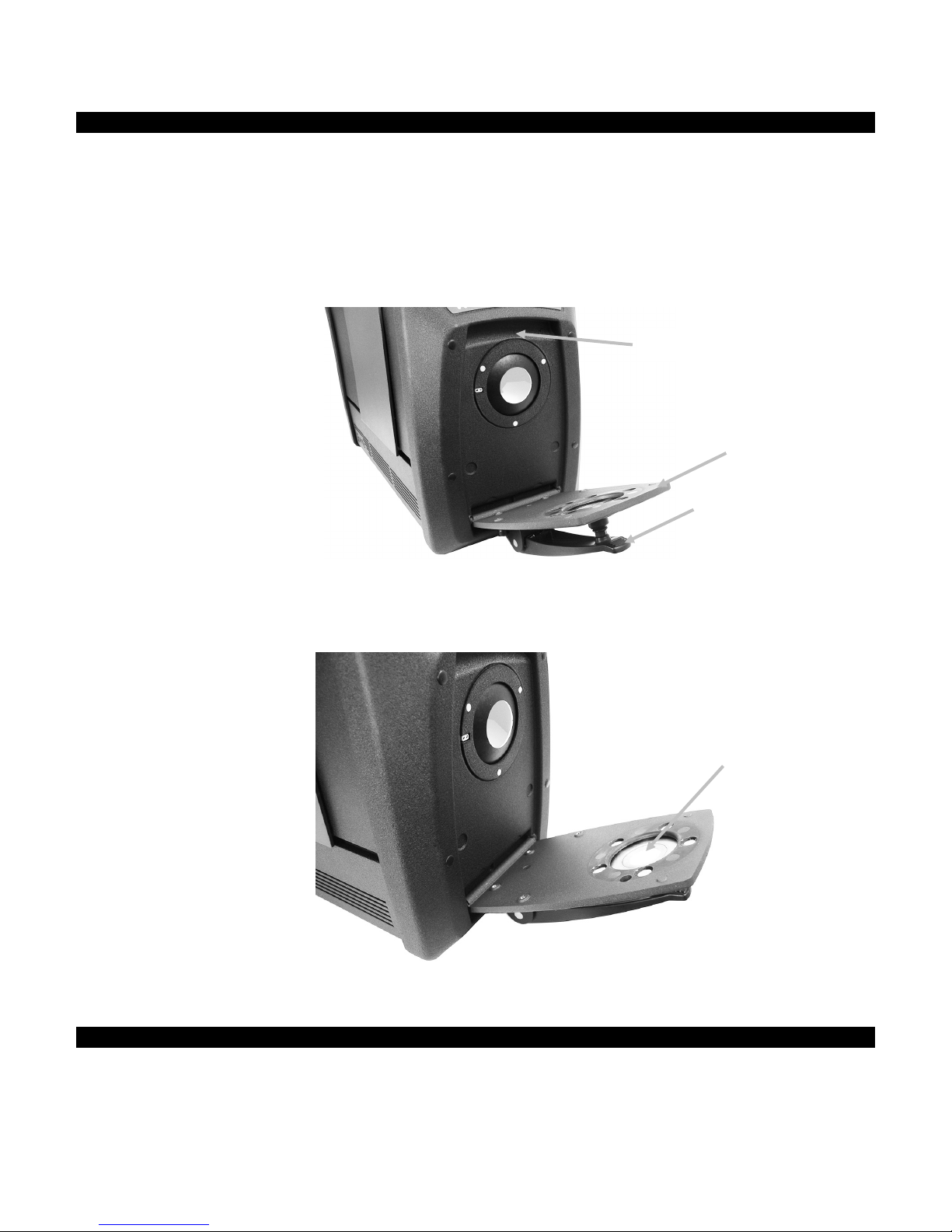
Aperture plate
Transmission
Transmission Calibration Procedure (excludes Ci7500 series)
To calibrate your spectrophotometer in transmission measurement mode, you need to first locate
the following items in your optional transmission kit:
Aperture plates 6 mm, 10 mm, 17
mm, or 25 mm (with white
reflective ring). The plate can be
used for both transmission and
reflection measurements in the R/T
and haze modes.
Transmission sample holder
Transmission white plaque
Black plastic blocking panel
Note: NEVER use the black trap for black calibration when performing Transmission calibration.
Transmission Calibration Setup
Note: For R/T (Reflection/ Total Transmission), perform a Reflectance Calibration before
continuing.
1. Using your software application, launch the calibration process from the software interface.
2. Mount the 25 mm aperture plate (with white reflective ring) to the measurement port at the
front of the instrument.
3. Position the transmission white plaque on the sample holder.
plaque
4. Follow any prompts from the software regarding the white calibration.
5. Open the transmission cover by lifting up on the locking pin while sliding the cover to the back.
20
Page 23

Ci7 XX0 BENCHTOP S P ECTROPHOTOMETER
Black plastic
Carriage base
Total transmission
6. Refer to the remaining Total, Direct, or R/T Calibration procedures that follow.
Total Calibration
1. Place the sample transmission holder base inside the transmission compartment.
calibration shown
2. Attach the appropriate clamp and stop to the base with the thumb screws.
3. Center the black plastic blocking panel in the transmission sample holder and place between
the stop and clamp toward the sphere.
blocking panel
4. Close the cover and continue with calibration.
21
Page 24

Ci7XX0 BENCHTOP SPECTROPHOTOMETER
Black plastic
Carriage base
Direct transmission
5. Once the calibration process is complete, the calibration LED becomes lit. Any change to the
spectrophotometer configuration may result in the calibration LED turning from green
(calibrated) to red (not calibrated). Remember that each configuration needs to be calibrated.
Direct Calibration
1. Place the sample transmission holder base inside the transmission compartment.
calibration shown
2. Attach the appropriate clamp and stop to the carriage base with the thumb screws.
3. Center the black plastic blocking panel in the transmission sample holder and position toward
the lens side.
blocking panel
4. Close the cover and continue with calibration.
22
Page 25

Ci7 XX0 BENCHTOP S P ECTROPHOTOMETER
Black plastic
Carriage base
R/T calibration shown
5. Once the calibration process is complete, the calibration LED becomes lit. Any change to the
spectrophotometer configuration may result in the calibration LED turning from green
(calibrated) to red (not calibrated). Remember that each configuration needs to be calibrated.
R/T Calibration
1. Place the sample transmission holder base inside the transmission compartment.
2. Attach the appropriate clamp and stop to the carriage base with the thumb screws.
3. Center the black plastic blocking panel in the transmission sample holder and position toward
the sphere.
blocking panel
4. Close the cover and continue with calibration.
5. Once the calibration process is complete, the calibration LED becomes lit. Any change to the
spectrophotometer configuration may result in the calibration LED turning from green
(calibrated) to red (not calibrated). Remember that each configuration needs to be calibrated.
Note: The green LED will never appear for any Calibration Mode configured to include a UV Cal
option. UV cannot be calibrated in this mode.
23
Page 26

Ci7XX0 BENCHTOP SPECTROPHOTOMETER
UV calibration
plaque
UV Calibration Procedure
Note: UV Calibration requires the configured reflectance aperture plate to be installed.
1. Perform a white and black calibration as previously explained.
2. Initiate the UV calibration procedure from the software application.
3. Enter the calibration whiteness value in the appropriate field.
4. Remove the UV calibration plaque from the protective bag in the accessory drawer.
5. Pull down on the sample holder and position the UV calibration plaque against the 25 mm
aperture plate. Make sure the white surface is facing the aperture plate.
6. Close the sample holder clamp to the UV calibration plaque.
7. Initiate the UV calibration measurement from the software.
8. Follow the procedure in the application.
9. Remove the UV calibration plaque, place in protective bag and return it to the accessory
drawer.
10. If required, repeat the normal white and black calibration procedure as before.
24
Page 27

Ci7 XX0 BENCHTOP S P ECTROPHOTOMETER
Sample
Hole plug
Hole plug
Hole plug
Hole plug
MEASURING
You should refer to the documentation or online help for the software application that you are
using with your instrument. All applications that use the instrument must be running during
measurements.
Reflectance Measurements
To take a measurement using your spectrophotometer, follow these steps to ensure an accurate
reading.
1. Ensure the desired aperture plate is installed.
2. Edit the current configuration or load appropriate configuration from the application.
3. Calibrate for the current configuration if needed.
4. Prepare your sample for measurement.
5. Open the sample holder on the spectrophotometer to the fully open position. Position the
sample at the view port and slowly close the sample holder. The sample holder is dampened
to prevent the holder from closing with too much force and possibly damaging the sample.
6. Use the computer screen or the drop down door to view the sample and adjust the sample
measurement targeting area.
Caution: Do not look directly into the measurement optics when the instrument is on.
7. Trigger the measurement using one of the following methods:
a. Select "Measure Standard" or "Measure Trial" from your software. Follow the software
instructions for loading the sample at the view port.
OR
b. Press the Standard or Trial button on the instrument front panel.
8. The measurement is taken. The data is displayed in your application. Follow the instructions
for saving the data in the software.
Note:
When measuring large or oddly-shaped samples you can open the sample holder completely or
remove the sample holder if necessary. The sample is then held securely against the view port.
It is also recommended that you remove the four outer hole plugs from the front of the
instrument to ensure that large samples remain flat during measurements.
When holding a sample for measurement yourself, remember to keep the sample perfectly
still. Also, the sample surface should be able to rest completely flat against the aperture plate,
preventing any light from entering the view port.
25
Page 28

Ci7XX0 BENCHTOP SPECTROPHOTOMETER
Sample stop for 6 mm, 10
.
Sample clamp
Carriage base
Clamp thumb screws (2)
Stop thumb screw (2)
Carriage base thumb screw
Base plate
Transmission Measurements (excludes Ci7500 series)
A transmission indicator illuminates on the front panel based on your selection in the software.
The transmission sample holder is designed to mount inside the transmission compartment. It is
used to measure thin films at both the sphere (total transmission) and at the lens (direct
transmission). Direct transmission is 25 mm measurements only. Each transmission kit contains:
four sample stops and clamps, four aperture plates with white reflective ring, one transmission
white plaque, one black plastic blocking panel, and one cuvette sample holder. Choose the sample
stop and clamp appropriate for your application.
Before taking a transmission measurement, make sure the instrument is calibrated for the
measurement mode and set the instrument to transmission mode using your application.
Measurement Notes:
• Liquids are measured using the cuvette sample holder
• Always make certain that the sample is flush and parallel to the opening in the sphere or
the lens
• If transmission white plaque gets soiled, it must be replaced
• Close the cover when measuring
• Use aperture plates with white reflective ring
• Use the transmission white plaque, not smooth glossy calibration tile
Transmission Sample Holder Description
mm, 17 mm and 25 mm
Total Transmission Measurement
Total measurements are taken with the sample positioned between the stop and clamp toward the
sphere. Total Transmission is appropriate for measuring translucent samples which exhibit some
scattering of the light. A total transmission measurement will make certain that all transmitted
light is measured for an accurate reading.
1. Mount the appropriate aperture plate (with white reflective ring) to the measurement port at
the front of the instrument.
2. Position the transmission white plaque on the sample holder as previously explained in the
calibration section.
26
Page 29

Ci7 XX0 BENCHTOP S P ECTROPHOTOMETER
Lens Side
Sphere Side
Clamp mounting holes
Base plate in total
position
3. Open the transmission cover by lifting up on the locking pin while sliding the cover to the
back.
4. Align the sample holder base plate pins to the base plate mounting channel holes inside the
transmission area.
Position the base plate with the clamp mounting holes on the sphere side. Be careful to get
the angle correct. Care should be taken to properly align the base plate so that the sample is
positioned between the stop and clamp toward the sphere.
transmission
5. Attach the appropriate sample stop to the base plate and clamp to the carriage base with the
thumb screws. We recommend using a stop plate with all sizes including 25 mm.
The sample is held in position using a sample stop on the sphere side of the sample, and a
spring loaded clamp on the side of the sample away from the sphere.
Care should be taken to properly align this holder so that the stop plate is positioned flush
and tight against the opening in the sphere. Do not tighten the thumb screws until the
sample has been positioned tight against this opening.
27
Page 30

Ci7XX0 BENCHTOP SPECTROPHOTOMETER
Transmission holder with sample at the sphere (total measurement) for 25
6. Pull the clamp back and position the sample between the clamp and stop. You may want to
temporarily tighten the carriage base thumb screw to hold the clamp in place while
positioning the sample. Slowly release the sample clamp/carriage base to secure the sample.
mm, 17 mm, 10 mm, and 6 mm, measurements
7. Once properly position, tighten the thumb screws and close the transmission cover.
8. Initiate the measurement by selecting “Measure Standard" or "Measure Trial" from your
software application, or press the Standard or Trial button on the front panel.
9. The measurement is taken. The data is displayed in your application.
10. Follow the instructions for saving the data in the application.
Direct Transmission Measurement
Direct measurements are taken with the sample positioned towards the lens in the back of the
instrument. Direct Transmission is appropriate for measuring transparent samples which exhibit
no scattering of the light. This would generally be samples colored with dyes rather than
pigments. When measuring with this method the diffuse light is collimated, this means that the
light rays are travelling in a parallel fashion as they pass through the sample.
Note: When performing Direct Transmission measurements, only the 25mm clamp, stop, and
aperture plate (with white reflective ring) should be used.
1. Mount the 25 mm aperture plate (with white reflective ring) to the measurement port at the
front of the instrument.
2. Position the transmission white plaque on the sample holder as previously explained in the
calibration section.
3. Open the transmission cover by lifting up on the locking pin while sliding the cover to the
back.
28
Page 31

Ci7 XX0 BENCHTOP S P ECTROPHOTOMETER
Lens Side
Sphere Side
Clamp mounting holes
Base plate in direct
4. Align the sample holder base plate pins to the base plate mounting channel holes inside the
transmission area.
Position the base plate with the clamp mounting holes on the lens side. Be careful to get the
angle correct. Care should be taken to properly align this base plate so that the sample is
positioned towards the lens. It does not sit flush against the lens. Verify the angle is correct
by looking through the front aperture plate.
5. Attach the 25 mm sample stop to the base plate and 25 mm clamp to the carriage base with
the thumb screws.
The sample is held in position using a sample stop on the lens side of the sample, and a
spring loaded clamp on the side of the sample away from the lens.
Do not tighten the thumb screws until the sample has been positioned tight against this
opening.
6. Pull the clamp back and position the sample between the clamp and stop. You may want to
temporarily tighten the carriage base thumb screw to hold the clamp in place while
positioning the sample. Slowly release the sample clamp/carriage base to secure the sample.
transmission position
29
Page 32

Ci7XX0 BENCHTOP SPECTROPHOTOMETER
Transmission holder
with sample at the lens
(direct measurement)
for 25 mm
measurements
7. Once properly position, tighten the thumb screws and close the transmission cover.
8. Initiate the measurement by selecting “Measure Standard" or "Measure Trial" from your
software application, or press the Standard or Trial button on the front panel.
9. The measurement is taken. The data is displayed in your application.
10. Follow the instructions for saving the data in the application.
R/T (Reflection/Total Transmission) Measurement
R/T measurements provide the ability to compensate for light lost through the sample (as opposed
to light absorbed). When using R/T mode for plastic formulation the formulation software will
attempt to match opacity of the standard as well as color.
Two measurements are taken to create this value. One measurement is taken with the sample
positioned at the reflection port (reflection measurement). The second measurement is taken with
the sample positioned flush against the stop at the back of the sphere (total transmission
measurement). When measuring with this method the diffuse light travels through the object from
all angles. Again the sample is illuminated from all possible angles with a diffuse light source.
1. Mount the aperture plate (with white reflective ring) to the measurement port at the front of
the instrument.
2. Position the transmission white plaque on the sample holder as previously explained in the
calibration section.
3. Position the sample at the reflection port as previously explained in the Reflectance
Measurement section.
4. Initiate the measurement by selecting “Measure Standard" or "Measure Trial" from your
software application, or press the Standard or Trial button on the front panel. The
measurement is taken.
5. Open the transmission cover by lifting up on the locking pin while sliding the cover to the back.
30
Page 33

Ci7 XX0 BENCHTOP S P ECTROPHOTOMETER
6. When taking the transmission measurement the sample is held in position using the
transmission holder with a stop plate on the sphere side of the sample, and a spring loaded
clamping plate on the side of the sample away from the sphere.
7. Attach the appropriate sample stop to the base plate and clamp to the carriage base with the
thumb screws. We recommend using a stop plate with all sizes including 25 mm.
8. Remove the sample from the sample holder. Care should be taken to properly align the base
plate so that the sample is positioned between the stop and clamp toward the sphere. When
setting up for measurements, do not tighten the thumb screws until the sample has been
positioned properly.
9. Once properly position, tighten the thumb screws and close the transmission cover.
10. Initiate the measurement by selecting “Measure Standard" or "Measure Trial" from your
software application, or press the Standard or Trial button on the front panel. The
measurement is taken.
11. Follow the instructions for saving the data in the application.
31
Page 34

Ci7XX0 BENCHTOP SPECTROPHOTOMETER
R/T correlation - Ci7XX0 to Ci7000A
Testing has shown that to achieve the best correlation between a Ci7XX0 to a Ci7000A the
following combinations of transmission port, stops, and aperture plates should be used:
• 25mm transmission port, with 25 mm stop and 25 mm aperture plate with white reflective
ring
or
• 17mm transmission port, with 17 mm stop and 17 mm aperture plate with white reflective
ring
Liquid Measurements
Measurement and Calibration Notes
• Liquids should be measured using the total transmission technique, never use direct
transmission for liquids
• Be very careful with placement of the cuvette, make certain it is positioned square and
flush to the sphere opening
• Make sure the cuvette’s position is centered over the opening in the sphere
• Perform white calibration with cuvette and clear liquid in the sample holder
• The clear liquid should be the base of whatever material you are working with
• When performing black calibration the blocker should be positioned between the cuvette
and the opening in the sphere
Cuvette Cleaning and Handling
• Care should be taken to ensure the cuvette and holder is kept clean. Carefully wash the
holder and cuvette in warm, soapy water and rinse thoroughly.
• Never touch the cuvette windows with your fingers as the oils in your skin will etch the
windows. Handle the cuvette by the edges.
• Always leave an air gap between the bottom of the lid and the top of the liquid sample.
The force of pressing the lid against the liquid sample can cause the windows to be
weakened and crack.
• Extreme care should be taken to prevent the sample liquid from being spilled into the
transmittance chamber. NEVER FILL THE CELL WHILE IT IS IN THE TRANSMISSION
COMPARTMENT.
Procedure:
1. Loosely attached the cell stand assembly to the carriage base with two thumb screws. A
clamp is not required for this measurement.
2. Slide the cell stand forward and tighten the thumb screws.
3. Make sure the cuvette is clean (see Cleaning and Handling). Carefully fill the cuvette with
the sample liquid until the liquid is approximately 8 mm from the top. If any liquid spills
on the sides of the cuvette, wipe it off with a clean cloth.
4. Insert the cuvette into the cell stand.
32
Page 35

Ci7 XX0 BENCHTOP S P ECTROPHOTOMETER
Cuvette in the cell stand (total
measurement)
5. Initiate the measurement by selecting “Measure Standard" or "Measure Trial" from your
software application, or press the Standard or Trial button on the front panel.
6. The measurement is taken. The data is displayed in your software application.
7. Follow the instructions for saving the data in the software.
Haze Measurements
Measurement and Calibration Notes
• To obtain a true haze measurement requires a haze meter (ASTM D1003). It is possible,
however, to use a sphere geometry spectrophotometer capable of transmission
measurements to obtain an index, known as correlated haze, with good correlation to a
haze meter.
• The sample to be measured is placed against the sphere.
• To calibrate use the 25 mm aperture plate (with white reflective ring), transmission white
plaque and black trap positioned at the reflectance port.
• Before you can take a Haze measurement you need to calibrate for the haze
measurement first, unless you are already in Haze Measurement mode using a current
haze calibration.
Procedure:
1. Mount the 25 mm aperture plate with the white ring at the measurement port as previously
explained.
2. Select “Haze” as the measurement type within your software.
3. A haze calibration is automatically launched. Follow the prompts from the software regarding
calibration.
4. Once the haze calibration is complete you can begin to take haze measurements.
5. Load your sample in the transmission sample holder at the sphere within the transmission
compartment.
6. Select “Measure Standard”, “Measure Trial”, or press the appropriate measure button on the
instrument.
7. If you later change the measurement mode to another measurement type than Haze you
may be prompted to calibrate the instrument.
33
Page 36

Ci7XX0 BENCHTOP SPECTROPHOTOMETER
APPENDICES
Service Information
X-Rite provides repair service to their customers. Because of the complexity of the circuitry, all
warranty and non warranty repairs should be referred to an authorized service center. For non
warranty repairs, the customer shall pay shipping and repair cost to the authorized service
center, and the instrument shall be submitted in the original carton, as a complete unaltered unit,
along with all the supplied accessories.
X-Rite, Incorporated has offices around the world. You can contact us using one of the following
methods:
• To identify the X-Rite service center nearest you, please visit our web site at:
www.xrite.com and click the Contact Us link.
• For online help, visit our web site (www.xrite.com) and click the Support link. Here you
can search for software or firmware updates, white papers, or frequently asked questions
which can quickly resolve many common user problems.
• Send an e-mail to Technical Support detailing your problem and listing your contact
information. For the Americas email CASupport@xrite.com, for Europe email
EMEAtechsupport@xrite.com, for Asia email TechSupportAsiaDist@xrite.com.
• For sales questions or to order cables and accessories, visit our web site (www.xrite.com)
or contact your nearest X-Rite dealer or service center.
• Problems and questions can also be faxed or emailed to your local X-Rite office listed on
our website.
34
Page 37

Ci7 XX0 BENCHTOP S P ECTROPHOTOMETER
Cleaning Requirement
Clean,
Mild
Lint-
Personal
Exterior
Transmission
Black Plastic
Sphere
Aperture
Transmission
Black Trap
UV Calibration
Cleaning the Instrument
Your instrument requires very little maintenance to achieve years of reliable operation. However,
to protect your investment and maintain reading accuracy, a few simple-cleaning procedures
should be performed from time to time.
IMPORTANT:
Remove AC power from the instrument before performing any of these
cleaning procedures.
CAUTION: DO NOT use any solvents to the clean the instrument.
CAUTION: Use proper personal protective equipment (e.g., safety glasses)
when using compressed air.
If can air is used for any of the cleaning procedures that recommend air, do not
invert or tilt the can during use. This could cause damage.
CAUTION: When using chemicals, always follow the manufacturer’s personal
protection equipment recommendations in the chemical SDS.
Cleaning Quick Reference Table
Below is a quick reference to help you determine the proper cleaning methods. Refer to the
following pages for a more detailed description of the individual cleaning procedures.
Compartment
Blocking
Panel
Plates
White Plaque
Plaque
Compressed
Air
Cleaner
with Water
free
Cloth
Protection
Equipment
(per SDS)
35
Page 38

Ci7XX0 BENCHTOP SPECTROPHOTOMETER
General Exterior Cleaning
The case, front panel, sample holder and surface of your instrument should be kept clean and
free of dust. This can be accomplished by dusting these components with a lint-free cloth.
General cleaning should be performed on a weekly basis or more often if the unit is used in a
dusty operating environment.
Cleaning the Transmission Compartment
Use clean, dry compressed air to blow any dust, dirt or other contamination out of the
transmission compartment.
Cleaning the Calibration Tiles
Ceramic standards (calibration tiles) are widely used in color science as standards of reflectance
factor. Their principal virtue is the stability of their reflection properties. If they are to serve their
intended purpose, it is necessary that the surfaces of these tiles be maintained in a stable
condition. The cleaning of any precision optic risks degrading the surface. Therefore, the need for
cleaning should be minimized by returning the tile to its storage case or covering it with a
protective bag when it is not in use. If cleaning is required, the following procedure is
recommended.
Materials Required
• Isopropyl alcohol, Glass cleaner, Lint-free wipes, and Distilled water
To remove dust, lint, and invisible particles, proceed as follows:
1. Place the tile on a stable surface and hold the tile by its edges.
2. Spray a small amount of Isopropyl Alcohol onto a portion of a lint free wipe, then wipe with a
circular motion making sure to clean the entire surface. Use a dry portion of the wipe to wipe
the surface of the tile until dry. Discard the wipe.
3. Spray a liberal amount of glass cleaner onto the surface of the tile. Using a clean lint-free
wipe, allow the wipe to become saturated with the glass cleaner on the tile, then wipe the tile
in a circular motion, making sure to clean the entire surface of the tile. Discard the wipe.
Excess glass cleaner will remain on the tile. Quickly move to the next step before it dries.
4. Hold tile vertically and spray a liberal amount of distilled water onto surface of tile allowing to
run off, rinsing off the remaining glass cleaner. Dry the surface using a lint-free wipe in a
circular motion. Discard the wipe.
Cleaning the Black Plastic Blocking Panel
Dust on the black plastic blocking panel can be very tightly bound by static electricity. To remove
the dust, blow canned air across the surface.
Cleaning the Sphere
NOTE: Do not touch the inside surface of the sphere or stick anything into the sphere.
The sphere should be inspected for any debris that may be present. Follow the procedure to clean
the sphere.
1. Open the sample door to the fully open position.
2. Use clean, dry compressed air and blow short bursts into the sphere. This should remove any
dust, dirt or other contamination off the inside surface of the sphere.
36
Page 39

Ci7 XX0 BENCHTOP S P ECTROPHOTOMETER
(1)
(2)
3. Close the sample door.
Cleaning the Aperture Plates
The surface of the aperture plate may be wiped clean with a cloth dampened in water or a mild
cleaner.
Cleaning the Transmission White Plaque
Care should be taken not to touch the front surface when handling the plaque.
Blow short burst of clean, dry air, across the surface to remove any dust or contamination.
Cleaning the Black Trap
The black trap should be cleaned from time to time to remove and dust or contamination that
may collect inside.
1. Remove the base (1) from the trap (2) by turning to the left and lifting upwards.
2. Look inside of the black trap to reference how the trap glass is positioned. This is important
to remember when it comes time to reinstall it after cleaning.
3. Using your fingers, carefully remove the trap glass from the trap by the edges. Avoid
touching the surface of the glass with your fingers.
37
Page 40

Ci7XX0 BENCHTOP SPECTROPHOTOMETER
(3)
(4)
(4)
(5)
4. Blow short bursts of clean, dry air (4) across the both surface of the trap glass and inside of
the trap.
5. Reinstall the black glass in the trap. The bottom edge of the black glass should be resting
against the felt pad (5) in the bottom of the trap when positioned properly.
6. Align the base notches over the tabs in the trap and turn to the right until it snaps into
position. NOTE: The base tabs are keyed to only allow installation in one position. Make sure
you do not force it on the trap.
Cleaning the UV Calibration Plaque
Do not use solvents or cleaners of any kind.
Blow short burst of clean, dry air onto the UV calibration plaque.
38
Page 41

Ci7 XX0 BENCHTOP S P ECTROPHOTOMETER
Flat-blade
Carrier clip
Fuse
Dampening
Dampening pin locking
nut location
Replacing the Fuse
In the event the instrument does not turn ON when power is applied, make certain that power is
available at the plug. If power is available, replace the instrument fuse as follows.
Replacement fuse (5mm x 20mm 2.5A, 250V time-delay fuse type).
1. Turn the power off and unplug the detachable line cord.
2. Insert a flat-blade screwdriver into the right edge of the fuse carrier and pry out.
3. Remove the blown fuse from the carrier clip and discard.
screwdriver
4. Place the new fuse in the clip and reinsert fuse carrier into the fuse cavity. Make sure the
carrier is firmly seated.
5. Reinstall the detachable line cord.
Adjusting the Sample Holder Dampening
If required, the sample holder dampening effect can be changed when closing the sample holder.
Simply adjust the pin in the sample holder to increase or decrease dampening.
1. Remove the sample holder from the front of the instrument by loosening the two screws.
Refer to the Ci7XX0 Installation Instructions for details.
2. Loosen the locking nut on the front side of the dampening pin.
3. Adjust the dampening pin located on the back of the holder using a flat-blade screwdriver to
change the dampening effect.
4. Tighten the dampening pin locking nut after the adjustment is completed and reinstall the
sample holder.
adjustment pin
39
Page 42

Ci7XX0 BENCHTOP SPECTROPHOTOMETER
Problem
Cause/Solution
Instrument not
AC not connected.
Calibration procedure
Calibration tile is dirty or damaged.
Instrument and
Interface cable not connected.
Repeated sample
Ensure that the sample is being measured in accordance with your
Troubleshooting
Prior to contacting the support department for instrument problems, try the applicable solution(s)
described below. If the condition persists, contact us using one of the methods listed in the Service
Information section.
responding (no
indicator lights).
fails.
software not
communicating.
measurement
failures.
Plug in AC adapter.
Fuse is blown.
Replace fuse (see Replacing the Fuse).
Clean the white tile per procedure in Appendix, or replace if damaged. If
damaged, arrange for replacement by contacting X-Rite Support.
Connect the interface cable between the computer and the instrument.
Close and restart the software application. If this does not work, reboot
the computer.
Turn the instrument off, wait 30 seconds, then turn the instrument on and
see if the condition is corrected.
Check for proper configuration setting from the software provider.
software’s documentation.
Close and restart the software application.
Perform a calibration on the instrument (see Calibration section).
Clean instrument sphere (see Cleaning).
40
Page 43

Specifications
Repeatability
Inter
Instrument
Agreement
Geometry
Illumination
Measurement
time
Duty cycle
Spectral
Range
Wavelength
Interval
Photometric
range
Photometric
resolution
Performance Specifications
Ci7860 Series Ci7800 Series Ci7600 Series Ci7500 Series
Ci7 XX0 BENCHTOP S P ECTROPHOTOMETER
0.01 RMS ∆E CIELAB
Spectralon Tile
-
0.06 Avg. 13 BCRA
Series II tiles SCI
(25 mm only)
D\8 Tri-beam
simultaneous
SCE\SCI
Pulsed Xenon, D65
Calibrated
2.7 – 4.0 seconds
(flash & data
acquisition)
480 measurements
per hour max
360 to 750 nm
standard reporting
with 360 to 780 nm
extended range
0.01 RMS ∆E CIELAB
Spectralon Tile
0.08 Avg. 13 BCRA
Series II tiles SCI
(25 mm only)
D\8 Tri-beam
simultaneous
SCE\SCI
Pulsed Xenon, D65
Calibrated
2.7 – 4.0 seconds
(flash & data
acquisition)
480 measurements
per hour max
360 to 750 nm
standard reporting
with 360 to 780 nm
extended range
0.03 RMS ∆E
CIELAB Spectralon
Tile
0.15 Avg. 13 BCRA
Series II tiles SCI
(25 mm only)
D\8 Tri-beam
simultaneous
SCE\SCI
Pulsed Xenon, D65
Calibrated
2.7 – 4.0 seconds
(flash & data
acquisition)
480 measurements
per hour max
360 to 750 nm
standard reporting
0.03 RMS ∆E
CIELAB Spectralon
Tile
0.15 Avg. 13 BCRA
Series II tiles SCI
(25 mm only)
D\8 Tri-beam
simultaneous
SCE\SCI
Pulsed Xenon, D65
Calibrated
2.7 – 4.0 seconds
(flash & data
acquisition)
480 measurements
per hour max
360 to 750 nm
standard reporting
5 nm, 10 nm, and
20 nm
0.0% to 200% 0.0% to 200% 0.0% to 200% 0.0% to 200%
0.001% reflectance 0.001% reflectance 0.01% reflectance 0.01% reflectance
5 nm, 10 nm, and
20 nm
10 nm and 20 nm 10 nm and 20 nm
41
Page 44

Ci7XX0 BENCHTOP SPECTROPHOTOMETER
Environmental Specifications
Electrical Requirements
100-240 VAC/50-60 Hz
AC line input is 1.1 Amps max
Class 1, protective earth
Overvoltage Category Category II
EMC Compliance IEC (EN) 61326-1
Operating Temperature
Storage Temperature
5º C to 40º C
-40º C to 70º C
Altitude, operating 2000 m
Pollution Degree 2
Operating Humidity
Storage Humidity
5% to 85% relative, non-condensing
5% to 85% relative, non-condensing
Dimensions 23 cm W x 25 cm H x 47 cm D
Weight 20.5 kg
Interface USB
Design and specifications subject to change without notice.
42
Page 45

Ci7 XX0 BENCHTOP S P ECTROPHOTOMETER
NetProfiler 3 Industrial Benchtops – 1 Year License
NP3/IB1
NetProfiler 3 Industrial Benchtops – 1 Year License
NP3/IB1NT
NetProfiler 3 Industrial Benchtop Calibration Tiles
NP3/IBT
Flow Through Cell Holder kit
Ci7-801
Transmission Preform Holder kit
Ci7-802
Reflectance Cuvette Holder kit
CIA-803
Reflectance Preform Holder kit
CIA-802
Spare Parts and Accessories
The Ci7XX0 Spectrophotometer has optional accessories that you may order by calling the
Customer Service Department in the US at 1-800-248-9748. The following accessories are
available:
Ci7600
CIA-800-02
Transmission kit: this kit includes a calibration
standard, a transmission cuvette with holder, a
transmission sample holder, and a storage case.
Ci7800/Ci7860
CIA-800-01
Transmission kit: this kit includes a calibration
standard, a transmission cuvette with holder, a
transmission sample holder, and a storage case.
25 mm Glass Aperture A-AP/GLAV57
without Tile Set
43
Page 46

Ci7XX0 BENCHTOP SPECTROPHOTOMETER
System Repacking Instructions
Refer to the following instructions to repack your system in the event shipment is required. If the
original carton and packing materials are not available, contact X-Rite to have a replacement
shipped to your location.
Items to repackage with original shipped instrument:
• Original box and foam packaging (including large instrument bag)
• Aperture plates
• Black trap
• Sample holder
• Sample shelf (w/ thumb screws)
• Power line cord
• USB cable
• White calibration standard
• Green calibration standard
• UV calibration standard
• Black rubber shim
Repackaging Instructions:
1. Repackage contents of Transmission Kit (if installed)
a. Remove any transmission components from the inside of the instrument.
b. Place all transmission kit components into the original transmission case.
2. Prepare instrument for repackaging
a. Lock instrument optics for shipment.
i. Power on your instrument and connect to PC via USB.
ii. Insert the “Ci7XX0 Benchtop Spectrophotometer” CD into your optical drive. If
the main startup menu does not automatically launch, run the “start.exe”
program from the Setup Tool folder of the CD.
iii. Select “Setup Tool” from under the “Utilities” section of the software CD main
menu. Run the Setup program.
iv. Select “Lock Optics” from the main menu of the Setup program. (You can hear
the instrument position the optics into the safe transport position.)
v. Close the Setup program after the instrument optics has completed movement
into a position that is safe for transport.
vi. Power off the instrument using the rear power switch.
vii. Remove the CD from the optical drive and place into the envelope.
b. Disconnect and package the power line cord and USB cable.
i. Fold the power cord and place into the bubble bag (if available from original
packaging).
ii. Fold the USB cable and place into the plastic bag (if available from original
packaging).
c. Package the instrument sample holder arm.
i. Loosen each screw using a flat blade screwdriver or T25 Torx wrench.
ii. Place sample holder arm into the bubble bag and seal (if available from original
packaging).
44
Page 47

Ci7 XX0 BENCHTOP S P ECTROPHOTOMETER
d. Package sample shelf (if installed on your instrument).
i. Loosen thumb screws and remove sample shelf from front of instrument.
ii. Place in plastic bag and tape shut (if available from original packaging).
e. Bag all aperture plates.
i. Remove and package all apertures from instrument drawer and front of instrument.
ii. Place each aperture into its own bag (if available from original packaging).
iii. Insert all of the bagged apertures into a single bag (combined).
f. Install protective bag over instrument’s front plate.
i. Open front sample door from top (not through sphere opening).
ii. Slide protective bag over front plate (if available from original packaging).
iii. Close sample door.
g. Insert rubber shim on door latch (if available from original packaging).
i. Lift top door latch and rotate to lock in the “up” position.
ii. Install shim. If shim is not available, simply leave the door latch in the locked
“up” position.
iii. Slide door completely shut.
45
Page 48

Ci7XX0 BENCHTOP SPECTROPHOTOMETER
h. Insert the white shipping wedges under the edges of the instrument cover as shown
below (if available from original packaging).
i. Package black trap.
i. Remove black trap from instrument drawer.
ii. Place black trap into plastic bag (if available from original packaging).
46
j. Prepare accessory drawer.
i. Open accessory drawer.
ii. Ensure all apertures and black trap are removed (see steps above).
iii. Return white calibration standard into drawer.
iv. Return green calibration standard into drawer.
v. Place UV calibration standard into its small bag (if available from original
packaging) and insert UV calibration standard into front of drawer (near handle).
Page 49

vi. Close the accessory drawer.
UV tile
Green tile
White tile
Carton seam
Back of foam insert
3. Prepare box for instrument
a. Install bottom foam piece into shipping box.
Ci7 XX0 BENCHTOP S P ECTROPHOTOMETER
b. Place bag in box.
i. Insert large bag (for instrument) into box (if available from original packaging).
ii. Open bag over top of box.
47
Page 50

Ci7XX0 BENCHTOP SPECTROPHOTOMETER
Shown without
bag for clarity
Door forward
Lock button “UP”
Front of
Front of
Small foam
4. Insert Instrument into box
a. Lower instrument into box.
i. Hold instrument by front and rear grips.
ii. Lift and lower instrument into box oriented in foam as shown.
instrument
instrument
b. Wrap bag around instrument.
c. Place the top instrument foam piece on top of instrument and position the foam to the
instrument as shown.
block
48
Page 51

Ci7 XX0 BENCHTOP S P ECTROPHOTOMETER
Aperture kit
Cleaning kit
Place these items in
Sample shelf
Line cord
Sample holder
USB cable
Place these items in
this compartment
Black trap
5. Install contents into foam tray compartments as shown and place tray into the box.
this compartment
49
Page 52

Ci7XX0 BENCHTOP SPECTROPHOTOMETER
6. Place top cardboard protective sheet on top of foam tray (if available from original
packaging).
7. Close and tape the box.
50
Page 53

Page 54

Corporate Headquarters
X-Rite, Incorporated
4300 44th Street SE
Grand Rapids, Michigan 49512
Phone 1 800 248 9748 or 1 616 803 2100
Fax 1 800 292 4437 or 1 616 803 2705
European Headquarters
X-Rite Europe GmbH
Althardstrasse 70
8105 Regensdorf
Switzerland
Phone (+41) 44 842 24 00
Fax (+41) 44 842 22 22
Asia Pacific Headquarters
X-Rite Asia Pacific Limited
Suite 2801, 28th Floor, AXA Tower
Landmark East, 100 How Ming Street
Kwun Tong, Kowloon, Hong Kong
Phone (852) 2568 6283
Fax (852) 2885 8610
Please visit www.xrite.com for a local office near you.
P/N Ci7XX0 EN Rev. H
 Loading...