

Page 1

Ci62L+RTL
Spectrophotometer
User Guide
Page 2

Page 3

CI62L+RTL SPECTROPHOTOMETER
Consult this documentation in all cases where the Attention symbol appears.
This symbol is used to inform you of any potential HAZARD or actions that may require
your attention.
CE Declaration
Hereby, X-Rite, Incorporated, declares that this Ci6X Series is in compliance with the
essential requirements and other relevant provisions of Directive(s) 2014/35/EU (LVD)
and 2014/30/EU (EMC).
Bluetooth equipped devices additional comply with R & TTE 1999/5/EC.
Federal Communications Commission Notice
NOTE: This equipment has been tested and found to comply with the limits for a Class A
digital device, pursuant to Part 15 of the FCC Rules. These limits are designed to provide
reasonable protection against harmful interference when the equipment is operated in a
commercial environment. This equipment generates, uses, and can radiate radio
frequency energy and, if not installed and used in accordance with the instruction manual,
may cause harmful interference to radio communications. Operation of this equipment in
a residential area is likely to cause harmful interference in which case the user will be
required to correct the interference at his own expense.
Industry Canada Compliance Statement
This Class A digital apparatus complies with Canadian ICES-003.
Cet appareil numérique de la classe A est conforme à la norme NMB-003 du Canada.
Equipment Information
Use of this equipment in a manner other than that specified by X-Rite, Incorporated may
compromise design integrity and become unsafe.
WARNING: This instrument is not for use in explosive environments.
Do not look directly into the measurement optics when the instrument is on.
Transportation: This product contains a lithium-ion battery. Should you need to ship this device,
you may wish to consult published guidance documents by one or more of these organizations for
advice on how to comply with the regulations: IATA, ICOA, IMDG & PHMSA. The battery contained
in the Ci6X series device is 107g in weight, 7.4V, 2.4 Ah, and complies with the UN 38.3 tests in
effect the year it was originally shipped.
Instructions for disposal: Please dispose of Waste Electrical and Electronic Equipment (WEEE) at
designated collection points for the recycling of such equipment.
1
Page 4

CI62L+RTL SPECTROPHOTOMETER
If your device is equipped with a Bluetooth wireless transmitter, it contains the
following module.
Microchip RN42
Microchip Technology Inc.
2355 West Chandler Blvd.
Chandler, Arizona 85224
TEL: 480-792-7200
Module meets the following standards:
EN 300328 V1.8.1 (2012)
EN 301489-1 V1.9.2 (2011)
EN 301489-17 V2.2.1 (2012)
EN 60950-1:2006 ITE General Requirement
EN 62479 (2010)+A11:2009+A1:2010+A12:2011
2200
FCC Regulatory Information
This equipment has been tested and found to comply with the limits pursuant to Part 15 of the FCC
Rules.
These limits are designed to provide reasonable protection against harmful interference in a
residential installation.
This equipment generates, uses and radiates radio frequency energy and, if not installed and used in
accordance with the instructions, may cause harmful interference to radio communication.
However, there is no guarantee that interference will not occur in a particular installation. If this
equipment does cause harmful interference to radio or television reception, which can be determined
by turning the equipment off and on, the user is encouraged to try to correct the interference by one
or more of the following measures:
• Reorient or relocate the receiving antenna.
• Increase the separation between the equipment and receiver.
• Connect the equipment into an outlet on a circuit different from that to which the receiver is
connected.
• Consult the dealer or an experienced radio / TV technician for help.
FCC RF Radiation Exposure Statement:
This device complies with FCC radiation exposure limits set forth for an uncontrolled environment.
End users must follow the specific operating instructions for satisfying RF exposure compliance. This
transmitter must not be co-located or operating in conjunction with any other antenna or
transmitter.
FCC-ID: T9JRN42
IC: 6514A-RN42
2
Page 5

CI62L+RTL SPECTROPHOTOMETER
Proprietary Notice
The information contained in this manual is copyrighted information proprietary to X-Rite,
Incorporated.
Publication of this information does not imply any rights to reproduce or use it for purposes other
than installing, operating, or maintaining this instrument described herein. No part of this manual
may be reproduced, transcribed or translated into any language or computer language in any
form or by any means: electronic, magnetic, mechanical, optical, manual, or otherwise; without
the prior written permission of an authorized officer of X-Rite, Incorporated.
Patents: www.xrite.com/ip
“© 2017, X-Rite, Incorporated. All rights reserved”
X-Rite® is a registered trademark of X-Rite, Incorporated. All other logos, brand names, and product names mentioned are the properties
of their respective holders.
Warranty Information
X-Rite warrants this Product against defects in material and workmanship for a period of twelve
(12) months from the date of shipment from X-Rite’s facility, unless mandatory law provides for
longer periods. During such time, X-Rite will either replace or repair at its discretion defective
parts free of charge.
X-Rite’s warranties herein do not cover failure of warranted goods resulting from: (i) damage
after shipment, accident, abuse, misuse, neglect, alteration or any other use not in accordance
with X-Rite’s recommendations, accompanying documentation, published specifications, and
standard industry practice; (ii) using the device in an operating environment outside the
recommended specifications or failure to follow the maintenance procedures in X-Rite’s
accompanying documentation or published specifications; (iii) repair or service by anyone other
than X-Rite or its authorized representatives; (iv) the failure of the warranted goods caused by
use of any parts or consumables not manufactured, distributed, or approved by X-Rite; (v) any
attachments or modifications to the warranted goods that are not manufactured, distributed or
approved by X-Rite. Consumable parts and Product cleaning are also not covered by the
warranty.
X-Rite‘s sole and exclusive obligation for breach of the above warranties shall be the repair or
replacement of any part, without charge, which within the warranty period is proven to X-Rite‘s
reasonable satisfaction to have been defective. Repairs or replacement by X-Rite shall not revive
an otherwise expired warranty, nor shall the same extend the duration of a warranty.
Customer shall be responsible for packaging and shipping the defective product to the service
center designated by X-Rite. X-Rite shall pay for the return of the product to Customer if the
shipment is to a location within the region in which the X-Rite service center is located. Customer
shall be responsible for paying all shipping charges, duties, taxes, and any other charges for
products returned to any other locations. Proof of purchase in the form of a bill of sale or
receipted invoice which is evidence that the unit is within the Warranty period must be presented
to obtain warranty service. Do not try to dismantle the Product. Unauthorized dismantling of the
equipment will void all warranty claims. Contact the X-Rite Support or the nearest X-Rite Service
Center, if you believe that the unit does not work anymore or does not work correctly.
THESE WARRANTIES ARE GIVEN SOLELY TO BUYER AND ARE IN LIEU OF ALL OTHER
WARRANTIES, EXPRESSED OR IMPLIED, INCLUDING BUT NOT LIMITED TO THE IMPLIED
WARRANTIES OF MERCHANTABILITY, FITNESS FOR A PARTICULAR PURPOSE OR APPLICATION,
3
Page 6

CI62L+RTL SPECTROPHOTOMETER
AND NON-INFRINGEMENT. NO EMPLOYEE OR AGENT OF X-RITE, OTHER THAN AN OFFICER OF XRITE, IS AUTHORIZED TO MAKE ANY WARRANTY IN ADDITION TO THE FOREGOING.
IN NO EVENT WILL X-RITE BE LIABLE FOR ANY OF BUYER’S MANUFACTURING COSTS,
OVERHEAD, LOST PROFITS, GOODWILL, OTHER EXPENSES OR ANY INDIRECT, SPECIAL,
INCIDENTAL OR CONSEQUENTIAL DAMAGES BASED UPON BREACH OF ANY WARRANTY, BREACH
OF CONTRACT, NEGLIGENCE, STRICT TORT, OR ANY OTHER LEGAL THEORY. IN ANY EVENT OF
LIABILITY, X-RITE’S MAXIMUM LIABILITY HEREUNDER WILL NOT EXCEED THE PRICE OF THE
GOODS OR SERVICES FURNISHED BY X-RITE GIVING RISE TO THE CLAIM.
4
Page 7

CI62L+RTL SPECTROPHOTOMETER
Table of Contents
Introduction and Setup 7
Packaging 7
Attaching the Safety Strap 8
Powering On and Off 9
Locking the Navigation Control 9
Power Save Modes 10
Charging the Battery Pack 10
Connecting the AC Adapter 11
Connecting the USB Cable 11
User Interface 12
Instrument Controls 12
Navigation Control (up, down, left, right and center) 12
Measure Button 12
LED Indicators 12
General Sample Measurement 13
Main Screen Menu 14
Measure Mode 14
Calibration Mode 14
Configuration Mode 14
Display Screen Layout 14
Header Bar 15
Main Column 15
View Column 15
Content Area 15
Progress Column 15
Configuration Mode 16
Entering Configuration Mode 16
Measurement Trigger 17
Averaging 17
Language 17
Instrument Orientation 17
Date Format 18
Instrument Date/Time 18
Delete All Samples or Standards 18
Restore Factory Settings 18
Calibration Mode 19
Calibration Notes 19
White and Black Calibration Procedure 19
Compare Mode 22
Compare Mode Icons 22
Compare Measurement 22
Measuring a Different Standard 24
Saving a Standard 25
QA Mode 26
QA Mode Icons 26
QA Measurement 26
Advanced Features 29
Standards 29
5
Page 8

CI62L+RTL SPECTROPHOTOMETER
Deleting a Standard 29
Editing Standard Name 29
Editing Standard Tolerances 30
Projects 32
Selecting a Project 32
Creating a Project 32
Adding Standards to a Project 33
Deleting Projects, Standards, and Samples 34
Locking a Project 34
Editing Project Name 34
Appendices 36
Service Information 36
Cleaning the Instrument 37
General Cleaning 37
Cleaning the Optics 37
Cleaning the Calibration Reference 38
Replacing the Battery Pack 40
Troubleshooting 41
Screen Messages 41
Technical Specifications 42
Green Tile Color Check 43
6
Page 9
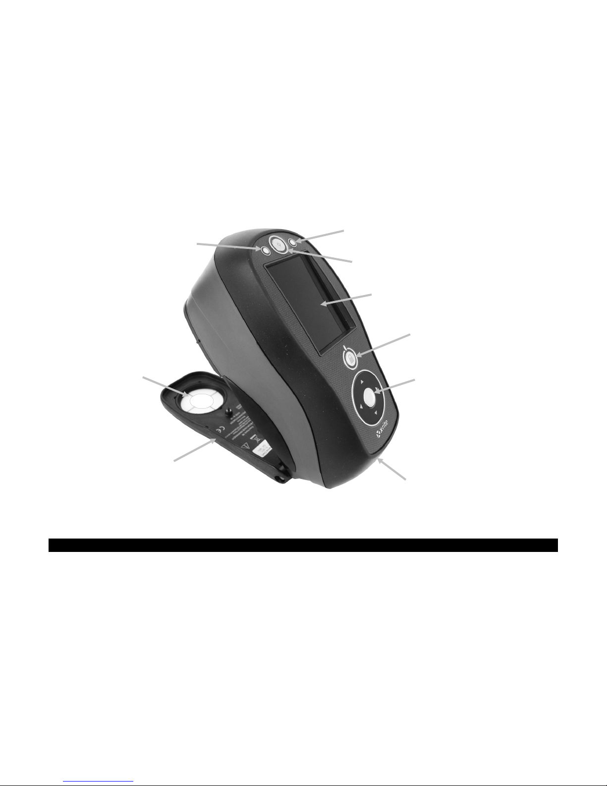
CI62L+RTL SPECTROPHOTOMETER
On/off power and navigation
Measurement status indicator
Select button and navigation control
USB and AC
• Documentation and registration
•
Shoe
Target window
LCD color display
Measurement status indicator
Measurement button
INTRODUCTION AND SETUP
The spectrophotometer is a compact, rugged and reliable color measurement instrument that
reports spectral data.
This manual covers the installation, operation and maintenance of the instrument. Specific
instructions for using the instrument with your software application can be found in the software
documentation.
Key features of the instrument are:
• Hi-resolution 240 x 320, 18-bit color display
• Navigation control for easy screen selections, measure button, and power on/off
control lock button
(up, down, left, and right)
adapter inputs
Packaging
Your instrument packaging should contain all the items listed below. If any of these items are
missing or damaged, contact X-Rite or your Authorized Representative.
• Ci62L+RTL instrument
• Carrying case
• USB interface cable
• AC adapter (X-Rite P/N SE30-277) and line cord
• Calibration reference
material
Safety strap
7
Page 10

CI62L+RTL SPECTROPHOTOMETER
Small loop
Wrist strap
Strap post
Tighten slide
Attaching the Safety Strap
A safety strap is included with your instrument. The strap attaches to the back of the instrument
and around your wrist. The strap should not be used to carry the instrument.
1. Feed the small looped end of the strap around the post at the back of the instrument.
2. Insert the wrist strap end through the small loop.
3. Pull on the wrist strap to secure to the strap post.
4. Use the slide to tighten the strap around your wrist.
8
Page 11

CI62L+RTL SPECTROPHOTOMETER
Power button
Powering Off
The instrument can be
manually powered off by
pressing and hol
power button for three
seconds.
Powering On and Off
The power button is used to initiate the instrument from a power off state. Simply press and hold
the button for three seconds to turn on the instrument. If the instrument does not power up after
pressing the power button, the batteries may require charging. Refer to About the Battery Pack.
ding the
When first powered up, the instrument goes through a diagnostics test and displays a splash
screen before the main menu screen appears.
Splash Screen Main Menu
Locking the Navigation Control
The power button is also used to lock the navigation control. This is useful to avoid inadvertent
contact with the control when taking measurements.
Pressing the power button toggles the navigation control to “locked” and “unlocked.
A padlock icon appears in the header bar of the display to indicate the status of the control.
Locked Control Unlocked Control
9
Page 12

CI62L+RTL SPECTROPHOTOMETER
Cycle Life Characteristics
Cycles
1.0 C Discharge
C/2 Discharge
1.25 A CC/CV Charge, 4.2 V, 3 hrs.
Capacity (Ah)
Power Save Modes
The instrument utilizes two power save modes to conserve battery life during nonuse times.
Standby Mode: The instrument is ready to measure, however the display is not on. A button
press, measurement, power connection (if not connected), or USB connection will wake up the
instrument.
Off Mode: The power button must be pressed to wake up the instrument before a measurement
can be taken. Plugging in the AC adapter will also wake up the instrument from power off mode.
Off mode does not occur when the AC adapter is attached to the instrument.
Charging the Battery Pack
General
The battery pack for your new instrument comes in a low to medium charge state and should be
charged before use (up to 4 hours for full charge).
A charged battery pack may eventually lose partial charge if not used for an extended amount of
time. You should charge the battery from time to time and store in a cool environment when not
in use to maintain battery performance.
Lifespan Expectations
Lithium-ion batteries typically decay to 80% capacity after 400 charge cycles (see chart below). A
charge cycle can be defined as several partial charges equaling 100%. Partial charge and
discharge cycles will help maintain the life of the battery. It is best to avoid full discharge and
charge cycles. After roughly 400 charge cycles are reached, the amount of measurements you
can expect to achieve from one full charge is reduced. At this point, you may wish to replace the
battery pack.
Disposal
Dispose the battery pack in a designated disposal location for recycling.
10
Page 13

CI62L+RTL SPECTROPHOTOMETER
AC adapter
AC Adapter Ratings
Operational hazard exists if an
USB connector
Connecting the AC Adapter
NOTE: The instrument can operate from the AC adapter only. The battery pack does not need to be
installed. The AC adapter (X-Rite P/N SE30-277) overrides any charge condition of the battery pack in the
instrument. Measurements can be taken even with a very low battery condition when using the AC adapter.
1. Verify the voltage indicated on the AC adapter complies with the AC line voltage in your area.
2. Insert the small plug from the AC adapter into the input connector on the instrument.
3. Plug the detachable line cord in the AC adapter and plug the line cord into the wall receptacle.
Input: 100-240V 50-60 Hz
Output: 12VDC @ 2.5A
connector
AC adapter other than X-Rite
SE30-277 is used.
Connecting the USB Cable
IMPORTANT: You must install the software before connecting the instrument to your computer.
1. Install the software application if not already installed. Refer to the software documentation
for additional information.
2. Turn the instrument on and plug the square end of the USB cable into the back of the
instrument.
3. Plug the USB cable into an available port on your computer. The instrument should
acknowledge USB presence by displaying the USB icon in the header bar of the screen.
11
Page 14

CI62L+RTL SPECTROPHOTOMETER
Down control
Right control
Select control
Left control
Up control
Measure button
LED indicator
LED indicator
USER INTERFACE
Instrument Controls
The instrument controls are used to navigate the screen, select options, and perform
measurements.
Navigation Control (up, down, left, right and center)
The navigation control moves the focus of the highlight around the
screen. Tapping on the left side moves the focus to the next
available item to the left. Tapping on the right side moves the focus
to the next available item to the right. The up and down sides
perform the same function, only in an up and down direction.
Tapping on the center of the control selects the item that has focus,
such as a mode or option.
NOTE: If at any time the navigation control become nonresponsive, turning the instrument off and then back on will reset
their operation.
Measure Button
The Measure button is located at the front of the instrument. The
button can be configured to initiate a measurement or be used in
conjunction with the read switch.
You can also use the
navigation control to
rapidly scroll through a list
by touching the control
between the arrows and
circle left or right.
LED Indicators
Multi-color LEDs located at the front of the instrument provide visual feedback on the status of a
measurement. The LEDs will turn off after 5 seconds.
• Green: Indicates a successful measurement has taken place. Flashing green LEDs indicates
that the instrument is at an idle state waiting for a measurement.
• Amber: Indicates a measurement is in progress.
• Red: Indicates a measurement error has occurred.
12
Page 15

CI62L+RTL SPECTROPHOTOMETER
General Sample Measurement
The instrument can take measures from just about any clean, dry surface that is reasonably flat.
The instrument shoe should be able to rest flat and steady on the sample area. If the item to be
measured is smaller than the shoe, you may want to make a platform—at the same height as the
item—for the rest of the instrument’s shoe to sit on.
Procedure:
1. Clear the sample surface of any dirt, dust, or moisture.
2. Position the target window over the sample to measure. If possible, place the entire
instrument on the sample.
3. Press the instrument firmly to the shoe and hold steady until the display indicates that the
measurement is complete.
4. Release the instrument and view the measurement results.
An unsuccessful measurement will be indicated by an error message. See the Troubleshooting
section for more details.
13
Page 16

CI62L+RTL SPECTROPHOTOMETER
Measure mode
Calibration mode
Header bar
Main column
View column
Content area
Progress column
Configuration mode
Main Screen Menu
When the instrument is powered-up, the main (top level) screen appears after the diagnostics
test is complete. The main screen consists of the header bar and operation modes. The operation
modes are selected by using the navigation buttons located to the side of the display screen.
Measure Mode
The measure mode is the main mode of operation. Use the Measure mode to take and analyze
measurements, and select measurement options. Refer to the Measurement Mode section for
information.
Calibration Mode
The calibration mode is used to perform white reference and black trap calibrations. Refer to the
Calibration Mode section for information.
Configuration Mode
The configuration mode is used to set and edit the instruments configuration options. The
configuration options should be set before you use your instrument for the first time. Refer to the
Compare Mode and QA Mode sections for information.
Display Screen Layout
The display screen is divided into five main areas.
14
Page 17

CI62L+RTL SPECTROPHOTOMETER
Indicates the instrument must be pressed to the shoe to activate the read
Indicates the measure button on the top of the instrument must be pressed
Indicates a software command is required to initiate a measurement. No
Indicates that both the read switch and measure button are required to
Indicates the battery pack is fully charged.
Indicates the battery pack has a sufficient charge for a substantial number
Indicates the battery pack is low, but measurements are still possible.
Indicates the battery pack is very low and only a few measurements
Indicates the AC adapter is plugged in and the battery pack is charging
Indicates that battery pack is removed and the instrument is operating
Header Bar
The header bar at the top displays various icons showing the current instrument setup and
condition. Refer below for a description of each.
• Controls Lock: Displays a locked
or unlocked icon for the instrument controls.
Refer to Locking the Navigation Control earlier in this manual for an explanation.
• Measurement Trigger Method: Displays the measurement method currently selected
for the instrument.
switch to take a measurement.
to take a measurement.
read switch or measure button are used.
take a measurement.
• USB Connection: The USB icon appears when the instrument is plugged into the USB
port on the computer.
• Battery Gauge: Depicts the current condition of the battery pack.
of measurements.
Battery pack should be charged soon.
remain. Battery pack should be charged immediately.
(battery indication segments cycle). The battery indicator will stop cycling
and display three segments when the battery pack is fully charged.
from the AC adapter only.
Main Column
The main column is used to access the main instrument screen and configuration mode.
View Column
The view column lists options that may be available for the selected mode. The highlighted option
is the one that is currently displaying in the content area.
Content Area
The content area displays the data, steps, and information.
Progress Column
The progress column displays controls supporting the currently active content area, such as step
sequences, etc.
15
Page 18

CI62L+RTL SPECTROPHOTOMETER
Configuration mode icon
Options column
Instrument information
Available
Value
CONFIGURATION MODE
Configuration mode is used to adjust and view the instrument’s settings. Each configuration
option is explained in detail on the following pages.
Entering Configuration Mode
1. From the Main screen, use the Navigation control to move the highlight focus to the
Configuration icon.
2. Tap the Select button to access the main configuration screen. The screen displays the
instrument information (model, serial number, firmware and certification date).
screen
3. From the Configuration screen, use the Up or Down navigation buttons to move the highlight
focus to the desired configuration icon in the Options column.
NOTE: The arrow icon ( or ) at the end of the Options column indicates that additional
options are available. Move the highlight focus to the arrow icon to advance to the additional
options.
4. Tap the Right navigation button to enter the option settings area.
5. For Option Selections:
Use the Up or Down navigation buttons to move the highlight focus to the desired setting and
tap the Select button to change your setting. An arrow () appears next to the selected
setting.
For Value Selections:
Tap the Select button to activate the parameter and use the Up or Down navigation buttons
to select the value. Tap the Select button to save the value.
settings
selection
6. Tap the Left navigation button to return to the Options column.
16
Page 19

CI62L+RTL SPECTROPHOTOMETER
Main screen icon
Exiting Configuration Mode
After configuring options, use the Left navigation button to move the highlight focus to the Main
screen icon in the Main column and tap the Select button to exit.
NOTE: If a setting has a checkmark save icon it must be selected before exiting or any changes
that were made will be lost.
Measurement Trigger
This option is used to determine which inputs are used to trigger a measurement on the
instrument. The available settings are Software Only, Pressure (default), Button, and Pressure
and Button.
Software Only: No button or read switch is required to take a measurement. This setting would
be selected when software input is used to trigger a measurement.
Pressure: Shoe closing is required to take a measurement.
Button: Measure button is required to take a measurement.
Pressure and Button: Both the read switch and measure button are required to a take a
measurement.
Averaging
This option is used to set the number of measurements required for calculating a single
measurement. Measurements are taken at different locations on a sample to achieve average
measurement values. The available settings are 1 to 99 (default is 3).
Language
This option is used to set the language that is displayed on the instrument. The available
settings are English (default), German, French, Spanish, Italian, Portuguese, Chinese Simplified,
Chinese Traditional, Korean, and Japanese.
Instrument Orientation
This option is used to change the display direction to accommodate both right and left
handed users. The available settings are Right Handed (default) and Left Handed.
17
Page 20

CI62L+RTL SPECTROPHOTOMETER
Date Format
This option is used to adjust the date format the instrument uses. The available settings
are: MM/DD/YYYY (default), DD/MM/YYYY, DD.MM.YYYY, YYYY/MM/DD, and YYYY-MM-DD.
NOTE: The date format automatically changes to the correct format for the selected language. If
desired, you can change the format after selecting the language.
Instrument Date/Time
This option is used to set the instrument date and time.
1. Use the Right/Left and Up/Down buttons the select the month, day, year, hour, or
minute option.
2. Tap the Select button to access the parameter.
3. Use the Up or Down navigation buttons to edit the parameter and then tap the Select
button.
4. Repeat steps 1 through 3 until the date and time are set.
5. Tap the Right navigation button and highlight the checkmark icon
in the Progress
Column.
6. Tap the Select button to save the date and time.
Delete All Samples or Standards
This option is used to delete all samples or standards stored in the instrument. To delete all
samples or standards, tap the Right side of the navigation control and select the desired delete
option. Tap the Right side of the navigation control to move highlight focus to the checkmark
icon in the Progress column. Tap the Select control to delete.
Restore Factory Settings
This option is used to restore the instrument’s configuration settings back to their original
factory settings. All jobs, projects, standards and samples will also be deleted.
To restore the factory settings, tap the Right side of the navigation control to move highlight
focus to the checkmark icon in the Progress column. Tap the Select control.
18
Page 21

CI62L+RTL SPECTROPHOTOMETER
CALIBRATION MODE
The calibration consists of a ceramic plaque for white measurements and a trap opening for black
measurements.
A calibration should be performed when prompted for by the instrument or when desired.
Refer to Cleaning section in the Appendices for information on cleaning the optics area and
references.
NOTE: Make sure to use the calibration reference supplied with the instrument for calibrating.
Do not substitute this reference with a reference from another instrument. The serial number
on the reference should match the serial number on the instrument.
Calibration Notes
• Dirt or dust in the aperture area will cause an inaccurate calibration reading. Refer to the
Appendices for optics cleaning procedure.
• The white ceramic plaque in the calibration reference is dramatically affected by
smudge marks, dust, and finger prints. Refer to Appendices for calibration reference
cleaning procedures.
• The black trap should be cleaned periodically to remove any dust or
contamination. Refer to Appendices for black trap cleaning procedures.
• Do not move instrument while taking a calibration measurement. If motion is
detected, calibration will be aborted.
• Important: If the lamp signal in your instrument reaches a level that is
50% below the factory level stored, the warning symbol shown at the right
appears after a calibration is completed. This indicates that the illumination
level is getting low and you should have your instrument serviced soon.
White and Black Calibration Procedure
1. From the Main screen, use the Navigation control to move the highlight square to the
Calibration icon.
2. Tap the Select control to access the calibration screen.
Calibration Required appears if calibration is needed. If calibration is not currently needed, the
time remaining before the next calibration along with the white reference (plaque) serial
number appears. To exit calibration mode without calibrating, select the Exit icon (x) in the
Progress column.
19
Page 22

CI62L+RTL SPECTROPHOTOMETER
→
Exit icon
Calibration mode
Next icon
White ceramic
plaque
Information that appears
icon
when calibration is not
currently required
3. Use the Right navigation control to move the highlight focus to the Progress column. Use the
Down navigation control to highlight the Next arrow icon (
) if not highlighted and tap the
Select button.
4. Remove the protective cap from the white ceramic plaque in the calibration reference.
5. Position the instrument target window over the white ceramic plaque.
6. Press the instrument firmly to the shoe and hold steady until the display indicates that the
reading is complete. Release the instrument.
7. Reinstall the protective cap on the white ceramic plaque.
8. Position the instrument target window over the black trap opening of the calibration reference.
20
Page 23

CI62L+RTL SPECTROPHOTOMETER
Black trap
opening
9. Press the instrument firmly to the shoe and hold steady until the display indicates that the
reading is complete. Release the instrument.
10. Tap the Select control to save the calibration and exit to the main menu.
11. Store the calibration reference in a dry, dust free area, away from direct exposure to light.
NOTE: If an error message appears during or after white calibration, tap the Select control to
clear the message and try measuring the white reference again. If an error still occurs, clean
the white calibration reference as explained in the Appendices.
21
Page 24

CI62L+RTL SPECTROPHOTOMETER
Icon
Description
Exits the averaging measurement sequence for the current standard or sample.
Toggle between the standard and sample measurement screen.
Used to save the current displayed standard data as a standard to be used in QA
Used to exit a compare standard measurement without saving it as a standard.
COMPARE MODE
The Compare mode is used for comparing measurements without storing the data. If desired,
standards can be saved for use in QA mode (refer to the following pages for additional information
on saving standards). The compare measurement procedure averages three measurements for
each standard and sample. Measurements are taken at various locations on the standard and
sample to achieve average data values.
The first measurement sequence is set as the standard and each measurement sequence
thereafter is compared to it. The standard can be remeasured whenever desired.
After a standard and sample measurement sequence is performed a colored icon appears in the
display, indicating how much variation was in the averaged measurements. A green icon indicates
the variation of the averaged measurements was within the preset limits. A yellow icon indicates
the variation of the averaged measurements was close to the preset limits. A red icon indicates
the variation of the averaged measurements has exceeded the preset limits.
Compare Mode Icons
A description of the icons found in the Compare mode is shown below.
Toggle between L*C*h°, Gloss and Y data views.
mode. This icon only appears after a standard measurement.
Used to confirm a compare standard measurement as a saved standard.
Compare Measurement
To perform a Compare measurement:
1. From the Main screen, use the Navigation control to move the highlight square to the
Measure mode icon.
2. Tap the Select control to access the main measure screen.
3. From the Measure screen, use the Up or Down navigation buttons to move the highlight focus
to the Measurement Mode icon
4. Tap the Select or Right button to access the measurement mode selection area.
22
.
Page 25

CI62L+RTL SPECTROPHOTOMETER
Measurement Mode icon
5. Use the Up or Down navigation buttons to move the highlight focus to the Compare mode.
An arrow () indicates Compare mode is selected.
6. Tap the Select button and the screen returns to the Measure Standard screen.
7. Position the instrument on the first area of the standard and take a measurement. After the
measurement, the instrument displays "Averaged 1 of 3" in the screen, indicating two more
measurements are required for results.
8. Position the instrument on the second area of the standard and take a measurement. After
the measurement, the instrument displays "Averaged 2 of 3" in the screen, indicating one
more measurement is required for results.
9. Position the instrument on the third area of the standard and take a measurement. After the
measurement, the instrument momentarily displays "Processing" and then the averaged
standard data values.
23
Page 26

CI62L+RTL SPECTROPHOTOMETER
Standard Data
Sample Data
Difference Data
Standard/Sample
10. After the standard measurement(s) is complete, position the instrument on the first area of
the sample to compare and take the measurement. After the measurement, the instrument
displays “Averaged 1 of 3" in the screen, indicating two more measurements are required for
results.
11. Position the instrument on the second area of the sample and take a measurement. After the
measurement, the instrument displays "Averaged 2 of 3" in the screen, indicating one more
measurement is required for results.
12. Position the instrument on the third area of the sample and take a measurement. After the
measurement, the instrument momentarily displays "Processing" and then the averaged
sample data values and difference values.
13. Continue with additional sample measurements if required.
Measuring a Different Standard
1. Tap the Right navigation button to highlight the Progress column.
2. Use the Up or Down navigation buttons to select the Standard/Sample toggle icon
toggle icon
24
.
Page 27

CI62L+RTL SPECTROPHOTOMETER
Save standard icon (only appears
after a standard measurement)
3. Tap the Select button to change to the Measure Standard screen.
4. Measure the standard.
Tapping the Select button with the Standard/Sample icon highlighted will toggle the
measurement screen between Measure Standard and Measure Sample.
Saving a Standard
1. Tap the Right navigation button to highlight the Progress column.
2. Use the Up or Down navigation buttons to select the Save Standard icon
3. Tap the Select button to open the confirm screen to save the standard.
.
4. Tap the Right navigation button and highlight the Checkmark icon
Column.
5. Tap the Select button to save the standard. By default, a saved standard is named “Standard”
with the next available number (e.g., Standard1, Standard2, etc.).
NOTE: To exit the without saving, highlight the Exit
Select button.
in the Progress
icon in the Progress Column and tap the
25
Page 28

CI62L+RTL SPECTROPHOTOMETER
Icon
Description
Access standard detail, selection, and edit screen. Arrow points to current standard
Exits the averaging measurement sequence for the current sample.
Toggle between L*C*h°, Gloss and Y data views.
Toggle between the current standard and sample measurement screen.
QA MODE
The QA measurement mode is the main mode of operation. Sample measurements are compared
to stored standards and the results displayed. The QA measurement procedure requires three
measurements for each sample. Measurements are taken at various locations on the sample to
achieve average data values. Stored measurement data can then be uploaded for further
analysis.
QA Mode Icons
A description of the icons found in the QA mode is shown below.
Access project detail, selection, and creation screen. Arrow points to current project
selected.
selected.
QA Measurement
To perform a QA measurement:
1. From the Main screen, use the Navigation control to move the highlight square to the
Measure mode icon.
2. Tap the Select control to access the main measure screen.
3. From the Measure screen, use the Up or Down navigation buttons to move the highlight focus
to the Measurement Mode icon
4. Tap the Select or Right button to access the measurement mode selection area.
5. Use the Up or Down navigation buttons to move the highlight focus to the QA mode.
6. Tap the Select button. An arrow () appears next to the QA mode and the screen returns to
the measure screen.
.
26
Page 29

CI62L+RTL SPECTROPHOTOMETER
Measurement Mode icon
Current standard and
project selected
7. Select a project (if required).
8. Select the standard that will be used for the sample measurement.
9. Position the instrument on the first area of the sample and take a measurement. After the
measurement, the instrument displays "Averaged 1 of 3" in the screen, indicating two more
measurements are required for results.
10. Position the instrument on the second area of the sample and take a measurement. After the
measurement, the instrument displays "Averaged 2 of 3" in the screen, indicating one more
measurement is required for results.
11. Position the instrument on the third area of the sample and take a measurement. After the
measurement, the instrument momentarily displays "Processing" and then the averaged
sample data values and difference values.
27
Page 30

CI62L+RTL SPECTROPHOTOMETER
Sample data
Difference data
Measurement timestamp
NOTE: If an error occurs during a measurement, try measuring the
sample again. If the error still occurs, refer to the Troubleshooting
section in the Appendices.
28
Page 31

CI62L+RTL SPECTROPHOTOMETER
ADVANCED FEATURES
This section covers the procedures for editing standards and creating projects.
Standards
QA standards can be deleted, renamed, and tolerances edited after they are created in Compare
Mode. Refer to the following pages for the procedures.
Deleting a Standard
To delete a standard:
1. Select the standard (if not already selected) that you want to delete and move the highlight to
the Progress Column.
2. Highlight the Delete icon
3. Highlight the Checkmark icon
4. Tap the Select button to delete the selected standard.
Editing Standard Name
To rename a standard:
1. Select the standard (if not already selected) that you want to rename and move the highlight
to the Progress Column.
2. Highlight the Edit icon
and tap the Select button to display the Delete Standard screen.
in the Progress Column on the confirm screen.
and tap the Select button to view the tolerance screen.
3. Select the Edit icon
and tap the Select button to enter the standard name screen.
29
Page 32

CI62L+RTL SPECTROPHOTOMETER
Access the editing screen where the standard is edited including the name.
Exit the editing screen and return to the standard selection screen.
NOTE: Select the backspace character () and use the Left navigation button to delete the
unwanted characters.
4. Use the Left or Right navigation buttons to move the two arrows to character location and
tap the Select button.
5. Use the Up or Down navigation buttons to page through the alphanumeric list for the
character location of the name.
NOTE: You can also use the navigation control to rapidly scroll through a list by touching the
control between the arrows and circle left or right.
6. Tap the Select button set the character.
7. Tap the Left or Right navigation button to move the two arrows to the next character space
and tap the Select button.
8. Use the Up or Down navigation buttons as previously explained to set the character and tap
the Select button.
9. Continue until all characters for the name are set.
10. Tap the Right navigation button and highlight the Checkmark icon
in the Progress
Column.
11. Tap the Select button to save the name for the standard.
Editing Standard Tolerances
Tolerances for newly created standards can be edited. Up to six tolerances can be created for
each standard.
The tolerance limit is the maximum allowable difference from the standard color values that is
considered acceptable. The tolerances are used to test your sample’s acceptability by displaying a
pass or fail signal, based on the pass/fail margin limits. Plus and minus limits can be set
symmetrically or individually for allowable color space attributes. Pass/fail indication appears in
QA function when set.
Tolerance Editing Icons
Descriptions of the various icons found for tolerance editing are shown below.
30
Page 33

CI62L+RTL SPECTROPHOTOMETER
Indicates that the tolerance plus and minus attributes change symmetric (locked)
Indicates that the tolerance plus and minus attributes change asymmetric (not
Access previous screen when browsing tolerances.
Access next screen when browsing tolerances.
Save changes to the current tolerance screen edits.
Selected tolerance type
when edited.
locked) when edited.
Editing Tolerances
To edit standard tolerances:
1. Select the standard (if not already selected) that you want edit and move the highlight to the
Progress Column.
2. Highlight the Edit icon
and tap the Select button to view the tolerance screen.
3. Use the navigation control to highlight the tolerance type option. A box outline indicates that it
is selected.
4. Tap the Select button to access the option.
5. Use the Up or Down navigation buttons to select the tolerance type.
6. Tap the Select button to set the tolerance type.
7. Use the navigation control to highlight illum/obs, SPIN/SPEX, or +/-tolerance value.
NOTE: Make sure the symmetric icon
is displayed if +/- tolerance attribute values are
going to be set as the same value. Highlighting the icon and tapping the Select button will
toggle between the two options.
8. Tap the Select button to access the option and use the Up or Down navigation buttons to
select option/value.
9. Tap the Select button to set the tolerance option/value.
10. Continue until all attributes for the first tolerance are set.
11. Tap the Right navigation button and highlight the checkmark icon
12. Tap the Select button to save the edits for the first tolerance set.
in the Progress Column.
31
Page 34

CI62L+RTL SPECTROPHOTOMETER
Project icon
Available Projects
NOTE: If additional tolerance sets (up to six) are required for the selected standard, highlight the
right arrow icon
is the Progress bar and tap the Select button. Edit the next tolerance set as
explained above.
Projects
The project icon lists available projects that contain grouped standards. You must select the
desired project that the sample measurements are stored in before taking measurements. The
selected project is used until a different project is chosen. Projects are created and standards
added using the instrument. Refer to the procedures that follow.
Selecting a Project
To select a project:
1. From the Measure screen, use the Up or Down navigation buttons to move the highlight focus
to the Project icon
.
2. Tap the Select or Right button to access the project selection area.
3. Use the Up or Down navigation buttons to move the highlight focus to the desired project.
4. Tap the Select button. An arrow () appears next to the selected project and the screen
returns to the measure screen.
Creating a Project
To create a project:
1. From the Measure screen, use the Up or Down navigation buttons to move the highlight focus
to the Project icon
.
2. Tap the Right button twice to move the focus to the Progress Column.
3. Select the Add icon
and tap the Select button to view the Add Project screen.
32
Page 35

CI62L+RTL SPECTROPHOTOMETER
4. Tap the Left navigation button to move the highlight to the Add Project screen.
5. Tap the Select button to access the option.
6. Use the Up or Down navigation buttons to page through the alphanumeric list for the first
character of the name.
NOTE: You can also use the navigation control to rapidly scroll through a list by touching the
control between the arrows and circle left or right.
7. Tap the Select button set the first character.
8. Tap the Right navigation button to move the two arrows to the next character space and tap
the Select button.
9. Use the Up or Down navigation buttons as previously explained to set the character and tap
the Select button.
10. Continue until all characters for the name are set.
11. Tap the Right navigation button and highlight the Checkmark icon
in the Progress
Column.
12. Tap the Select button to save the name for the project.
NOTE: To exit the name without saving, highlight the Exit
icon in the Progress Column and
tap the Select button.
Adding Standards to a Project
Standards that are available on the instrument can be grouped into specific projects.
To add standards:
1. Select a project as previously explained and then tap the Right navigation button. Highlight
the Edit
icon in the Progress Column.
2. Tap the Select button and highlight the Standard
icon in the Progress Column.
33
Page 36

CI62L+RTL SPECTROPHOTOMETER
3. Tap the Select button and then tap the Left navigation button to move the highlight to the
select standards screen.
4. Use the Up or Down navigation buttons and the Select button to choose the standards.
5. When finished, tap the Right navigation button and highlight the Checkmark icon
in the
Progress Column.
6. Tap the Select button to save the standards for the project.
Deleting Projects, Standards, and Samples
Projects, standards and samples can be deleted from the instrument. When a project is deleted,
any standard or samples included are also deleted.
To delete a project, standards or samples:
1. Select a project as previously explained and then tap the Right navigation button. Highlight
the Edit
icon in the Progress Column.
2. Tap the Select button and then tap the Left navigation button to move the highlight to the
select option screen.
3. Use the Up or Down navigation buttons to choose Delete All Standards, Delete All Samples,
or Delete This Project. Tap the Select button to choose the option.
4. Tap the Right navigation button and highlight the Checkmark icon
in the Progress
Column.
5. Tap the Select button to delete the selected option.
Locking a Project
After a project is created it can be locked to help prevent any inadvertently deleting of standards
and samples.
To lock a project:
1. Select a project as previously explained and then tap the Right navigation button. Highlight
the Edit
icon in the Progress Column.
2. Tap the Select button and then tap the Left navigation button to move the highlight to the
select option screen.
3. Use the Up or Down navigation buttons to choose the Lock Project option. Tap the Select
button to choose the option.
4. Tap the Right navigation button and highlight the Checkmark icon
in the Progress
Column.
5. Tap the Select button to lock the project.
Unlocking a Project
Projects can be unlocked by selecting the Unlock Project option after the project is locked.
Editing Project Name
To rename a project:
1. Select the project (if not already selected) that you want to rename and move the highlight to
the Progress Column.
34
Page 37

CI62L+RTL SPECTROPHOTOMETER
2. Highlight the Edit icon and tap the Select button to view the select option screen.
3. Select the Edit icon
and tap the Select button to view the Enter Project Name screen.
4. Tap the Left navigation button to move the highlight to the Enter Project Name screen.
NOTE: Select the backspace character () and use the Left navigation button to delete the
unwanted characters.
5. Use the Left or Right navigation buttons to move the two arrows to the character location
and tap the Select button.
6. Use the Up or Down navigation buttons to page through the alphanumeric list for the
character location of the name.
NOTE: You can also use the navigation control to rapidly scroll through a list by touching the
control between the arrows and circle left or right.
7. Tap the Select button set the character.
8. Tap the Left or Right navigation button to move the two arrows to the next character space
and tap the Select button.
9. Use the Up or Down navigation buttons as previously explained to set the character and tap
the Select button.
10. Continue until all characters for the name are set.
11. Tap the Right navigation button and highlight the Checkmark icon
in the Progress
Column.
12. Tap the Select button to save the name for the project.
35
Page 38

CI62L+RTL SPECTROPHOTOMETER
APPENDICES
Service Information
X-Rite provides repair service to their customers. Because of the complexity of the circuitry, all
warranty and non warranty repairs should be referred to an authorized service center. For non
warranty repairs, the customer shall pay shipping and repair cost to the authorized service
center, and the instrument shall be submitted in the original carton, as a complete unaltered unit,
along with all the supplied accessories.
X-Rite, Incorporated has offices around the world. You can contact us using one of the following
methods:
• To identify the X-Rite service center nearest you, please visit our web site at:
www.xrite.com.
• For online help, visit our web site (www.xrite.com) and click the Support link. Here you can
search for software or firmware updates, white papers, or frequently asked questions
which can quickly resolve many common user problems.
• Send an e-mail to Technical Support: casupport@xrite.com detailing your problem and listing
your contact information.
• For sales questions or to order cables and accessories, visit our web site (www.xrite.com) or
contact your nearest X-Rite dealer or service center.
• Problems and questions can also be faxed to your local X-Rite office listed on our web site.
36
Page 39

CI62L+RTL SPECTROPHOTOMETER
Cleaning the Instrument
Your instrument requires very little maintenance to achieve years of reliable operation. However,
to protect your investment and maintain reading accuracy, a few simple-cleaning procedures
should be performed from time to time.
General Cleaning
The exterior of the instrument may be wiped clean with a cloth dampened in water or mild
cleaner.
NOTE: DO NOT use any solvents to the clean the instrument, this will cause damage to the
cover.
Cleaning the Optics
The optics should be cleaned once a week in a normal environment. If the instrument is used in a
dirty or dusty environment, more frequent cleaning may be required.
Carefully lift the instrument, open the shoe and blow short bursts of clean, dry air into the
measurement port. This should remove any accumulated debris from the optics.
IMPORTANT: If can air is used for cleaning, do not invert or tilt the can during use. This could
cause damage to the optics.
37
Page 40

CI62L+RTL SPECTROPHOTOMETER
Protective cap
Ceramic plaque
Align arrows
Large notch
Cleaning the Calibration Reference
The calibration reference consists of white and green ceramic plaques, and a black trap opening.
The calibration reference should be cleaned periodically.
Ceramic Plaque Cleaning Procedure
1. Remove the protective plastic cap from the ceramic plaque.
2. Important: Always grip the ceramic plaque from the edges, being careful not to touch the
white/green surface.
Press downward on the ceramic plaque and turn counterclockwise until it stops. Lift upward
and remove the ceramic plaque from the base.
3. Clean the plaque using a mild soap and warm water solution. Thoroughly rinse with warm
water and wipe dry with a lint-free cloth. Do not use solvents or cleaners of any kind.
4. After the ceramic plaque is completely dry, align the large tab on the side of the ceramic
plaque with the large notch in the base. Compress the spring downward with the ceramic
plaque until it stops. Holding the ceramic plaque down, rotate clockwise until it stops. Slowly
allow the plaque to rise. The arrow on the ceramic plaque and the arrow on the base should
be aligned when properly positioned.
5. Reinstall the protective cap over the ceramic plaque when not in use.
38
Page 41

CI62L+RTL SPECTROPHOTOMETER
White ceramic plaque with
Locking tabs
Alignment arrows
Black Trap Cleaning Procedure
1. Take apart the two sections by compressing the two locking tabs on both sides with your
fingers and separating.
2. Clean with clean, dry air, or wipe clean with a lint-free cloth to remove any dust or
contamination.
protective cap
3. After cleaning, align the two arrows on the end before reassembling the sections.
Note: The tabs will not lock correctly if assembled in the opposite direction.
39
Page 42

CI62L+RTL SPECTROPHOTOMETER
Access cover
Latch
Battery contact
Replacing the Battery Pack
Use the rechargeable Li-ion battery pack provided (X-Rite P/N SE15-40); other types may
burst causing personal injury.
1. Carefully turn the instrument over and rotate the shoe back until it is completely open.
2. Using your finger, pull back on the battery access cover latch while lifting upwards on the
cover to remove it from the instrument housing.
3. Remove the old battery pack and dispose in a designated disposal location for recycling.
4. Insert the new battery pack into the instrument with the battery contacts facing down and
towards the back of the instrument.
end
5. Reinstall the battery access cover by inserting the back edge first and then pressing downward
until the access cover locks into position.
6. Return the shoe to the closed position.
40
Page 43

CI62L+RTL SPECTROPHOTOMETER
Problem
Cause/Solution
Instrument not
Battery pack is very low or bad.
Measurement error or
Measurement or calibration failed.
Navigation control
Turn the instrument off and then back on to reset their operation.
Calibration procedure
Calibration reference is dirty or damaged.
Instrument and
Interface cable not connected.
Sample Error
Me
Troubleshooting
Prior to contacting the support department for instrument problems, try the applicable solution(s)
described below. If the condition persists, contact us using one of the methods listed in the Service
Information section.
responding (no
display or beep
during
measurements).
results appear
inaccurate.
buttons are nonresponsive.
fails.
software not
communicating.
Charge the battery. If battery pack is bad, replace using the procedure in
the Appendix.
No battery pack installed.
Install batteries or plug in AC adapter.
If error persists, clean instrument optics and calibration reference (see
General Cleaning).
Turn instrument power off and then on.
Clean the reference per procedure in Appendix, or replace if damaged.
Connect the interface cable between the computer and the instrument.
Close and restart the software application. If this does not work, reboot
the computer.
Remove power from the instrument, reapply power and see if the condition
is corrected.
Check for proper configuration setting from the software provider.
Repeated sample
measurement
failures.
Ensure that the sample is being read in accordance with your software’s
documentation.
Close and restart the software application.
Perform a calibration on the instrument (see Calibration section).
Screen Messages
Screen messages can appear on the display during error conditions or for informational purposes.
Messages may also be accompanied by a number to indicate a specific condition. If an error
condition persists, please contact our technical support using one of the methods listed in the
Service Information section.
ssage
41
Page 44

CI62L+RTL SPECTROPHOTOMETER
Technical Specifications
Measurement Geometrics d/8°, DRS spectral engine, choice of optical aperture:
14 mm measurement area/20 mm target window
Receiver Blue-enhanced silicon photodiodes
Light Source Gas-filled tungsten lamp
Illuminant Type A, C, D50, D55, D65, F2, F7, F11, and F12
Standard Observer 2° and 10°
Spectral Range 400nm – 700nm
Spectral Interval 10nm – measured, 10nm – output
Measurement Range 0 to 200% reflectance
Measuring Time Approx. 2 seconds
Inter-Instrument Agreement CIE L*a*b*:
Avg. 0.20 ∆E*ab, based on avg. of 12 BCRA series II tiles
(specular component included)
Max. 0.40 ∆E*ab on any tile (specular component included)
Short-Term Repeatability .05 ∆E*ab on white ceramic (standard deviation)
Lamp Life Approx. 500,000 measurements
Power Supply Removable Li-ion battery pack;
7.4 VDC rated @ 2400 mAh
AC Adapter Requirements Input 100-240 VAC, 50/60Hz
Output 12 VDC @ 2.5 A
Charge Time Approx. 4 hours – 100% capacity
Measurements Per Charge 1,000 measurements typical
Data Interface USB 2.0
Operating Temperature Range 50° to 104°F (10° to 40°C) 85% relative humidity maximum
(non-condensing)
Storage Temperature Range -4° to 122°F (-20° to 50°C)
Dimensions 4.3”H (10.9 cm) 3.6”W (9.1 cm) 8.4”L (21.3 cm)
Weight 2.32 lbs. (1.05 kg)
Accessories Provided Calibration Standard, Manual,
AC Adapter, Carrying Case
Usage Indoor only
Altitude 2000m
Pollution Degree 2
Overvoltage Category II
Specifications and design subject to change without notice.
42
Page 45

CI62L+RTL SPECTROPHOTOMETER
Green tile
Protective cap
Green Tile Color Check
1. Perform a calibration procedure if you have not already done so. Refer to the Calibrating section.
2. Select the appropriate option in the application to initiate the green tile color check.
3. Remove the protective cap from the green tile in the calibration reference.
4. Position the instrument’s target window over the green tile.
5. Press the instrument firmly to the shoe. Hold steady until the display indicates that reading is
complete.
6. Release the instrument.
7. Reinstall the protective cap on the green tile.
8. Store the calibration reference in a dry, dust free area, away from direct exposure to light.
43
Page 46

Page 47

Page 48

Page 49

Corporate Headquarters
X-Rite, Incorporated
4300 44th Street SE
Grand Rapids, Michigan 49512
Phone 1 800 248 9748 or 1 616 803 2100
Fax 1 800 292 4437 or 1 616 803 2705
European Headquarters
X-Rite Europe GmbH
Althardstrasse 70
8105 Regensdorf
Switzerland
Phone (+41) 44 842 24 00
Fax (+41) 44 842 22 22
Asia Pacific Headquarters
X-Rite Asia Pacific Limited
Suite 2801, 28th Floor, AXA Tower
Landmark East, 100 How Ming Street
Kwun Tong, Kowloon, Hong Kong
Phone (852) 2568 6283
Fax (852) 2885 8610
Please visit www.xrite.com
for a local office near you.
P/N Ci62L+RTL EN Rev. B
 Loading...