

Page 1
Ci51/Ci52
Spectrophotometer
User Guide
Page 2

Page 3
Ci51/Ci52 S P ECTROPHOTOMETER
Consult this documentation in all cases where the Attention symbol appears.
This symbol is used to inform you of any potential HAZARD or actions that may require
your attention.
CE Declaration
Hereby, X-Rite, Incorporated, declares that this Ci5X Series is in compliance with the essential
requirements and other relevant provisions of Directives 2014/35/EU (LVD), 2014/30/EU (EMC), and
RoHS 2011/65/EU.
Federal Communications Commission Notice
NOTE: This equipment has been tested and found to comply with the limits for a Class A
digital device, pursuant to Part 15 of the FCC Rules. These limits are designed to provide
reasonable protection against harmful interference when the equipment is operated in a
commercial environment. This equipment generates, uses, and can radiate radio
frequency energy and, if not installed and used in accordance with the instruction manual,
may cause harmful interference to radio communications. Operation of this equipment in
a residential area is likely to cause harmful interference in which case the user will be
required to correct the interference at his own expense.
Industry Canada Compliance Statement
This Class A digital apparatus complies with Canadian ICES-003.
Cet appareil numérique de la classe A est conforme à la norme NMB-003 du Canada.
Equipment Information
Use of this equipment in a manner other than that specified by X-Rite, Incorporated may
compromise design integrity and become unsafe.
WARNING: This instrument is not for use in explosive environments.
Do not look directly into the measurement optics when the instrument is on.
Instructions for disposal: Please dispose of Waste Electrical and Electronic Equipment (WEEE) at
designated collection points for the recycling of such equipment
1
Page 4

Ci51/C i 52 S P ECTROPHOTOMETER
Proprietary Notice
The information contained in this manual is copyrighted information proprietary to X-Rite,
Incorporated.
Publication of this information does not imply any rights to reproduce or use it for purposes other
than installing, operating, or maintaining this instrument described herein. No part of this manual
may be reproduced, transcribed or translated into any language or computer language in any
form or by any means: electronic, magnetic, mechanical, optical, manual, or otherwise; without
the prior written permission of an authorized officer of X-Rite, Incorporated.
Patents: www.xrite.com/ip
“© 2017, X-Rite, Incorporated. All rights reserved”
X-Rite® is a registered trademark of X-Rite, Incorporated. All other logos, brand names, and product names mentioned are the properties
of their respective holders.
Warranty Information
X-Rite, Incorporated (“X-Rite”) warrants each instrument manufactured to be free of defects in
material and workmanship for a period of 12 months*. This warranty shall be fulfilled by the
repair or replacement, at the option of X-Rite, of any part or parts, free of charge including labor,
F.O.B. its factory or authorized service center.
X-Rite warrants this Product against defects in material and workmanship for a period of twelve
(12) months from the date of shipment from X-Rite’s facility, unless mandatory law provides for
longer periods. During such time, X-Rite will either replace or repair at its discretion defective
parts free of charge.
X-Rite’s warranties herein do not cover failure of warranted goods resulting from: (i) damage
after shipment, accident, abuse, misuse, neglect, alteration or any other use not in accordance
with X-Rite’s recommendations, accompanying documentation, published specifications, and
standard industry practice; (ii) using the device in an operating environment outside the
recommended specifications or failure to follow the maintenance procedures in X-Rite’s
accompanying documentation or published specifications; (iii) repair or service by anyone other
than X-Rite or its authorized representatives; (iv) the failure of the warranted goods caused by
use of any parts or consumables not manufactured, distributed, or approved by X-Rite; (v) any
attachments or modifications to the warranted goods that are not manufactured, distributed or
approved by X-Rite. Consumable parts and Product cleaning are also not covered by the
warranty.
X-Rite‘s sole and exclusive obligation for breach of the above warranties shall be the repair or
replacement of any part, without charge, which within the warranty period is proven to X-Rite‘s
reasonable satisfaction to have been defective. Repairs or replacement by X-Rite shall not revive
an otherwise expired warranty, nor shall the same extend the duration of a warranty.
Customer shall be responsible for packaging and shipping the defective product to the service
center designated by X-Rite. X-Rite shall pay for the return of the product to Customer if the
shipment is to a location within the region in which the X-Rite service center is located. Customer
shall be responsible for paying all shipping charges, duties, taxes, and any other charges for
products returned to any other locations. Proof of purchase in the form of a bill of sale or
receipted invoice which is evidence that the unit is within the Warranty period must be presented
to obtain warranty service. Do not try to dismantle the Product. Unauthorized dismantling of the
2
Page 5

Ci51/Ci52 S P ECTROPHOTOMETER
equipment will void all warranty claims. Contact the X-Rite Support or the nearest X-Rite Service
Center, if you believe that the unit does not work anymore or does not work correctly.
THESE WARRANTIES ARE GIVEN SOLELY TO BUYER AND ARE IN LIEU OF ALL OTHER
WARRANTIES, EXPRESSED OR IMPLIED, INCLUDING BUT NOT LIMITED TO THE IMPLIED
WARRANTIES OF MERCHANTABILITY, FITNESS FOR A PARTICULAR PURPOSE OR APPLICATION,
AND NON-INFRINGEMENT. NO EMPLOYEE OR AGENT OF X-RITE, OTHER THAN AN OFFICER OF
X-RITE, IS AUTHORIZED TO MAKE ANY WARRANTY IN ADDITION TO THE FOREGOING.
IN NO EVENT WILL X-RITE BE LIABLE FOR ANY OF BUYER’S MANUFACTURING COSTS,
OVERHEAD, LOST PROFITS, GOODWILL, OTHER EXPENSES OR ANY INDIRECT, SPECIAL,
INCIDENTAL OR CONSEQUENTIAL DAMAGES BASED UPON BREACH OF ANY WARRANTY, BREACH
OF CONTRACT, NEGLIGENCE, STRICT TORT, OR ANY OTHER LEGAL THEORY. IN ANY EVENT OF
LIABILITY, X-RITE’S MAXIMUM LIABILITY HEREUNDER WILL NOT EXCEED THE PRICE OF THE
GOODS OR SERVICES FURNISHED BY X-RITE GIVING RISE TO THE CLAIM.
3
Page 6

Ci51/C i 52 S P ECTROPHOTOMETER
Table of Contents
Introduction and Setup 5
Packaging 5
Attaching the Cord Strain Relief 6
Connecting the AC Adapter 8
Connecting the USB Cable 8
Power Button 9
Instrument Indicators 9
Calibrating 10
Calibration Notes 10
Calibration Procedure 10
Taking Measurements 12
Sample Criteria 12
Measurement Techniques 12
Appendices 13
Service Information 13
Cleaning the Instrument 14
General Cleaning 14
Cleaning the Optics 14
Cleaning the Calibration Reference 15
Troubleshooting 17
Technical Specifications 18
Green Tile Color Check (Ci52 only) 19
4
Page 7
Ci51/Ci52 S P ECTROPHOTOMETER
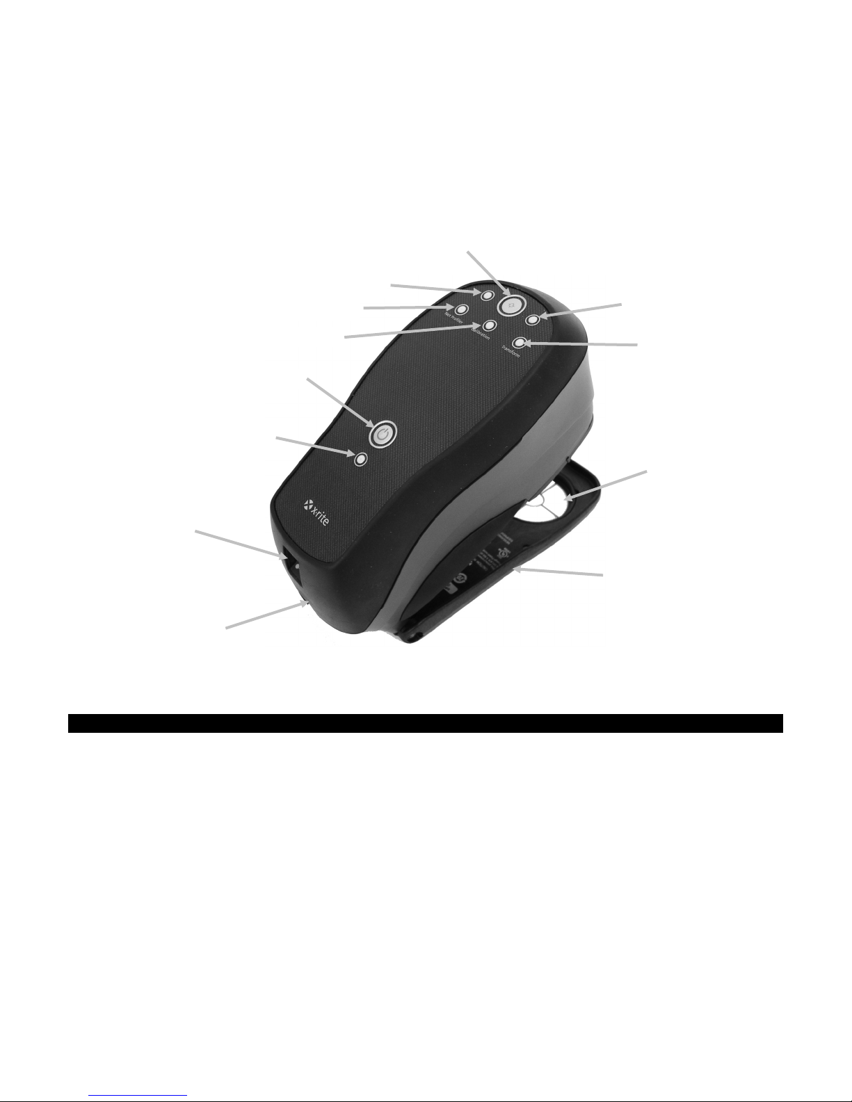
On/off power button
Measurement indicator
USB input
Shoe
Target window
Measurement indicator
Measurement button
Calibration indicator
Transform indicator
Power indicator
Net Profiler indicator
AC adapter
INTRODUCTION AND SETUP
The spectrophotometer is a compact, rugged and reliable color measurement instrument that
reports spectral data to a computer.
This manual covers the installation, basic operation and maintenance of the instrument. Specific
instructions for using the instrument with your software application can be found in the software
documentation.
input
Packaging
Your instrument packaging should contain all the items listed below. If any of these items are
missing or damaged, contact X-Rite or your Authorized Representative.
• Ci51 or Ci52 instrument
• USB interface cabling
• AC adapter (X-Rite P/N SE30-277) and line cord
• Cord strain relief with strap
• Calibration reference
• Manuals & utilities CD
• Documentation and registration material
5
Page 8

Ci51/C i 52 S P ECTROPHOTOMETER
Looped end
Securing post
Shrink wrapped
connection
Small hole
Looped end over 3 rings
Strap
Strain relief
Attaching the Cord Strain Relief
A cord strain relief and strap is supplied to help prevent
inadvertent cord disconnection during instrument use.
1. Attach the strap to the strain relief by inserting one of the looped ends into the small hole, and
then through the other looped end to tighten.
2. Insert the looped end of the strain relief strap into one side of the post at the back of the
instrument, and then out the other side. Note: You may need to use a small pointed object to
pull the loop around the post.
3. Continue pulling the looped end of the strap until the thicker shrink wrapped connection in the
middle passes around the post.
4. Next, insert the looped end of the strap through the small hole in the strain relief, and then
pass it over the 3 rings of the strain relief back towards the small hole.
6
Page 9

Ci51/Ci52 S P ECTROPHOTOMETER
Three rings
Strain relief strap
USB plug
AC adapter plug
Properly connected
5. Pull the strain relief away from the instrument, allowing the looped end to tighten around the
small hole. The shrink wrapped connection in the middle of the strap needs to pass back
around the post. The strap should now be doubled, making it half of its original length.
strain relief
6. Feed the AC adapter plug and USB plug through the 3 rings of the strain relief.
7. Pull the cords through the 3 rings until there is some slack in the cords when they are plugged
in, and when the strain relief strap is pulled tight.
7
Page 10

Ci51/C i 52 S P ECTROPHOTOMETER
AC adapter
connector
AC Adapter Ratings
Operational hazard exists if an
USB connector
Connecting the AC Adapter
1. Verify the voltage indicated on the AC adapter complies with the AC line voltage in your area.
2. Insert the small plug from the AC adapter into the input connector on the instrument.
3. Plug the detachable line cord in the AC adapter and plug the line cord into the wall receptacle.
Input: 100-240V 50-60 Hz
Output: 12VDC @ 2.5A
AC adapter other than X-Rite
SE30-277 is used.
Connecting the USB Cable
IMPORTANT: You must install the instrument driver before connecting the instrument to your computer.
1. Install the software application if not already installed. Refer to the software documentation
for additional information.
2. Plug the square end of the USB cable into the back of the instrument.
3. Plug the USB cable into an available port on your computer.
8
Page 11

Ci51/Ci52 S P ECTROPHOTOMETER
Power button
Power indicator
Power Button
The power button can be used to wake the instrument after it goes into a power down state. A
power on condition is designated by a solid green power indicator. Simply press the power button
to wake the instrument. A power down state occurs after five minutes of non use, and is
designated by a flashing green power indicator.
Instrument Indicators
The LED indicators convey a variety of instrument conditions, such as calibration status,
measurement status, etc. Below is description for each color displayed by the instrument
indicators during operation.
Measurement
• Solid Amber: Measurement in progress
• Solid Green: Successful measurement was taken
• Solid Red: Measurement failed
Calibration
• Solid Red: Calibration is required
• Solid Green: Calibration is not required at this time
NetProfiler
• Indicator Off: NetProfiler feature is not enabled
• Solid Green: NetProfiler subscription is currently activated
• Solid Amber: The profile has expired and updating is required
Transform
• Indicator Off: Transform feature in not enabled
• Solid Green: Transform feature is activated
9
Page 12

Ci51/C i 52 S P ECTROPHOTOMETER
White ceramic plaque
Protective cap
CALIBRATING
The software application prompts for an instrument calibration when required. The frequency at
which this occurs depends on the application. Refer below for procedure.
The calibration reference consists of a ceramic disk for white calibration measurements, and a
trap opening for black calibration measurements. The instrument shoe fits snuggly in both
positions.
Refer to Cleaning section in the Appendices for information on cleaning the optics area and
references.
NOTE: Make sure to use the calibration reference supplied with the instrument for calibrating.
Do not substitute this reference with a reference from another instrument. The serial number
on the reference should match the reference (plaque) serial number on the instrument.
Calibration Notes
• Dirt or dust in the aperture area will cause an inaccurate calibration reading. Refer to the
Appendices for optics cleaning procedure.
• The white ceramic plaque in the calibration reference is dramatically affected by
smudge marks, dust, and finger prints. Refer to Appendices for calibration reference
cleaning procedures.
• The black trap should be cleaned periodically to remove any dust or
contamination. Refer to Appendices for black trap cleaning procedures.
• Do not release the instrument while taking a calibration measurement. If the
instrument is released, calibration will be aborted.
Calibration Procedure
1. When a calibration is prompted for by the application, select the appropriate option to initiate
the calibration.
2. Remove the protective cap from the white ceramic plaque in the calibration reference.
3. Position the instrument’s target window over the white ceramic plaque.
10
Page 13

Ci51/Ci52 S P ECTROPHOTOMETER
Black trap opening
4. Press the instrument firmly to the shoe. Hold steady until the measurement status indicators
change to amber and then green. The calibration indicator should change to red.
5. Release the instrument.
6. Reinstall the protective cap on the white ceramic plaque.
7. Position the instrument target window over the black trap opening in the calibration reference.
8. Press the instrument firmly to the shoe. Hold steady until the measurement indicators change
to amber and then green, and the calibration indicator changes to green. This is an indication
that the calibration procedure was successful.
9. Release the instrument.
10. Store the calibration reference in a dry, dust free area, away from direct exposure to light.
11
Page 14

Ci51/C i 52 S P ECTROPHOTOMETER
Measure button
OR
TAKING MEASUREMENTS
You should refer to the documentation for the software program that you are using with your
instrument. All applications that use the instrument must be running during measurements.
Sample Criteria
The instrument can take measures from just about any clean, dry surface that is reasonably flat.
The instrument shoe should be able to rest flat and steady on the sample area. If the item to be
measured is smaller than the shoe, you may want to make a platform—at the same height as the
item—for the rest of the instrument’s shoe to sit on.
NOTE: Never measure wet paint. Wet paint will contaminate the instrument.
Measurement Techniques
1. Clear the sample surface of any dirt, dust, or moisture.
2. Position the target window over the sample to measure. If possible, place the entire
instrument on the sample.
3. Press the instrument firmly to the shoe; the measurement indicators change to amber. Hold
steady until the measurement indicators change to green followed by an audible beep. This is
an indication that the measurement was successful.
NOTE: Your application may also require you to press the Measure button during a
measurement.
pressed
4. Release the instrument.
The measurement indicators change to red and an error beep occurs if the measurement was
unsuccessful. Refer to the Troubleshooting section in the Appendices for more details.
12
Page 15

Ci51/Ci52 S P ECTROPHOTOMETER
APPENDICES
Service Information
X-Rite provides repair service to their customers. Because of the complexity of the circuitry, all
warranty and non warranty repairs should be referred to an authorized service center. For non
warranty repairs, the customer shall pay shipping and repair cost to the authorized service
center, and the instrument shall be submitted in the original carton, as a complete unaltered unit,
along with all the supplied accessories.
X-Rite, Incorporated has offices around the world. You can contact us using one of the following
methods:
• To identify the X-Rite service center nearest you, please visit our web site at:
www.xrite.com and click the Contact Us link.
• For online help, visit our web site (www.xrite.com) and click the Support link. Here you can
search for software or firmware updates, white papers, or frequently asked questions
which can quickly resolve many common user problems.
• Send an e-mail to Technical Support: casupport@xrite.com detailing your problem and listing
your contact information.
• For sales questions or to order cables and accessories, visit our web site (www.xrite.com) or
contact your nearest X-Rite dealer or service center.
• Problems and questions can also be faxed to your local X-Rite office listed on our web site.
13
Page 16

Ci51/C i 52 S P ECTROPHOTOMETER
Cleaning the Instrument
Your instrument requires very little maintenance to achieve years of reliable operation. However,
to protect your investment and maintain reading accuracy, a few simple-cleaning procedures
should be performed from time to time.
General Cleaning
The exterior of the instrument may be wiped clean with a cloth dampened in water or mild
cleaner.
NOTE: DO NOT use any solvents to the clean the instrument, this will cause damage to the
cover.
Cleaning the Optics
The optics should be cleaned once a week in a normal environment. If the instrument is used in a
dirty or dusty environment, more frequent cleaning may be required.
Carefully lift the instrument, open the shoe and blow short bursts of clean, dry air into the
measurement port. This should remove any accumulated debris from the optics.
IMPORTANT: If can air is used for cleaning, do not invert or tilt the can during use. This could
cause damage to the optics.
14
Page 17

Ci51/Ci52 S P ECTROPHOTOMETER
Protective cap
Ceramic plaque
Align arrows
Large notch
Cleaning the Calibration Reference
The calibration reference consists of a white ceramic plaque and a green ceramic plaque (if
equipped), and a black trap opening.
The calibration reference should be cleaned periodically.
Ceramic Plaque Cleaning Procedure
1. Remove the protective plastic cap from the ceramic plaque.
2. Important: Always grip the ceramic plaque from the edges, being careful not to touch the
white/green surface.
Press downward on the ceramic plaque and turn counterclockwise until it stops. Lift upward
and remove the ceramic plaque from the base.
3. Clean the plaque using a mild soap and warm water solution. Thoroughly rinse with warm
water and wipe dry with a lint-free cloth. Do not use solvents or cleaners of any kind.
4. After the ceramic plaque is completely dry, align the large tab on the side of the ceramic
plaque with the large notch in the base. Compress the spring downward with the ceramic
plaque until it stops. Holding the ceramic plaque down, rotate clockwise until it stops. Slowly
allow the plaque to rise. The arrow on the ceramic plaque and the arrow on the base should
be aligned when properly positioned.
5. Reinstall the protective cap over the ceramic plaque when not in use.
15
Page 18

Ci51/C i 52 S P ECTROPHOTOMETER
White ceramic plaque with
Trap cone
Locking tabs
Trap opening
Black Trap Cleaning Procedure
1. Take apart the two sections by compressing the two locking tabs on both sides with your
fingers and separating.
2. Clean with clean, dry air, or wipe clean with a lint-free cloth to remove any dust or
contamination.
3. After cleaning, align the trap opening in the top section over the cone in the bottom section of
the reference. Assemble the two sections.
Note: The tabs will not lock correctly if assembled in the opposite direction.
protective cap
16
Page 19

Ci51/Ci52 S P ECTROPHOTOMETER
Problem
Cause/Solution
Instrument not
AC adapter not connected.
Solid red calibration
Calibration required.
Calibration procedure
Calibration reference is dirty or damaged.
Instrument and
Interface cable not connected.
Repeated sample
Ensure that the sample is being read in accordance with your software’s
Troubleshooting
Prior to contacting the support department for instrument problems, try the applicable solution(s)
described below. If the condition persists, contact us using one of the methods listed in the Service
Information section.
responding (no
indicator lights or
beep during
measurements).
indicator.
fails.
software not
communicating.
measurement failures
(red indicators).
Plug in AC adapter.
Incorrect AC adapter.
Plug is correct AC adapter.
Calibrate instrument.
Clean the reference per procedure in Appendix, or replace if damaged.
Connect the interface cable between the computer and the instrument.
Close and restart the software application. If this does not work, reboot
the computer.
Remove power from the instrument, reapply power and see if the condition
is corrected.
Check for proper configuration setting from the software provider.
documentation.
Close and restart the software application.
Perform a calibration on the instrument (see Calibration section).
Clean instrument optics (see General Cleaning).
17
Page 20

Ci51/C i 52 S P ECTROPHOTOMETER
Technical Specifications
Measurement Geometrics: d/8°, DRS spectral engine, 8mm viewing/14mm illumination
Receiver: Blue-enhanced silicon photodiodes
Spectral Range: 400nm – 700nm
Spectral Interval: 10nm – measured, 10nm – output
Measurement Range: 0 to 200% reflectance
Measuring Time: Approx. 2 seconds
Inter-Instrument Agreement: Ci51: 0.30 ∆E*ab, based on avg. of 12 BCRA series II tiles
Ci51: 0.50 ∆E*ab max. on any tile
included).
Ci52: 0.20 ∆E*ab, based on avg. of 12 BCRA series II tiles
Ci52: 0.40 ∆E*ab max. on any tile
included).
Short-Term Repeatability: Ci51: 0.10 ∆E*ab max. on white ceramic, standard deviation
(specular component included)
Ci52: 0.05 ∆E*ab max. on white ceramic, standard deviation
(specular component included)
(specular component
(specular component
Lamp Life: Approx. 500,000 measurements
Power Supply: X-Rite Part Number SE30-277 AC adapter
Data Interface: USB 2.0
Operating Temperature Range: 50° to 104°F (10° to 40°C) 85% relative humidity maximum
(non-condensing)
Storage Temperature Range: -4° to 122°F (-20° to 50°C)
Dimensions: 4.3”H (10.9 cm) 3.6”W (9.1 cm) 8.4”L (21.3 cm)
Weight: 1.95 lbs. (.88 kg)
Accessories Provided: Calibration reference, USB cable, Manuals & Utilities CD,
AC Adapter
Usage: Indoor only
Altitude: 2000m
Pollution Degree: 2
Overvoltage: Category II
Design and specifications subject to change without notice.
18
Page 21

Ci51/Ci52 S P ECTROPHOTOMETER
Green tile
Protective cap
Green Tile Color Check (Ci52 only)
1. Perform a calibration procedure if you have not already done so. Refer to the Calibrating section.
2. Select the appropriate option in the application to initiate the green tile color check.
3. Remove the protective cap from the green tile in the calibration reference.
4. Position the instrument’s target window over the green tile.
5. Press the instrument firmly to the shoe. Hold steady until the measurement status indicators
change to amber and then green. The calibration indicator should change to red.
6. Release the instrument.
7. Reinstall the protective cap on the green tile.
8. Store the calibration reference in a dry, dust free area, away from direct exposure to light.
19
Page 22

Page 23

Corporate Headquarters
X-Rite, Incorporated
4300 44th Street SE
Grand Rapids, Michigan 49512
Phone 1 800 248 9748 or 1 616 803 2100
Fax 1 800 292 4437 or 1 616 803 2705
European Headquarters
X-Rite Europe GmbH
Althardstrasse 70
8105 Regensdorf
Switzerland
Phone (+41) 44 842 24 00
Fax (+41) 44 842 22 22
Asia Pacific Headquarters
X-Rite Asia Pacific Limited
Suite 2801, 28th Floor, AXA Tower
Landmark East, 100 How Ming Street
Kwun Tong, Kowloon, Hong Kong
Phone (852)2568-6283
Fax (852)2885 8610
Please visit www.xrite.com
for a local office near you.
P/N Ci52-500 Rev. D
 Loading...