

Page 1
Setup and Operation
Auto-Scan
Page 2

Page 3

eXact Auto- Scan System
Consult this documentation in all cases where the Attention symbol appears.
This symbol is used to inform you of any potential HAZARD or actions that may require your attention.
CE Declaration
Hereby, X-Rite, Incorporated, declares that this device is in compliance with the essential requirements
and other relevant provisions of Directives 2014/35/EU (LVD), 2014/30/EU (EMC), and RoHS
2011/65/EU.
Federal Communications Commission Notice
NOTE: This equipment has been tested and found to comply with the limits for a Class A digital device,
pursuant to Part 15 of the FCC Rules. These limits are designed to provide reasonable protection against
harmful interference when the equipment is operated in a commercial environment. This equipment
generates, uses, and can radiate radio frequency energy and, if not installed and used in accordance
with the instruction manual, may cause harmful interference to radio communications. Operation of this
equipment in a residential area is likely to cause harmful interference in which case the user will be
required to correct the interference at his own expense.
Industry Canada Compliance Statement
CAN ICES-3 (A) / NMB-3 (A)
Equipment Information
Use of this equipment in a manner other than that specified by X-Rite, Incorporated may compromise
design integrity and become unsafe.
WARNING: This instrument is not for use in explosive environments.
ADVERTENCIA: NO use este aparato en los ambientes explosivos.
AVVERTIMENTO: NON usare questo apparecchio in ambienti esplosivi.
WARNUNG: Das Gerät darf in einer explosiven Umgebung NICHT verwendet werden.
AVERTISSEMENT: Cet instrument ne doit pas être utilisé dans un environnement explosif.
CAUTION: CLASS 1 LASER PRODUCT - Wavelength 637 nm
Conforms to IEC 60825-1: 2007 and 21CFR1040.10 Safety of Laser Products.
LI635-5-3(8x26)42-F1500 P/N 70107593 Picotronic GmbH
ATTENTION : PRODUIT LASER DE CLASSE 1 - Longueur d'onde de 637 nm
Conforme aux normes IEC 60825-1 : 2007 et 21CFR1040.10 relatives à la sécurité des produits laser.
Puissance de sortie max. 3 mW - géométrie à laser en ligne (source laser 3 mm max. dans la direction de
la ligne 76,8 cm x 1 cm à 1 m de distance).
Instructions for disposal: Please dispose of Waste Electrical and Electronic Equipment (WEEE) at
designated collection points for the recycling of such equipment.
1
Page 4

e X act Auto- S can Syste m
Proprietary Notice
The information contained in this manual is derived from patent and proprietary data of X-Rite,
Incorporated. The contents of this manual are the property of X-Rite, Incorporated and are copyrighted.
Any reproduction in whole or part is strictly prohibited. Publication of this information does not imply
any rights to reproduce or use this manual for any purpose other than installing, operating, or
maintaining this instrument. No part of this manual may be reproduced, transcribed, transmitted, stored
in a retrieval system, or translated into any language or computer language, in any form or by any
means, electronic, magnetic, mechanical, optical, manual, or otherwise, without the prior written
permission of an officer of X-Rite, Incorporated.
This product may be covered by one or more patents. Refer to the instrument for actual patent numbers.
Copyright © 2019 by X-Rite, Incorporated “ALL RIGHTS RESERVED”
X-Rite® is a registered trademarks of X-Rite, Incorporated. All other logos, brand names, and product names mentioned are the properties of
their respective holders.
Warranty Information
X-Rite warrants this Product against defects in material and workmanship for a period of twelve (12)
months from the date of shipment from X-Rite’s facility, unless mandatory law provides for longer
periods. During such time, X-Rite will either replace or repair at its discretion defective parts free of
charge.
X-Rite’s warranties herein do not cover failure of warranted goods resulting from: (i) damage after
shipment, accident, abuse, misuse, neglect, alteration or any other use not in accordance with X-Rite’s
recommendations, accompanying documentation, published specifications, and standard industry
practice; (ii) using the device in an operating environment outside the recommended specifications or
failure to follow the maintenance procedures in X-Rite’s accompanying documentation or published
specifications; (iii) repair or service by anyone other than X-Rite or its authorized representatives; (iv)
the failure of the warranted goods caused by use of any parts or consumables not manufactured,
distributed, or approved by X-Rite; (v) any attachments or modifications to the warranted goods that are
not manufactured, distributed or approved by X-Rite. Consumable parts and Product cleaning are also
not covered by the warranty.
X-Rite‘s sole and exclusive obligation for breach of the above warranties shall be the repair or
replacement of any part, without charge, which within the warranty period is proven to X-Rite‘s
reasonable satisfaction to have been defective. Repairs or replacement by X-Rite shall not revive an
otherwise expired warranty, nor shall the same extend the duration of a warranty.
Customer shall be responsible for packaging and shipping the defective product to the service center
designated by X-Rite. X-Rite shall pay for the return of the product to Customer if the shipment is to a
location within the region in which the X-Rite service center is located. Customer shall be responsible for
paying all shipping charges, duties, taxes, and any other charges for products returned to any other
locations. Proof of purchase in the form of a bill of sale or receipted invoice which is evidence that the
unit is within the Warranty period must be presented to obtain warranty service. Do not try to
dismantle the Product. Unauthorized dismantling of the equipment will void all warranty claims.
Contact the X-Rite Support or the nearest X-Rite Service Center, if you believe that the unit does not
work anymore or does not work correctly.
THESE WARRANTIES ARE GIVEN SOLELY TO BUYER AND ARE IN LIEU OF ALL OTHER WARRANTIES,
EXPRESSED OR IMPLIED, INCLUDING BUT NOT LIMITED TO THE IMPLIED WARRANTIES OF
MERCHANTABILITY, FITNESS FOR A PARTICULAR PURPOSE OR APPLICATION, AND NON-INFRINGEMENT.
NO EMPLOYEE OR AGENT OF X-RITE, OTHER THAN AN OFFICER OF X-RITE, IS AUTHORIZED TO MAKE ANY
WARRANTY IN ADDITION TO THE FOREGOING.
2
Page 5

IN NO EVENT WILL X-RITE BE LIABLE FOR ANY OF BUYER’S MANUFACTURING COSTS, OVERHEAD, LOST
PROFITS, GOODWILL, OTHER EXPENSES OR ANY INDIRECT, SPECIAL, INCIDENTAL OR CONSEQUENTIAL
DAMAGES BASED UPON BREACH OF ANY WARRANTY, BREACH OF CONTRACT, NEGLIGENCE, STRICT
TORT, OR ANY OTHER LEGAL THEORY. IN ANY EVENT OF LIABILITY, X-RITE’S MAXIMUM LIABILITY
HEREUNDER WILL NOT EXCEED THE PRICE OF THE GOODS OR SERVICES FURNISHED BY X-RITE GIVING
RISE TO THE CLAIM.
Table of Contents
Overview and Setup 4
About this manual 4
Unpacking and Inspection 5
System Connections 5
Connecting the Vacuum Pump Only (optional) 6
Connecting the Foot Switch and Vacuum Pump (optional) 7
Installing the eXact InkKeyControl 2 Software (Optional) 8
System Requirements 8
Installing the Software 8
eXact Auto-Scan Indicator 8
Setting Up the eXact Instrument 9
Operating the System 12
Sheet Loading and Alignment 12
Measuring a Color Bar 13
Performing a Spot Color Measurement 14
Calibration 15
Appendices 16
Service Information 16
Troubleshooting 16
eXact Auto-Scan Reset 16
Cleaning the System 17
General eXact Auto-Scan Cleaning 17
System Contacts Cleaning 17
General eXact Cleaning 18
Cleaning the eXact Optics 18
Cleaning the eXact Calibration Plaque 18
Laser Alignment Procedure 19
eXact Auto-Scan Specifications 20
eXact Auto-Scan Vacuum/Foot Switch Interface Wiring 21
eXact Auto- Scan System
3
Page 6
e X act Auto- S can Syste m
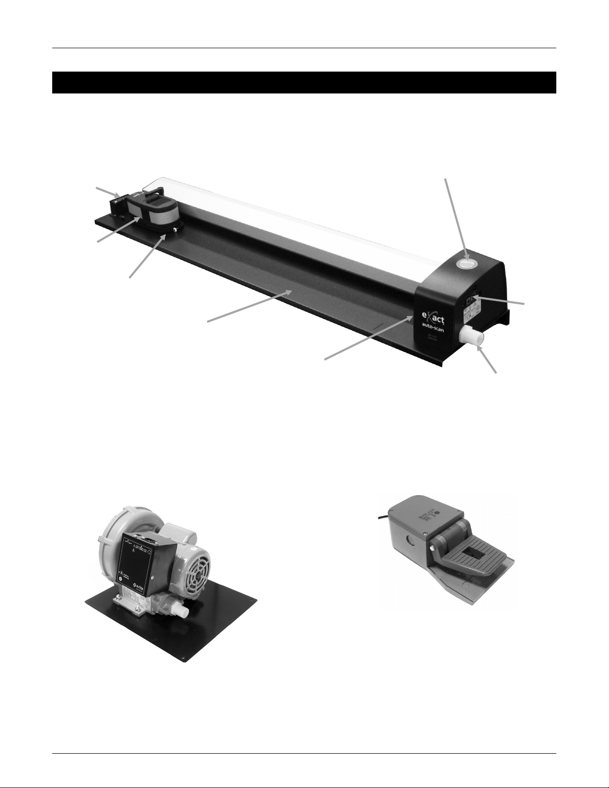
Operation button and Instrument Indicator
(surrounds operation button)
eXact instrument
not included)
USB, vacuum
pump
adapter
connection
location
Scanning track with
Vacuum connector
Laser location
eXact charging
Vacuum Pump (optional)
Scanning trolley
Foot Switch (optional)
Overview and Setup
The eXact Auto-Scan system provides fast, press-side color control. The instrument can also be detached
from the scanning trolley to allow you to take spot check measurements.
station
(
vacuum holes
and AC
s
A series of small holes located in the surface of the
track hold down the press sheet when the optional
vacuum pump is connected.
The optional foot switch provides “hands-free”
measurement activation.
About this manual
This manual covers the installation, basic operation and maintenance of the system. Specific instructions
4
for using the instrument with your software application can be found in the software online help.
Page 7
Unpacking and Inspection
• eXact Auto-Scan
• Handled paper stop (2)
• Charging Adapter
• Vacuum pump (optional)
• USB interface cable
• Foot switch (optional)
• AC adapter (X-Rite P/N SE30-277) and line cord
• eXact InkKeyControl 2 software (optional)
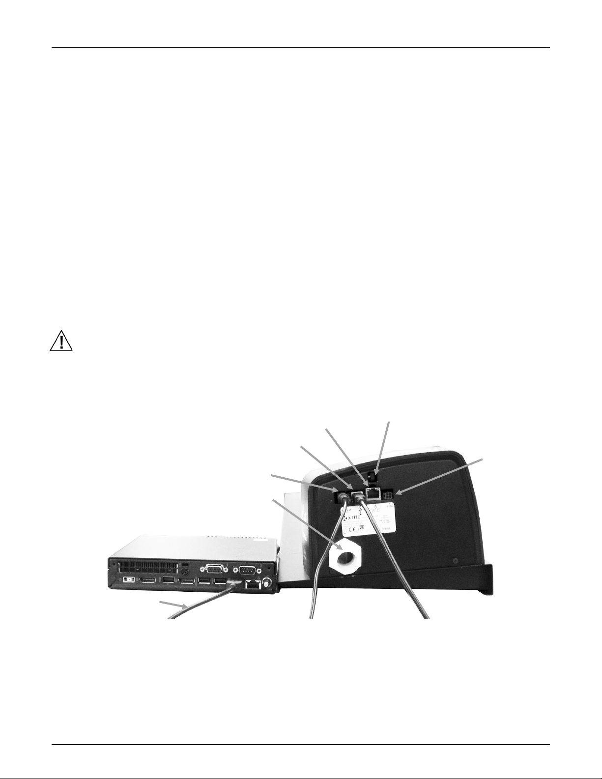
• Paper stop / flat hold down magnet (4)
Power supply (2)
USB port (1)
Optional vacuum pump hose connection
Optional vacuum
USB cable
Computer
Ethernet port (not used)
Laser alignment wheel (refer to the
After removing the instrument from the shipping carton, inspect it for damage. If any damage has
occurred during shipping, immediately contact the transportation company. Do not proceed with
installation until the carrier’s agent has inspected the damage.
Your instrument was packaged in a specially designed carton to assure against damage. If shipment is
necessary, the instrument should be packaged in the original carton along with all the accessories. If the
original carton is not available, contact X-Rite to have a replacement shipped to you.
Packaging Contents:
System Connections
Note: Please allow the system to stabilize at room temperature before plugging the power supply into
an AC wall receptacle.
Operational hazard exists if a power supply other than X-Rite SE30-277 is used.
1. Plug one end of the USB cable into the port on your computer.
2. Plug the other end of the cable into the USB port (1) on the right side of the system.
3. Plug the input connector from the eXact Auto-Scan power supply into the input port (2) located on
the right side of the system.
eXact Auto- Scan System
Appendix)
pump/foot switch
connection
4. Plug the detachable line cord into the power supply and then plug the line cord into the AC wall
receptacle.
5. Connect the computer power supply, monitor, keyboard and mouse (if applicable) to the computer
according to the instructions supplied with those devices.
NOTE: Refer to the following pages for information on connecting the optional vacuum pump and foot
switch if required.
5
Page 8
e X act Auto- S can Syste m
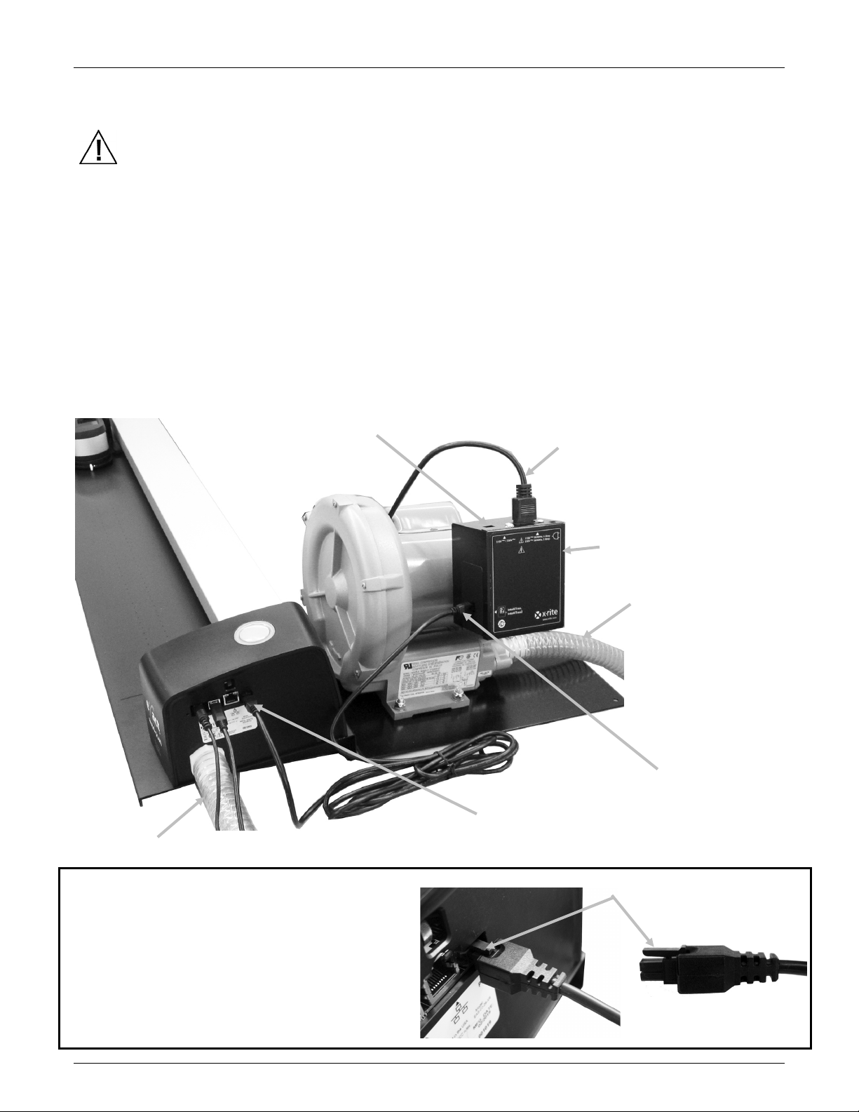
Vacuum hose (1)
Vacuum pump cable (2)
Control box (3)
Voltage selection
)
Line cord (5)
Vacuum pump cable (2)
Vacuum hose (1)
Connector clip
Connecting the Vacuum Pump Only (optional)
1. Connect one end of the vacuum hose (1) to the barbed input fitting located on the vacuum pump,
and the other end to the barbed fitting on the right side of the system.
2. Plug one end of the vacuum pump cable (2) into the connecter on the control box (3) and the other
end of the cable into the connector on the right side of the system.
IMPORTANT: Refer to the bottom of the page for the proper procedure to remove the vacuum
pump cable connectors from the eXact Auto-Scan and control box.
3. Make sure the voltage selection switch (4) on the top of the control box (3) is set to the proper line
voltage for your region.
4. Connect the detachable line cord (5) to the control box (3), and then plug the line cord into an easily
accessible, grounded AC wall receptacle. Note: Only use appropriately approved AC Line Cord that
X-Rite provides. Any other AC Line cord can compromise the integrity of regulatory agencies
approvals for this product. Please contact X-Rite for replacement of the AC Line cord suitable
maintaining this products compliance.
switch (4
Proper Vacuum Pump Cable Removal Procedure
1. Press downward on the clip at the top of the
2. Slowly pull cable connector outward.
6
cable connector.
Page 9

Connecting the Foot Switch and Vacuum Pump (optional)
Foot switch
cable
Foot switch cable (2)
Control
Voltage selection
Line cord (7)
Vacuum
(1)
Vacuum hose (1)
Foot Switch (3)
Connector clip
The foot switch option can only be used in conjunction with the optional vacuum pump.
1. Connect one end of the vacuum hose (1) to the barbed input fitting located on the vacuum pump,
and the other end to the barbed fitting on the right side of the system.
2. Plug one cable (2) from the foot switch (3) into the connector on the right side of the system.
3. Plug the other cable (4) from the foot switch (3) into the connector on the vacuum pump control
box (5).
IMPORTANT: Refer to the bottom of the page for the proper procedure to remove the foot switch
cable connectors from the eXact Auto-Scan and control box.
4. Make sure the voltage selection switch (6) on the top of the control box (4) is set to the proper line
voltage for your region.
5. Connect the detachable line cord (7) to the control box (5), and then plug the line cord into an easily
accessible, grounded AC wall receptacle. Note: Only use appropriately approved AC Line Cord that
X-Rite provides. Any other AC Line cord can compromise the integrity of regulatory agencies
approvals for this product. Please contact X-Rite for replacement of the AC Line cord suitable
maintaining this products compliance.
eXact Auto- Scan System
switch (6)
box (5)
(4)
hose
Proper Foot Switch Cable Removal Procedure
1. Press downward on the clip at the top of the
cable connector.
2. Slowly pull cable connector outward.
7
Page 10

e X act Auto- S can Syste m
Indicator light
Installing the eXact InkKeyControl 2 Software (Optional)
System Requirements
• 2 GHz computer processor, 3 GHz recommended
• 2 GB minimum, 4 GB recommended
• Windows 7, Windows 8, Windows 10
• 100 GB hard drive or higher
• 17” touch-screen monitor with 1280 x 1024 resolution minimum, 22” touch-screen monitor with
1920 x 1080 resolution recommended
Installing the Software
NOTE: Shut down the Windows firewall and any anti-virus software you may be running. If you are
reinstalling or updating the software, you must first uninstall the current version of eXact InkKeyControl
2 from your computer. This will not delete any of your stored database files. All information will be
retained.
The eXact InkKeyControl 2 software uses a standard Windows installation procedure.
1. Insert the eXact InkKeyControl 2 software flash drive into the USB port. If eXact InkKeyControl 2
setup screen does not open automatically, open Windows Explorer and browse to the USB drive
letter. Double-click the Setup.exe file.
2. The setup program guides you though the rest of the installation process. Follow the instructions on
each setup screen to complete the installation.
3. Refer to the eXact InkKeyControl 2 online help system for information on operation of the software.
NOTE: eXact InkKeyControl 2 uses a free version of SQL Server. This version is fully functional with a few
limitations. Please refer to the online help in the Database Administration Tool for more information.
eXact Auto-Scan Indicator
The indicator that surrounds the operation button illuminates system operation conditions.
Solid Green: indicates that the eXact instrument is docked at the charging station and ready for use.
Solid Orange: indicates that the instrument is taking a measurement.
8
Page 11

Setting Up the eXact Instrument
Charging
Target window (3)
Target base (2)
USB cable
1. Activate the Bluetooth function on your instrument and pair it with your computer. Refer to the
eXact User Guide for additional information.
2. Plug the charging adapter (1) into the back of the eXact instrument. The adapter is properly
attached when the tab on the bottom snaps into the security cable slot on the back.
To remove the charging adapter, push up on the locking tap and pull outward.
adapter (1)
eXact Auto- Scan System
NOTE: If the Bluetooth function is not used, route the USB for the
eXact instrument in the channel at the top of charging adapter.
This will help prevent the cable from interfering with the charging
station and track during operation. This USB cable is separate
from the eXact Auto-Scan system USB cable that was previously
installed. Plug the square end of the USB cable into the back of
the instrument. Plug the USB cable into an available port on your
computer.
3. Lock the eXact target base (2) against the instrument.
4. Flip the target window (3) back 180° on the bottom of the eXact target base.
9
Page 12

e X act Auto- S can Syste m
Scanning trolley (4)
Locking arm (6)
Charging station (5)
5. Move the scanning trolley (4) a few inches from the charging station (5).
6. Position the eXact instrument over the scanning trolley (4) and lower into place.
7. Secure the eXact to the scanning trolley by rotating the locking arm (6) counterclockwise until it
stops. This holds the instrument in place during scanning.
10
8. Slide the instrument and scanning trolley against the charging station (5).
Page 13

eXact Auto- Scan System
Charging station (5)
11
Page 14

e X act Auto- S can Syste m
White dash mark
Laser line
Operating the System
You should refer to the online help in the software application for procedures on creating and selecting
color bars. The following information is provided to familiarize you with the mechanical aspects required
when measuring.
Sheet Loading and Alignment
The press sheet can be loaded from the back and passed through the track or from the front to align the
color bar. The press sheet is held in place by the supplied magnets or series of vacuum holes if the
optional pump is used.
CAUTION: CLASS 1 LASER PRODUCT
1. If not already done, slide the instrument and scanning trolley against the charging station. This will
activate the alignment laser.
NOTE: Make sure the laser line is centered on the white dash mark at the end of the scanning trolley. If
the laser is not centered, you will need to align the laser before scanning. Refer to the Laser Alignment
Procedure in the Appendix.
12
2. Place the edge of the press sheet at the white line (1) in front of the scanning trolley.
3. Manually align the color bar so that the laser line (2) runs down the center of the color bar to be
measured.
NOTE: After 30 seconds, the laser line will turn off if a measurement is not started. To reactivate the
laser use one of the following methods:
• move the trolley away from the charging station and then return it back to the charging
station
• turn on the laser using the icon in the eXact InkKeyControl software
• press the Operation button on the eXact-Scan system
• use the optional foot switch if that is part of your configuration
4. If required, locate paper stop/flat hold down magnets (3) at the top edge of the press sheet to help
with the alignment of additional sheets. Refer to the next page for additional paper stop alignment
option.
Page 15

eXact Auto- Scan System
White line (1)
Laser line (2)
Paper stops (3)
Flat hold down
magnet (4)
Flat hold down
magnet (4)
Handled paper stop
5. For systems that do not use a vacuum pump: Position the paper stop/flat hold down magnets (4)
over the sheet along the bottom edge of the track.
Handled Paper Stop Option: You can
also position the handled paper stops
(5) along the bottom edge of the sheet
for alignment if your system is located
on a metal table/console.
magnets (5)
Measuring a Color Bar
The following instructions describe the procedures required to measure a color bar.
Caution: Moving parts – please keep hands clear when the scanning trolley is in motion.
1. Make sure the press sheet is properly aligned as previously explained.
2. Open a job from the software application.
3. Select the Measure option in the software or press the Operation button on the eXact Auto-Scan
system to start the measurement. You can also press the optional Foot switch to start a
measurement.
IMPORTANT:
The first press of the Operation button or Foot switch will turn on the laser. If the laser is already on,
the next press of the Operation button or Foot switch will start a measurement.
Once the measurement has been initiated, the laser turns off, the vacuum pump activates (if the
optional vacuum pump is used) and the “green” light on the eXact Auto-Scan system changes to
13
Page 16

e X act Auto- S can Syste m
Operation button
“solid orange”, indicating a scan is in progress. After the color bar is scanned, measurement results
are reported to the computer monitor.
You can abort a measurement by pressing the Operation button or optional Foot switch when the
instrument is scanning the color bar.
Performing a Spot Color Measurement
The instrument can be used to measure ink colors and make spot check measurements as needed. The
target base of the instrument should rest flat and steady on the sample area.
The following instructions describe the procedures required to perform a spot measurement with the
eXact instrument.
1. Remove the eXact instrument from the scanning trolley.
2. Flip the target window 180° on the bottom of the eXact target base back to the spot measurement
position.
3. Position the target window over the sample to measure. The opening should be completely filled
with the sample color.
4. Press the instrument firmly to the target base. Measuring appears in the display.
5. Hold steady until “Complete!” is displayed. Measurement results are reported to the computer
monitor.
14
6. If the instrument is moved during measurement or is not held closed for the entire measurement,
no data will display on the computer monitor. Simply take another measurement if this occurs.
Page 17

7. When finished, flip the target window back to the scan position and reattach the instrument to the
scanning trolley.
Calibration
IMPORTANT: The calibration plaque is dramatically affected by smudge marks and dust, and must be
kept clean. It is recommended that the instrument is cleaned regularly. Refer to the cleaning procedure
in the Appendix.
1. When prompted for a calibration, remove the eXact instrument from the scanning trolley if
required.
2. Open the instrument (not locked) and tap the START button on the eXact screen. The instrument
will display a countdown screen and then perform the calibration.
eXact Auto- Scan System
15
Page 18

e X act Auto- S can Syste m
Reset button location
Appendices
Service Information
The eXact Auto-Scan is covered by a one-year limited warranty and should be referred to an authorized
service center for repairs within the warranty period.
X-Rite provides repair service to their customers. Because of the complexity of the circuitry, all repairs
should be referred to an authorized service center.
X-Rite will repair any instrument past warranty. The customer shall pay shipping and repair cost to the
authorized service center. The instrument shall be submitted in the original carton, as a complete
unaltered unit along with all the supplied accessories.
Troubleshooting
Prior to contacting X-Rite’s Customer Service for instrument problems, try the applicable solution(s)
described below. If the condition persists, contact X-Rite Customer Service by phone at 1-888-826-3059;
by fax at 1-888-826-3061; or by email at gisupport@xrite.com. Additional X-Rite office numbers are
located on the back cover of this manual. You can also visit X-Rite’s Support page at www.xrite.com;
here you can find answers to common help desk questions.
Scanning instrument indicator not illuminating:
Ensure that the power supply is plugged in.
Reset the instrument (see eXact Auto-Scan Reset).
Scanning instrument and software not communicating:
Check the USB cable for proper connection.
Close the software application, cycle power on the instrument and restart the software application. If
this does not work reboot the computer.
Reset the instrument (see eXact Auto-Scan Reset).
eXact Auto-Scan Reset
16
The following procedure performs a hardware reset
on the eXact Auto-Scan system.
1. Make sure the system is powered on.
2. Using a small screwdriver or paperclip, press in
the reset button. The reset button is located in
the hole to the left of the power supply cable.
3. The indicator light will change to orange and
then back to green. Release the reset button
when indicator light is back to green.
Page 19

Cleaning the System
(1)
(2)
Your system requires very little preventative maintenance to achieve years of reliable operation.
However, to protect your investment and maintain reading accuracy, a few simple-cleaning procedures
should be performed from time to time.
ATTENTION: A properly grounded wrist strap is recommended when cleaning, removing or installing the
scanning head.
Make sure AC power is disconnected from the system before performing any instrument cleaning
procedure.
General eXact Auto-Scan Cleaning
The system covers may be wiped clean with a cloth dampened in water or mild cleaner.
DO NOT spray water or cleaning solution directly on the end covers or scanning track.
DO NOT use any solvents or harsh cleaners of any kind.
The track should be wiped clean with a lint-free cloth dampened in glass cleaner weekly or more often if
needed. When cleaning the track, make sure to clean the entire track. This includes the portion of the
track that resides under the eXact instrument trolley when it is in its docked position. You can slide it
over when cleaning is required.
eXact Auto- Scan System
System Contacts Cleaning
1. Remove the eXact instrument from the scanning trolley and power it off.
2. Turn the eXact instrument over and wipe the contacts on the charging adapter (1) weekly with a
cotton cloth dampened (not wet) in isopropyl alcohol.
3. Make sure power is disconnected from the eXact Auto-Scan system.
4. Wipe the contacts on the eXact charging station (2) weekly with a cotton cloth dampened (not wet)
in isopropyl alcohol.
17
Page 20

e X act Auto- S can Syste m
(1)
(2)
(1)
(2)
General eXact Cleaning
The exterior of the instrument and touch display should only be wiped clean with a cotton cloth
dampened (not wet) in water or isopropyl alcohol.
Cleaning the eXact Optics
The optics should be cleaned once a week in a normal environment. If the instrument is used in a dirty
or dusty environment, more frequent cleaning may be required.
1. Remove the instrument from the scanning trolley.
2. Rotate the reference holder (1) towards the back and hold.
3. Blow short bursts of clean, dry air (2) into the measurement port. This should remove any
accumulated debris from the optics.
4. Carefully return the calibration holder to its normal position.
IMPORTANT: If can air is used for cleaning, do not invert or tilt the can during use. This could cause
damage to the optics.
Cleaning the eXact Calibration Plaque
The calibration plaque should be cleaned periodically.
Do not use solvents or cleaners of any kind.
The calibration tile is embedded in the underside of the reference holder.
1. Remove the eXact instrument from the scanning trolley and open the target base.
2. Rotate the reference holder (1) towards the back and hold.
3. Blow short bursts of clean, dry air (2) onto the calibration tile. This should remove any accumulated
debris.
4. Carefully return the calibration holder to its normal position.
18
Page 21

Laser Alignment Procedure
The laser will require alignment if the laser line is not centered on the white dash mark at the end of the
scanning trolley. Follow the steps below for the proper alignment procedure.
1. Make sure the instrument and scanning trolley are pushed up against the charging station to
activate the laser line.
2. View the location of the laser line at the front of the scanning trolley.
Laser line not properly aligned
Incorrect back alignment Incorrect front alignment
eXact Auto- Scan System
3. If the laser line is to the back of the white dash mark, rotate the alignment wheel adjustment
upward to center the laser line on the white dash mark.
If the laser line is to the front of the white dash mark, rotate the alignment wheel adjustment
downward to center the laser line on the white dash mark.
Laser line adjustment wheel Laser line properly aligned
19
Page 22

e X act Auto- S can Syste m
Measurement System
Spectral Analyzer
DRS spectral engine
Spectral Range
400 nm – 700 nm with 10 nm interval
Measurement Geometry
45°/0° ring illumination optics, ISO 5-4:2009(E)
Light Source
Gas filled tungsten (illuminant type A) and UV LED
Measurement Conditions
M0, M1 (method 1 and method 2), M2, M3* (all according
*M3 option not available for Xp models
Calibration
On integrated white reference
Inter-instrument agreement
Average: 0.25 ∆E*ab, Max: 0.45 ΔE*ab (M3 0.55 ΔE*ab)
ceramic reference (D50, 2°))
Short term repeatability - White
0.05 ∆E*ab, (standard deviation) White BCRA
5 seconds)
Short term repeatability - Density
+/-0.01 D for CMYK measurements
Data Interface
Bluetooth
Scan System
Track Lengths
29”/74 cm, 40”/102 cm
Min. Patch Size (Strip Height)
3.0 mm (with 1.5 mm aperture)
4.0 mm (with 2 mm aperture)
Scan Speed
1.5 mm aperture on 4 mm patches: >= 160 mm (7”)/sec.
Data Port
USB, Ethernet
eXact InkKeyControl
Software
Colors
Up to 16 colors
Print Standard Support
G7, PSO, Japan Color ISO 12647-2
Density Functions
Density, TVI (incl. SCTV), Trapping, Contrast, Gray Balance
Colorimetric Functions
CIE L*a*b*, CIE L*C*h°
dE methods
dE*76, dE*94, dE*00
Special Functions
BestMatch
Density White Base
Absolute, Paper
Pantone Color Libraries
Included
PantoneLIVE Support
Optional
Environmental
Operating Temp:
+10° (50°F) to +35°C (95°F)
Humidity Range:
0 - 85% RH non-condensing
Storage Temp:
-20°C to +50°C
Usage:
Indoor only
Altitude:
2000m
Pollution Degree:
2 Overvoltage:
Category II
Power Supply:
X-Rite P/N SE30-277, 100-240VAC 50/60Hz, 12VDC @ 2.5A
Vacuum Pump:
X-Rite P/N: SD07-07, 115/230 VAC 60/50 HZ 3.6/1.8 AMPS
Design and specifications subject to change without notice.
eXact Auto-Scan Specifications
to ISO 13655:2009)
(Measurements using X-Rite manufacturing standards at a
temperature of 23°C +/- 1°C, 40-60% RH for all
measurement modes on 12 BCRA color tiles and a white
(Error compared to mean value of 10 measurements every
20
Page 23
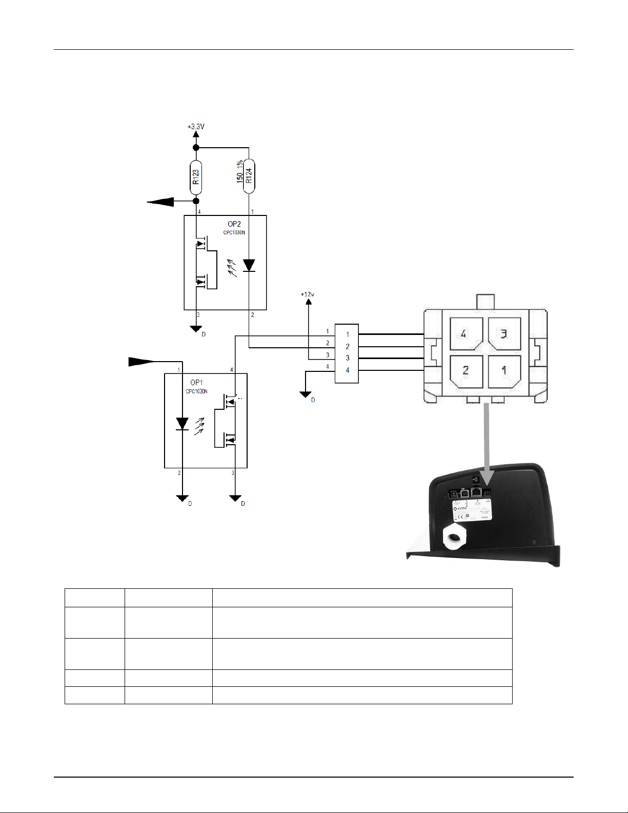
eXact Auto-Scan Vacuum/Foot Switch Interface Wiring
Pin
Name
Description
1
Output
External Control Line: provides up to 120mA current sink
2
Input
External Trigger Line: turns on laser when pulled to ground, if
3
+12v
Provides +12 VDC, up to 500mA (not fused).
4
GND
DC Ground
INPUT
OUTPUT
The CPC1030 has a maximum
eXact Auto- Scan System
current of 120mA.
during measurement sequence.
laser is already on a measurement will begin.
21
Page 24

Corporate Headquarters
X-Rite, Incorporated
4300 44th Street SE
Grand Rapids, Michigan 49512
Phone 1 800 248 9748 or 1 616 803 2100
Fax 1 800 292 4437 or 1 616 803 2705
European Headquarters
X-Rite Europe GmbH
Althardstrasse 70
8105 Regensdorf
Switzerland
Phone (+41) 44 842 24 00
Fax (+41) 44 842 22 22
Asia Pacific Headquarters
X-Rite Asia Pacific Limited
Suite 2801, 28th Floor, AXA Tower
Landmark East, 100 How Ming Street
Kwun Tong, Kowloon, Hong Kong
Phone (852) 2568 6283
Fax (852) 2885 8610
Please visit www.xrite.com
for a local office near you.
P/N EASEN-500 Rev. B
 Loading...