

Page 1

ATD
AUTO-TRACKING DENSITOMETER
Scanning Instrument Manual
(covers ATD Sheet and ATD News Systems)
Page 2

Page 3

I N T R O D U C T I O N
User Information
FCC
This equipment has been tested and found to comply with the limits for a Class A
digital device, pursuant to Part 15 of the FCC Rules. These limits are designed to
provide reasonable protection against harmful interference when the equipment is
operated in a commercial environment. This equipment generates, uses, and can
radiate radio frequency energy and, if not installed and used in accordance with the
instruction manual, may cause harmful interference to radio communications.
Operation of this equipment in a residential area is likely to cause harmful
interference in which case the user will be required to correct the interference at his
own expense.
NOTE: Shielded interface cables must be used in order to maintain compliance with
the desired FCC and European emission requirements.
Canada
This Class A digital apparatus meets all requirements of the Canadian InterferenceCausing Equipment Regulations.
Cet appareil numérique de la classe A respecte toutes les exigences du Règlement
sur le matériel brouilleur du Canada.
AVERTISSEMENT : Des câbles d'interface blindés doivent être utilisés afin de se
conformer aux règlements européens et FCC (USA)sur l'émission
Keep Cal Plaques Clean At All Times.
Kalibrierstandard stets sauber halten!
Siempre mantenga la placa de calibración limpia.
Tenir le plaque de calibration propre tout le temps.
Sempre mantenga la placca della calibrazione pulita.
Do Not Oil Moving Parts.
Bewegliche Teile nicht ölen!
No lubrifique las peizas en movimiento
Ne pas lubrifier les pièces en mouvement
Non lubrificare le parti mobili.
i
Page 4

CAUTION: Use only the 24v Adapter (P/N ATS40-109) to supply power to the
Docking Station.
VORSICHT: Benutzen Sie nur den X-Rite- 24V-AC-Adapter (P/N SE30-75) als
Stromanschluß zur Kopplerstation.
ADVERTENCIA: Use solamente el Adaptador de 24v (pieza Nº ATS40-109) para
suministrar la energía al mecanismo de conexión.
AVERTISSEMENT: Utiliser seulement l’adaptateur de 24v (P/N ATS40-109) pour
fournir l’alimentation au mécanisme de connexion.
AVVERTIMENTO: Usare solamente l’adattatore di 24v (parte n. ATS40-109) per
fornire l’alimentazione al meccanismo del collegamento.
The Manufacturer: X-Rite, Incorporated
Der Hersteller: 4300 44th Street, S.E.
El fabricante: Grand Rapids, Michigan 49512
Le fabricant:
Il fabbricante:
Declares that: Auto Tracking Densitometer
gibt bekannt: ATD
advierte que:
avertit que:
avverte che:
is not intended to be connected to a public telecommunications network.
an ein öffentliches Telekommunikations-Netzwerk nicht angeschlossen werden soll.
no debe ser conectado a redes de telecomunicaciones públicas.
ne doit pas être relié à un réseau de télécommunication publique.
non deve essere connettuto a reti di telecomunicazioni pubblici.
ii
CE DECLARATION
Manufacturer's Name: X-Rite, Incorporated
Manufacturer's Address: 4300 44
Grand Rapids, Michigan 49512 U.S.A.
Model Name: Auto Tracking Densitometer
Model No.: ATD
Directive(s) Conformance: EMC 89/336/EEC LVD 73/23/EEC
WEEE
As of August 13, 2005, X-Rite products meet the European Union – Waste
Electrical and Electronic Equipment (WEEE) directive. Please refer to
www.xrite.com
WEEE directive.
for more information on X-Rite’s compliance with the
th
Street, S.E.
Page 5

PROPRIETARY NOTICE
The information contained in this manual is derived from patent and
proprietary data of X-Rite, Incorporated. This manual has been prepared
solely for the purpose of assisting in the use and general maintenance of
this instrument.
Any reproduction in whole or part is strictly prohibited. Publication of this
information does not imply any rights to reproduce or use this manual for
purposes other than installing, operating, or maintaining this instrument. No
part of this manual may be reproduced, transcribed, transmitted, stored in a
retrieval system, or translated into any language or computer language, in
any form or by any means, electronic, magnetic, mechanical, optical,
manual, or otherwise, without the prior written permission of an officer of
X-Rite, Incorporated.
This instrument may be covered by one or more patents. Refer to the
instrument for actual patent numbers.
Copyright © 2007 by X-Rite, Incorporated
“ALL RIGHTS RESERVED”
I N T R O D U C T I O N
X-Rite® is a registered trademark of X-Rite, Incorporated
All other logos, product names, and trademarks mentioned are the property of their respective holders.
iii
Page 6

LIMITED WARRANTY
X-Rite, Incorporated (“X-Rite”) warrants each instrument manufactured to
be free of defects in material and workmanship (excluding battery pack) for
a period of 36 months. This warranty shall be fulfilled by the repair or
replacement, at the option of X-Rite, of any part or parts, free of charge
including labor, F.O.B. its factory or authorized service center.
This warranty shall be voided by any repair, alteration, or modification, by
persons other than employees of X-Rite, or those expressly authorized by
X-Rite to perform repairs, and by any abuse, misuse, or neglect of the
product, or by use not in accordance with X-Rite’s published instructions.
X-Rite reserves the right to make changes in design and /or improvements
to its products without any obligation to include these changes in any
products previously manufactured. Correction of defects by repair or
replacement shall constitute fulfillment of all warranty obligations on the
part of X-Rite.
THIS WARRANTY IS EXPLICITLY IN LIEU OF ANY OTHER
EXPRESSED OR IMPLIED WARRANTIES, INCLUDING ANY
IMPLIED WARRANTY OF MERCHANTABILITY OR FITNESS FOR
ANY PARTICULAR PURPOSE. THIS WARRANTY OBLIGATION IS
LIMITED TO REPAIR OR REPLACEMENT OF THE UNIT
RETURNED TO X-RITE OR AN AUTHORIZED SERVICE CENTER
FOR THAT PURPOSE.
This agreement shall be interpreted in accordance with the laws of the State
of Michigan and jurisdiction and venue shall lie with the courts of
Michigan as selected by X-Rite, Incorporated.
iv
Always include serial number in any correspondence concerning the unit.
Serial numbers are located on the bottom of the scanning head and right end
plate of the track.
Page 7

INSTRUMENT TRACEABILITY
The spectral reflectance values for the supplied white reference are
traceable to the National Institute of Standards and Technology through the
RIT Munsell Color Laboratory. The RIT Laboratory maintains standards to
which NIST assigned values. These standards were used in assigning values
to X-Rite’s two primary standard white porcelain on steel plaques.
A calibration report (MCSL-18) issued by Munsell Color Science
Laboratory contains measurement methods, measurement values, and
verifies the ceramic plaques’ NIST traceability path. These two plaques are
used to generate the supplied white reference.
ABOUT THIS MANUAL
This document covers the installation, operation, calibration and general
maintenance of your instrument. Refer to your software documentation and
on-line help for complete software installation and operation instructio ns.
This manual is organized into four sections and two appendices. In order to
make the best use of your system, it is recommended that you read all
sections and appendices.
I N T R O D U C T I O N
v
Page 8

I N T R O D U C T I O N
Table of Contents
SECTION ONE—Installing the System
Unpacking and Inspection..........................................................1-1
Packaging Drawing and Parts List.......................................1-1
System Description..................................................................... 1-2
Track and Docking Station................................................... 1-3
Scanning Head .................................................................... 1-4
Vacuum Pump......................................................................1-4
Reattaching the Scanning Head................................................. 1-5
System Connections...................................................................1-6
Vacuum Pump Connections ................................................1-6
RS-232 Interface Connection .............................................. 1-8
Connecting Power................................................................ 1-9
SECTION TWO—Operating the System
Calibrating the Scanning Instrument.......................................... 2-2
Sheet Loading and Alignment.................................................... 2-3
Standard Track Positioning.................................................. 2-3
Feed-Through Track Positioning ......................................... 2-4
Taking a Measurement with the ATD Sheet Instrument ............2-5
Taking a Measurement with the ATD News Instrument............. 2-6
vi
SECTION THREE—General Maintenance
Repair Information...................................................................... 3-1
Overview..................................................................................... 3-1
Scanning Head........................................................................... 3-1
Cleaning............................................................................... 3-2
Maintenance......................................................................... 3-3
Scanning Track........................................................................... 3-3
Cleaning............................................................................... 3-3
Maintenance......................................................................... 3-3
Cleaning the Scanning Instrument Calibration Disks................. 3-4
SECTION FOUR—Troubleshooting Tips .................4-1
APPENDIX A—Technical Specifications................A-1
APPENDIX B—Parts List and
Packaging Drawing
.........................................................B-1
Page 9

S E C T I O N O N E
Installing the System
This section covers unpacking, inspection, and installation of your system.
System description and vocabulary illustrations are also included. You
should read through this entire section to familiarize yourself with your
instrument.
Section Contents
• Unpacking and Inspection................ 1-1
• System Description.......................... 1-2
• Reattaching the Scanning Head...... 1-5
• System Connections........................ 1-6
UNPACKING AND INSPECTION
The main system components are packaged separately:
• Track/Docking Station, Scanning Head, Cabling, Software,
Documentation, and Accessories
• Vacuum Pump
After removing the components from each shipping carton, inspect them for
damage. If any damage has occurred during shipping, immediately contact
the transportation company that shipped them. Do not proceed with
installation until the carrier’s agent has inspected the damage.
Your components were packaged in specially-designed cartons to help
prevent damage. If reshipment is necessary, the components should be
packaged in the original carton. If the original carton is not available,
contact X-Rite to have replacements shipped to you.
Packaging Drawings and Parts Lists
Check your package contents against your packing list and original order. A
detailed packaging drawing and parts list is included in this manual as
Appendix B.
1-1
Page 10

S E C T I O N O N E
SYSTEM DESCRIPTION
The ATD Sheet instrument provides density measurements while
automatically locates and center itself on a color bar that is within 38mm of
the paper’s edge.
The ATD News instrument scans news print gray balance rules or
continuous color mastheads that are manually aligned to the track LED’s.
Docking Station
Indicator Lamp
Operation Button
Scanning Head
Scanning Track
1-2
Page 11
I N S T A L L I N G T H E S Y S T E M
Track and Docking Station
The press sheet or news paper is held securely to the track with a series of
vacuum holes while the Scanning Head measures. The Operation button is
used to activate a measurement sequence.
The indicator light on the Docking Station illuminates three separate colo rs
for varies mode conditions:
• Solid Green Light—indicates that the scanning head is docked and
ready for use.
• Solid Yellow Light— indicates that the scanning head is away from
the docking station.
• Solid Red Light— indicates that an error or problem exists with the
system.
• Flashing Yellow Light—indicates unit powered up to take reading.
• Flashing Red Light—indicates there is a problem and unit needs
service.
• Flashing Yellow & Green—indicates system needs to be reset.
Pressing and holding Operation button for 5-seconds performs reset.
Operation Button
Indicator Lamp
Scanning Head Contact
Vacuum Holes
System Connections
1-3
Page 12
S E C T I O N O N E
V
Scanning Head
The ATD Sheet scanning head scans a color bar at a rate of 100mm a
second using a 4.5mm color patch size.
The ATD News scanning head scans a gray balance rule or continuous
color bar at a rate of 8in./sec. The head take approximately five
measurements per inch and averages all the reading across the user-defined
zone.
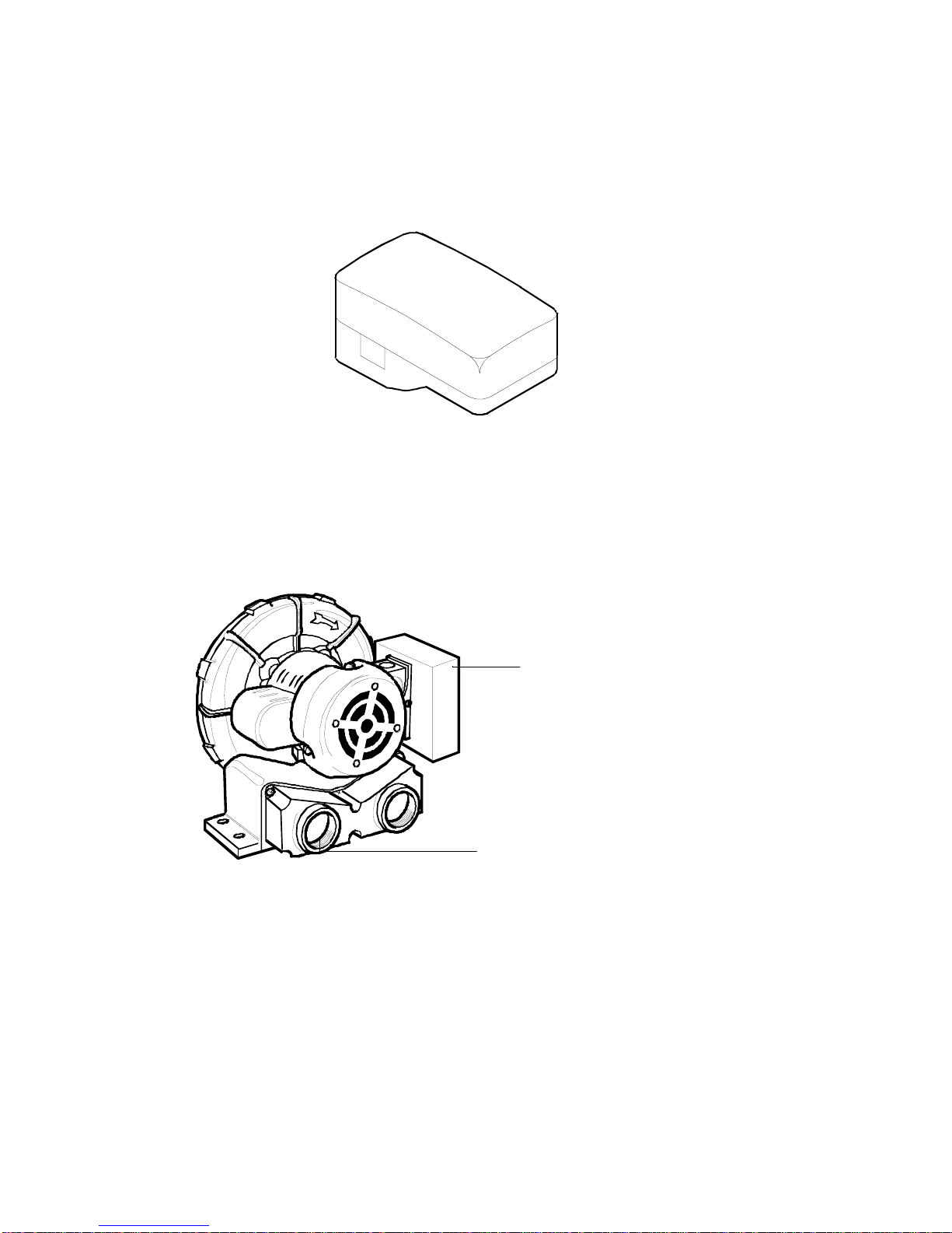
Vacuum Pump
A series of small holes located in the surface of the Track are used to hold
the press sheet in place during a measurement. This is accomplished by the
use of a Vacuum Pump. The Vacuum Pump is connected to the Docking
Station allowing automatic activation during a measurement cycle.
Interconnect Box
acuum Inlet Port
1-4
Page 13

I N S T A L L I N G T H E S Y S T E M
REATTACHING THE SCANNING HEAD
In the event that the scanning head is removed, follow the procedure below
to reattach it to the Trolley.
1. Position the Scanning Head Trolley approximately 12 inches from the
Docking Station. This is accomplished by sliding the Trolley away
from the Docking Station with your hand.
2. Position the Scanning Head over the Trolley and slide forward
allowing the Holding Disks to insert into the Scanning Head.
3. Align the Mounting Plate Thumbscrews with the Posts and Post Holes
in the Scanning Head.
4. Loosely secure the thumbscrews to the Scanning Head. Alternately
tighten until firmly seated.
NOTE: Scanning Head must be securely fastened to Trolley to allow
proper operation of instrument.
Scanning Head
Holding Disks
Head Connector
Docking Station
Thumbscrew
Posts
Post Hole
Trolley
1-5
Page 14

S E C T I O N O N E
V
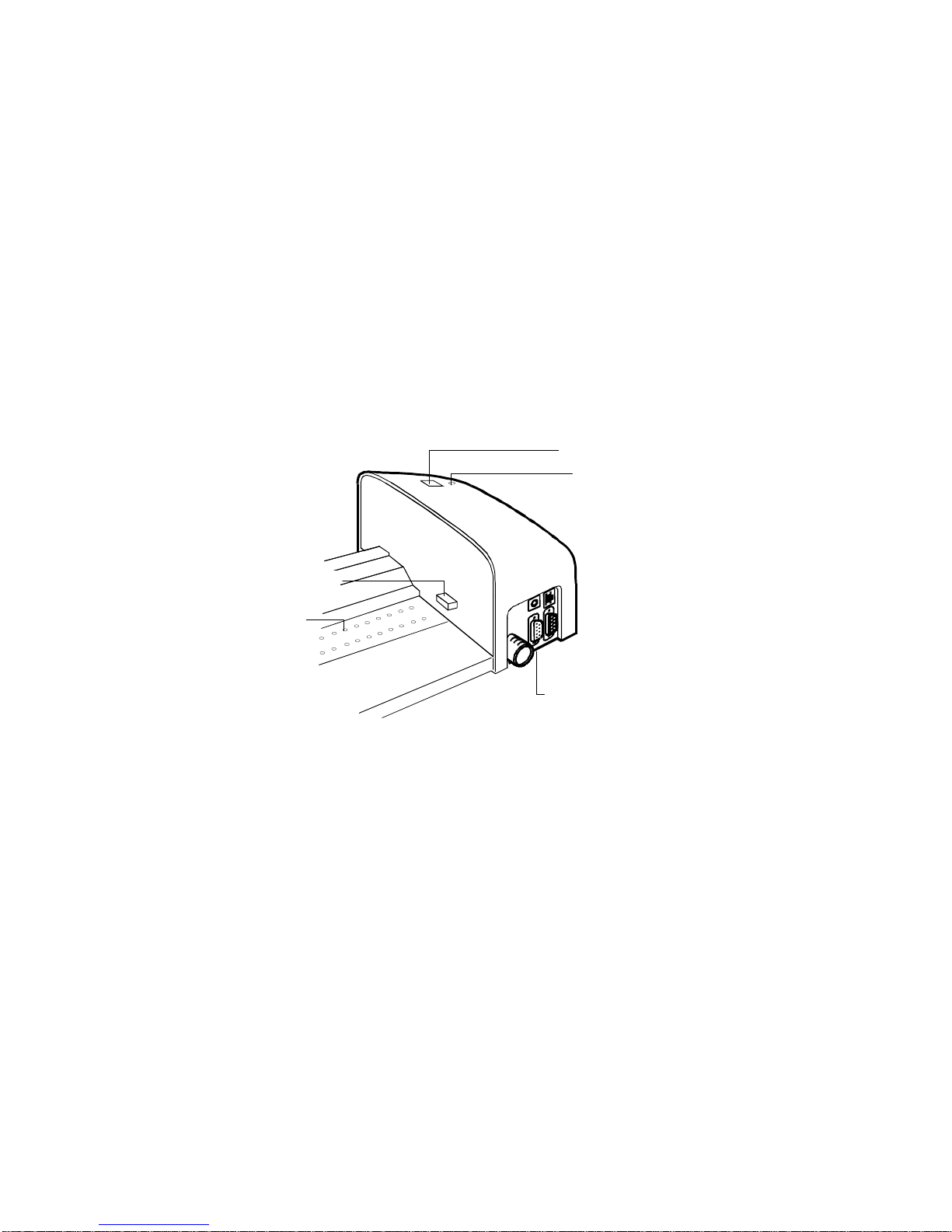
SYSTEM CONNECTIONS
The System requires a few simple connections before operating. Connection
procedures for the individual components are covered on the following pages.
Back of Docking Station
Power Input
Vacuum Pump I/O Port
Computer I/O Port
Vacuum
Pump Hose
Connection
Vacuum Pump Connections
1. Push one end of Vacuum Hose onto the Barbed Adapter at back of the
Docking Station.
1-6
2. Push other end of Vacuum Hose onto the Barbed Adapter on Vacuum
Pump.
NOTE: To obtain up to 15% more vacuum from the pump, remove the
exhaust port barbed adapter.
Docking Station
N
I
acuum Hose
Exhaust Port
OUT
Page 15

I N S T A L L I N G T H E S Y S T E M
3. Make sure the Voltage Selection Switch—located below Line Cord
Receptacle—has been set to the proper line voltage for your region.
4. Connect one end of I/O Interface Cable to the Vacuum Pump I/O Port
on the Docking Station.
5. Connect other end of I/O Interface Cable to an I/O Port on the Vacuum
Pump Connect Box (either port can be used).
6. Connect the Line Cord to the Vacuum Pump AC Cord Receptacle.
7. Plug Line Cord into AC wall receptacle.
NOTE: Vacuum Pump only operates during a measurement sequence.
Vacuum Pump I/O Port
I/O Interface Cable
I/O Port
Vacuum Pump
Connect Box
To AC Wall
Receptacle
Line Cord
Voltage Selection Switch
AC Cord Receptacle
1-7
Page 16

S E C T I O N O N E
RS-232 Interface Connection
1. Connect one end of the DB-9 Interface Cable to an available Serial
Port on back of your computer. Secure with thumbscrews.
2. Connect opposite end of DB-9 Interface Cable to Serial I/O Port on
back of Docking Station. Secure with Thumbscrews.
Serial I/O Port
Computer Serial
I/O Port
Thumbscrews
DB-9 Interface
Cable
Thumbscrews
1-8
Page 17

I N S T A L L I N G T H E S Y S T E M
Connecting Power
The system must be allowed to stabilize at room temperature before
plugging the adapter into an AC wall receptacle.
CAUTION: Use only the 24v Adapter (P/N ATS40-109) to supply
power to the Docking Station.
Power is applied to the Scanning System when the 24v Adapter is plugged
into an AC wall receptacle. The System does not have an ON/OFF switch.
NOTE: Scanning Head must be attached before power is applied.
1. Insert the adapter jack of the 24v Adapter into the Power Input on back
of Docking Station.
2. Insert the Detachable Line Cord into the socket on the 24v Adapter.
3. Plug the three-prong plug from the Line Cord into an AC Wall
Receptacle.
Detachable Line Cord
Power Input
24v Adapter Jack
24v Adapter
1-9
Page 18

S E C T I O N O N E
1-10
Page 19

S E C T I O N T W O
Operating the System
Now that you have made all the necessary connections (and loaded your
software) you are ready to operate your system. The heart of the Scanning
Instrument is the compact, scanning head. The ATD Sheet head moves along
the track at approximately 150mm/sec. The ATD News head moves along
the track at approximately 8in./sec. After a measurement, the scanning head
uploads the data to the computer via RS-232 communications.
This section covers instrument calibration, sheet loading and alignment, and
measurement procedures.
Refer to your software documentation or on-line help for information
regarding software operation.
Section Contents
• Calibrating the Scanning
Instrument........................................ 2-2
• Sheet Loading and Alignment.......... 2-3
• Taking a Measurement
with the ATD Sheet Instrument........ 2-5
• Taking a Measurement
with the ATD News Instrument ........ 2-6
2-1
Page 20

S E C T I O N T W O
CALIBRATING THE SCANNING INSTRUMENT
Calibrating the Scanning Instrument is virtually automatic, there is no
calibration reference to position. The Calibration References are a
permanent part of the Track assembly—located near the Docking Station.
The references are covered by a retractable cover when the Scanning Head
is away from the Docking Station, and exposed when the scanning head is
next to the docking station.
The Scanning Head automatically calibrates to the references when required
or when you request it.
Retractable Cover
2-2
NOTE: The calibration references should be cleaned periodically to
maintain calibration accuracy. Refer to Section Three, General Cleaning for
procedure.
Page 21

O P E R A T I N G T H E S Y S T E M
V
SHEET LOADING AND ALIGNMENT
Loading a press sheet or paper onto the Scanning Instrument is fast and
easy. There are no guides or clamps to adjust. The press sheet or paper is
loaded onto the track from the back over the plate that contains the vacuum
holes and LED’s (if a feed-through track). A vacuum is created once a
measurement sequence is started, holding the press sheet or paper in place.
The sheet or paper should be placed 90mm away from the docking station
or centered on the track, and at least 60mm away from the end of the track.
Standard Track Positioning
The press sheet must be positioned against the “sheet stops” that run along
the back edge of the vacuum plate. The color bar on the sheet cannot be
over 38mm from the paper’s edge.
In the event that a color bar is not properly aligned on a press sheet (this is
recognized during a job setup), the scanning system takes corrective action
by automatically adjusting the ATD scanning head. This ensures all color
patches are measured accurately even when a color bar is slightly skewed.
Press sheet should
Sheet Stops
not be positioned
directly under the
scan head.
A sheet alignment mark is located
in the center of the track.
acuum Holes
Color bar can be
38mm maximum
from paper edge
Press Sheet
Scanning
Track
2-3
Page 22

S E C T I O N T W O
V
Feed-Through Track Positioning
The feed-though track allows measurements at any location within the
paper. This is possible because the track has a slotted opening, allowing the
paper to be slide through the track.
The gray balance bar or color masthead bar is easily position on the track
using a series of LED’s that illuminate from the track through the paper.
The LED’s are located between the vacuum holes approximately every 5
inches along the track. Open the paper and position it so the LED’s are
shining down the center of the bar. The LED’s automatically shut off once
the scanning head starts in motion.
Bar position
acuum Holes
Newspaper
LED’s illuminate
through the
newspaper
2-4
Page 23

O P E R A T I N G T H E S Y S T E M
TAKING A MEASUREMENT WITH THE ATD SHEET
INSTRUMENT
After the press sheet is properly positioned on the track, you are ready to
perform a color bar recognition/measurement. The sequence is started in
one of two ways: by selecting the recognition/measurement function from
the Software, or by pressing the Operation button located on top of the
Docking Station.
Once a scan is set in motion, the vacuum pump activates and the “green”
light on the station changes to “yellow,” indicating a scan is in progress.
The scan head travels the entire length of the track before returning to the
docking station. If additional color bars are located on the opposite edge,
you will need to change sides. The software informs you when this is
required. Refer to your software documentation for additional information.
If a problem is encountered during a measurement, the scanning head
immediately returns to the docking station. View your computer monitor to
see if an error message is displayed. If no message is displayed, try to
rescan sheet; if a problem still occurs, refer to the Troubleshooting section
in this manual.
*Operation Button Activation
* Pressing the Operation Button
once during a scan aborts the scan
procedure. *Pressing and holding
the Operation button for five
seconds resets the System.
2-5
Page 24

S E C T I O N T W O
TAKING A MEASUREMENT WITH THE ATD NEWS
INSTRUMENT
After the newspaper is properly positioned on the track, you are ready to
perform a measurement. Press the Operation button located on top of the
Docking Station once to activate the vacuum pump. Then, press the button
again to start the measurement sequence.
Once a scan is set in motion, the “green” light on the station changes to
“yellow,” indicating a scan is in progress. The scan head travels the entire
length of the paper before returning to the docking station. Refer to your
software on-line help for specific information on the software operation.
If a problem is encountered during a measurement, the scanning head
immediately returns to the docking station. View your computer monitor to
see if an error message is displayed. If no message is displayed, try to
rescan the paper; if a problem still occurs, refer to the Troubleshooting
section in this manual.
*Operation Button
2-6
Page 25

S E C T I O N T H R E E
General Maintenance
This section will cover the maintenance procedures for the system.
Section Contents
• Repair Information ........................... 3-1
• Overview .......................................... 3-1
• Scanning Head ................................ 3-1
• Scanning Track................................ 3-3
• Cleaning the Calibration Disks......... 3-4
REPAIR INFORMATION
Your ATD System is covered by a three-year limited warranty and should
be referred to the factory for repairs within the warranty period. Attempts to
make repairs within this time frame may void the warranty.
X-Rite provides a factory repair service to their customers. Because of the
complexity of the circuitry, all repairs should be referred to the factory.
X-Rite will repair any ATD System past warranty. Shipping cost to the
factory shall be paid by the customer, and the instrument shall be submitted
in the original carton as a complete, unaltered unit.
OVERVIEW
The System requires little preventative maintenance to achieve years of reliable
operation. However, to protect your investment and maintain measurement
accuracy, a few simple cleaning procedures should be performed.
SCANNING HEAD
NOTE: DO NOT use any solvents or harsh cleaners of any kind.
NOTE: DO NOT move the trolley up and down the track manually without
the scanning head attached.
In the course of normal use, spray powder, paper dust, and other airborne
contaminants will likely enter the instrument's optics. This can eventually
reduce the sensitivity of the instrument and may lead to calibration errors.
Follow the steps below to clean the optical components.
3-1
Page 26

S E C T I O N T H R E E
Cleaning (1 to 2 times a month)
1. Obtain a source of clean, dry, compressed air. This air should be of the
2. Remove the scanning head from the track. To do this:
3. Being careful to hold the compressed air source upright, blow short,
quality used to clean delicate camera lenses.
- Disconnect power from the track.
- Gently slide the head away from the docking station.
- Loosen the two thumbscrews that lock the head to its trolley.
- Gently free the head from the trolley.
gentle bursts of compressed air directly into the instrument's aperture.
Be careful to ensure the compressed air nozzle is approximately 10mm
away from the optics.
3-2
4. Re-attach the scanning head to the trolley. To do this:
- Carefully align the head back onto the trolley. Take care to ensure
that the head is properly seated on the alignment pins.
- Tighten the thumbscrews that secure the head to the trolley. Gently
wiggle the head as you tighten the screws to ensure that the head is
fully seated.
- Slowly slide the head back into the docking station.
- Re-connect the power to the track.
Page 27

G E N E R A L M A I N T E N A N C E
5. Note that the process of cleaning the optics will affect the instrument's
sensitivity as dust and powder will no longer block the optical path. It is
essential that the head be fully calibrated following the cleaning process.
6. The exterior of the scanning head and docking station can be wiped
clean with a lint-free cloth dampened in water or a mild cleaner.
Maintenance
1. Replace the five (5) Read Head Pogos if they display any signs of
wear or discoloration.
2. On newer read heads, replace the Paper Stop Push Plate if anodize is
broke or worn through.
SCANNING TRACK
NOTE: DO NOT reverse the intake/exhaust port on the vacuum to blow
out the track vacuum chamber. This will force any dust inside the track into
the read head optics.
NOTE: DO NOT use any solvents or harsh cleaners of any kind.
NOTE: DO NOT use any type of lubrication (oil) on any part of the system.
Cleaning (1 to 2 time a month)
1. The exterior of the docking station can be wiped clean with a lint-free
cloth dampened in water or a mild cleaner.
2. The track can be wiped clean with a lint-free cloth dampened in glass
cleaner. When cleaning the track, make sure to clean the entire track.
This includes the portion of the track that resides under the reading
head when it is in its docked position. You can simply slide the head
over when cleaning is required.
3. Inside of track assembly – use compressed air to remove all print dust.
Maintenance
- Replace the following items at 500,000 scans.
- Trolley bearings and wheels
- Power cable
- End plate bearings (both ends)
- Nut on drive screw
- Station home sensor pogos
Usage Approximation
Usage Scans per day Year to reach 500,000
Heavy 300 4.5
Medium 150 9.0
Light 75 13.5
3-3
Page 28

S E C T I O N T H R E E
CLEANING THE SCANNING CALIBRATION DISKS
On a daily basis you may need to clean the Calibration Disks located in the
Track. This is a relatively easy procedure requiring only a few minutes of
time.
1. Carefully slide the Scanning Head away from the Docking Station.
2. Pull Calibration Cover towards the Docking Station to expose the
3. Clean Disks with a cotton swab or lint-free cloth.
4. Blow off Disks with compressed air.
5. Blow out under the Calibration Cover with compressed air.
4. Carefully release Calibration Cover and slide Scanning Head back
Calibration Cover
Disks.
against Docking Station.
Cotton Swab
3-4
Black Cal Disk
White Cal Disk
Docking Station
Scanning Head
Page 29

S E C T I O N F O U R
Troubleshooting Tips
The Software constantly scans the system looking for any type of problems
that may arise. When a problem is discovered, the Software displays an
error message on the computer monitor, pinpointing the problem area. A list
of “hardware” related error messages are listed below.
Error Messages and Reason/Solution
Error Messages Reason/Solution
Docking Failure
Lamp Burned Out
Lamp Intensity Low
Lamp Voltage High
Lamp Voltage Low
Motor Jammed
Motor Too Fast
Scanning Head not
at Docking Station
Measurement was initiated—scanning
head returned and docked—but the data
was not transmitted from the scanning
head. Check for loose cabling.
Scanning head needs service. Contact
X-Rite, Incorporated.
Measurement was initiated but the
scanning head was not at the docking
station. Slide head against docking
station.
4-1
Page 30

S E C T I O N F O U R
Other problems that may occur and not be detected by Software are as
follows.
Problems and Reason/Solution
Problems
Reason/Solution
Scanning head will not
activate when the
Software performs a
measurement cycle.
Measurements
incorrect or not
repeatable.
Check to see if Software displayed any
error message.
Check for proper connection of interface
cables and adapters between computer
and Scanning System.
Scanning System needs calibration.
Scanning head need service. Contract
X-Rite, Incorporated.
4-2
Page 31

A P P E N D I X A
Technical Specifications
ATD SHEET INSTRUMENT
Measurement Geometry 45°/0° per ANSI PH2.17
Light Source Gas Pressure @ 2850°K
Color Response Status T or Status E
Density Range 0 - 2.5D
Repeatability on White ±0.01 Density max.
Density Reproducibility ±0.02 Density @ 1.5 Density
Calibration Automatic
Patch Width
Patch Height Large Spot - 5.0mm min.
Medium Spot - 3.2mm min.
Small Spot - 1.6mm min.
Paper Thickness 1.5mm max.
Scanning Rate 150mm/sec. (6.8 mm patch)
Color Bar Location Paper Edge to 38mm from edge.
Color Bar Alignment Automatic centering of measurement on
color bar. Paper set against stop.
Color Bar Quantity Multiple Rows
Paper Hold Down Vacuum activated with measurement
command.
Power Required Station
Specifications and design subject to change without notice.
(along scan path) 3.8mm min.
110/240 VAC, 50-60Hz, 4/2A
Pump
115/230 VAC, 50-60Hz, 4/2A
A-1
Page 32

A P P E N D I X A
ATD NEWS INSTRUMENT
Measurement Geometry 45°/0° per ANSI PH2.17
Light Source Gas Pressure @ 2850°K
Color Response Status T or Status E
Density Range 0 - 2.5D
Repeatability on White ±0.01 Density max.
Density Reproducibility ±0.02 Density @ 1.5 Density
Calibration Automatic
Scan Spot Size
(total scanned spot) 1.2mm (.0475in.) x 4.75mm (.187in.)
[5 scans averaged in a 1in. key (25.4mm)]
Paper Thickness .25mm (.01in.) max.
Scanning Rate 200mm/sec. (8in./sec.)
Gray Balance Bar Alignment Centering of gray balance bar on
integrated LED’s
Paper Hold Down Vacuum activated with measurement
command.
Power Required Station
110/240 VAC, 50-60Hz, 4/2A
Pump
115/230 VAC, 50-60Hz, 4/2A
Specifications and design subject to change without notice.
A-2
Page 33

Packaging Drawing
ATD SHEET INSTRUMENT PARTS LIST
A P P E N D I X B
Parts List and
B-1
Page 34

A P P E N D I X B
ATD SHEET PACKAGING DRAWING
B-2
Page 35

P A R T S L I S T A N D P A C K A G I N G D R A W I N G
ATD NEWS INSTRUMENT PARTS LIST
B-3
Page 36

A P P E N D I X B
ATD NEWS PACKAGING DRAWING
B-4
Page 37

Page 38

Corporate Headquarters - USA
4300 44th Street SE
Grand Rapids, Michigan 49512
Phone 1 800 248 9748 or 1 616 803 2100
Fax 1 800 292 4437 or 1 616 803 2705
Corporate Headquarters - Europe
Althardstrasse 70
8105 Regensdorf
Switzerland
Phone (+41) 44 842 24 00
Fax (+41) 44 842 22 22
Corporate Headquarters - Asia
Room 808-810
Kornhill Metro Tower, 1 Kornhill Road
Quarry Bay, Hong Kong
Phone (+852) 2 568 6283
Fax (+852) 2 885 8610
Please visit www.xrite.com
for a local office near you.
P/N ATD40-500 Rev. R
 Loading...