

Page 1
962/964
SPECTROPHOTOMETER
Operator’s Manual
Page 2

962/964
SPECTROPHOTOMETER
Dear Customer:
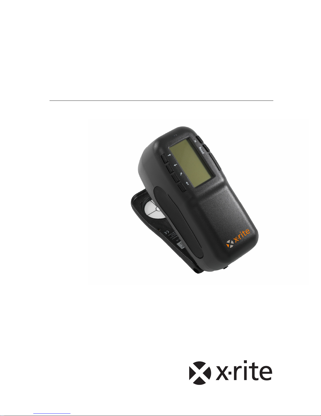
Congratulations on your purchase of an X-Rite 962 or 964
Spectrophotometer. These instruments represent the very latest in
microcontrollers, integrated circuits, optics, and display
technology. As a result, your X-Rite instrument is a rugged and
reliable instrument whose performance and design exhibit the
qualities of a finely engineered instrument, which is not
surpassed.
To fully appreciate and protect your investment, we suggest that you
take the necessary time to read and fully understand this manual. As
always, X-Rite stands behind your instrument with a one-year limited
warranty, and a dedicated service organization. If the need arises,
please don’t hesitate to call us.
Thank you for your trust and confidence.
X-Rite, Incorporated
Page 3

962/964
SPECTROPHOTOMETER
ii
Federal Communications Commission Notice
This equipment has been tested and found to comply with the limits for a Class A digital device,
pursuant to Part 15 of the FCC Rules. These limits are designed to provide reasonable protection
against harmful interference when the equipment is operated in a commercial environment. This
equipment generates, uses, and can radiate radio frequency energy and, if not installed and used
in accordance with the instruction manual, may cause harmful interference to radio
communications. Operation of this equipment in a residential area is likely to cause harmful
interference in which case the user will be required to correct the interference at his own
expense.
NOTE: Shielded interface cables must be used in order to maintain compliance with the desired
FCC and European emission requirements.
Industry Canada Compliance Statement
This Class A digital apparatus complies with Canadian ICES-003.
Cet appareil numérique de la classe A est conforme à la norme NMB-003 du Canada.
AVERTISSEMENT : Des câbles d'interface blindés doivent être utilisés afin de se conformer
aux règlements européens et FCC (USA)sur l'émission.
ACHTUNG: Um das Produkt innerhalb der FCC (Vereinigten Staaten) und den
europäischen Emissions-Richtlinien zu halten, müssen geschirmte Schnittstellenkabel
verwendet werden.
AVISO: Para satisfacer las deseadas regulaciones de emisión para Europa y el FCC,
se debe utilizar los cables de interfaz protegidos contra las interferencias
electromagnéticas.
AVERTISSEMENT: Des câbles d’interface blindés doivent être utilisés afin de se
conformer aux règlements d’émission européens et de FCC (Etats-Unis).
AVVISO: Per conformare con i desiderati regolamentazioni di emissione per Europa
ed il FCC, utilizzare i cavi d'interfaccia protetti contro l'interferenze
electtromagnetiche.
WARNING: This instrument is not for use in explosive environment.
WARNUNG: Das Gerät darf in einer explosiven Umgebung NICHT verwendet
werden.
ADVERTENCIA - NO use este aparato en los ambientes explosivos.
ATTENTION: Cet instrument NE DOIT PAS être utilisé dans un environnement
explosif.
AVVERTIMENTO - NON usare questo apparecchio in ambienti esplosivi.
Page 4

962/964
SPECTROPHOTOMETER
iii
CAUTION: Operational hazard exists if battery chargers other than X-Rite SE3081 (115V) or SE30-77 (100-240V) is used. Use only X-Rite battery pack SP62-7933, other types may burst causing personal injury.
VORSICHT: Betriebs- und Verletzungsgefahr besteht bei Gebrauch von anderen
Adaptern als X-Rite SE30-81 (115 V) oder SE30-77 (100-240 V). Verwenden Sie
nur den X-Rite Akkupack SP62-79-33.
ADVERTENCIA: No use otro cargador de las pilas que no sea la pieza X-Rite
SE30-81 (115V) o SE30-77 (100-240V), para evitar el riesgo de mal
funcionamiento del equipo. Use solamente las pilas SP62-79-33 de X-Rite, es
posible que los otros tipos puedan estallar y causar daños corporales.
ATTENTION: Pour ne pas causer un mauvais fonctionnement de l'appareil,
veillez à utiliser uniquement les chargeurs de batterie X-Rite SE30-81 (115 V) ou
SE30-77 (100-240 V). Veillez aussi à utiliser uniquement la batterie X-Rite SP6279-33, d'autres batteries pouvant exploser et causer des blessures.
AVVERTENZA: Non usare un altro caricabatterie che non è del pezzo X-Rite
SE30-81 (115V) o SE30-77 (100-240V), per evitare il rischio di malfunzionamento
dell'apparecchio. Usare solamente gli accumulatori SP62-79-33 di X-Rite, è possibile
che altri tipi possano scoppiare e causare danno personale.
The Manufacturer: X-Rite, Incorporated
Der Hersteller: 4300 44th Street, S.E.
El fabricante: Grand Rapids, Michigan 49512
Le fabricant:
Il fabbricante:
Declares that: Spectrophotometer
gibt bekannt daß: 962, 964
advierte que:
avertit que:
avverte che:
is not intended to be connected to a public telecommunications network.
nicht an ein öffentliches Telekommunikations-Netzwerk angeschlossen werden soll.
no debe ser conectado a redes de telecomunicaciones públicas.
ne doit pas être relié à un réseau de télécommunications publique.
non deve essere connettuto a reti di telecomunicazioni pubblici.
Page 5

962/964
SPECTROPHOTOMETER
iv
CE DECLARATION
Manufacturer's Name: X-Rite, Incorporated
Manufacturer's Address: 4300 44
th
Street, S.E.
Grand Rapids, Michigan U.S.A.
Model Name: Spectrophotometer
Model No.: 962, 964
Directive(s) Conformance: EMC 89/336/EEC LVD 73/23/EEC
Warning:
This is a class A product. In a domestic environment this product may cause radio
interference in which case the user may be required to take adequate measures.
WEEE
As of August 13, 2005, X-Rite products meet the European Union –
Waste Electrical and Electronic Equipment (WEEE) directive.
Please refer to www.xrite.com
for more information on X-Rite’s
compliance with the WEEE directive.
Page 6

962/964
SPECTROPHOTOMETER
v
Table of Contents
1. Overview and Setup......................................................... 1-1
Instrument Description....................................................................................1-1
Features...........................................................................................................1-1
Features...........................................................................................................1-2
Unpack and Inspect.........................................................................................1-2
Packaging Drawing and Parts List.............................................................. 1-2
Install the Battery Pack...................................................................................1-3
Apply Power...................................................................................................1-3
Charging the Battery Pack..............................................................................1-4
Unlatching the Instrument Shoe......................................................................1-5
Instrument I/O Serial Interface.......................................................................1-6
Attaching the Wrist Strap................................................................................1-6
2. User Interface................................................................... 2-1
What to Expect................................................................................................2-1
Navigation – Basic Key Operation.................................................................2-1
Tab Down key.............................................................................................2-2
Tab Up key .................................................................................................2-2
Enter key.....................................................................................................2-2
Escape key..................................................................................................2-2
Main Menu key...........................................................................................2-2
Read key .....................................................................................................2-2
Colorimetric Screens.......................................................................................2-3
Data Storage Information............................................................................2-3
Color Data Parameters................................................................................2-3
Color Data...................................................................................................2-3
Using the Instrument.......................................................................................2-4
Opening a Menu or Mode...........................................................................2-4
Opening a Pop-Up List Box........................................................................2-4
Opening the Alphanumeric Editor..............................................................2-4
Selecting Single or Multiple Items..............................................................2-5
Selecting Color Data Parameters................................................................2-6
Instrument Indicator Light..........................................................................2-6
Important Measurement Techniques...........................................................2-6
3. Instrument Calibration..................................................... 3-1
General Information........................................................................................3-1
Positioning the Instrument on the Reference..................................................3-2
Page 7

962/964
SPECTROPHOTOMETER
vi
Calibration Procedure .....................................................................................3-3
4. Setting Instrument Configuration................................... 4-1
General Information........................................................................................4-1
Language.........................................................................................................4-1
Measure Options.............................................................................................4-2
Store Samples .............................................................................................4-3
Pass/Fail......................................................................................................4-3
Auto Std......................................................................................................4-3
Averaging ...................................................................................................4-3
Diff Disp.....................................................................................................4-4
Color Options..................................................................................................4-4
Active Functions.........................................................................................4-5
Active Illum/Obs.........................................................................................4-6
Opacity........................................................................................................4-6
Strength.......................................................................................................4-7
Metamerism Index......................................................................................4-8
ΔEcmc Factors............................................................................................4-9
ΔE94 Factors...............................................................................................4-9
Shade Sort.................................................................................................4-10
Database Tools..............................................................................................4-10
Factory Presets..........................................................................................4-11
Clear all Databases....................................................................................4-12
Clear All Samples.....................................................................................4-12
Clear All Tags...........................................................................................4-12
Clear All Projects......................................................................................4-13
Clear All Jobs (964 only)..........................................................................4-13
Clear All Standards...................................................................................4-13
Hardware Setup.............................................................................................4-14
Serial Port .................................................................................................4-16
Read Operation.........................................................................................4-18
Cal Timeout..............................................................................................4-18
Power Down .............................................................................................4-19
Beeper.......................................................................................................4-20
Clock Adjust.............................................................................................4-20
Display......................................................................................................4-22
Main Menu Options......................................................................................4-23
Load Factory Defaults...................................................................................4-24
5. Instrument Operation ...................................................... 5-1
Standards.........................................................................................................5-1
Page 8

962/964
SPECTROPHOTOMETER
vii
Selecting Standard Number........................................................................5-1
Entering Standard Data...............................................................................5-2
Entering Standard Name.............................................................................5-4
Setting Tolerance Limits.............................................................................5-5
Setting Shade Sort Options.........................................................................5-7
Locking/Unlocking Standard......................................................................5-9
Deleting the Standard..................................................................................5-9
Projects .........................................................................................................5-11
Selecting Project Number.........................................................................5-11
Assigning Standards to a Project ..............................................................5-12
Entering Project Name..............................................................................5-12
Locking/Unlocking Project.......................................................................5-13
Add New Project.......................................................................................5-14
Deleting the Project ..................................................................................5-14
QA (Quality Assurance) ...............................................................................5-15
Selecting a Project ....................................................................................5-16
Selecting a Standard..................................................................................5-16
Pass/Fail Operation...................................................................................5-17
555 Shade Sort Operation.........................................................................5-17
Display Difference Indication...................................................................5-18
Storage Operation.....................................................................................5-18
Measurement Averaging...........................................................................5-20
Sample Database Tools.............................................................................5-20
Viewing the Reflectance Graph................................................................5-21
Strength.........................................................................................................5-23
Strength Measurement..............................................................................5-24
Opacity..........................................................................................................5-25
Opacity Measurement...............................................................................5-26
Analyze.........................................................................................................5-27
Compare........................................................................................................5-28
Run Job (964 only) .......................................................................................5-29
6. Service and General Maintenance.................................. 6-1
Repair Information..........................................................................................6-1
Reading Lamp Replacement Information...................................................6-1
Cleaning the Instrument..................................................................................6-1
General Cleaning ........................................................................................6-1
Cleaning the Optics.....................................................................................6-2
Cleaning the Calibration Reference............................................................6-2
Replacing the Battery Pack.............................................................................6-3
7. Appendices....................................................................... 7-1
Page 9

962/964
SPECTROPHOTOMETER
viii
Instrument Specifications................................................................................7-1
Error Messages ...............................................................................................7-2
Parts List (962)................................................................................................7-3
Parts List (964)................................................................................................7-3
Packaging (962)..............................................................................................7-4
Packaging (964)..............................................................................................7-5
Changing the Aperture....................................................................................7-6
Page 10

962/964
SPECTROPHOTOMETER
ix
Proprietary Notice
The information contained in this manual is derived from patent and proprietary data
of X-Rite, Incorporated. This manual has been prepared solely for the purpose of
assisting in the use and general maintenance of this instrument.
The contents of this manual are the property of X-Rite, Incorporated and are
copyrighted. Any reproduction in whole or part is strictly prohibited.
Publication of this information does not imply any rights to reproduce or use this
manual for any purpose other than installing, operating, or maintaining this
instrument. No part of this manual may be reproduced, transcribed, transmitted,
stored in a retrieval system, or translated into any language or computer language, in
any form or by any means, electronic, magnetic, mechanical, optical, manual, or
otherwise, without the prior written permission of an officer of X-Rite, Incorporated.
This instrument may be covered by one or more patents. Refer to the instrument for
actual patent numbers.
Copyright © 2007 by X-Rite, Incorporated
“ALL RIGHTS RESERVED”
X-Rite® is a registered trademark of X-Rite, Incorporated. All other logos, brand name s, and
product names mentioned are the properties of their respective holders.
Warranty Information
X-Rite, Incorporated (“X-Rite”) warrants each instrument manufactured to be free of
defects in material and workmanship (excluding battery pack) for a period of 12
months. This warranty shall be fulfilled by the repair or replacement, at the option of
X-Rite, of any part or parts, free of charge including labor, F.O.B. its factory or
authorized service center.
This warranty shall be voided by any repair, alteration, or modification, by persons
other than employees of X-Rite, or those expressly authorized by X-Rite to perform
repairs, and by any abuse, misuse, or neglect of the product, or by use not in
accordance with X-Rite’s published instructions.
X-Rite reserves the right to make changes in design and /or improvements to its
products without any obligation to include these changes in any products previously
manufactured. Correction of defects by repair or replacement shall constitute
fulfillment of all warranty obligations on the part of X-Rite.
THIS WARRANTY IS EXPLICITLY IN LIEU OF ANY OTHER EXPRESSED OR
IMPLIED WARRANTIES, INCLUDING ANY IMPLIED WARRANTY OF
MERCHANTABILITY OR FITNESS FOR ANY PARTICULAR PURPOSE. THIS
WARRANTY OBLIGATION IS LIMITED TO REPAIR OR REPLACEMENT OF
THE UNIT RETURNED TO X-RITE OR AN AUTHORIZED SERVICE CENTER
FOR THAT PURPOSE.
This agreement shall be interpreted in accordance with the laws of the State of
Michigan and jurisdiction and venue shall lie with the courts of Michigan as selected
by X-Rite, Incorporated.
Page 11

962/964
SPECTROPHOTOMETER
x
Page 12
962/964
SPECTROPHOTOMETER
1-1
1. Overview and Setup
Instrument Description 1-1
Features 1-2
Unpacking and Inspection 1-2
Installing the Battery Pack 1-3
Applying Power 1-4
Charging Battery Pack 1-5
Unlatching the Instrument Shoe 1-6
Instrument I/O Serial Interface 1-7
Attaching the Wrist Strap 1-7
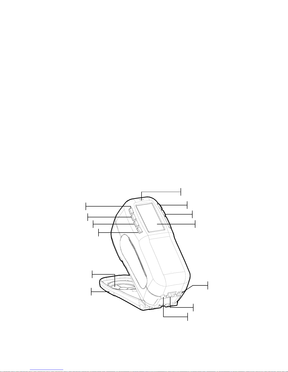
Instrument Description
The X-Rite 962 and 964 Spectrophotometer’s compact spectral
engine utilizes X-Rite’s DRS (Dynamic Rotational Sampling)
technology, allowing accurate and precise measurements. This
instrument has intuitive keys and a high-contrast graphic
display.
Target Window
Graphic Display
I/O Port
Power Input
Escape Key
Tab Key
Tab Key
Main Menu Key
Read Key
Battery Switch
Indicator Light
Enter Key
Instrument Shoe
Page 13

CHAPTER ONE
1-2
Features
Automatic Shut-Off
To increase battery life, the instrument automatically turns
itself off if it is not used within a user-defined time—between
10 and 240 seconds. See Setting Instrument Configuration,
Section Four for more information. The instrument turns back
on whenever a key is pressed, a measurement is taken, or the
adapter is plugged in.
Graphic Display
A high contrast, 128 x 256 pixel graphics display provides a
versatile means of displaying the measured data.
Indicator Light
A multi-color LED at the top of the instrument provides visual
feedback on the status of measurements.
Quick Color Compare
An operator can take a quick measurement and comparison of
two colors. This allows the instrument to be used for taking
quality control readings in a time-efficient manner without the
necessity of creating tolerances.
Unpack and Inspect
After removing the instrument from the shipping carton,
inspect it for damage. If any damage has occurred during
shipping, immediately contact the transportation company. Do
not proceed with installation until the carrier’s agent has
inspected the damage.
Your instrument was packaged in a specially designed carton to
assure against damage. If shipment is necessary, the instrument
should be packaged in the original carton. If the original carton
is not available, contact X-Rite to have a replacement carton
shipped to you.
Packaging Drawing and Parts List
Check your packaging contents against your packing list and
original order. A detailed packaging drawing and parts list are
included in the appendices of this manual.
Page 14
OVERVIEW AND SETUP
1-3
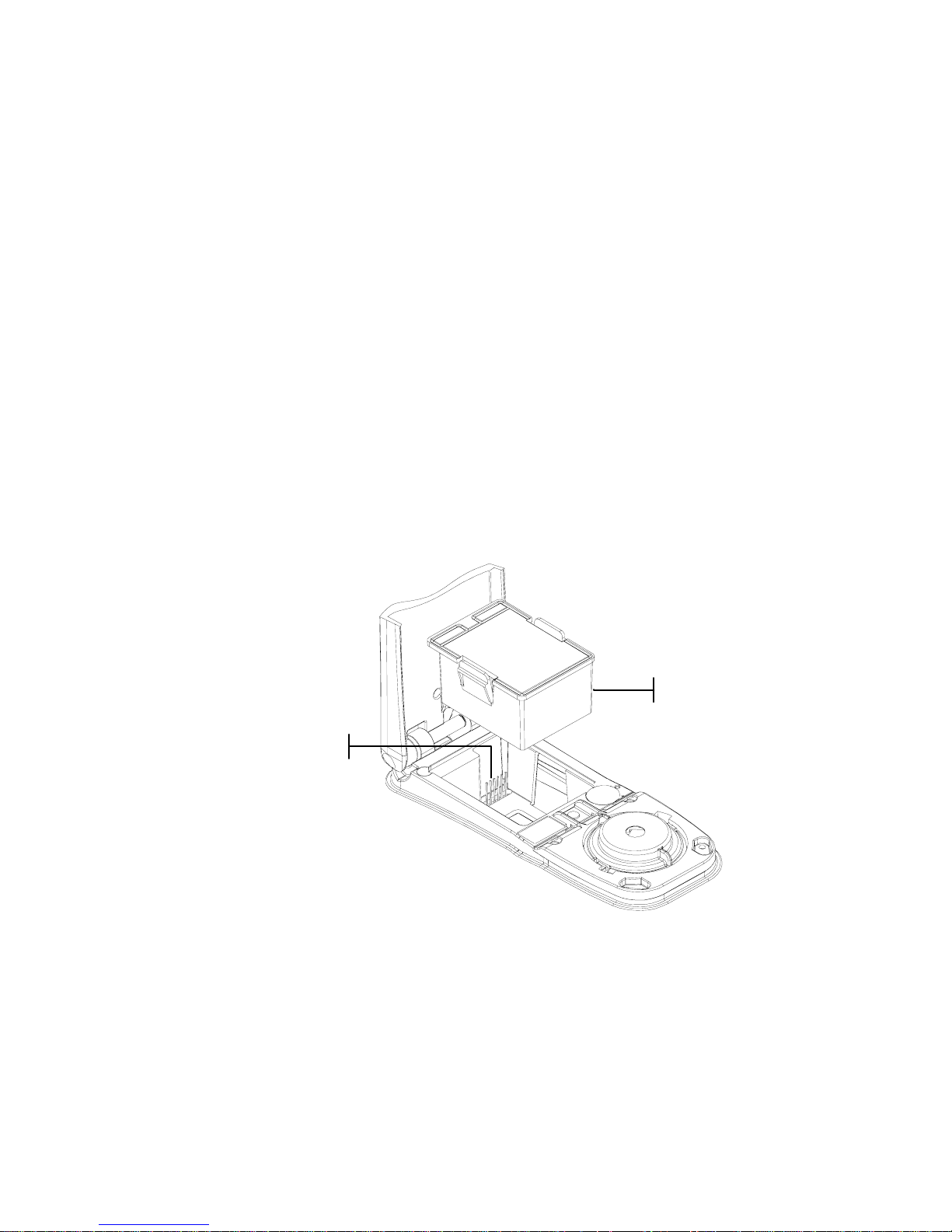
Install the Battery Pack
The instrument is shipped from the factory with the battery
pack removed. The battery pack is located in a carrying case
compartment and must be installed before the instrument is
used.
1. Hold the shoe next to the instrument housing and lift
upward on the spring-loaded latch (refer to Unlatching the
Instrument Shoe). Open the shoe perpendicular to the
instrument housing.
2. Carefully rotate the instrument over and rest it on its top.
3. Slide the battery pack into the compartment with the
battery connector facing down and to the back of the
instrument.
4. Press down on the pack until the connector is prop erly
seated and the tabs click into position.
Apply Power
The Battery switch—located on the back of the instrument—
turns the instrument off and on during battery operation. When
the AC adapter is attached, the instrument remains on and the
battery switch has no effect.
Battery Connecto
r
Battery Pack
Page 15

CHAPTER ONE
1-4
As an added feature to conserve battery life, the instrument
automatically powers down when it is not in use. You can
define the amount of time it takes to initiate a power-down
within the instrument configuration options (see Section Four).
Taking a measurement or pressing a key turns the instrument
back on during a power-down. However, if the instrument is
turned off with the battery switch you must turn it back on with
the battery switch.
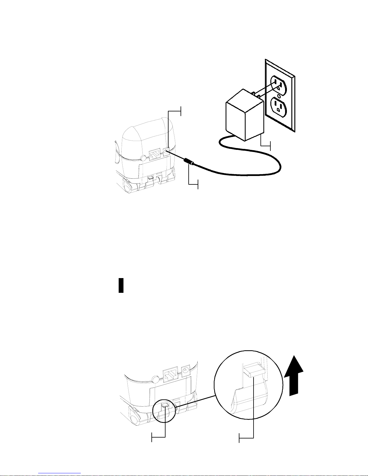
Charging the Battery Pack
NOTE: The battery pack must be installed before plugging in the AC
Adapter.
Only use the AC Adapter supplied or the optional battery
charger (available through X-Rite) to charge the battery pack.
The battery pack must remain in the instrument at all times to
operate.
Before initial “remote” use of the instrument, charge the battery
pack for approximately four hours. However, if immediate use
is required, the instrument can be operated “tethered” to the AC
adapter during battery charging.
To attach the AC adapter:
1. Verify that the voltage indicated on the adapter complies
with the AC line voltage in your area. If not, contact
X-Rite or an authorized representative.
2. Insert the small plug from the adapter into the power-input
connector on the instrument. (If you are using serial cable
SE108-92, you may insert the small plug into the power
connector at the end of the cable.)
3. Plug the adapter into an AC wall receptacle.
Battery Switch
A
C Adapter Input
Page 16
OVERVIEW AND SETUP
1-5
Unlatching the Instrument Shoe
The shoe can be pivoted open 180° from its closed position.
This feature is useful when taking measurements on a surface
that does not allow room for the shoe, or a measurement fixture
that does not require the shoe. Measurements are then activated
using the Read key (see Instrument Configuration for more
details on the Read key).
NOTE: The instrument must be calibrated with the target window
removed when using the instrument with the shoe extended.
To Unlatch the Instrument Shoe:
1. Hold the shoe next to the instrument housing and lift
upward on the spring-loaded latch.
2. Slowly allow the shoe to pivot toward the back of the
instrument and release the latch.
Shoe Latch
Lift Upwards
Small Plug
Adapter
Power Input
Page 17
CHAPTER ONE
1-6
To latch the Instrument Shoe:
1. Simply close the shoe to the instrument. The latch is
spring-loaded and automatically latches to the shoe catch.
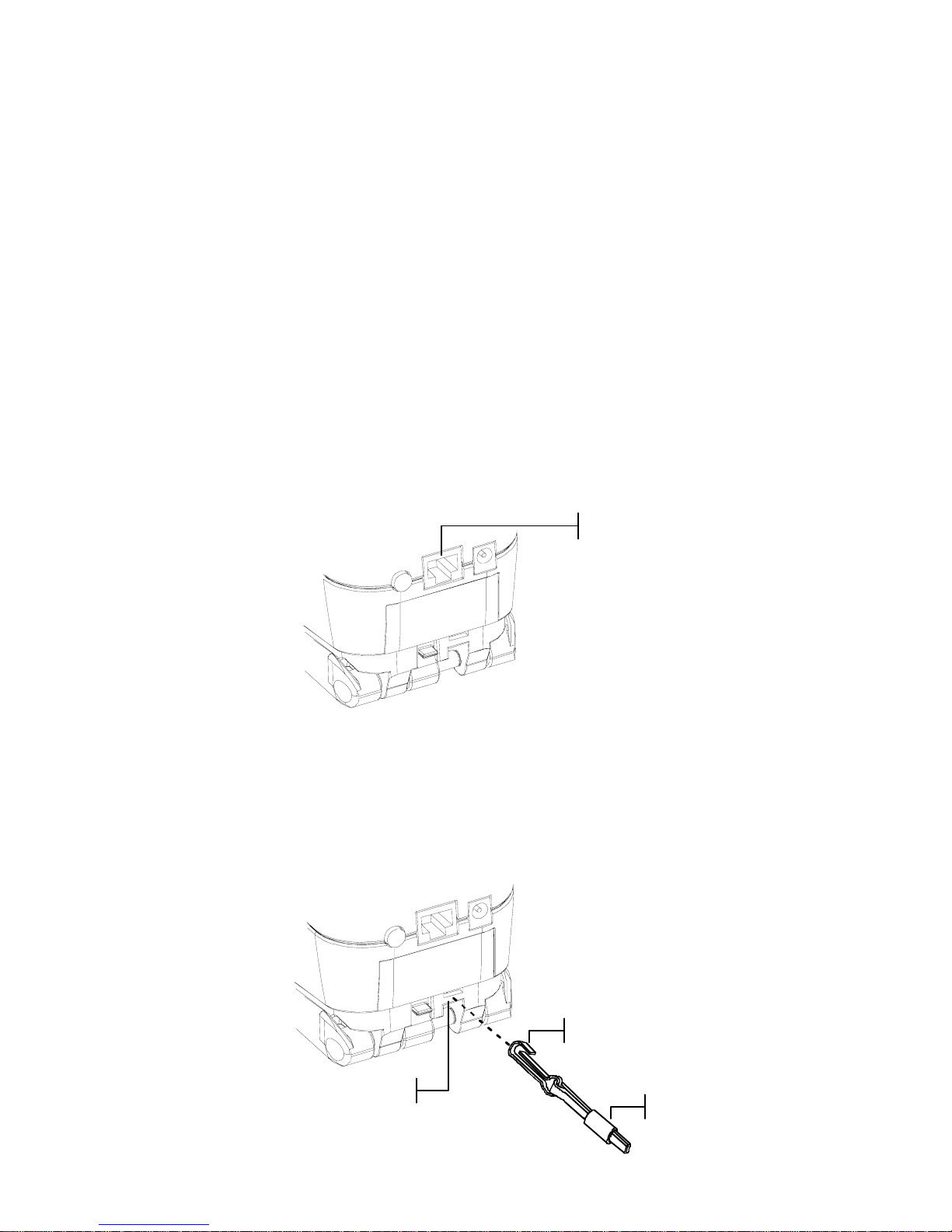
Instrument I/O Serial Interface
Your instrument can be connected to a computer or printer
using a serial RS-232 interface cable and adapter. X-Rite
carries a variety of adapters to meet your requirements.
To install the interface cabling:
1. Insert the modular end of the interface cable into the I/O
port located on the back of the instrument. The cable
connector “clicks” when properly attached.
2. If required, attach an additional adapter to the other end of
the cable.
Attaching the Wrist Strap
A security wrist strap is included to safeguard against
accidentally dropping of the instrument. The strap is attached to
the instrument by simply securing the clasp to the designated
location on the back of the housing. Adjust the strap by sliding
the sleeve to tighten around your wrist.
Connection Location
Strap Clasp
A
djustable Sleeve
Serial I/O Port
Page 18
962/964
SPECTROPHOTOMETER
2-1
2. User Interface
What to Expect 2-1
Navigation – Basic Key Operation 2-1
Measurement Mode Screens 2-3
Using the Instrument 2-4
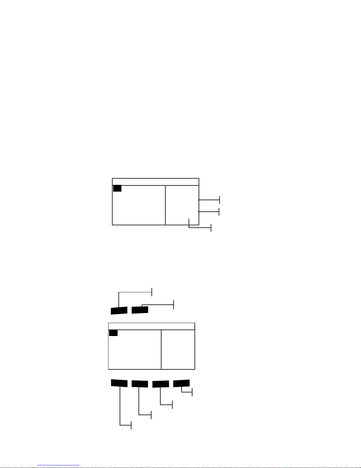
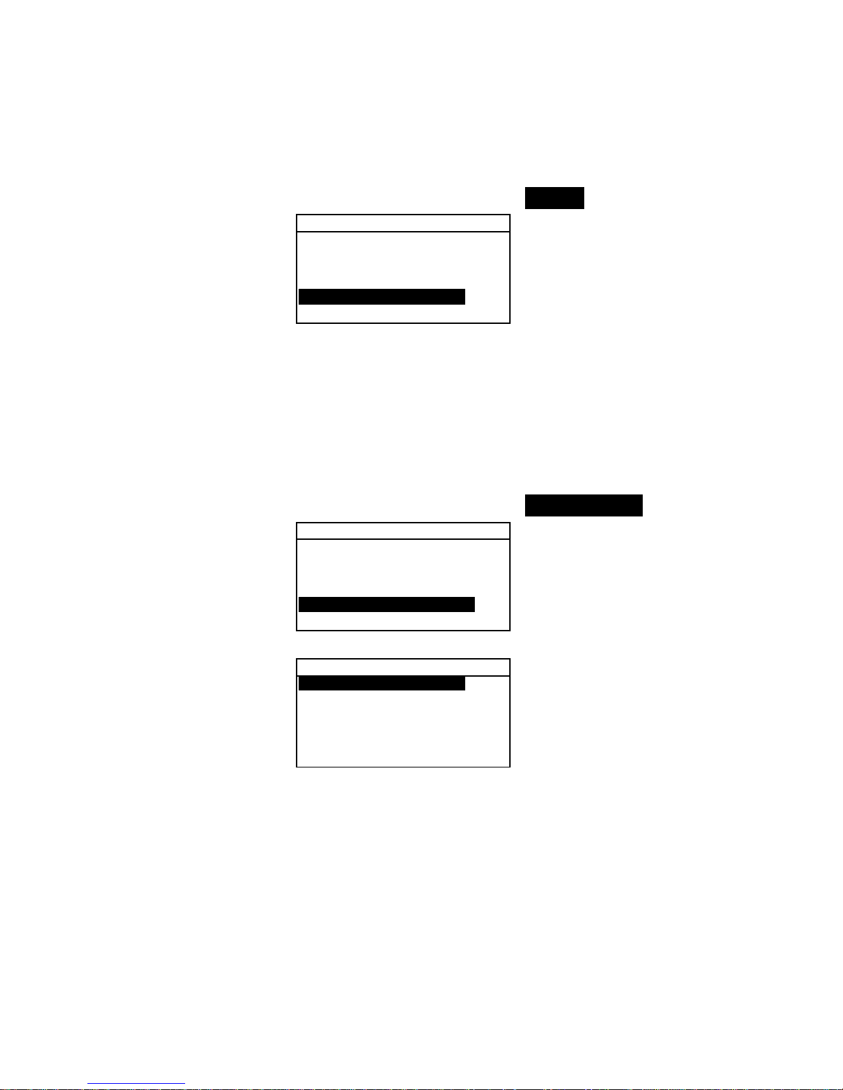
What to Expect
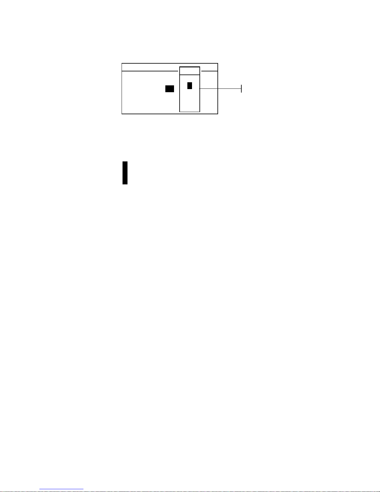
When the instrument is powered-up, the main (top level) screen
appears. The main screen consists of two areas, Main Menu and
Instrument Data. The left side of the screen lists all available
modes. The right side of the screen lists instrument model and
firmware version information.
Navigation – Basic Key Operation
Perform reading and menu/option navigation with the six keys
arranged around the display screen. Each key has a unique
symbol for performing a specific operation.
–
MAIN MENU–
QA
Analyze
Compare
Strength
Opacity
^
X—Rite
964
——————
XXXX
******
!$@
#
%
Read
Main Menu Key
Instrument Read Key
Tab Up Key
Tab Down Key
Escape Key
Enter Key
–
MAIN MENU–
QA
Analyze
Compare
Strength
Opacity
^
X—Rite
964
——————
XXXX
******
Serial Numbe
r
Firmware Version
Instrument Model
Page 19

CHAPTER TWO
2-2
Tab Down key
Advances the highlighted bar (reverse image) to the next
available “tab stop.” A “tab stop” indicates an item that can be
acted on further, such as a measurement or a setting opt i o n. Tab
stops generally follow a left-to-right or top-to-bottom sequence.
When the last tab stop is reached in the main menu, the next
key press returns to the first stop. The key is also used to select
alpha/numeric characters in the edit mode.
Tab Up key
Performs the same function as the Tab Down key except in
reverse order. Tab stops follow a right-to-left or bottom-to-top
sequence.
Enter key
Activates the highlighted item. If the item can be set on or off,
pressing the key toggles the option between on and off. When
entering an active mode from the main menu, the active mode
is displayed with the highlight on the first required operation in
the mode.
Escape key
Backs up the instrument screen one menu level. For example, if
an option or value is being modified at the time the key is
pressed, the edits are aborted and the previous screen or menu
appears. The only exception to this is when the Enter key is
used to toggle an option. In this case, the Escape key exits the
menu without aborting the setting.
Main Menu key
Returns the instrument screen to the main menu. This is a quick
exit out of any mode. If any option or value is being modified
at the time the key is pressed, the edits are aborted and the
previous setting reinstated.
Read key
If activated in configuration, initiates a reading when pressed.
Refer to Setting Instrument Configuration, Section Four for
additional information.
Page 20
USER INTERFACE
2-3
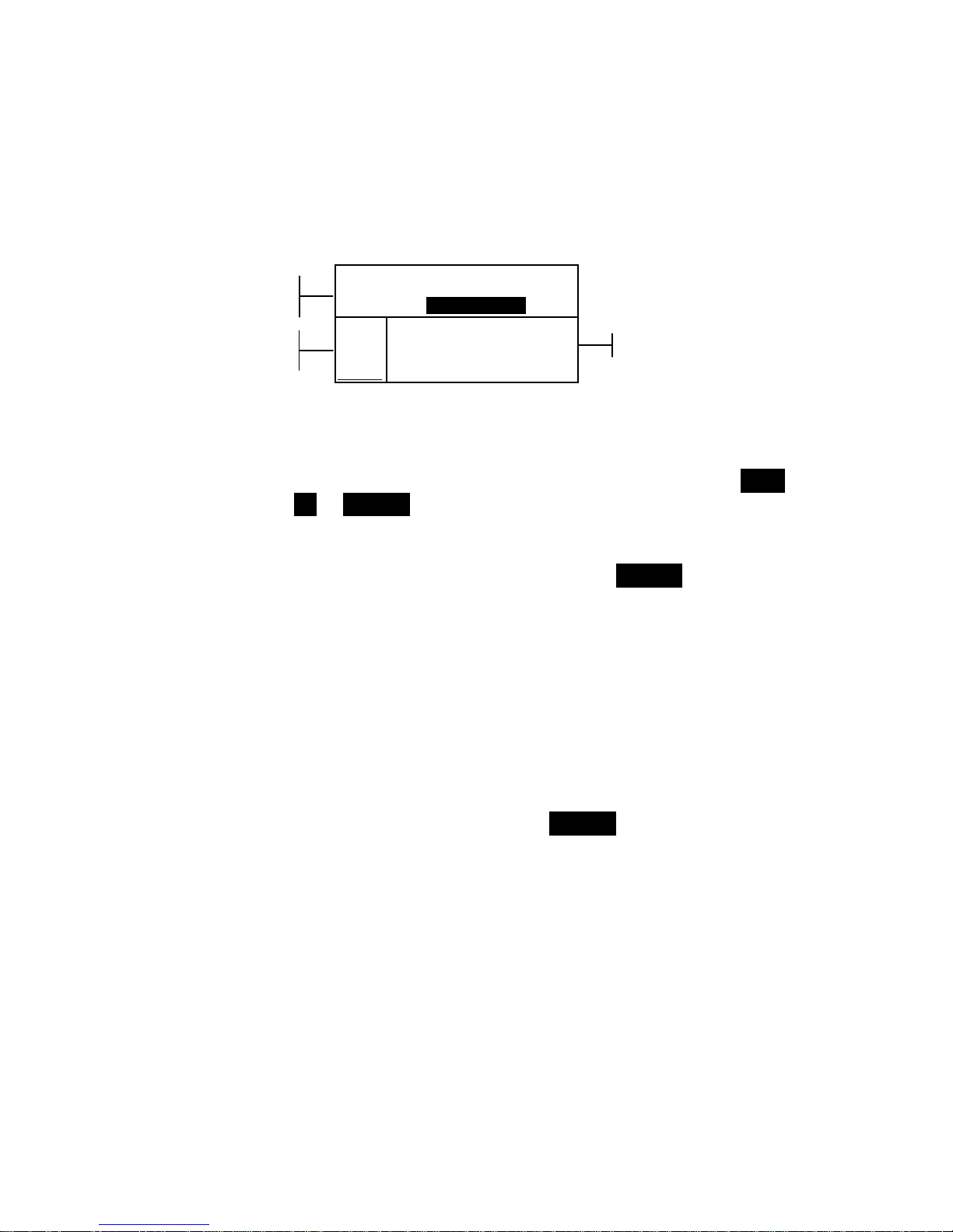
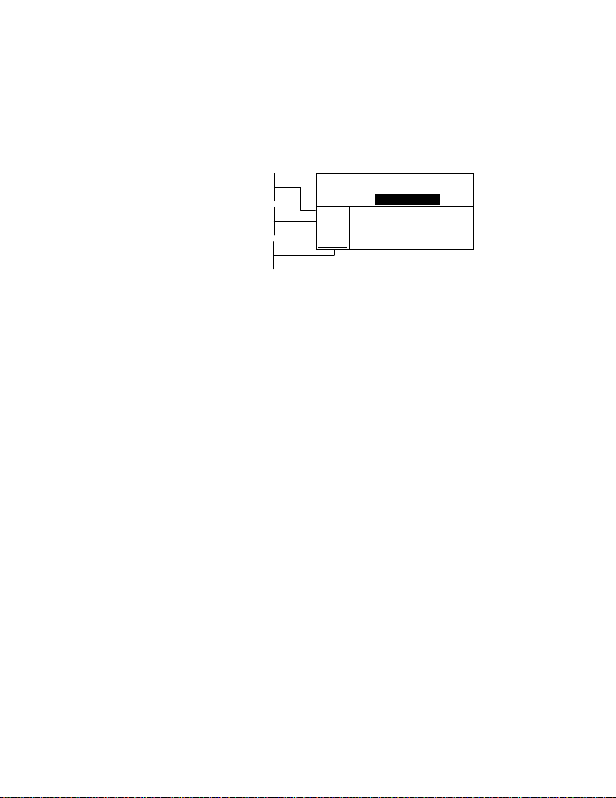
Colorimetric Screens
The QA, Analyze, Compare, Strength, and Opacity screens
consist of three main areas: Data Storage Information, Color
Data Parameters, and Color Data.
Proj 1: Cartons
Std 1: Red Sample
Sample: #10 11:23
L*a*b*
D65/10
....
.
.
.
...
ΔL* +0.05
L* 88.25 Δa* —0.03
a* —4.71 Δb* —0.14
b*+36.64 ΔE* 0.16
Data Storage Information
When in QA, Strength, or Opacity mode, this area displays the
project, standard, and sample information associated with
stored data. Repeatedly pressing the Enter key # whe n Proj
## or Std ## is highlighted pages through the available
projects or standards stored in the instrument (or hold down the
Enter key # to access a specific number from the editor
dialog). Pressing the Enter key # when Sample is highlighted
activates the sample Database Tools menu. Pressing the Enter
key # when a project name or a standard name is highlighted
displays the setup information for the selected item. When the
instrument is in storage mode, repeatedly pressing the Enter
key # with the sample number highlighted pages through
samples associated with the current standard and project (or
hold down the Enter key # to access a specific number from
the editor dialog).
When in Analyze mode, this area displays the standard’s name.
Pressing the Enter # key when Std ## is highlighted pages
through the available standards stored in the instrument.
When in Compare mode this area displays measurement
instructions.
Color Data Parameters
This portion of the screen lists the current parameters for the
values displayed in the Color Data Area. See Selecting Color
Data Parameters for additional information.
Color Data
This portion of the screen instantaneously displays
measurement data for the active measurement mode.
Depending on the mode and configurat i o n settings, data
appears as absolute or absolute and difference values.
Data Storage
Information
1.1.1.1.1.1.1Color
Color Data
Parameters
Page 21
CHAPTER TWO
2-4
Using the Instrument
There are several techniques used to navigate through the
instrument screens, select functions and settings, and determine
values and names.
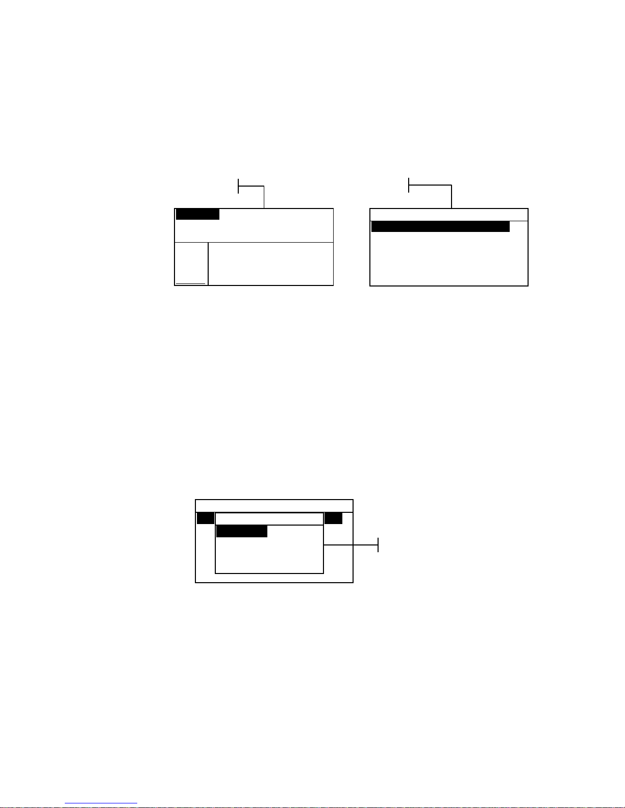
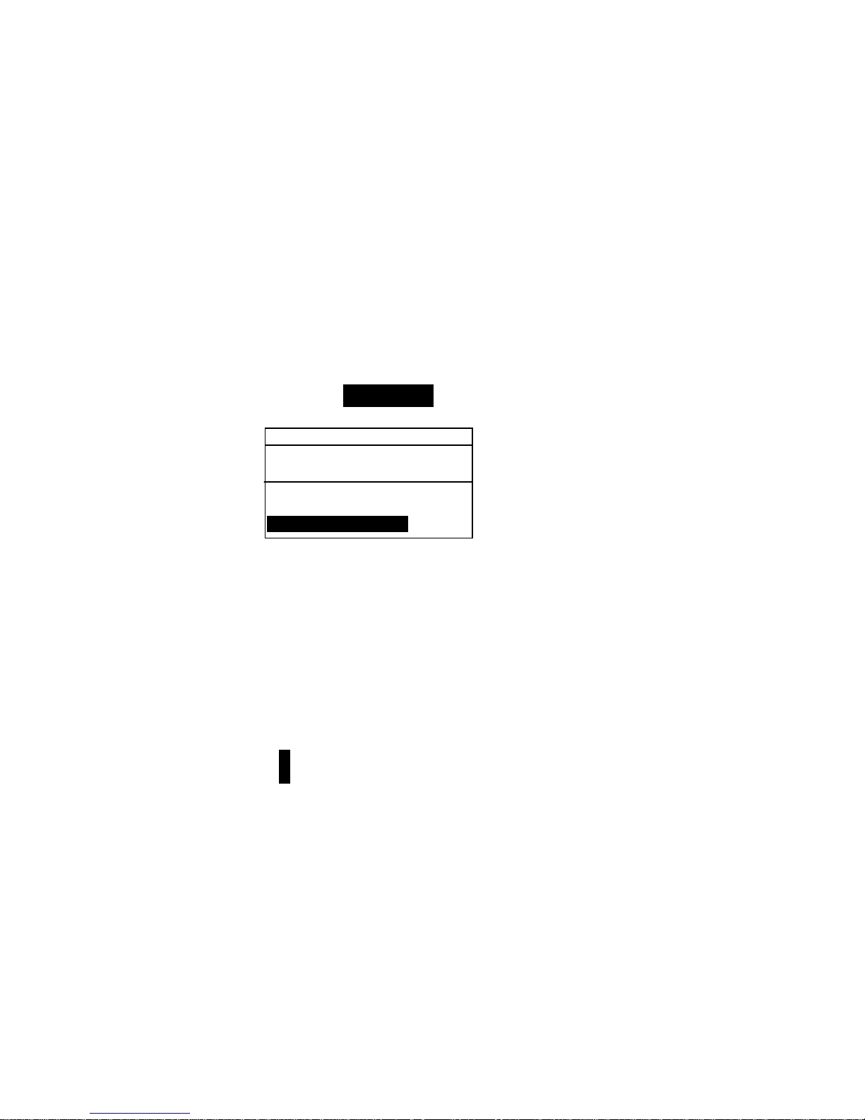
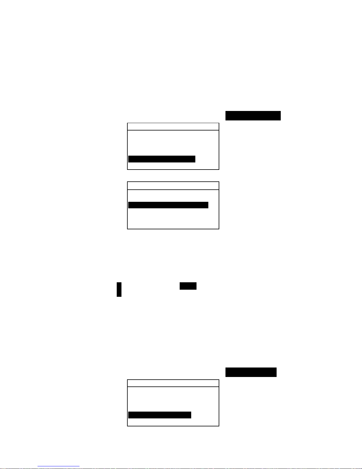
Opening a Menu or Mode
Opening a mode or a menu gives you access to additional items
related to the menu or specific information for a mode. Below
are examples of typical mode and menu screens.
To open a mode or menu:
1. Use the Tab Up key $ or Tab Down key @ to highlight the
desired mode or menu item.
2. Press the Enter # key.
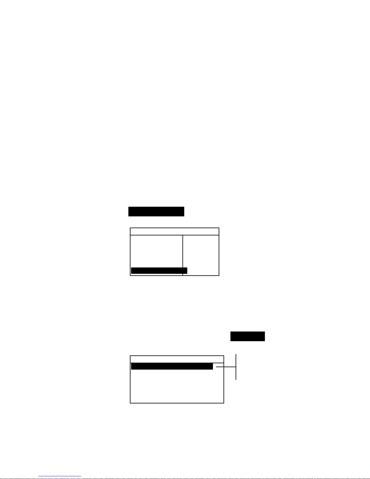
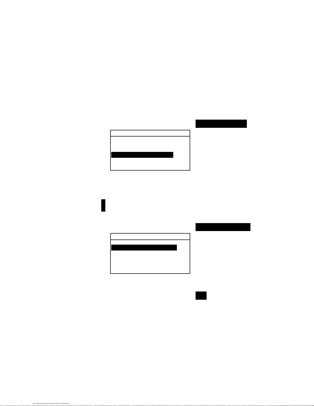
Opening a Pop-Up List Box
Opening a pop-up list box allows you to select items and/or
change settings for a selection or function. Below is an example
of a list box.
To open a pop-up list box:
1. Use the Tab keys $@ to highlight the desired selection or
function.
2. Press the Enter # key to access the pop-up list box.
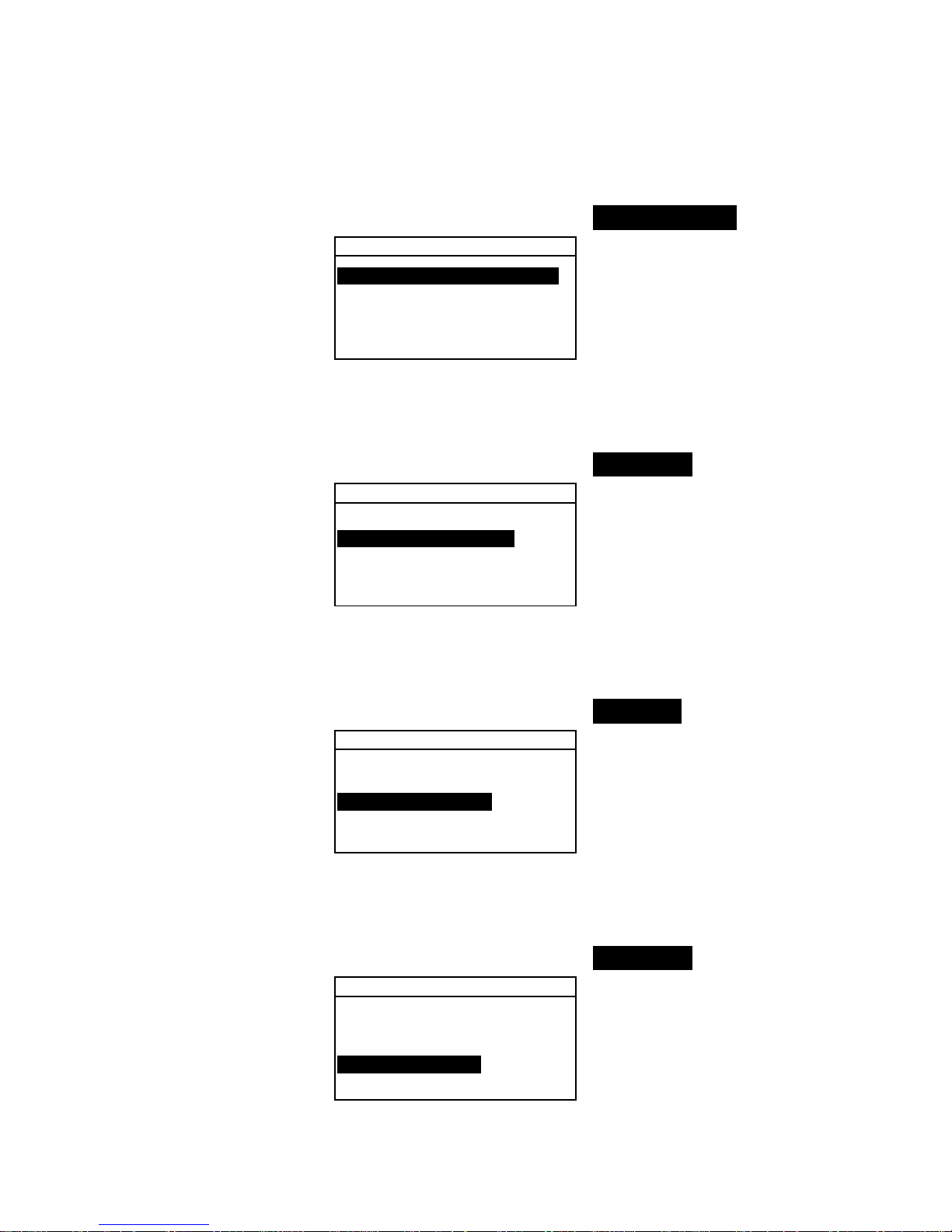
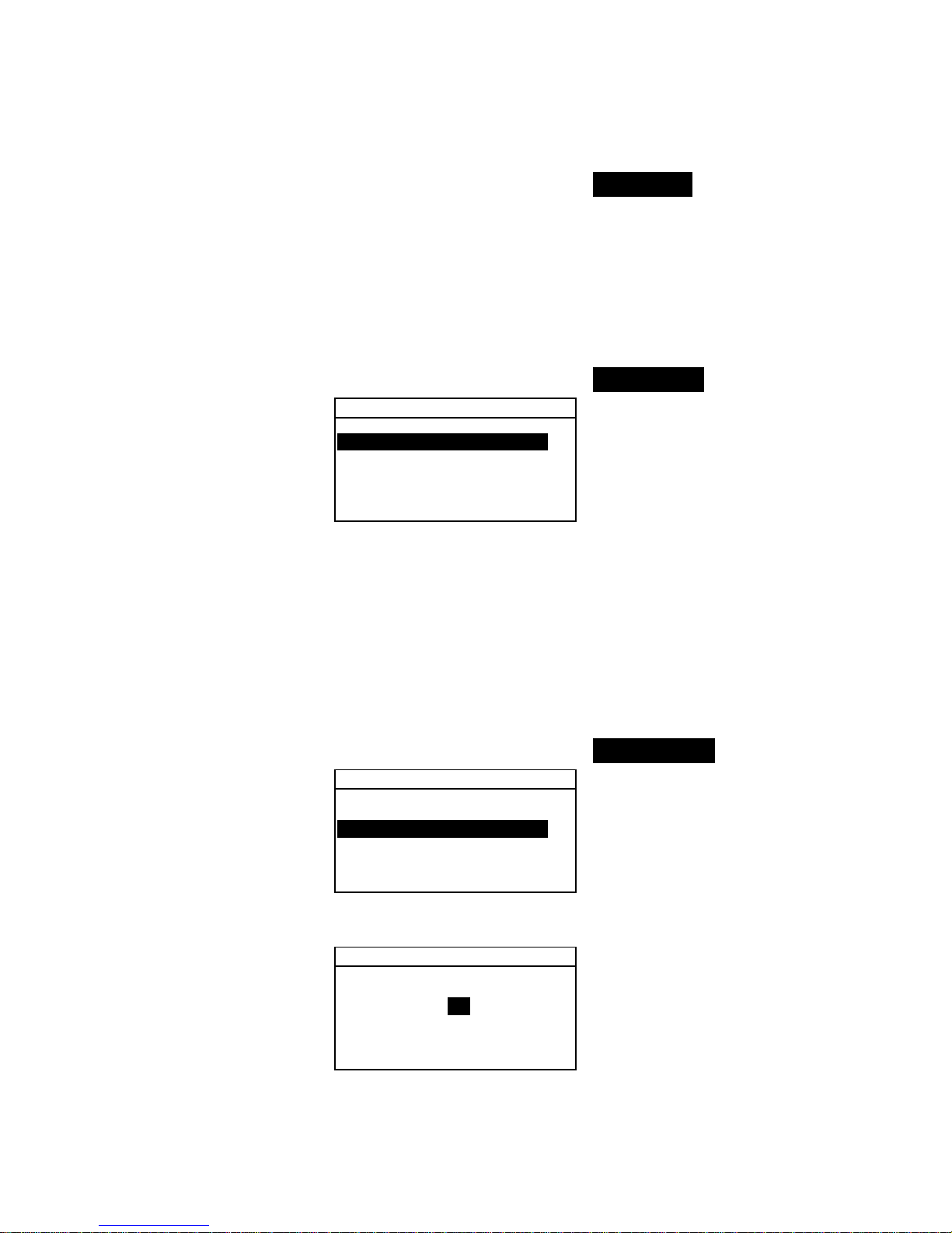
Opening the Alphanumeric Editor
Several functions that utilize names and values are edited using
the alphanumeric editor. Selecting Clear in the editor provides
a quick method of removing all values or characters in the
string. Pressing the Tab keys $@ simultaneously clears the
selected character. Below is an example of the editor.
Configuration
Language :English
Measure Options...
Color Options...
Database Tools...
Hardware Setup...
Set Language
English
Deutsch
Français
↓
Pop-Up List Box
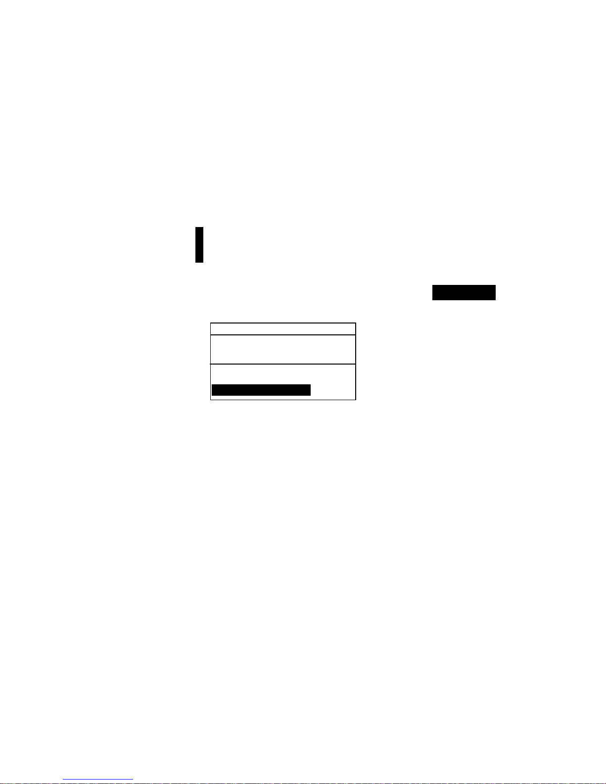
CONFIGURATION
Language :English
Measure Options...
Color Options...
Database Tools...
Hardware Setup...
Main Menu Options...
Configuration Menu
Proj 1: Cartons
Std 1: Red Sample
Sample: #10 11:23
L*a*b*
D65/10
....
.
.
.
...
ΔL* +0.05
L* 88.25 Δa* —0.03
a* —4.71 Δb* —0.14
b*+36.64 ΔE* 0.16
QA Function
Page 22
USER INTERFACE
2-5
To open the editor:
3. Use the Tab keys $@ to choose the desired digit or number
(arrows above and below designate selection).
4. Press the Enter # key to access the editor.
NOTE: If the editor menu includes letters and symbols (such as the
standard name editor), you can press the Enter key # again to quickly
page through groups of letters, symbols, and numbers.
5. Use the Tab keys $@ to highlight the desired item.
6. Press the Enter # key to select the highlighted character
and exit the editor.
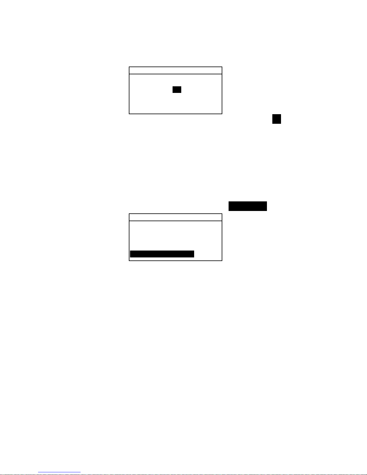
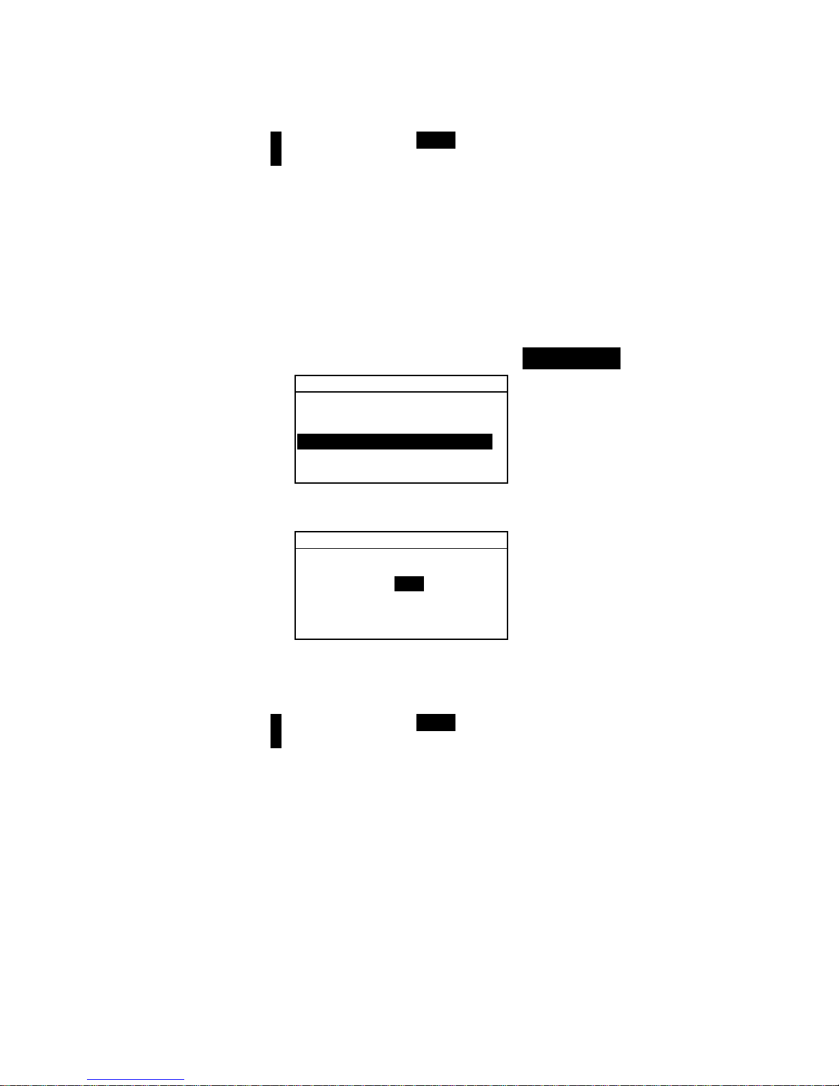
Selecting Single or Multiple Items
Many settings and modes allow you to select single or multiple
items from a list or menu. Lists can be found in every type of
screen: menus, editors, or mode screens.
To select a single item from a list:
1. Use the Tab keys $@ to highlight the desired item in the list.
2. Press the Enter key # to save your selection (and return to
the previous screen).
To select multiple items from a list:
1. Use the Tab keys $@ to highlight the first item in the list.
2. Press the Enter key # to toggle an arrow (>) on or off for
the item (an arrow indicates on).
3. Use the Tab keys $@ to move the highlight to the next item
in the list and press the Enter key # to set status.
4. Press the Escape key ! to return to the previous screen.
Set Cal Interval
CLEAR
↓
24
↑
On
Save & Exit
0 -9
↑
2
3
4
↓
Editor
Page 23
CHAPTER TWO
2-6
Selecting Color Data Parameters
Colorimetric data can be viewed under varying illuminant
observer conditions, and color space/indices. The color data
immediately changes to reflect the selected parameter.
To select a color data parameter:
1. Use the Tab keys $ @ to highlight the desired param e t er.
2. Press the Enter key # to page though the parameters.
Instrument Indicator Light
The LED located next to the display illuminates various color
conditions during instrument measurements.
• Flashing Amber – instrument calibration is required or
measurement aborted.
• Solid Amber – measurement is taking place.
• Solid Green – measurement passed tolerancing
requirement in QA mode.
• Solid Red – measurement failed tolerancing requirements
in QA mode.
Important Measurement Techniques
In order for the instrument to obtain accurate and repeatable
measurements, the bottom of the shoe must be flat on the
surface to be measured. When measuring curved items where a
flat surface is not available, a fixture should be used. A fixture
allows accurate positioning of the sample tangent to the
measurement plane. If the item to be measured is smaller than
the shoe, you may want to make a platform—at the same height
as the item—for the rest of the instrument to sit on. The
instrument can also be used with the shoe fully extended 180°
from the closed position. A measurement is then activated
using the Read key.
A/2, A/10, C/2,
C/10, D50/2, etc.
L*C*h°, XYZ, Lab
(Hunter), etc.
Selecting the curve activates
the reflectance graph
Proj 1: Cartons
Std 1: Red Sample
Sample: #10 11:23
L*a*b*
D65/10
....
.
.
.
...
ΔL* +0.05
L* 88.25 Δa* —0.03
a* —4.71 Δb* —0.14
b*+36.64 ΔE* 0.16
Page 24
962/964
SPECTROPHOTOMETER
3-1
3. Instrument Calibration
General Information 3-1
Positioning the Instrument
on the Reference 3-2
Calibration Procedure 3-3
General Information
Under normal circumstances, the instrument should be
calibrated at least once a day.
At the Main Menu, use the Tab Up $ or Tab Down @ key to
highlight Calibrate. Press the Enter key # to access the
Calibration Menu.
CALIBRATION
< Measure White Ref>
Status: Cal time up
S/N: ******
Ap Size: 8.0mm
The bottom portion of the calibration screen displays
information regarding the calibration status, cal plaque serial
number, and instrument aperture size. The status line displays
as either
Cal OK or Cal Required. Cal time up indicates that
calibration is required. Cal Ok indicates that no calibration is
required at this time. The serial number displayed on the
second line should match the serial number listed on your
calibration reference. The aperture size line displays the current
size. The line is also used to select the aperture size.
NOTE: Refer to Appendices for a detailed procedure on changing the
aperture setting and size.
Page 25
CHAPTER THREE
3-2
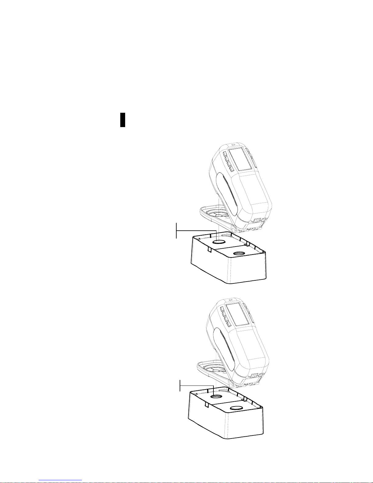
Positioning the Instrument on the Reference
The calibration reference consists of a ceramic disk for white
calibration measurements and a trap opening for black
calibration measurements. The instrument shoe fits snuggly in
both positions. Refer below for proper positioning.
NOTE: Make sure the calibration reference is clean before use.
Refer to the calibration cleaning procedure in Section Six.
White Reading Position
Black Reading Position
White Ceramic
Disk
Port Opening
Page 26
INSTRUMENT CALIBRATION
3-3
Calibration Procedure
A normal calibration procedure consists of one white
measurement followed by one black measurement (two white
and two black measurements are required if an aperture change
is made). The instrument features a built in calibration timer
that can be set from 1-96 hours. Refer to Instrument
Configuration for proced ure. The instrument then notifies you
when a calibration is required.
NOTE: The instrument must be calibrated with the target window
removed when using the instrument with the shoe extended
(unlatched).
To perform a calibration:
1. Press Tab Up $ or Tab Down @ to highlight Calibrate.
Press Enter key # to access the calibration mode.
2. Position the target window over the white ceramic disk as
previously explained.
3. Press the instrument firmly to the shoe. Hold steady until
the screen indicates the white calibration is completed.
Release instrument when <
Success!> is displayed.
4. If an aperture change was made, repeat step three and
measure the white reference again.
5. Position the target window over the black port opening as
previously explained.
6. Press the instrument firmly to the shoe. Hold steady until
the screen indicates the black calibration is completed.
7. If an aperture chang e was made, repeat step six and
measure the black port opening again.
8. Store the calibration reference in a dry, dust free area,
away from direct exposure to light.
CALIBRATION
< Measure White Ref>
Status: Cal Required
S/N: ******
Ap Size: 8.0mm
Page 27

CHAPTER THREE
3-4
Page 28
962/964
SPECTROPHOTOMETER
4-1
4. Setting Instrument Configuration
General Information 4-1
Language 4-1
Measure Options 4-2
Color Options 4-5
Database Tools 4-11
Hardware Setup 4-15
Main Menu Options 4-24
Load Factory Defaults 4-24
General Information
The Configuration menu consists of a series of settings that allow
you to customize your instrument for your particular application.
To open the Configuration menu:
1. Repeatedly press the Tab Down @ key to highlight
Configuration. Press the Enter key # to access the
Configuration Menu.
–MAIN MENU–
↑
Calibrate
Standards
Projects
Run Job
X—Rite
964
——————
XXXX
******
Language
The Language configuration allows you to select the language
you want to display on your instrument. The instrument resets
whenever the language is changed.
To select a language:
1. Use the Tab keys $@ to highlight Language.
2. Press the Enter # key to access the
Language editor.
Configuration
Language :English
Measure Options...
Color Options...
Database Tools...
Hardware Setup...
Main Menu Options...
3. Use the Tab keys $@ to highlight the desired language.
4. Press the Enter key # to save the selected language. The
instrument restarts with the selected language active.
Configuration
English, Deutsch,
Español, Francais,
Italiano, Português
Page 29

CHAPTER FOUR
4-2
Measure Options
The Measure Options configuration allows you to determine
the following settings:
• Store Samples – Allows you to enable (on) or disable (off)
the measurement storage capabilities of the instrument.
When set to “On”, measured samples are stored in the
instrument database until manually deleted.
• Pass/Fail – Allows you to enable (on) or disable (off) the
pass and fail capabilities of the instrument. When set to
“On”, the measured data is compared to the current standard
value (auto selected as closest color if Auto Std is On) and
the associated tolerance to determine pass/fail status.
• Auto Std – Sets the automatic standard option. When Auto
Standard is enabled (on), the standard with the smallest DE
is automatically selected during a difference measurement.
When Auto Standard is disabled (off), a standard must be
manually selected before a difference measurement.
• Averaging – Sets the averaging option. Selects the number
of readings averaged into a single measurement (0-99).
• Diff Disp – Selecting “Numbers” causes delta values to
display during difference measurements. This option is
automatically enabled when standards are entered or
downloaded from a software program. When set to
“Words”, color difference is displayed as words (e.g.,
brighter, duller, etc.). This setting is only available for
L*a*b* and L*C*h° color difference data. When disabled
(off), no delta values are displayed during measurements.
NOTE: No words display for an attribute that is less than 1/7th of
the DE value. A value less than this amount is considered
insignificant compared to the total difference. Delta values
greater than 10.00 display numerically.
To open the Measure Options menu:
1. Use the Tab keys $@ to highlight Measure Options.
Configuration
Language :English
Measure Options...
Color Options...
Database Tools...
Hardware Setup...
Main Menu Options...
2. Press the Enter # key to access the Measure Options
menu.
Page 30
SETTING INSTRUMENT CONFIGURATION
4-3
Store Samples
To select the store sample status:
1. Use the Tab keys $@ to highlight Store Samples.
Measure Options
Store Samples is Off
Pass/Fail is Off
Auto Std is On
Averaging :1
Diff Disp :Off
2. Press the Enter # key to toggle between Off and On.
Pass/Fail
To select the pass/fail status:
1. Use the Tab keys $@ to highlight Pass/Fail.
Measure Options
Store Samples is Off
Pass/Fail is Off
Auto Std is On
Averaging :1
Diff Disp :Off
2. Press the Enter # key to toggle between Off and On.
Auto Std
To select the Auto Std status:
1. Use the Tab keys $@ to highlight Auto Std.
Measure Options
Store Samples is Off
Pass/Fail is Off
Auto Std is On
Averaging :1
Diff Disp :Off
2. Press the Enter # key to toggle between Off and On.
Averaging
To set the Averaging Option:
1. Use the Tab keys $@ to highlight Averaging.
Measure Options
Store Samples is Off
Pass/Fail is Off
Auto Std is On
Averaging :1
Diff Disp :Off
2. Press the Enter key # to open the Edit Averaging #
menu.
Page 31
CHAPTER FOUR
4-4
Edit Averaging #
CLEAR
↓
01
↑
Save & Exit
3. Use the Tab keys $@ to highlight the averaging ##. Press
the Enter key # to access the alphanumeric editor.
4. Use the Tab keys $@ to highlight desired number and press
the Enter # key to exit editor.
5. Use the Tab keys $@ to highlight
Save & Exit and press
Enter # key.
Diff Disp
To set the Difference Display Option:
1. Use the Tab keys $@ to highlight Diff Disp.
Measure Options
Store Samples is Off
Pass/Fail is Off
Auto Std is On
Averaging :1
Diff Disp :Off
2. Press the Enter key # to open the Diff Display menu.
3. Use the Tab keys $@ to highlight the desired display
method:
Off, Numbers, or Words.
4. Press the Enter # key to save your setting and return to the
Measure Options menu.
Color Options
The Color Options configuration allows you to determine the
following settings:
• Active Functions –Allows you to select the colorimetric
functions and indices that are available in the color data
parameters. An arrow (>) indicates the function is active.
• Active Illum/Obs – Allows you to select the illuminant/
observer combinations that are available in the color data
parameters. An arrow (>) indicates the illum/obs
combination is active.
• Opacity – Determines the data display method for opacity
measurements, and allows k1 and k2 value editing.
Page 32

SETTING INSTRUMENT CONFIGURATION
4-5
Data Display – Select Over White, Over Black, or
Color at 100%.
Set k1 and k2 – Allows you to adjust the opacity
constant of k1 and k2.
• Strength – Determines the strength method and predicted
mode.
Method – Select Apparent, Chromatic, or Tristimulus
as the strength calculation.
Predicted is @ – Select 100% or MinΔE as the
predicted mode.
• Metamerism Index – Determines the metamerism mode
and Illuminant/Observer pairs used in calculating the
metamerism index.
Mode – Select MI or DIN6172 as the metamerism
mode.
IllObs1and IllObs2 – Select the illuminant observer
combinations (D65/2, D65/10, etc.).
• ΔEcmc Factors – Used to edit the Lightness and
Chromaticity values for the selected calculation.
• ΔE94 Factors – Used to edit the Lightness and
Chromaticity values for the selected calculation.
• Shade Sort – Allows you to enable (on) or disable the
shade sort capabilities used in the QA mode. Shade sort
options are accessed through the Standards mode and allow
setting the shade sort and box size.
To open the Color Options menu:
1. Use the Tab keys $@ to highlight Color Options.
CONFIGURATION
Language :English
Measure Options...
Color Options...
Database Tools...
Hardware Setup...
Main Menu Options...
2. Press the Enter # key to access the Color Options menu.
Active Functions
To enable or disable functions:
1. Use the Tab keys $@ to highlight Active Functions.
Page 33

CHAPTER FOUR
4-6
Color Options
Active Functions...
Active Illum/Obs...
Opacity :Color
Strength :Tristimu
Metamerism :MI
↓
2. Press the Enter # key to access the Act. Functions
editor.
3. Use the Tab keys $@ to highlight the desired function.
4. Press the Enter key # to toggle the function active or
inactive. The > indicates the function is enabled.
5. After edits are complete, press the Escape key ! to save
and exit.
Active Illum/Obs
To enable or disable illum/Obs combinations:
1. Use the Tab keys $@ to highlight Active Illum/Obs.
Color Options
Active Functions...
Active Illum/Obs...
Opacity :Color
Strength :Tristimu
Metamerism :MI
↓
2. Press the Enter # key to access the Act. Illum/Obs.
editor.
3. Use the Tab keys $@ to highlight the desired combination.
4. Press the Enter key # to toggle the combination active or
inactive. The > indicates the illum/obs is enabled.
5. After edits are complete, press the Escape key ! to save
and exit.
Opacity
To access the Opacity Option:
1. Use the Tab keys $@ to highlight Opacity.
Color Options
Active Functions...
Active Illum/Obs...
Opacity :Color
Strength :Tristimu
Metamerism :MI
↓
2. Press the Enter # key to access the Opacity menu.
Page 34

SETTING INSTRUMENT CONFIGURATION
4-7
Opacity Menu
Data Display :Color
Set k1 :0.04
Set k2 :0.60
Data Display Selection
1. Use the Tab keys $@ to highlight Data Display. Press
the Enter # key to access the
Set Data Display editor.
2. Use the Tab keys $@ to highlight the desired data display:
Over Black, Over White, or Color at 100%. Press
the Enter # key to save your setting and return to the
Opacity menu.
Set k1 and k2 Constants
1. Use the Tab keys $@ to highlight Set k1 or Set k2.
Press the Enter # key to access the
Enter Const. editor.
2. Use the Tab keys $@ to highlight the desired digit (arrows
above and below designate the selection). Press the Enter
key # to access the alphanumeric editor.
NOTE: Highlighting CLEAR and pressing the Enter key # is a quick
method to zero the value.
3. Use the Tab keys $@ to highlight the desired number and
press the Enter # key to exit editor.
4. When editing is complete, use the Tab keys $@ to highlight
Save & Exit and press the Enter # key.
Strength
To access the Strength Options:
1. Use the Tab keys $@ to highlight Strength.
Color Options
Active Functions...
Active Illum/Obs...
Opacity :Color
Strength :Tristimulus
Metamerism :MI
↓
2. Press the Enter # key to access Strength options.
Page 35

CHAPTER FOUR
4-8
Strength Options
Method :Tristimulus
Predicted is @ 100%
Strength Method Selection
1. Use the Tab keys $@ to highlight Method. Press the Enter
# key to access the
Strength Method editor.
2. Use the Tab keys $@ to highlight the desired m e thod:
Apparent, Chromatic, or Tristimulus. Press the
Enter # key to save your setting and return to the Strength
Options menu.
Predicted Selection
1. Use the Tab keys $@ to highlight Predicted. Press the
Enter # key to toggle between
@ 100% and @ MinΔE.
Metamerism Index
To access the Metamerism Menu:
1. Use the Tab keys $@ to highlight Metamerism.
Color Options
Active Functions...
Active Illum/Obs...
Opacity :Color
Strength :Tristimu
Metamerism :MI
↓
2. Press the Enter # key to access the Metamerism menu.
Metamerism Menu
Mode is MI
IllObs1 :D65/10
IllObs2 :F2/10
Mode Selection
1. Use the Tab keys $@ to highlight Mode is. Press the Enter
# key to toggle between
MI and DIN6172.
Illum/Obs Selections
1. Use the Tab keys $@ to highlight IllObs1 or IllObs2.
Press the Enter # key to access the
MI IllObs editor.
Page 36
SETTING INSTRUMENT CONFIGURATION
4-9
2. Use the Tab keys $@ to highlight the desired combination:
A2, A10, etc. Press the Enter # key to save your setting
and return to the Metamerism menu.
ΔEcmc Factors
To access the ΔEcmc Factors:
1. Use the Tab keys $@ to highlight ΔEcmc Factors.
Color Options
↑
Opacity :Color
Strength :Tristimu
Metamerism :MI
Δ Ecmc Factors...
↓
2. Press the Enter # key to access ΔEcmc Factors options.
ΔEcmc Factors...
Lightness : 2.00
Chromaticity : 1.00
3. Use the Tab keys $@ to highlight desired attribute. Press the
Enter # key to access the
Set ΔEcmc Factor editor.
4. Use the Tab keys $@ to choose the desired digit (arrows
above and below designate selection). Press the Enter key
# to access the alphanumeric editor.
NOTE: Highlighting CLEAR and pressing the Enter key # is a quick
method to zero the value.
5. Use the Tab keys $@ to highlight the desired number and
press the Enter # key to exit the editor.
6. When editing is complete, use the Tab keys $@ to highlight
Save & Exit and press the Enter # key.
ΔE94 Factors
To access the ΔE94 Factors:
1. Use the Tab keys $@ to highlight ΔE94 Factors.
Color Options
↑
Strength :Tristimu
Metamerism :MI
Δ Ecmc Factors...
Δ E94 Factors...
Shade Sort is Off
2. Press the Enter # key to access ΔE94 Factors options.
Page 37

CHAPTER FOUR
4-10
ΔE94 Factors...
Lightness : 2.00
Chromaticity : 1.00
3. Use the Tab keys $@ to highlight the desired attribute. Press
the Enter # key to access the
Set ΔE94 Factor editor.
4. Use the Tab keys $@ to choose the desired digit (arrows
above and below designate the selection). Press the Enter
key # to access the alphanumeric editor.
NOTE: Highlighting CLEAR and pressing the Enter key # is a quick
method to zero the value.
5. Use the Tab keys $@ to highlight the desired number and
press the Enter # key to exit editor.
6. When editing is complete, use the Tab keys $@ to highlight
Save & Exit and press the Enter # key.
Shade Sort
To select the shade sort status:
1. Use the Tab keys $@ to highlight Shade Sort.
Color Options
↑
Strength :Tristimu
Metamerism :MI
Δ Ecmc Factors...
Δ E94 Factors...
Shade Sort is Off
2. Press the Enter # key to toggle between Off and On.
Database Tools
The Database Tools configuration allows you to determine the
following settings:
• View Tags – Used to view tags scanned into the
instrument, if applicable.
• Factory Presets – Allows you to reload the factory
default settings whenever required. All configuration
options and stored data will be lost.
• Clear all Databases – Allows you to clear all stored data
from the instrument. Configuration settings are not affected.
• Clear all Samples – Allows you to clear all stored samples.
Page 38
SETTING INSTRUMENT CONFIGURATION
4-11
• Clear all Tags – Allows you to clear all stored tags.
• Clear all Projects – Allows you to clear all stored
projects.
• Clear all Jobs – Allows you to clear all stored jobs (964
instrument only).
• Clear all Standards – Allows you to clear all stored
standards.
To open the Database Tools menu:
1. Use the Tab keys $@ to highlight Database Tools.
Configuration
Language :English
Measure Options...
Color Options...
Database Tools...
Hardware Setup...
Main Menu Options...
2. Press the Enter # key to access the Database Tools
menu.
Factory Presets
NOTE: All configuration options and stored data will be lost when
reloading the factory defaults.
To restore factory presets:
1. Use the Tab keys $@ to highlight Factory Presets.
Database Tools
View Tags...
Factory Presets...
Clear all Databases
Clear all Samples
Clear all Tags
↓
2. Press the Enter key # to open the Factory Defaults
window.
3. Use the Tab keys $@ to highlight Yes and press the Enter
key #. The factory defaults are now loaded in the
instrument.
Page 39

CHAPTER FOUR
4-12
Clear all Databases
To clear database:
1. Use the Tab keys $@ to highlight Clear all Database.
Database Tools
View Tags...
Factory Presets...
Clear all Databases
Clear all Samples
Clear all Tags
↓
2. Press the Enter key # to open the Clear all
Databases
window.
3. Use the Tab keys $@ to highlight Yes and press the Enter
key #. The instrument’s database is now deleted.
Clear All Samples
To clear all samples:
1. Use the Tab keys $@ to highlight Clear all Samples.
Database Tools
View Tags...
Factory Presets...
Clear all Databases
Clear all Samples
Clear all Tags
↓
2. Press the Enter key # to open the Delete Samples
window.
3. Use the Tab keys $@ to highlight Yes and press the Enter
key #. The instrument’s samples are now deleted.
Clear All Tags
To clear all tags:
1. Use the Tab keys $@ to highlight Clear all Tags.
Database Tools
View Tags...
Factory Presets...
Clear all Databases
Clear all Samples
Clear all Tags
↓
2. Press the Enter key # to open the Delete Tags window.
3. Use the Tab keys $@ to highlight Yes and press the Enter
key #. The instrument’s samples are now deleted.
Page 40

SETTING INSTRUMENT CONFIGURATION
4-13
Clear All Projects
To clear all projects:
1. Use the Tab keys $@ to highlight Clear all Projects.
Database Tools
↑
Clear all Databases
Clear all Samples
Clear all Tags
Clear all Projects
↓
2. Press the Enter key # to open the Delete Projects
window.
3. Use the Tab keys $@ to highlight Yes and press the Enter
key #. The instrument’s projects are now deleted.
Clear All Jobs (964 only)
To clear all jobs:
1. Use the Tab keys $@ to highlight Clear all Jobs.
Database Tools
↑
Clear all Samples
Clear all Tags
Clear all Projects
Clear all Jobs
Clear all Standards
2. Press the Enter key # to open the Delete Jobs window.
3. Use the Tab keys $@ to highlight Yes and press the Enter
key #. The instrument’s jobs are now deleted.
Clear All Standards
To clear all standards:
1. Use the Tab keys $@ to highlight Clear all
Standards.
Database Tools
↑
Clear all Samples
Clear all Tags
Clear all Projects
Clear all Jobs
Clear all Standards
2. Press the Enter key # to open the Delete Standard
window.
3. Use the Tab keys $@ to highlight Yes and press the Enter
key #. The instrument’s standards are now deleted.
Page 41

CHAPTER FOUR
4-14
Hardware Setup
The Hardware Setup configuration allows you to determine the
following settings:
• Serial Port – Allows you to edit the following settings that
affect data transmitted from the RS-232 Port.
Baud Rate – Choose the correct baud rate.
Hand Shake – Set the method of handshaking
between the instrument and your computer. There are
four handshake methods: Off, CTS (ensures
instrument is working before sending a handshake),
BUSY, or XON.
Auto XMT – Enable (on) or disable (off) autom ati c
transmission of measured data.
Separator – Determines the character that separates
the data components of a measurement: Space,
Comma, Tab, CR (carriage return), CRLF (carriage
return, line feed), LF (line feed).
Delimiter – Determines the character that terminates
the string of measured data: CR (carriage return),
CRLF (carriage return, line feed), or LF (line feed).
Set Data Types – Determines the type of data that is
transmitted after a measurement (if Auto XMT is on or
when requested by an RCI command). Available data
types are Colorimetric and Reflectance.
Header – Enables (on) or disables (off) the header
from printing during a data transmit.
Std Printout – Enables (on) or disables (off) the
standard from printing during a data transmit. If “Diff
Disp” is turned off in Measure Options, no standard
will print, regardless of this setting.
Emulation – Enables the instrument to emulate other
instrument outputs. When set to Off, the instrument
communicates normally. When set to 968, the
instrument duplicates most 968 communication
commands (including RC I ver si on command
response) allowing communication with older X-Rite
software packages (QA-Master, Paint-Master, etc.)
• Read Operation– Determines the method that is used to
take a measurement.
RCI Only – A measurement can only be initiated
through an RCI command via the RS-232 port.
Page 42

SETTING INSTRUMENT CONFIGURATION
4-15
Switch Only – The instrument read switch initiates a
measurement.
Key Only – The Read key on the instrument must be
pressed to initiate a measurement.
Switch and Key – Both the instrument’s read switch
and read key are required to initiate a measurement.
• Cal Timeout – Determines the “cal interval time” desired
between calibrations. Time is set in hour increments and
can also be set to Off. When a calibration is required, a
message appears on the instrument screen informing you
that a calibration is needed.
• Power Down – Determines the amount of time the unit
remains on without any use before turning itself off. This
configuration only affects the instrument when the
charger is not connected. This value can range from 10 to
240 seconds.
• Beeper – Sets the volume of the beeper: Loud, Medium,
Soft, or Off.
• Clock Adjust – Used to adjust the internal clock of the
instrument.
• Display – Allows you to determine the following settings:
Contrast – Set the contrast of the display for optimal
viewing. The setting can vary from 01 to 99.
Orientation – Determine whether you want the
display viewable for right -handed (right) or lefthanded (left) use.
Security – When security is activated (on) the
Configuration options menu will not appear on the
instrument screen. See following steps to access the
Configuration menu when Security is activated (on).
Unit ID – This unique number identifies the
instrument. This number cannot be changed.
Error Log – Used by X-Rite’s Customer Support to
identify where an error condition occurred in the
instrument.
To gain access to the Configuration menu if
Security is enabled:
1. Remove the AC adapter and tu rn off the
instrument with the battery switch.
2. Press and hold the Read key as you turn the
instrument on with the battery switch.
Page 43

CHAPTER FOUR
4-16
3. When the main menu appears, release the Read
key. The Configuration item appears in the main
menu.
NOTE: You must set the Security to Off if you want the
Configuration item to automatically appear the next time
you turn the instrument on.
To open the Hardware Setup menu:
1. Use the Tab keys $@ to highlight Hardware Setup.
Configuration
Language :English
Measure Options...
Color Options...
Database Tools...
Hardware Setup...
Main Menu Options...
2. Press the Enter # key to access the Hardware Setup
menu.
Serial Port
To access the Serial Port Options:
1. Use the Tab keys $@ to highlight Serial Port.
Hardware Settings
Serial Port :9600
Read Oper. :Switch
Cal Timeout :24 hrs
Power Down :120 sec
Beeper :Soft
↓
2. Press the Enter # key to access the Serial Port
options.
Serial Port Options
Baud Rate :9600
Hand Shake:Off
Auto XMT is Off
Separator :Comma
Delimiter :CRLF
↓
Baud Rate Selection
1. Use the Tab keys $@ to highlight Baud Rate. Press the
Enter # key to access the
Baud Rate editor.
2. Use the Tab keys $@ to highlight the desired baud rate:
300
through 57600. Press the Enter # key to save your setting
and return to the Serial Port Options menu.
Page 44

SETTING INSTRUMENT CONFIGURATION
4-17
Hand Shake Selection
1. Use the Tab keys $@ to highlight Hand Shake. Press the
Enter # key to access the
Hand Shake editor.
2. Use the Tab keys $@ to highlight the desired handshake
method:
Off, CTS, BUSY, or XON. Press the Enter # key to
save your setting and return to the Serial Port Options menu.
Auto XMT Selection
1. Use the Tab keys $@ to highlight Auto XMT.
2. Press the Enter # key to toggle between
Off and On.
Separator Selection
1. Use the Tab keys $@ to highlight Separator. Press the
Enter # key to access the
Separator editor.
2. Use the Tab keys $@ to highlight the desired separator
command:
Space, Comma, Tab, CR, CRLF, or LF. Press
the Enter # key to save your setting and return to the
Serial Port Options menu.
Delimiter Selection
1. Use the Tab keys $@ to highlight Delimiter. Press the
Enter # key to access the
Delimiter editor.
2. Use the Tab keys $@ to highlight the desired delimiter
command:
CR, CRLF, or LF. Press the Enter # key to save
your setting and return to the Serial Port Options menu.
Data Types Selection
1. Use the Tab keys $@ to highlight Set Data Types. Press
the Enter # key to access the
Pick Data Types editor.
2. Use the Tab keys $@ to highlight the desired data type.
3. Press the Enter key # to toggle the data type active or
inactive. The > indicates the data type is enabled.
4. After edits are complete, press the Escape key ! to save
and exit.
Header Selection
1. Use the Tab keys $@ to highlight Header.
2. Press the Enter # key to toggle between
Off and On.
Std Printout Selection
1. Use the Tab keys $@ to highlight Std Printout.
2. Press the Enter # key to toggle between
Off and On.
Page 45
CHAPTER FOUR
4-18
Emulation Selection
1. Use the Tab keys $@ to highlight Emulation. Press the
Enter # key to access the
Emulation Mode editor.
2. Use the Tab keys $@ to highlight the desired emulation
mode:
Off or 968. Press the Enter # key to save your
setting and return to the Serial Port Options menu.
Read Operation
To access the Read Operation Options:
1. Use the Tab keys $@ to highlight Read Oper..
Hardware Settings
Serial Port :9600
Read Oper. :Switch
Cal Timeout :24 hrs
Power Down :120 sec
Beeper :Soft
↓
2. Press the Enter # key to access the Read Operation
options.
3. Use the Tab keys $@ to highlight the desired read operation
mode:
RCI Only, Switch Only, Key Only, or
Switch and Key. Press the Enter # key to save your
setting and return to the Hardware Settings Options menu.
Cal Timeout
To access the Cal Interval Setup:
1. Use the Tab keys $@ to highlight Cal Timeout.
Hardware Settings
Serial Port :9600
Read Oper. :Switch
Cal Timeout :24 hrs
Power Down :120 sec
Beeper :Soft
↓
2. Press the Enter # key to open the Set Cal Interval
menu.
Set Cal Interval
CLEAR
↓
24
↑
On
Save & Exit
3. Use the Tab keys $@ to choose the desired cal interval digit
(arrows above and below designate selection). Press the
Enter key # to access the alphanumeric editor.
Page 46
SETTING INSTRUMENT CONFIGURATION
4-19
NOTE: Highlighting CLEAR and pressing the Enter key # is a quick
method to zero the value.
4. Use the Tab keys $@ to highlight the desired number and
press the Enter # key to exit the editor. If desired, change
the cal interval status from
On to Off.
5. When editing is complete, use the Tab keys $@ to highlight
Save & Exit and press the Enter # key.
Power Down
To access the Power Down Setup:
1. Use the Tab keys $@ to highlight Power Down.
Hardware Settings
Serial Port :9600
Read Oper. :Switch
Cal Timeout :24 hrs
Power Down :120 sec
Beeper :Soft
↓
2. Press the Enter # key to open the Power Down Time
menu.
Power Down Time
CLEAR
↓
120
↑
Save & Exit
3. Use the Tab keys $@ to choose the desired power down
digit (arrows above and below designate selection). Press
the Enter key # to access the alphanumeric editor.
NOTE: Highlighting CLEAR and pressing the Enter key # is a quick
method to zero the value.
4. Use the Tab keys $@ to highlight the desired number and
press the Enter # key to exit editor.
5. When editing is complete, use the Tab keys $@ to highlight
Save & Exit and press the Enter # key.
Page 47
CHAPTER FOUR
4-20
Beeper
To access the Beeper Options:
1. Use the Tab keys $@ to highlight Beeper.
Hardware Settings
Serial Port :9600
Read Oper. :Switch
Cal Timeout :24 hrs
Power Down :120 sec
Beeper :Soft
↓
2. Press the Enter # key to open the Beeper menu.
3. Use the Tab keys $@ to highlight the desired beeper volume:
Loud, Medium, Soft, or Off. Press the Enter # key to
save your setting and return to the Hardware Settings
Options menu.
Clock Adjust
To access the Clock Adjustment:
1. Use the Tab keys $@ to highlight Clock Adjust.
Hardware Settings
↑
Cal Timeout :24 hrs
Power Down :120 sec
Beeper :Soft
Clock Adjust: 8:21
Display :Right
2. Press the Enter # key to open the Clock Adjust menu.
Clock Adjust
Date Format:M/D/Y
Month : 2
Day :19
Year :2001
Hour : 8
Minute :21
Date Format Selection
1. Use the Tab keys $@ to highlight
Date Format and press
the Enter # key.
2. Use the Tab keys $@ to highlight the desired date format:
M/D/Y, Y/D/M or D/M/Y. Press the Enter # key to save
your setting and return to the Clock Adjust menu.
Page 48

SETTING INSTRUMENT CONFIGURATION
4-21
Date Setting
1. Use the Tab keys $@ to highlight
Month and press the Enter
# key to open the
Set Month menu.
Set Month
CLEAR
↓
03
↑
Save & Exit
2. Use the Tab keys $@ to choose the desired month digit
(arrows above and below the designate selection). Press the
Enter key # to access the alphanumeric editor.
NOTE: Highlighting CLEAR and pressing the Enter key # is a quick
method to zero the value.
3. Use the Tab keys $@ to highlight desired number and press
the Enter # key to exit the editor.
4. When editing is complete, use the Tab keys $@ to highlight
Save & Exit and press the Enter # key.
5. Continue with Day and Year setting if required.
Time Setting
1. Use the Tab keys $@ to highlight
Hour and press the Enter
# key to open the
Set Hour menu.
2. Use the Tab keys $@ to highlight the desired hour digit
(arrows above and below designate the selection). Press the
Enter key # to access the alphanumeric editor.
NOTE: Highlighting CLEAR and pressing the Enter key # is a quick
method to zero the value.
3. Use the Tab keys $@ to highlight the desired number and
press the Enter # key to exit the editor.
4. When editing is complete, use the Tab keys $@ to highlight
Save & Exit and press the Enter # key.
5. Continue with Minute setting if required.
Page 49

CHAPTER FOUR
4-22
Display
To access the Display Options:
1. Use the Tab keys $@ to highlight Display.
Hardware Settings
↑
Cal Timeout :24 hrs
Power Down :120 sec
Beeper :Soft
Clock Adjust: 8:21
Display :Right
2. Press the Enter # key to open the Display menu.
Contrast Setting
1. Use the Tab keys $@ to highlight Contrast.
Display
Contrast :52
Orientation:Right
Security is Off
Unit ID :########
Error Log...
2. Press the Enter # key to access the Set Display
Contrast
editor.
Set Display Contrast
Reset
↓
52
↑
Update Screen
Save & Exit
3. Use the Tab keys $@ to choose the desired contrast digit
(arrows above and below designate the selection). Press the
Enter key # to access the alphanumeric editor.
NOTE: Highlighting Reset and pressing the Enter key # quickly
restores the factory default setting.
4. Use the Tab keys $@ to highlight desired number and press
the Enter # key to exit editor.
5. Highlight
Update Screen and press the Enter key # to
immediately view your setting. Highlight
Save & Exit
and press the Enter # key to save your setting.
Page 50

SETTING INSTRUMENT CONFIGURATION
4-23
Orientation Selection
1. Use the Tab keys $@ to highlight
Orientation and press
the Enter # key.
Display
Contrast :52
Orientation:Right
Security is Off
Unit ID :########
Error Log...
2. Use the Tab keys $@ to highlight the desired orientation:
Right or Left. Press the Enter # key to save your setting
and return to the Display menu.
Security Mode
1. Use the Tab keys $@ to highlight
Security.
Display
Contrast :52
Orientation:Right
Security is Off
Unit ID :########
Error Log...
2. Press the Enter # key to toggle between Off and On.
Main Menu Options
The Main Menu Options configuration allows you to choose
the functions that are available at the main menu level. An
arrow (>) to the left of the function indicates that it is available.
To set function status:
1. Use the Tab keys $@ to highlight Main Menu Options.
Configuration
Language :English
Measure Options...
Color Options...
Database Tools...
Hardware Setup...
Main Menu Options...
2. Press the Enter # key to access the Main Menu Options
menu.
3. Use the Tab keys $@ to highlight the desired function
option.
4. Press the Enter key # to toggle the option active or
inactive. The > indicates the option is active.
5. After options are set, press the Escape key ! to save and
exit.
Page 51
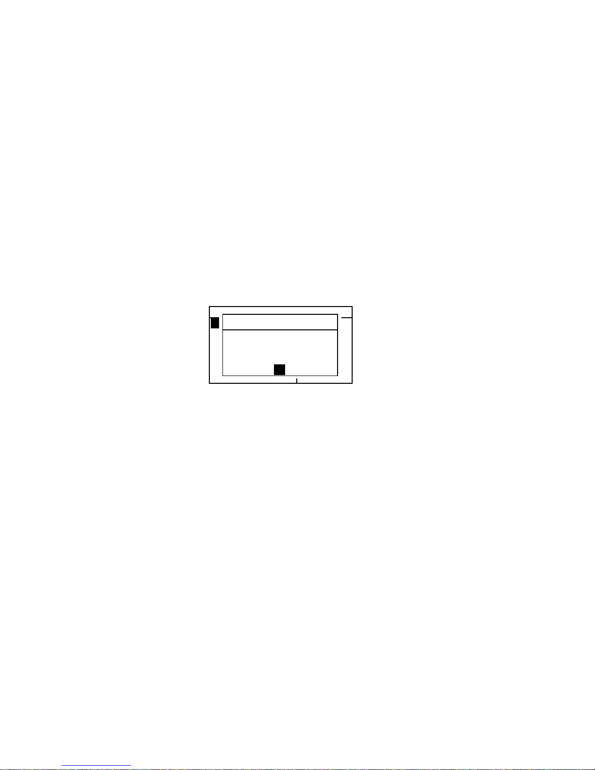
CHAPTER FOUR
4-24
Load Factory Defaults
The instrument can be reset to its original state whenever
required. All configuration settings and function options are set
to the factory defaults. Restoring the defaults also clears all
stored standard s, samples, and ta g data in the instru ment.
To initiate a factory default reload:
1. Unplug the AC Adapter (if connected) and press the power
switch to Off. Simultaneously press and hold the Tab
Down key @ and Main Menu key
%.
2.
Press the power switch to On. The X-Rite logo
momentarily appears followe d by
Factory Defaults,
Settings have been restored
. Press the Enter #
key to clear the message dialog.
–MAIN MENU–
QA
Analyze
Compare
Strength
Opacity
^
X—Rite
393
——————
XXXX
******
Factory Defaults
Settings have
been restored.
OK
Page 52
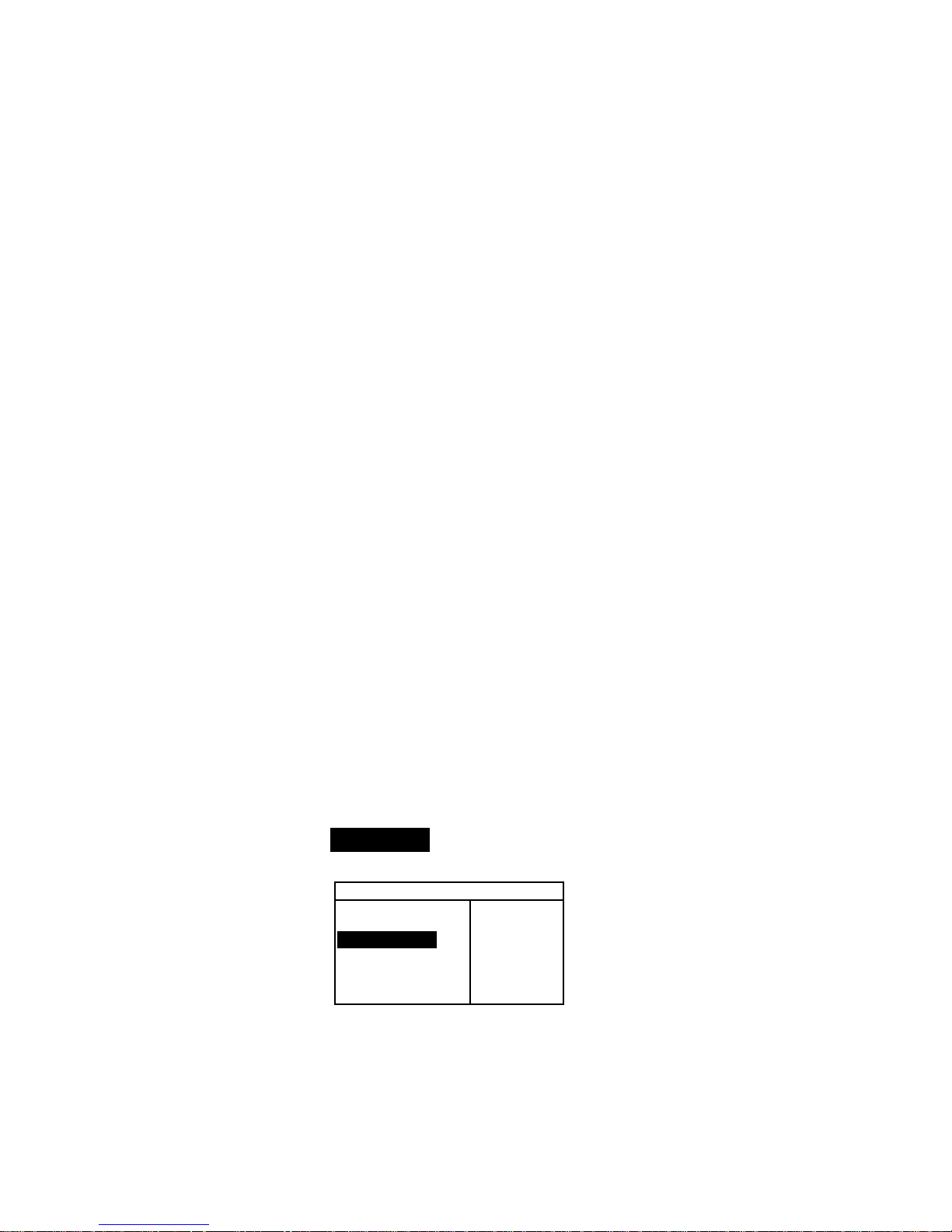
962/964
SPECTROPHOTOMETER
5-1
5. Instrument Operation
Standards 5-1
Projects 5-11
QA Mode 5-15
Strength 5-24
Opacity 5-26
Analyze 5-28
Compare 5-29
Run Job (964only) 5-30
Standards
The standards function accesses the Edit Standard menu. From
this menu, standard data can be measured or manually entered,
and specific tolerances and shade sort options can be set for
each standard.
The standards serve as approved references against which your
sample measurements are evaluated, using QA, Strength,
Opacity, or Analyze functions.
Standards can also be downloaded to the instrument from an
X-Rite software package, such as X-RiteColor® Master. Then,
after sample measurements are performed, data is uploaded to
the software package, where it is analyzed.
The main Standard screen gives the status of the standard last
selected.
To open the Edit Standard menu:
1. Repeatedly press the Tab Down @ key to highlight
Standards. Press the Enter key # to access the Edit
Standards Menu.
–MAIN MENU–
↑
Calibrate
Standards
Projects
Run Job
Configuratio
X—Rite
964
——————
XXXX
******
Selecting Standard Number
The standard number allows you to select existing standards for
editing, or the next available standard location for entering a new
standard.
Page 53

CHAPTER FIVE
5-2
The Standard Entry field displays “Empty”, when an available
standard location is selected. This is the location you would use
to enter a new standard.
To access a new or existing standard location:
1. Use the Tab keys $@ to highlight the standard # in the Edit
Standard field.
Edit Standard : 1
Std Entry:Measured
Std Name :Blue Sample
Tolerances...
Shade Sort Opts...
Std Lock : Unlocked
Delete THIS Std...
2. Press the Enter key # to page to a new or existing standard
location.
NOTE: You can go to a specific standard by holding down the Enter
key # until the Enter Std Number menu appears, and selecting the
number through the editor. This provides a convenient method of
selecting a specific standard when many standards exist in the
database.
Entering Standard Data
Depending on how data was input, the sta nda rd entry fi el d
displays as Measured, Manual, or Downloaded. Measured
appears when the instrument was used to measure the sample.
Manual displays when data values are manually entered into the
instrument using the alphanumeric editor. Download indicates
that the standard data was downloaded to the instrument from
an X-Rite software program, such as X-RiteColor® Master.
To access the standard entry menu:
1. Use the Tab keys $@ to highlight Std Entry.
Edit Standard : 1
Std Entry:Empty
Std Name :
Tolerances...
Shade Sort Opts...
Std Lock :Unlocked
2. Press the Enter key # to access the Standard Entry menu.
Measure Std : 1
< Measure Standard>
L*a*b*
D65/10
....
.
.
.
...
L* 0.00
a* +0.00
b* +0.00
The field indicates the
status of the standard
(measured, manual,
downloaded, or empty)
Page 54
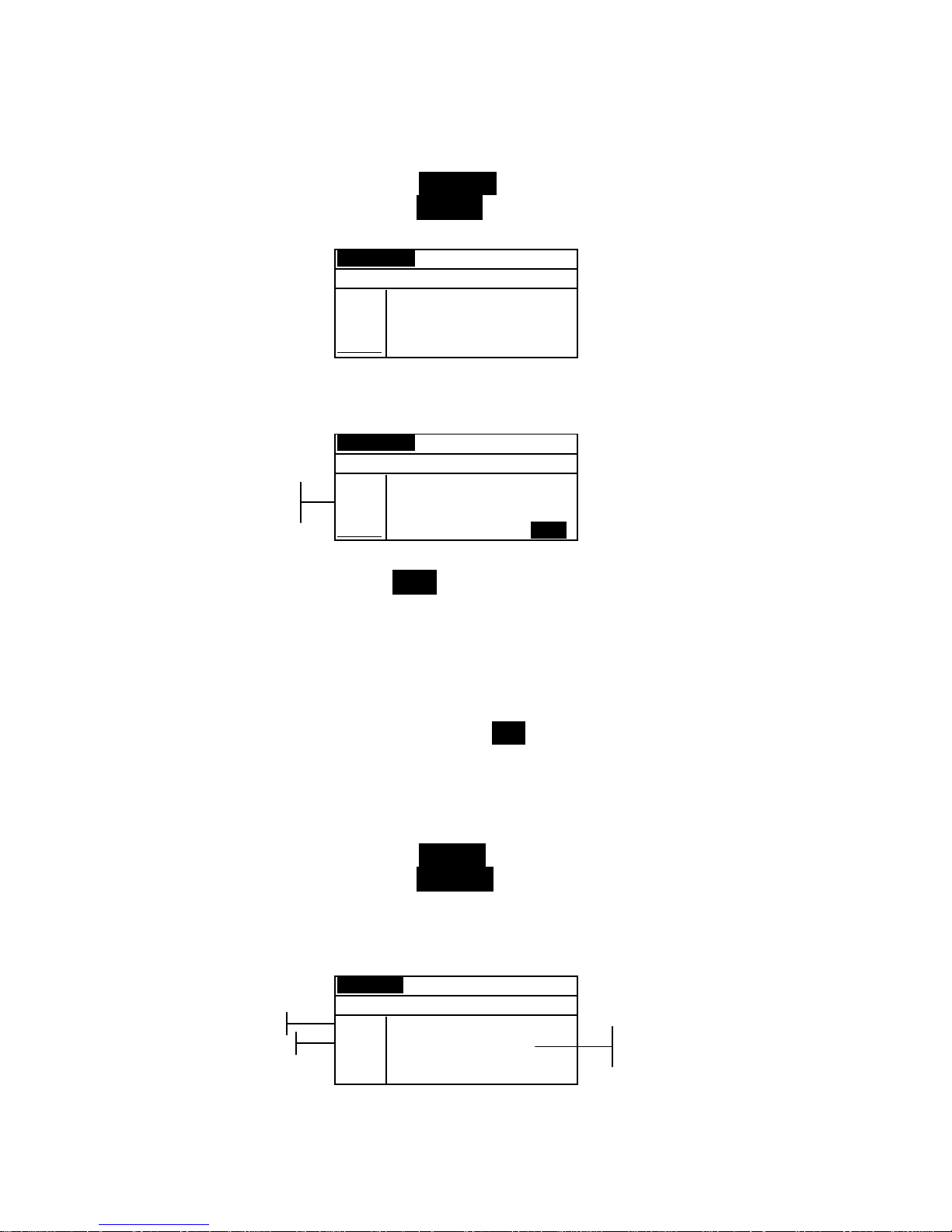
INSTRUMENT OPERATION MODES
5-3
Measuring a Standard
1. Make sure Measure appears in the upper left corner of the
display. If Manual appears, press the Enter key # to
toggle to Measure.
Measure Std : 1
< Measure Standard>
L*a*b*
D65/10
....
.
.
.
...
L* 0.00
a* +0.00
b* +0.00
2. Position the instrument on the standard and take the
reading. Release the instrument when
Measurement Done
is displayed.
Measure Std : 1
< Measurement Done>
L*a*b*
D65/10
....
.
.
.
...
L* 23.30
a* –0.25
b*–28.03
SAVE
3. Retake the measurement if necessary, or press the Enter key
# with Save highlighted to store measurement. The screen
automatically advances to the next “empty” standard.
4. Continue with additional measurements.
Locked Standards
When attempting to measure a standard with a locked standard
selected, a
Standard Locked: Create New Standard?
message appears. Select Yes if you want to create a new
standard and press the Enter key #. The standard must be
unlocked if you want to overwrite the existing data. Refer to
Unlocking/Locking Standards later in this section.
Manually Entering Color Data
1. Make sure Manual appears in the upper left corner of the
display. If Measure appears, press the Enter key # to
toggle to Manual.
2. Use the Tab keys $ @ to highlight the color space parameter.
Press the Enter key # to select the desired color space.
Manual Std : 1
< Enter Color Data>
XYZ
A/2
Next
X 0.00
Y 0.00
Z 0.00
SAVE
3. Use the Tab keys $ @ to highlight the illum/obs parameter.
Press the Enter key # to select the desired illum/obs.
Color data
parameters
Color space
attributes
Color space
Ilum/Obs
Page 55

CHAPTER FIVE
5-4
4. Use the Tab keys $ @ to highlight the desired color space
attribute. Press the Enter key # to open Edit Color
Data
menu.
5. Use the Tab keys $@ to choose the desired digit (arrows
above and below designate the selection). Press the Enter
key # to access the alphanumeric editor.
Edit Color Data:
CLEAR
↓
+000.0000
↑
Save & Exit
NOTE: Positioning the arrows above and below + or – and pressing
the Enter key # toggles between the two symbols.
6. Use the Tab keys $@ to highlight the desired number and
press the Enter # key to exit editor.
7. Continue with additional digit edits if required.
8. When editing is completed, use the Tab keys $@ to
highlight
Save & Exit and press the Enter # key.
9. Continue with additional attribute editing for the selected
color space.
10. When all attributes have been edited for the selected color
space, highlight Save and press the Enter key #.
11. If additional color space editing is required, repeat Steps 2
through 11. Up to 10 manual sett i ngs can be defined for
each standard.
NOTE: Highlighting Next and continually pressing the Enter key #
pages through the color space data that you have set.
Entering Standard Name
The standard name can consist of up to 20 characters, with the
first 10 displaying on the View Standard menu. The name is
entered using the alphanumeric editor.
To access standard name menu:
1. Use the Tab keys $@ to highlight Std Name.
Page 56
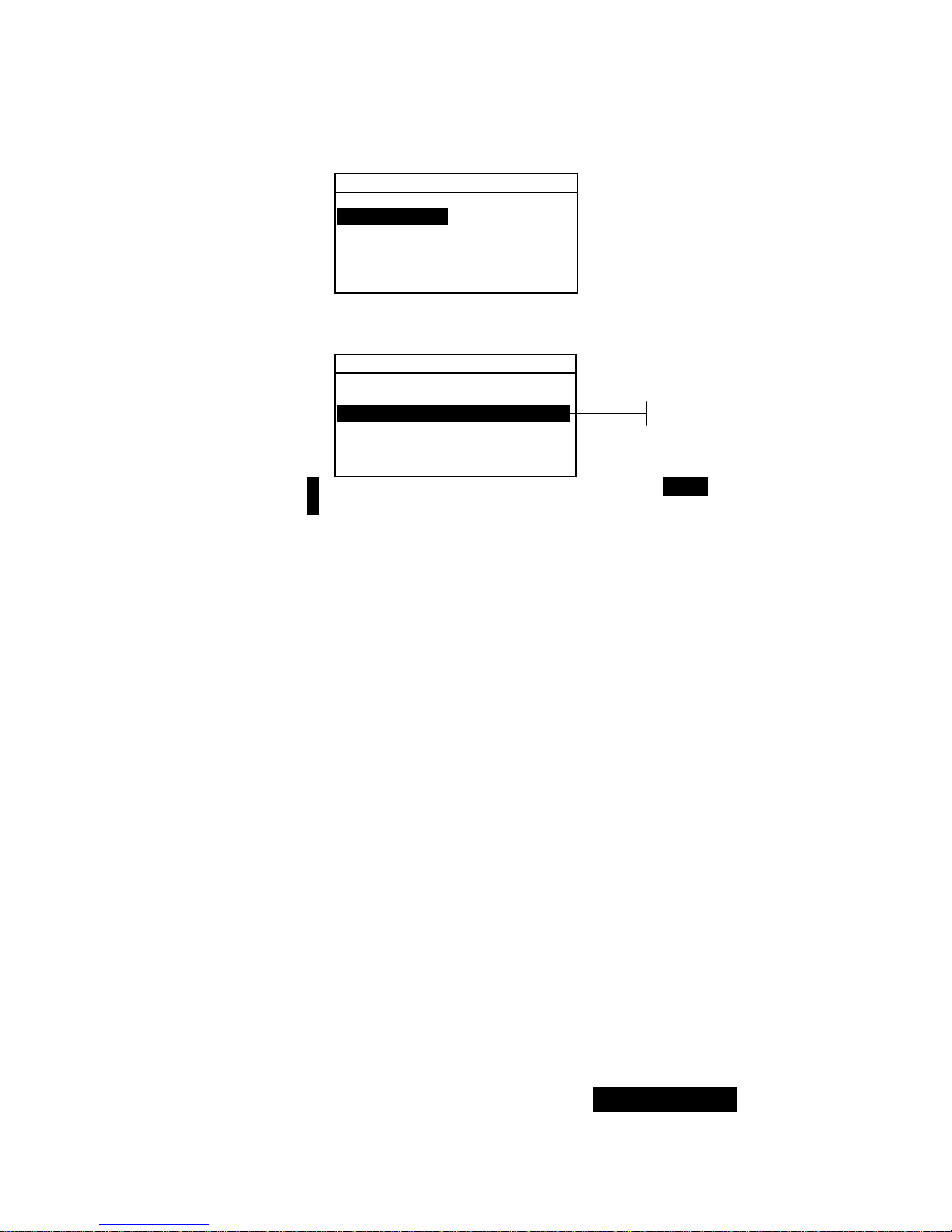
INSTRUMENT OPERATION MODES
5-5
Edit Standard : 1
Std Entry:Measured
Std Name :
Tolerances...
Shade Sort Opts...
Std Lock :Unlocked
Delete This Std...
2. Press the Enter key # to access the Edit Standard
Name
menu.
Edit Standard Name
CLEAR
↓
o
↑
Save & Exit
NOTE: To quickly remove a name, highlighting CLEAR and press the
Enter key #.
3. Use the Tab keys $@ to highlight the name entry field.
4. Use the Tab keys $@ to choose the desired character
location (arrows above and below designate the selection).
Press the Enter key # to access the alphanumeric editor.
5. Press the Enter key # again to quickly page through
groups of letters, symbols, and numbers.
6. Use the Tab keys $@ to highlight the desired character and
press the Enter # key to exit editor.
7. Continue with additional character edits.
8. When editing is completed, use the Tab keys $@ to
highlight
Save & Exit and press the Enter # key.
Setting Tolerance Limits
The tolerance limit is the maximum allowable difference from
the standard color values that is considered acceptable. The
tolerances are used to test your sample’s acceptability by
displaying a pass or fail signal, based on the entered limits.
Plus and minus limits can be set symmetrically or individually
for L*a*b*, L*C*h°, L*u*v*, Lab, RGB, XYZ and Yxy
attributes. Pass/fail indication appears in QA and Strength
functions when set.
To access tolerance entry menu:
1. Use the Tab keys $@ to highlight Tolerances... .
Name entry
Page 57
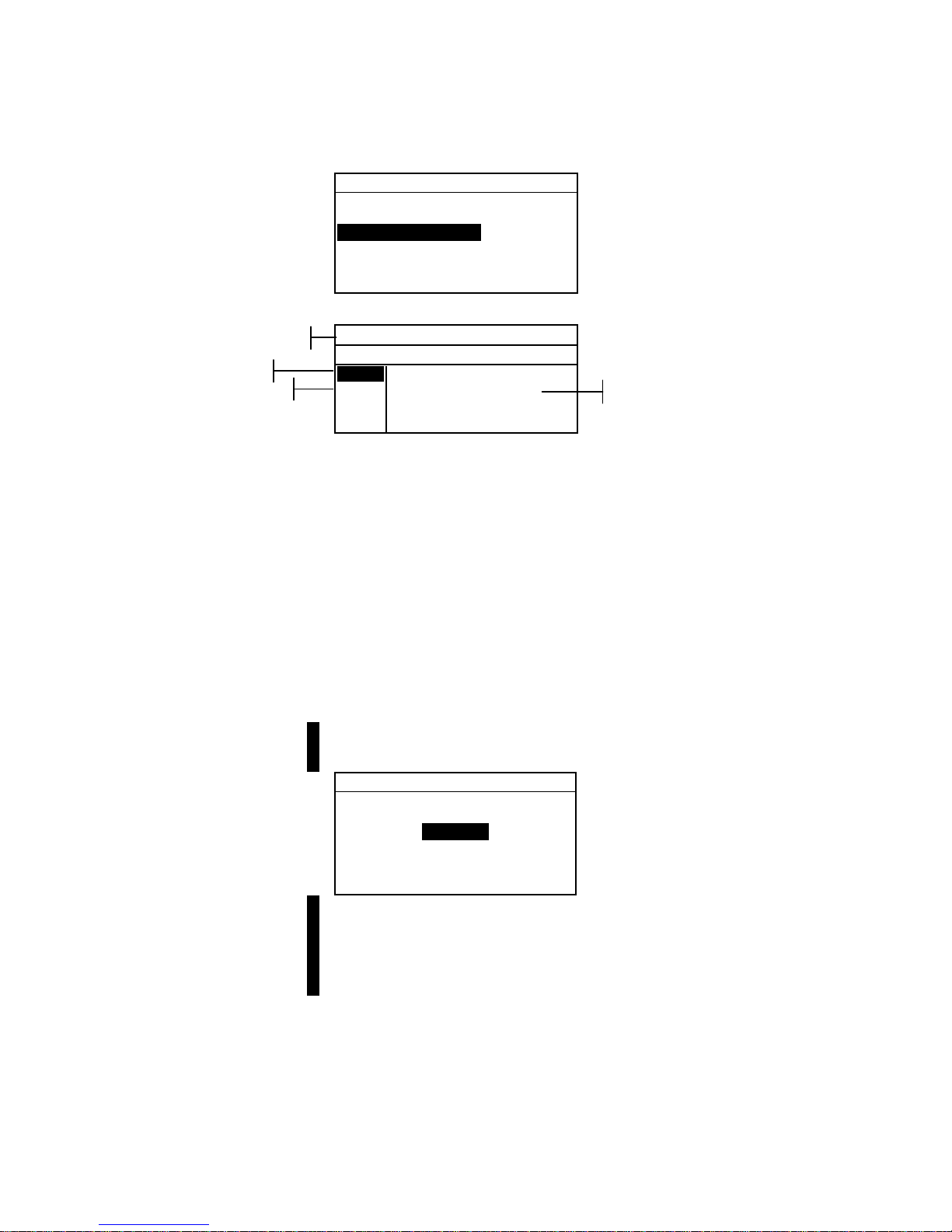
CHAPTER FIVE
5-6
Edit Standard : 1
Std Entry:Empty
Std Name :
Tolerances...
Shade Sort Opts...
Std Lock :Unlocked
Delete THIS Std...
2. Press the Enter key # to access the tolerance entry menu.
± Tol: Std : 1
< Set Equal Limits>
L*a*b*
D65/10
Next
ΔL* ±0.00
Δa* ±0.00
Δb* ±0.00
SAVE
3. Use the Tab keys $ @ to highlight the Tolerance type. Press
the Enter key # to select the desired type.
4. If entering different plus and minus values f or L*a * b* ,
L*C*h°, etc., use the Tab keys $ @ to highlight the
plus/minus symbol in the upper left of the display. Press
the Enter key # to page through
±, +, or – limit type.
5. Use the Tab keys $ @ to highlight the illum/obs parameter.
Press the Enter key # to select desired illum/obs.
6. Use the Tab keys $ @ to highlight the desired tole rance ty pe
attribute. Press the Enter key # to open
Enter
Symmetric Tol
menu.
NOTE: Depending on Limit Type selection, Plus or Minus could
appear in place of Symmetric.
Enter Symmetric Tol:
CLEAR
↓
0.0000
↑
Save & Exit
NOTE: “Standard cannot be changed” appears in the display
when attempting to edit attributes with the standard locked. Refer to
Locking/Unlocking Standard later in this section for additional
information. Press the Enter key # to clear the message.
7. Use the Tab keys $@ to choose the desired digit (arrows
above and below designate selection). Press the Enter key
# to access the alphanumeric editor.
8. Use the Tab keys $@ to highlight the desired number and
press the Enter # key to exit the editor.
9. Continue with additional digit edits if required.
Ilum/Obs
Tolerance Limit Type
Tolerance Type
Tolerance type attributes
Page 58
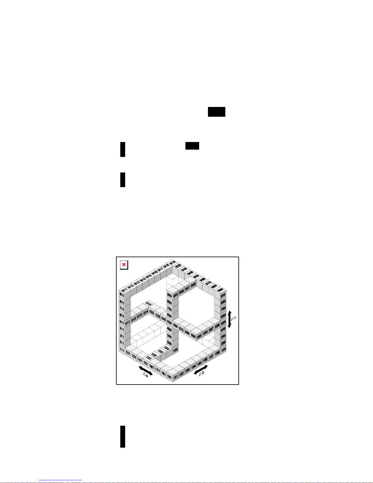
INSTRUMENT OPERATION MODES
5-7
10. When editing is completed , use the Tab keys $@ to
highlight Save & Exit and press the Enter # key.
11. Continue with add itional attribute editing for the selected
tolerance type.
12. When all attributes have been edited for the selected
tolerance type, highlight Save and press the Enter key #.
13. If additional tolerance type editing is required, repeat Steps
2 through 12.
NOTE: Highlighting Next and continually pressing the Enter key #
pages through the tolerances that you have set.
Setting Shade Sort Options
NOTE: The Shade Sort option does not appear for a standard with
manually entered data.
The shade sort size is based on the dimensions placed on the
color space attributes. The value represents a three-dimensional
box in space. These boxes are layered nine deep on each axis
and at the center is the 555 reference bo x. T his bo x rep rese nt s
your reference color. The value in the L*, a*, and b* fields
determine the reference box size. A smaller value is entered for
a tighter tolerance. Values range from .01 to 9.99
The shade sort range determines the range of the 555 shade tag
boxes to be used and displayed. The range can be set from 1 to
9 in the three dimensional space.
The 555 indication appears on the QA mode when set.
NOTE: The Shade Sort options cannot be edited if the standard is
locked. Refer to Locking/Unlocking Standard later in this section for
additional information
Page 59

CHAPTER FIVE
5-8
To access the shade sort options menu:
1. Use the Tab keys $@ to highlight Shade Sort Opts... .
Edit Standard : 1
Std Entry:Measured
Std Name :
Tolerances...
Shade Sort Opts...
Std Lock :Unlocked
Delete THIS Std...
2. Press the Enter key # to access the size/range setup menu.
Shade Sort Size Editing
1. Make sure Size appears in the upper left corner of the
display. If Range appears, press the Enter key # to toggle
to Size.
Size Std : 1
< Set 555 Sort Size>
L*a*b*
D65/10
L* 1.00
a* 1.00
b* 1.00
SAVE
2. Select the desired color space and illum/obs.
3. Use the Tab keys $ @ to highlight the desired color space
attribute. Press the Enter key # to open the
Edit Sort
Size menu.
Edit Sort Size
CLEAR
↓
1.00
↑
Save & Exit
4. Use the Tab keys $@ to choose the desired digit (arrows
above and below designate the selection). Press the Enter
key # to access the alphanumeric editor.
5. Use the Tab keys $@ to highlight the desired number and
press the Enter # key to exit the editor.
6. Continue with additional digit edits if required.
7. When editing is completed, use the Tab keys $@ to
highlight
Save & Exit and press the Enter # key.
8. Continue with additional attribute editing for the selected
color space.
9. When all attributes have been edited for the selected color
space, highlight Save and press the Enter key #.
Color space
attributes
Page 60
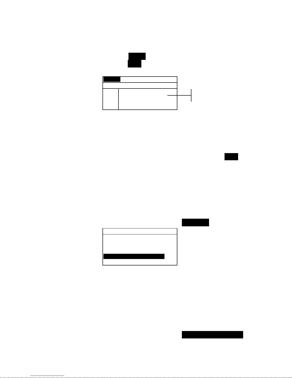
INSTRUMENT OPERATION MODES
5-9
Shade Sort Range Editing
1. Make sure Range appears in the upper left corner of the
display. If Size appears, press the Enter key # to toggle
to Range.
Range Std : 1
< Set 555 Sort Range>
L*a*b*
D65/10
L* 1 to 9
a* 1 to 9
b* 1 to 9
SAVE
2. Select the desired color space and illum/obs.
3. Use the Tab keys $ @ to highlight the desired lower or
upper sort range component.
4. Repeatedly press the Enter key # to select the desired
range value.
5. Continue with additional component editing.
6. When all components have been edited, highlight Save
and press the Enter key #.
Locking/Unlocking Standard
All measured and manually entered standards are initially set as
locked. A locked standard cannot be deleted or edited. The
“locked” status of the standard can be changed whenever
desired. Downloaded standards cannot be unlocked.
To change the locked status of a standard:
1. Use the Tab keys $@ to highlight Std Lock.
Edit Standard : 1
Std Entry:Measured
Std Name :
Tolerances...
Shade Sort Opts...
Std Lock :Unlocked
Delete THIS std...
2. Press the Enter key # to toggle between Locked and
Unlocked. The “Delete THIS std” option only appears for
an unlocked standard.
Deleting the Standard
This option deletes the current standard selected. While the
standard number remains, all related data is deleted. You can
then use the location to add a new standard.
To delete the current standard:
1. Use the Tab keys $@ to highlight Delete THIS Std....
Sort range
components
Page 61
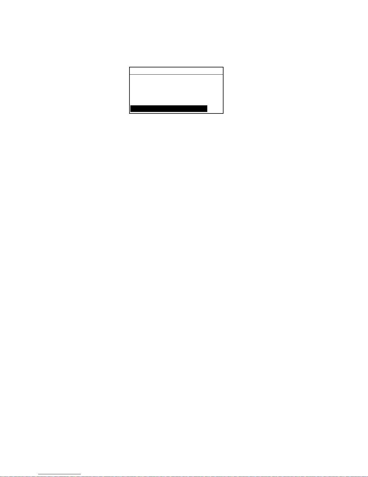
CHAPTER FIVE
5-10
Edit Standard : 1
Std Entry:Measured
Std Name :
Tolerances...
Shade Sort Opts...
Std Lock :Unlocked
Delete THIS std...
2. Press the Enter key # to delete the current standard.
Page 62
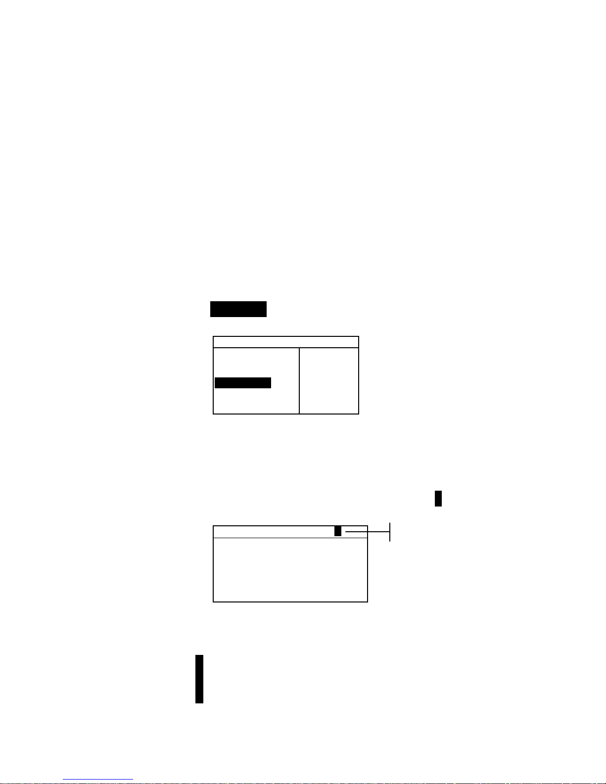
INSTRUMENT OPERATION MODES
5-11
Projects
The projects function is used to access the View Project menu.
From this menu, project names and standard links can be
created and edited and new projects added.
A project maintains a group of standards from which the
instrument selects the closest color for comparison of measured
samples.
Projects help you organize your standards. For example, a
project can represent a customer that has several standard
colors for a particular product line.
To open the View Project menu:
• Repeatedly press the Tab Down @ key to highlight
Projects. Press the Enter key # to access the View
Project Menu.
–MAIN MENU–
↑
Calibrate
Standards
Projects
Run Job
Configuratio
X—Rite
964
——————
XXXX
******
Selecting Project Number
The project number is used to page to a specific project location
if more than one project exists in the database.
To access a new or existing project location:
1. Use the Tab keys $@ to highlight the project # in the View
Project field.
View Project : 1
Proj Standards
Proj Name:
Proj Lock: Unlocked
Add New Project
Delete This Project
2. Press the Enter key # to page to the project location. One
is the only location that can be selected when no projects
exist in the database.
NOTE: You can go to a specific project by holding down the Enter
key # until the Enter Proj Number menu appears, and selecting
the number through the editor. This provides a convenient method of
selecting a specific project when many projects exist in the database.
Current project location
Page 63
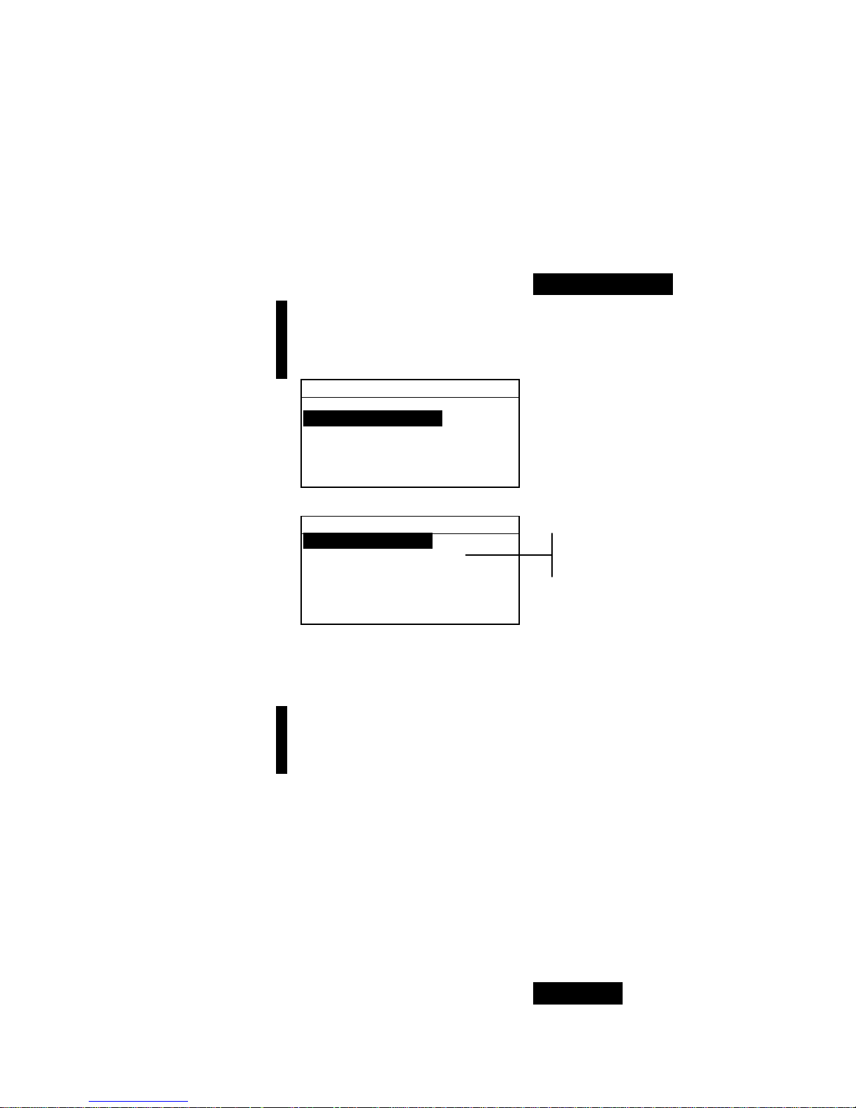
CHAPTER FIVE
5-12
Assigning Standards to a Project
The project standard field is used to assign standards that exist
in the database to the selected project. Standards can be shared
between projects. A total of 300 standards can be assigned to
one project.
To assign standards to a project:
1. Use the Tab keys $@ to highlight Proj Standards.
NOTE: If no standards are assigned to the current project, the “No
stds in this project. Using all standards” message
appears. Press any key to clear the message and continue with
assigning standards.
View Project : 1
Proj Standards
Proj Name:
Proj Lock: Unlocked
Add New Project
Delete This Project
2. Press the Enter key # to access the Select Standards menu.
Select Standards
1: Standard A
> 2: Standard B
3: Standard C
> 4: Standard D
5: Standard E
6: Standard F
3. Use the Tab keys $@ to highlight the standard to assign.
4. Press the Enter key # to toggle the standard active or
inactive. The “>” indicates the standard is assigned.
NOTE: “Project is Locked” appears in the display when
attempting to change the status of a standard when the project is
locked. Refer to Locking/Unlocking Projects later in this section for
additional information. Press the Enter key # to clear this if it occurs.
5. Continue with additional standard selections.
6. After selections are complete, press the Escape key ! to
save and exit.
Entering Project Name
The project name can consist of up to 20 characters with the first
10 displaying in the View Project menu. The name is entered
using the alphanumeric editor.
To access project name menu:
1. Use the Tab keys $@ to highlight Proj Name.
A
rrow indicates
selected standard
Page 64

INSTRUMENT OPERATION MODES
5-13
View Project : 1
Project Standards
Proj Name:
Proj Lock:Unlock
Add New Project
Delete This Project
2. Press the Enter key # to access the Edit Project Name
menu.
NOTE: “Project is Locked” appears in the display when
attempting to enter name with the project locked. Refer to
Locking/Unlocking a Project later in this section for additional
information. Press the Enter key # to clear message.
Edit Project Name
CLEAR
↓
o
↑
Save & Exit
3. Use the Tab keys $@ to highlight the name entry field.
4. Use the Tab keys $@ to choose the desired character
location (arrows above and below designate selection).
Press the Enter key # to access the alphanumeric editor.
5. Press the Enter key # again to quickly page through
groups of letters, symbols, and numbers.
NOTE: If editing a name, highlighting CLEAR and pressing the Enter
key # will quickly clear the name field.
6. Use the Tab keys $@ to highlight the desired character and
press the Enter # key to exit the editor.
7. Continue with additional character edits.
8. When editing is completed, use the Tab keys $@ to
highlight
Save & Exit and press the Enter # key.
Locking/Unlocking Project
A locked project cannot be edited. The “locked” status of the
project can be changed whenever desired.
To change the locked status of a project:
1. Use the Tab keys $@ to highlight Proj Lock.
Name entry
Page 65
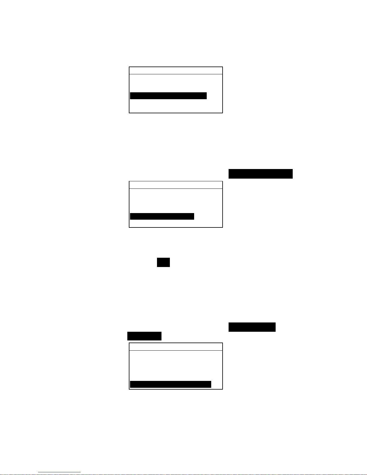
CHAPTER FIVE
5-14
View Project : 1
Proj Standards
Proj Name:
Proj Lock:Unlocked
Add New Project
Delete This Project
2. Press the Enter key # to toggle between Locked and
Unlocked.
Add New Project
The “Add New Project” item adds a new project to the database.
To add a new project:
1. Use the Tab keys $@ to highlight Add New Project.
View Project : 1
Proj Standards
Proj Name:
Proj Lock:Unlocked
Add New Project
Delete This Project
2. Press the Enter key # to open the Add New Project
menu.
3.
Add a new project? appears. Use the Tab keys $@ to
highlight Yes and press the Enter key #. A new project
number is added to the View Project field.
Deleting the Project
This option deletes the current project selected and samples.
Standards that are assigned to the project are not deleted.
To delete the current project:
1. Use the Tab keys $@ to highlight Delete This
Project.
View Project : 1
Proj Standards
Proj Name:
Proj Lock:Unlocked
Add New Project
Delete This Project
2. Press the Enter key # to delete the current project.
Page 66

INSTRUMENT OPERATION MODES
5-15
QA (Quality Assurance)
The QA measurement function can be used in conjunction with
an X-Rite quality assurance software package, such as
X-RiteColor® Master program. Sample measurements are
compared to stored standards and the results displayed. Stored
measurement data can then be uploaded to the software
program for further analysis. The measurement results
displayed depend on how the instrument configuration is set.
Measurement results can display as measured or color
difference compared to a standard. Difference data can have
pass/fail tolerancing applied along with 555 shade sort. This
section covers all the functions available in the QA mode.
To access the QA function:
1. Use the Tab keys $@ to highlight QA.
–MAIN MENU–
QA
Analyze
Compare
Strength
Opacity
↓
X—Rite
964
——————
XXXX
******
2. Press the Enter key # to access the QA function.
Proj 1: PROJECT A
Std 1: STANDARD A
Sample: < Last Meas>
L*a*b*
D65/10
....
.
.
.
...
ΔL* +0.05
L* 88.25 Δa* —0.03
a* —4.71 Δb* —0.14
b*+36.64 ΔE* 0.16
Project Name
Standard Name
Project Location
Standard Location
This field always displays
<Last Meas> when samples
are not stored. When
samples are stored, a
sample # and time stamp is
displayed.
Accesses
Sample Tools
Sample difference values or
words appear indicating
color direction compared to
the current standard.
This area displays sample
measurement values.
Pass/Fail and 555 Shade
Sort indication appears
here when they are
activated.
Page 67

CHAPTER FIVE
5-16
Selecting a Project
The instrument defaults to Proj 1 until a project is downloaded
or manually entered. When using multiple projects, you must
select the correct location before measuring a sample. The auto
standard function does not recognize standards across multiple
projects.
To select a project:
1. Use the Tab keys $@ to highlight Proj #.
Proj 1: PROJECT A
Std 1: STANDARD A
Sample: < Empty>
L*a*b*
D65/10
....
.
.
.
...
2. Continually press the Enter key # to page through the
available projects, or hold do wn the Ente r key # and select
a specific project from the editor.
NOTE: Highlighting the project name and pressing the Enter key #
accesses the View Project menu. Refer to Projects Mode covered
earlier in this section for information on this mode.
Selecting a Standard
A standard must be manually selected when the Auto Std
option is turned off in the configuration menu . Only standards
assigned to the selected project appear in this field. If no
projects are used, any standard in the database can be selected.
To select a standard:
1. Use the Tab keys $@ to highlight Std #
Proj 1: PROJECT A
Std 1: STANDARD A
Sample: < Empty>
L*a*b*
D65/10
....
.
.
.
...
2. Continually press the Enter key # to page through the
available standards, or hold down the Enter key # and
select a specific standard from the editor. A “flag” icon
appears next to standards that have manually entered data.
NOTE: Highlighting the standard name and pressing the Enter key #
accesses the View Standard menu. Standard information can only be
viewed from this menu. Refer to Standards Mode covered earlier in
this section for information on this mode.
Page 68

INSTRUMENT OPERATION MODES
5-17
Pass/Fail Operation
The Pass/Fail function displays PASS or FAIL for a sample on the
instrument screen, based on the tolerances assigned to the standard.
A “green” or “red” light also illuminates, indicating the sample’s
acceptability. The Pass/Fail option must be activated in the
Instrument Configuration and tolerances set for the standard.
To perform a pass/fail measurement:
1. Select project location (if used) as discussed earlier.
2. Select the standard location if the auto standard selection is
not activated in configuration. Measure the sample.
Proj 1: PROJECT A
Std 2: STANDARD B
Sample: #1 11:28
L*a*b*
D65/10
....
.
.
.
...
ΔL* +0.35
Δa* –0.15
Δb* +0.15
ΔE 0.41
555 Shade Sort Operation
The 555 Shade Sort function displays a three-digit number for
the sample on the instrument screen, based on the shade size
and shade range. Pass/Fail operation can also be used in
conjunction with Shade Sort if required. The Shade Sort option
must be activated in the Instrument Configuration and the size
and range set for the standard.
To perform a shade sort measurement:
1. Select the project location (if used) as discussed earlier.
2. Select standard location if the auto standard selection is not
activated in the configuration. Measure the sample.
Proj 1: PROJECT A
Std 2: STANDARD B
Sample: #1 11:28
L*a*b*
D65/10
....
.
.
.
...
ΔL* +0.35
Δa* –0.15
Δb* +0.15
ΔE 0.41
PASS
Acceptance
indication (pass
or fail
)
Time stamp for
stored sample
Time stamp for
stored sample
Acceptance
indication with
shade tag
PASS
565
Page 69
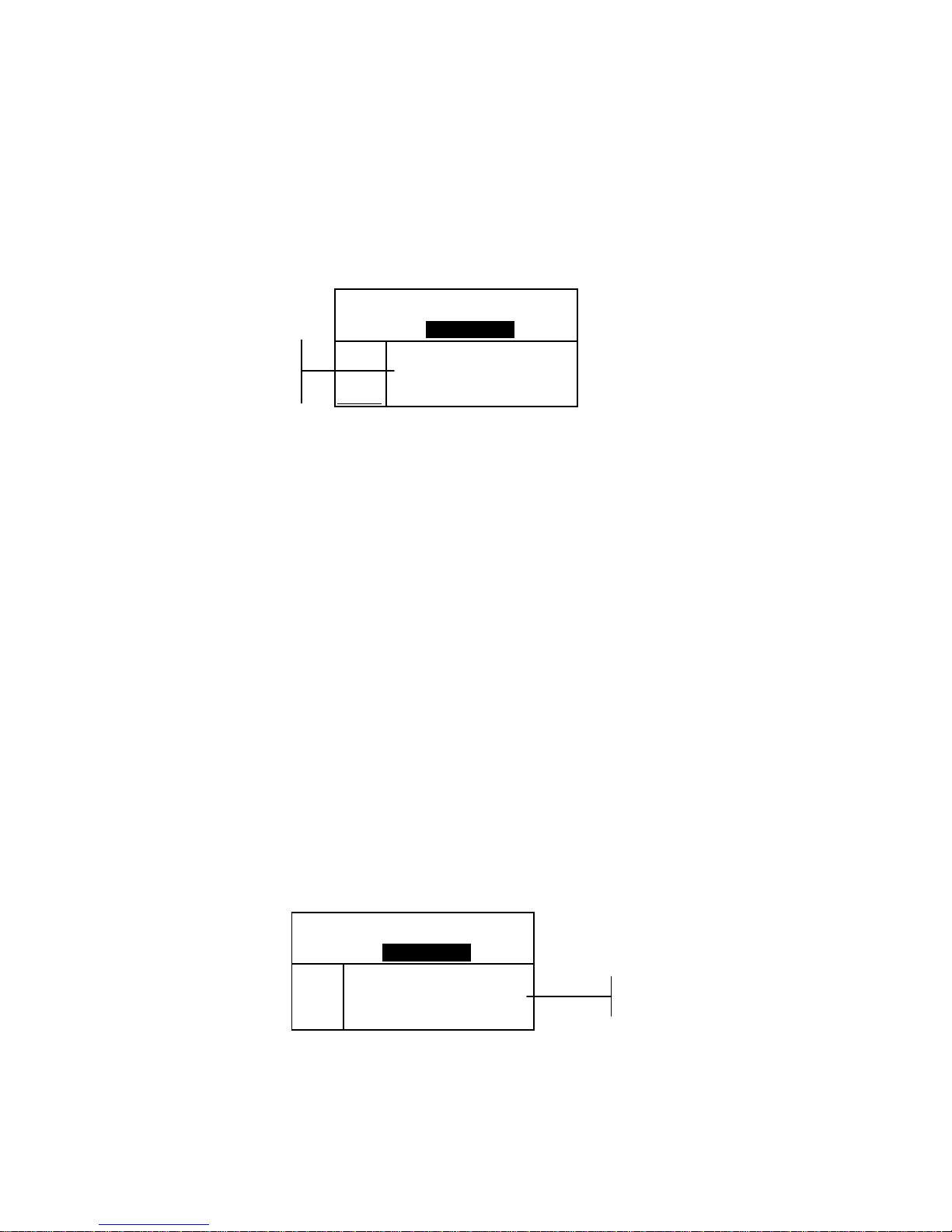
CHAPTER FIVE
5-18
Shade Sort Out of Range Indication
If an up arrow or a down arrow appears in the place of a shade
sort number, this indicates that the number is out of range. The
way the arrow is pointing indicates the failure direction. An up
arrow indicates above and a down arrow indicates below.
Proj 1: PROJECT A
Std 2: STANDARD B
Sample: #2 11:35
L*a*b*
D65/10
....
.
.
.
...
ΔL*–17.36
Δa* +4.24
Δb*+30.16
ΔE 35.05
Display Difference Indication
The instrument can display color differences numerically
(default setting) or as a verbal description, depending on the
setting of the Difference Display option in Configuration. When
delta words are used, the “L*” attribute for L*a*b* or L*C*H*
displays as “
Lighter” or “Darker” from the standard. The
“a*” and “b*” attributes for L*a*b* and the “H*” (hue) attribute
for L*C*H* display as “>>
Red”, “>>Grn”, “>>Blu”, or
“>>
Yel.” This is an indication of what color direction the
attribute is towards. For L*C*H*, the “C*” (chroma) attribute
will display as “
Brighter” or “Duller.” Words only appear
for L*a*b*, L*C*h°, and Lab (Hunter) color space selections.
Words will not display for an attribute that is less than 1/7
th
of
the ΔE value. A value less than this amount is considered
insignificant compared to the total difference.
If the delta value for any attribute is greater than “10.00”, the
display changes to numeric values.
The Difference Display option must be set to “Words” in the
Instrument Configuration.
Proj 1: PROJECT A
Std 2: STANDARD B
Sample: #3 12:05
L*a*b*
D65/10
...
.
...
.
.
.
Darker
>> Red
>> Yel
ΔE 0.86
Storage Operation
When the storage function is activated in the instrument
configuration, sample measurements are saved to the database
with a number and a time stamp. The instrument provides a
FAIL
↑6↓
Failure
indication and
direction
Direction of
color difference
PASS
455
Page 70

INSTRUMENT OPERATION MODES
5-19
large amount of RAM for storing samples and standards. A
combined total of more than 3,000 can be stored in the
database.
To view stored measurements:
1. Select the project location (if used) as discussed earlier.
2. Use the Tab keys $@ to highlight the sample number and
time stamp.
3. Continually press the Enter # key to page through stored
samples, or hold down the Enter key # and select a
specific sample from the editor. To delete or transmit the
stored sample, refer to Sample Tools.
Proj 1: PROJECT A
Std 1: STANDARD A
Sample: #9 9:51
L*a*b*
D65/10
....
.
.
.
...
ΔL* +0.05
L* 88.25 Δa* —0.03
a* —4.71 Δb* —0.14
b*+36.64 ΔE* 0.16
NOTE: Sample numbers may not appear in a consecutive order if
multiple projects are used. The instrument numbers the samples in the
order that they are measured, and only samples associated with the
current project are displayed.
Sample number
and time stamp
Page 71

CHAPTER FIVE
5-20
Measurement Averaging
When the averaging function is activated, all modes (except
calibration) require multiple measurements per sample. The
number of measurements is set in the instrument configuration.
Measurements are typically taken at various locations on a
sample to achieve average data values. Averaging should be
used when measuring non-uniform samples, textured materials,
and any dark or high chroma colors.
To perform an averaging measurement sequence:
1. Select project location (if used) as discussed earlier.
2. Select the standard location if the auto standard selection is
not activated in configuration.
3. Position the instrument on the first area of the sample and
take measurement. Sample data appears when the
instrument is held down and averaged data appears when
the instrument is lifted.
NOTE: Pressing the Escape key ! during averaging aborts the
sequence and removes all measurements averaged to that point.
Proj 1: PROJECT A
Std 2: STANDARD B
Average: 1 of 3
L*a*b*
D65/10
....
.
.
.
...
ΔL* +0.35
L* 94.10 Δa* –0.15
a* +0.91 Δb* +0.15
b* –3.59 ΔE 0.41
4. Continue with additional measurements as required to
fulfill averaging sequence.
Sample Database Tools
The Sample Database Tools menu allows you to transmit data
to a computer or printer and delete stored sample data. If the
storage feature is not used, only the current sample can be
transmitted from this menu.
To access the tools menu:
1. Select the project location (if used) and store sample as
discussed earlier.
2. Use the Tab keys $@ to highlight Sample.
Proj 1: PROJECT A
Std 1: STANDARD A
Sample: #9 9:51
L*a*b*
D65/10
....
.
.
.
...
ΔL* +0.05
L* 88.25 Δa* —0.03
a* —4.71 Δb* —0.14
b*+36.64 ΔE* 0.16
Indicates the first
measurement of three
required
Page 72

INSTRUMENT OPERATION MODES
5-21
3. Press the Enter # key to open the Tools menu.
Tools – Sample 9
Transmit This Sample
Transmit Proj Sample
Transmit All Samples
Delete This Sample
Delete Proj Samples
Delete All Samples
Transmit This Sample
Transmits the current sample data out the serial port.
Transmit Proj Sample
Transmits all samples that exist in the current project.
Transmit All Samples
Transmits all samples stored in the instrument.
Delete This Sample
Deletes the current sample from the database.
Delete Proj Samples
Deletes all samples attached to the current project.
Delete All Samples
Deletes all samples stored in the database.
4. Use the Tab keys $@ to highlight the desired tools option
and press the Enter key #.
5. Use the Tab keys $@ to highlight
Yes and press the Enter
key # to initiate the selected tools option.
Viewing the Reflectance Graph
The instrument can display reflectance graphs for the standard
and sample at the same time. Reflectance values (actual or
difference) are displayed in 10nm increments, from 400 to 700
nanometers.
Measurements can be taken with the reflectance graph
displayed in Analyze and Compare mode.
To view a reflectance graph:
1. Use the Tab keys $@ to highlight the reflectance curve.
Proj 1: PROJECT A
Std 1: STANDARD A
Sample: #9 9:51
L*a*b*
D65/10
....
.
.
.
...
ΔL* +0.05
L* 88.25 Δa* —0.03
a* —4.71 Δb* —0.14
b*+36.64 ΔE* 0.16
2. Press the Enter key # to display the reflectance graph.
Selected sample
Reflectance
curve
Page 73
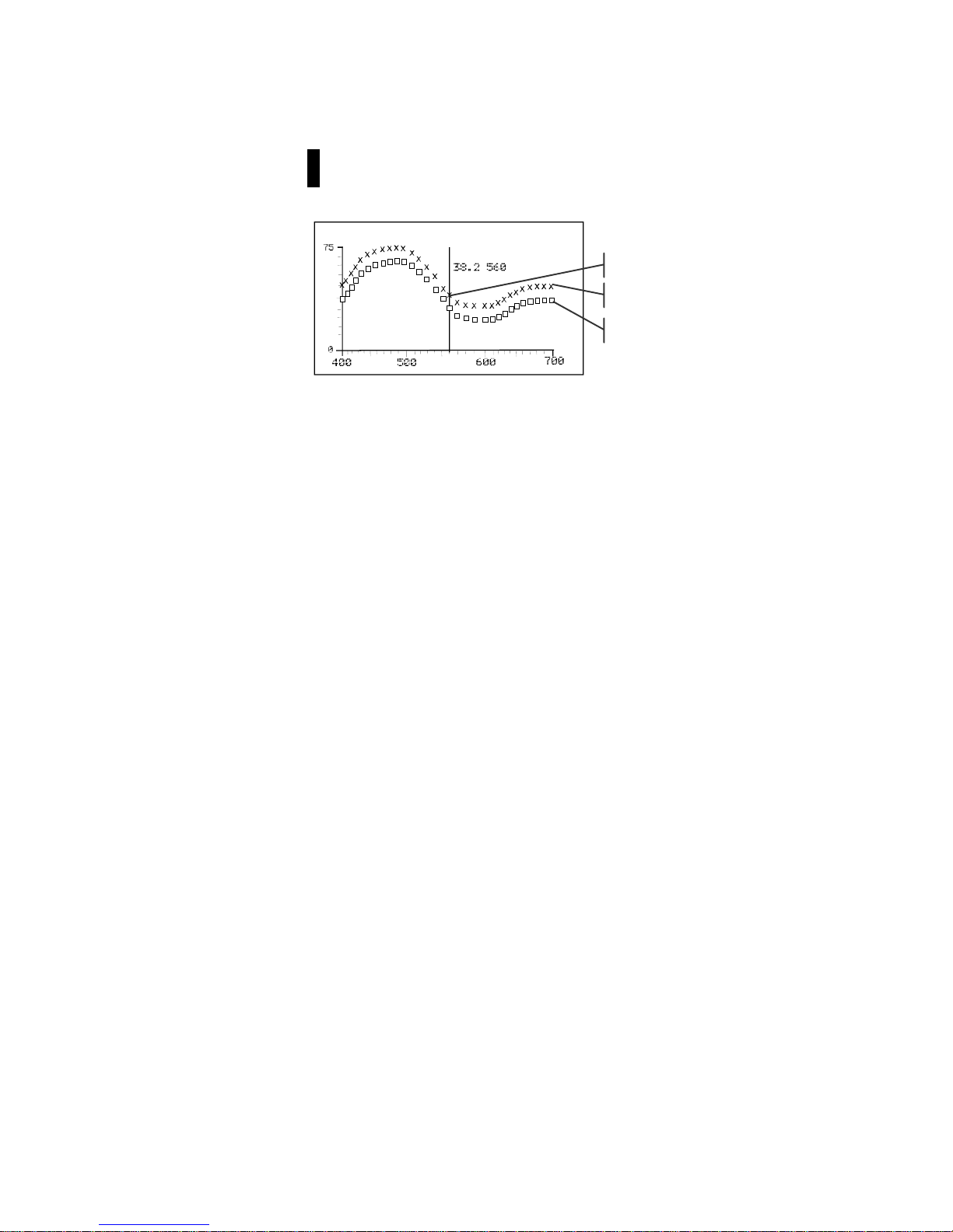
CHAPTER FIVE
5-22
NOTE: When averaging is used, all measurements must be completed
before the graph screen can be entered.
3. Repeatedly press the Tab Up key $ or Tab Down key @ to
view the data in 10 nm increments, along the reflectance
curve.
4. Press the Escape key ! to return the display to the main
data screen.
Refl Graph
37.5
Current point selected
Sample curve
Standard curve
Page 74
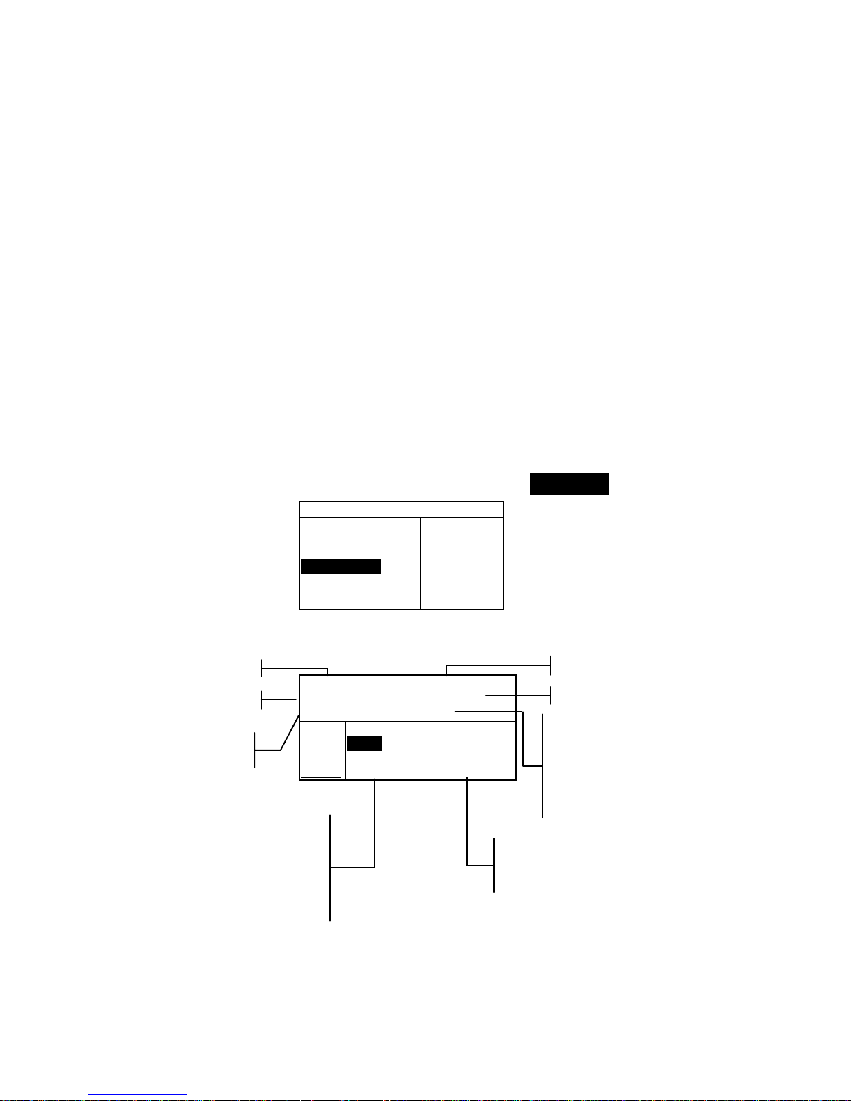
INSTRUMENT OPERATION MODES
5-23
Strength
The Strength function calculates the color strength of the
measured sample compared to the current standard. Strength is
calculated using the method selected in the instrument
configuration (Apparent, Chromatic, or Tristimulus). Once
measured, the color data can be calculated and displayed for
color at equivalent strength (@ 100%). The strength to achieve
minimum Delta E* can also be calculated and displayed.
Several operations available in Strength are identical to those
available in QA. Therefore, the discussion of these operations
is not repeated for Strength . For information covering Project
Selection, Standard Selection, Storage Operati on, Tag gin g
Operation, Pass/Fail Operation, Sample Tools, and Viewing the
Reflectance Graph, refer to the QA function.
To access the Strength function:
1. Use the Tab keys $@ to highlight Strength.
–MAIN MENU–
QA
Analyze
Compare
Strength
Opacity
↓
X—Rite
964
——————
XXXX
******
2. Press the Enter key # to access the Strength function.
Proj 1: PROJECT A
Std 1: STANDARD A
Sample: #1 8:50
L*a*b*
D65/10
....
.
.
.
...
ΔL* +1.00
Str = Δa* —0.26
93.7% Δb* —0.79
App ΔE* 1.30
Project Name
Standard Name
Project Location
Standard Location
This field always displays
<Last Meas> when samples
are not stored. When
samples are stored, a
sample # and time stamp is
displayed.
Accesses
Sample Tools
Sample difference values or
words appear indicating
color direction.
This area displays the
sample’s strength % and
method. If Chromatic is set,
a wavelength (i.e., 420λ)
appears indicating the
calculation wavelength.
Page 75

CHAPTER FIVE
5-24
Strength Measurement
The Strength function displays the color strength of the
measured sample. Difference data from the standard is also
displayed if difference is activated in configuration. When
strength is displayed for color at 100% or Strength @ Min ΔE,
the difference values automatically recalculate.
To perform a strength measurement:
1. Select project location (if used) as discussed in the QA
function.
2. Select the standard location if the auto standard selection is
not activated in configuration.
3. Measure the sample.
4. Use the Tab keys $@ to highlight Str = (if not already
highlighted).
Proj 1: PROJECT A
Std 1: STANDARD A
Sample: #1 8:50
L*a*b*
D65/10
....
.
.
.
...
ΔL* +1.00
Str = Δa* —0.26
93.7% Δb* —0.79
App ΔE* 1.30
5. Press the Enter key # to toggle to equivalent strength.
Proj 1: PROJECT A
Std 1: STANDARD A
Sample: #1 8:50
L*a*b*
D65/10
....
.
.
.
...
ΔL* +0.15
@ Str Δa* —0.20
= 100%
→ Δb* —0.56
ΔE* 0.61
Proj 1: PROJECT A
Std 1: STANDARD A
Sample: #1 8:50
L*a*b*
D65/10
....
.
.
.
...
ΔL* —0.73
≅ Str Δa* —0.14
@MinΔE→ Δb* —0.30
101% ΔE* 0.80
Color difference
predicted values with
equivalent strength
(at 100%)
Predicted @ 100%
Color Stren
g
th
Predicted @ MinΔE
Stren
g
th
Predicted strength to
achieve minimum
color values
Page 76
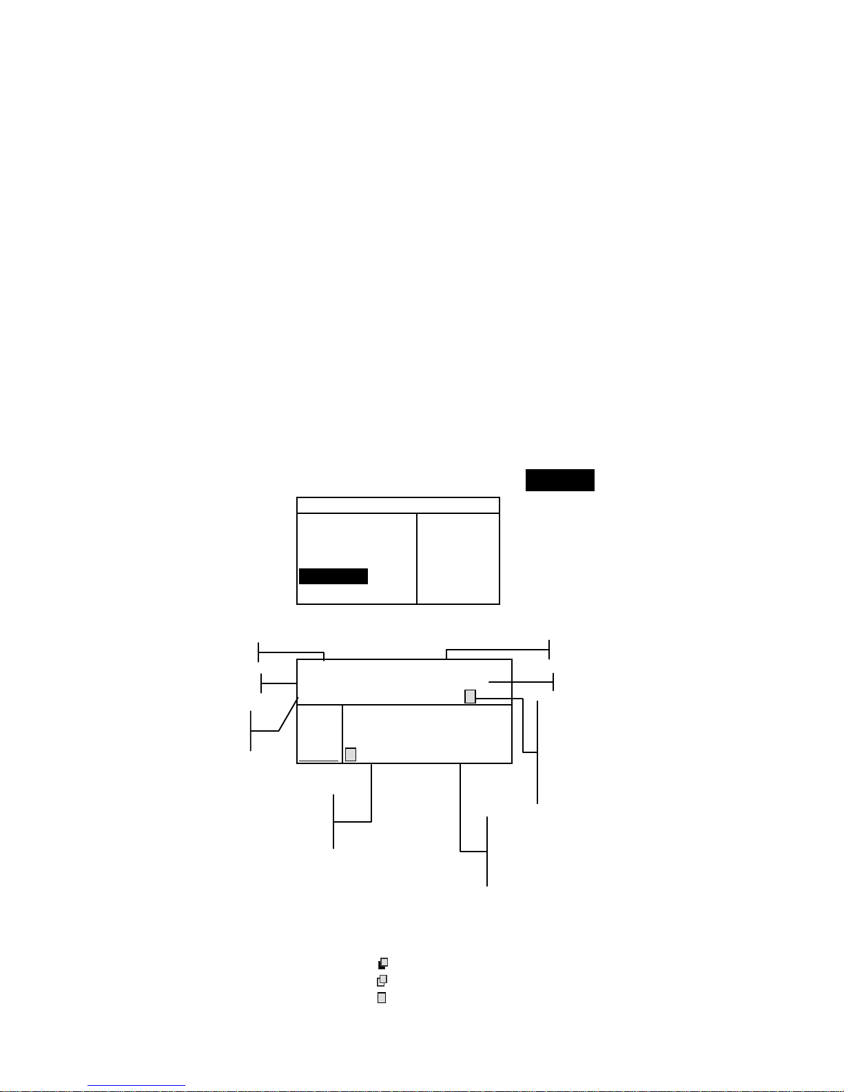
INSTRUMENT OPERATION MODES
5-25
Opacity
The Opacity function is used for making multiple measurement
calculations to determine Contrast Ratio or Percent Opacity.
Each measurement requires three readin gs ( over-black, overwhite, and a measurement of the white backing). The final data
can be stored and displayed either as over-white, over-black, or
color at full hide (equivalent color @ 100% opacity) as
determined by configuration settings.
Several operations available in Opacity function are identical to
those available in the QA function. Therefore, the discussion of
these operations is not repeated for Opacity. For information
covering Project Selection, Standard Selection, Storage Operation,
Tagging Operation, Pass/Fail Operation, Sample Tools, and
Viewing the Reflectance Graph, refer to QA function.
To access the Opacity function:
1. Use the Tab keys $@ to highlight Opacity.
–MAIN MENU–
QA
Analyze
Compare
Strength
Opacity
↓
X—Rite
962
——————
XXXX
******
2. Press the Enter key # to access the Opacity function.
Proj 1: PROJECT A
Std 1: STANDARD A
Sample: #1 8:50
L*a*b*
D65/10
....
.
.
.
...
ΔL* +1.00
Opacity Δa* —0.26
97.93% Δb* —0.79
@100%→ ΔE* 1.30
The opacity data type saved to the database is defined in the
Configuration mode. A symbol on the sample line indicates the
data display type saved (see below).
Over Black
Over White
Color at 100%
Project Name
Standard Name
Project Location
Standard Location
This field displays <Last
Meas> when samples are
not stored. When samples
are stored, a sample #, time
stamp, and data type symbol
are displayed.
Accesses
Sample Tools
Sample difference values or
words appear indicating
color direction compared to
the current standard.
This area displays the
sample’s opacity %
and data display type.
Page 77
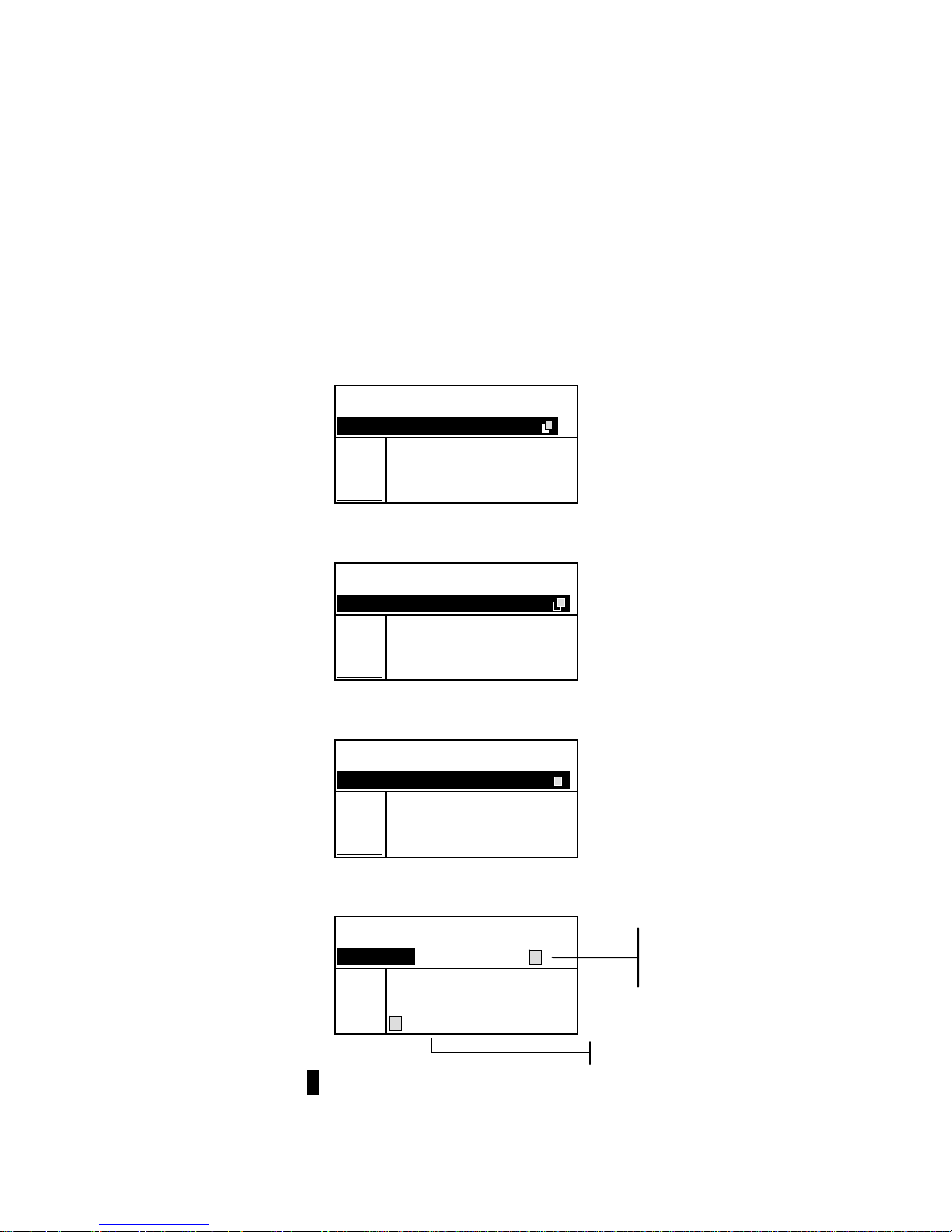
CHAPTER FIVE
5-26
Opacity Measurement
The Opacity function displays the percent opacity of a drawn
down sample on an opacity card. Color difference data is also
displayed if difference is activated in the configuration.
To perform an opacity measurement:
1. Select the project location and standard location (if
required) as discussed in the QA function.
2. Close the instrument to the shoe, then release to activate
the opacity measurement sequence.
Proj 1: PROJECT A
Std 1: STANDARD A
Measure over BLACK
L*a*b*
D65/10
....
.
.
.
...
3. Measure the sample over the black portion of the opacity
card. Release the instrument after data is displayed.
Proj 1: PROJECT A
Std 1: STANDARD A
Measure over WHITE __
L*a*b*
D65/10
....
.
.
.
...
L* 81.15
a* +4.50
b*+81.00
4. Measure the sample over the white portion of the opacity
card. Release the instrument after data is displayed.
Proj 1: PROJECT A
Std 1: STANDARD A
Measure white BACK __
L*a*b*
D65/10
....
.
.
.
...
L* 81.76
a* +6.17
b*+82.03
5. Measure the white backing of the opacity card. Release the
instrument after the opacity value is displayed.
Proj 1: PROJECT A
Std 1: STANDARD A
Sample: #1 8:50
L*a*b*
D65/10
....
.
.
.
...
ΔL* +1.00
Opacity Δa* —0.26
97.93% Δb* —0.79
@100%→ ΔE* 1.30
NOTE:. When data is stored, only one illum/obs is saved with the data.
Color at 100%
Symbol indicates
color at 100%
data type.
Page 78
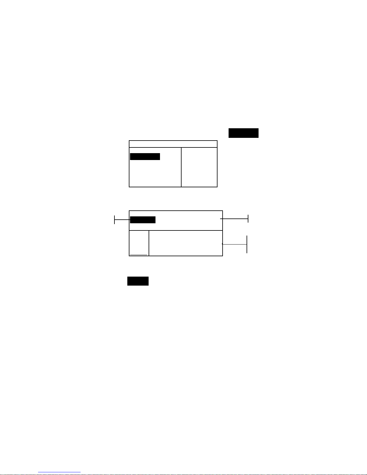
INSTRUMENT OPERATION MODES
5-27
Analyze
The Analyze function allows you to compare sample
measurements to stored standards. The resulting color data
(actual and difference) is not stored in the instrument. Measured
data can be automatically transmitted from the RS-232 port if
Auto Xmt is activated in the Instrument Configuration.
To access the Analyze function:
1. Use the Tab keys $@ to highlight Analyze.
–MAIN MENU–
QA
Analyze
Compare
Strength
Opacity
↓
X—Rite
964
——————
XXXX
******
2. Press the Enter key # to access the Analyze function. Data
from the last measurement taken is displayed.
Analyze
Std 1: STANDARD A
L*a*b*
D65/10
....
.
.
.
...
ΔL* –0.06
L* 33.85 Δa* —0.02
a* +5.55 Δb* +0.16
b* +9.77 ΔE* 0.17
3. If auto standard is not activated in configuration, select the
standard location by repeatedly pressing Enter key # with
Std # highlighted. To go to a specific standard, hold
down the Enter key # and select the standard from the
editor.
4. Measure the sample.
Standard Name
Standard Location
Sample measured
and difference data
Page 79
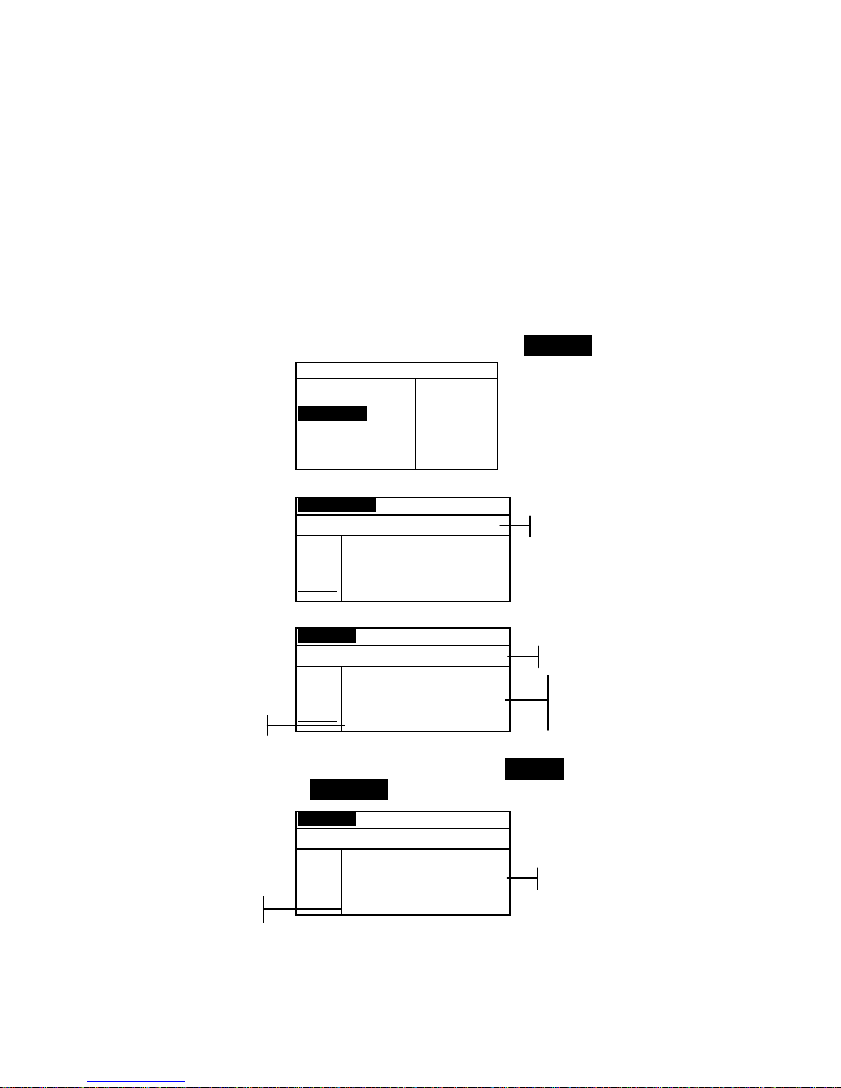
CHAPTER FIVE
5-28
Compare
The Compare function is a quick method for comparing
measurements without storing the data. After entering the
mode, the first measurement is set as the standard and each
measurement thereafter is compared to it. The standard can be
remeasured whenever desired. Measured data can be
automatically transmitted from the RS-232 port if Auto Xmt is
activated in the Instrument Configuration.
To access the Compare function:
1. Use the Tab keys $@ to highlight Compare.
–MAIN MENU–
QA
Analyze
Compare
Strength
Opacity
↓
X—Rite
964
——————
XXXX
******
2. Press the Enter key # to access the Compare function.
Standard Compare
<Measure Standard>
L*a*b*
D65/10
....
.
.
.
...
L* 0.00
a* 0.00
b* 0.00
3. Measure the standard to be used for comparison.
Sample Compare
<Measure Sample>
L*a*b*
D65/10
....
.
.
.
...
ΔL* +0.00
L* 81.17 Δa* —0.00
a* +6.39 Δb* +0.00
b*+83.05 ΔE* 0.00
4. Standard measurement data is displayed. Measure the sample
or press the Enter key # with Sample highlighted to toggle
to Standard. Another standard can then be measured.
Sample Compare
<Measure Sample>
L*a*b*
D65/10
....
.
.
.
...
ΔL* –0.08
L* 81.09 Δa* —0.00
a* +6.39 Δb* –1.08
b*+81.97 ΔE* 1.08
Measurement instruction
Difference Data
Sample Data
Difference data appears
as all zeros before
measuring a sample
Measurement instruction
Standard Data
Page 80
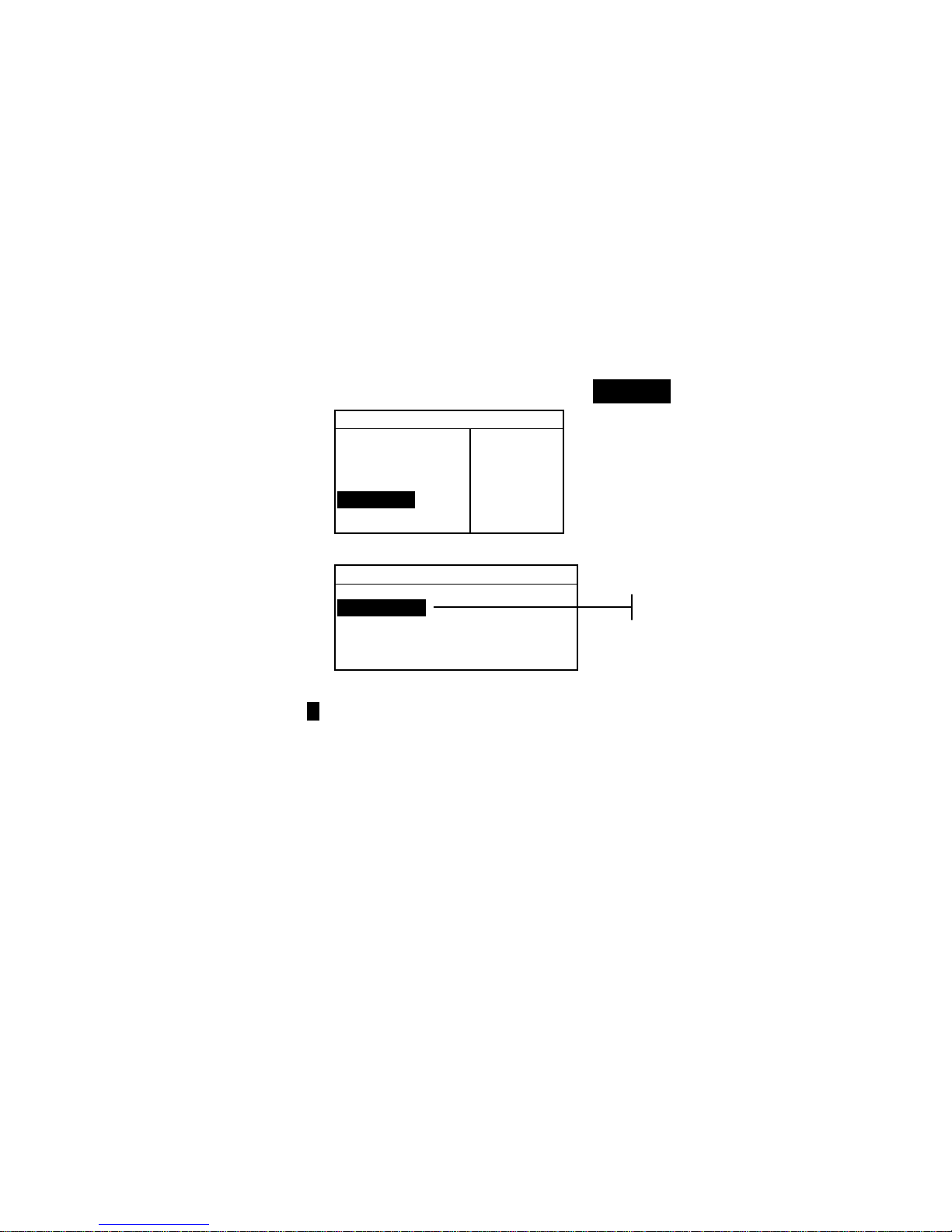
INSTRUMENT OPERATION MODES
5-29
Run Job (964 only)
The Run Job function is used to select a job sequence
downloaded from X-RiteColor® Master software program. A
typical job would display measurement prompts on the
instrument screen. The instrument can store a total of 10 jobs at
one time.
Refer to X-RiteColor® Master for specific information on jobs
and job operation.
To access the Run Job mode:
1. Use the Tab keys $@ to highlight Run Job.
–MAIN MENU–
↑
Calibrate
Standards
Projects
Run Job
Configuratio
X—Rite
964
——————
XXXX
******
2. Press the Enter key # to access the Pick Job mode.
Pick Job #
1: Job 1
2: Job 2
3: Job 3
4: Job 4
5: Job 5
3. Use the Tab keys $@ to highlight the desired job.
Note: <Empty> appears in the display when no jobs are available.
4. Press the Enter key # to activate job sequence.
A
vailable jobs
Page 81

Page 82

962/964
SPECTROPHOTOMETER
6-1
6. Service and General Maintenance
Repair Information 6-1
Cleaning the Instrument 6-1
Replacing the Battery Pack 6-3
Repair Information
The X-Rite® 962 and 964 instruments are covered by a oneyear limited warranty—excluding battery pack—and should be
referred to factory or authorized service center for repairs
within the warranty period. Attempts to make repairs within
this time frame may void the warranty.
X-Rite provides a factory repair service to their customers.
Because of the complexity of the circuitry, all repairs should be
referred to the factory or an authorized service center
(call: 1-888-826-3042).
X-Rite will repair any instrument past warranty. The customer
shall pay shipping cost to the factory or authorized service
center and repair cost. The instrument shall be submitted in the
original carton, as a complete unaltered unit.
Reading Lamp Replacement Information
Due to the circuit complexity and test equipment required, the
read lamp should only be replaced by X-Rite or an
authorized X-Rite Service Center.
The lamp is monitored for intensity, and failure warnings will
be displayed if a problem occurs.
Cleaning the Instrument
Your instrument requires very little maintenance to achieve
years of reliable operation. However, to protect your
investment and maintain reading accuracy, a few simple
cleaning procedures should be performed from time to time.
General Cleaning
The exterior of the instrument may be wiped clean with a cloth
dampened in water or mild cleaner whenever required.
NOTE: DO NOT use any solvents to clean the instrument; this causes
damage to the cover.
Page 83

CHAPTER SIX
6-2
Cleaning the Optics
The optics should be cleaned once a week in normal
environments, and more often in dirty or dusty environments.
Carefully lift the instrument and blow short bursts of clean, dry
air into the measurement aperture. This should remove any
accumulated dust in the optics area.
WARNING: DO NOT invert cans that use Freon as a propellant;
doing so could cause damage to the optics assembly.
Cleaning the Calibration Reference
The calibration reference consists of a ceramic disk for white
calibration measurements and a trap opening for black
calibration measurements.
The white ceramic disk can be cleaned periodically using a
mild soap and warm water solution, thoroughly rinsed with
warm water and wiped dry with a lint-free cloth. Do not use
solvents or cleaners of any kind.
The black trap portion of the reference should be cleaned with
clean, dry air from time to time to remove any dust or
contamination. The reference can be taken apart for easy
cleaning of the black trap by compressing the two locking tabs
on both sides of the case with your fingers, and separating the
two sections.
Make sure to store the calibration reference in a dry, dust free
area, away from direct exposure to light.
Locking Tab
White Disk
Locking Tab
Page 84
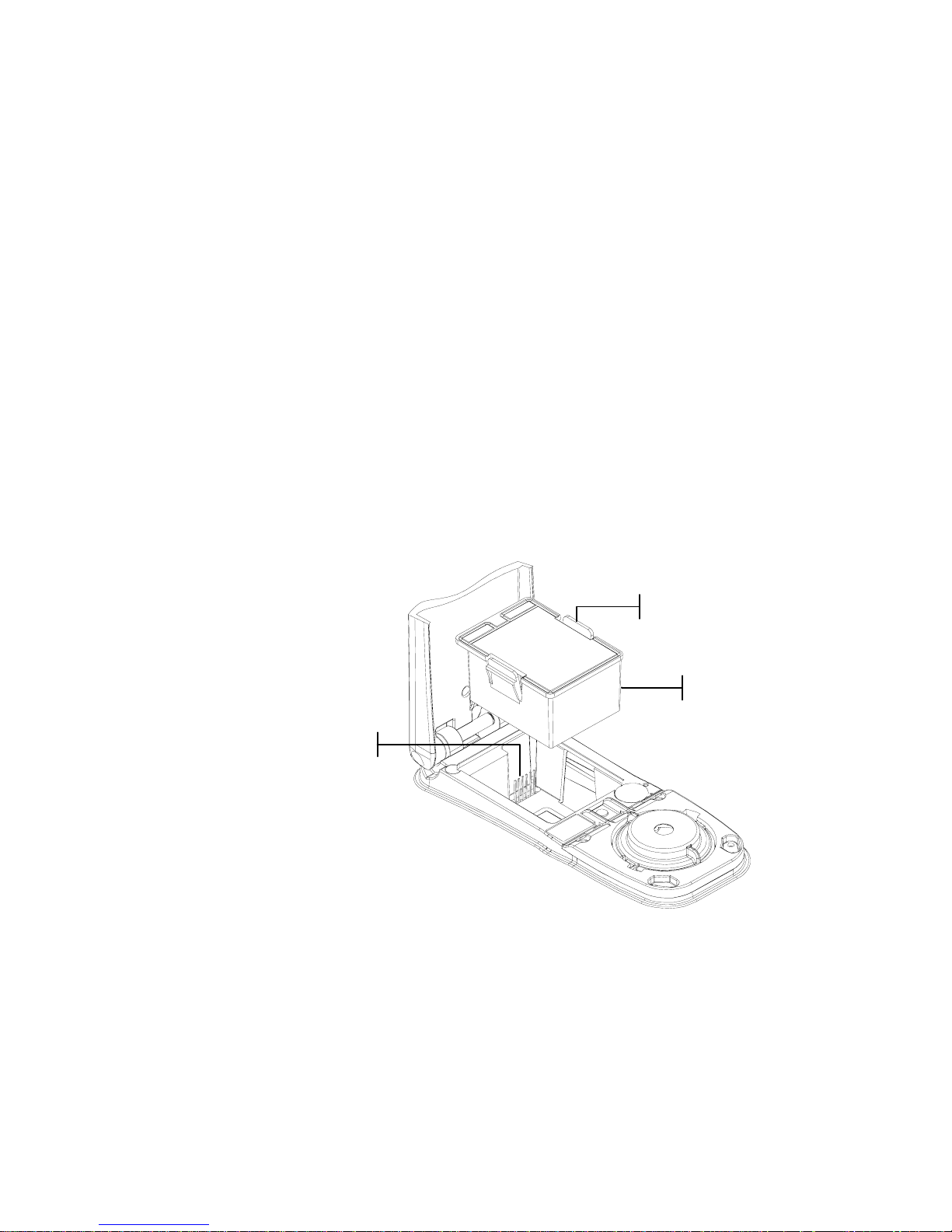
INSTRUMENT OPERATION MODES
6-3
Replacing the Battery Pack
1. Unplug the AC adapter and click the battery switch to Off.
2. Hold the shoe next to the instrument housing and lift
upward on the spring-loaded latch. Open the shoe
perpendicular to the instrument housing. Refer to
Unlatching the Instrument Shoe in Section One.
3. Carefully rotate the instrument over and rest it on its top.
4. Using your fingers, compre ss the two tabs located on both
sides of the battery pack and remove battery pack.
5. Slide a fresh battery pack into the compartment with the
battery connector facing down and to the back of the
instrument.
6. Press down on the pack until the connector is prop erly
seated and the tabs click into position.
Battery Connecto
r
Battery Pack
Pack Tabs
Page 85

CHAPTER SIX
6-4
Page 86

962/964
SPECTROPHOTOMETER
7-1
7. Appendices
Instrument Specifications 7-1
Error Messages 7-2
Parts List and Packaging 7-3
Changing the Aperture 7-5
Instrument Specifications
Measurement Geometrics 0/45°, DRS spectral engine, choice of optical
aperture: 4mm, 8mm, and 16mm
Light Source Gas-filled tungsten lamp
Illuminant Types A, C, D50, D65, D75, F2, F7, F11, & F12
Standard Observers 2° & 10°
Receiver Blue-enhanced silicon photodiodes
Spectral Range 400 nm – 700 nm
Spectral Interval 10 nm – measured, 10 nm – output
Storage 1,024 standards with tolerances, 2,000 sam ples
Measurement Range 0 to 200% reflectance
Measuring Time Approx. 2 seconds
Inter-Instrument Agreement (962) 0.20 ΔE*
ab
, based on avg. of 12 BCRA series II tiles
0.40 ΔE*
ab
max. on any tile
Short-Term Repeatability (962 ) 0.1 ΔE*
ab
max. on white ceramic, standard deviation
Inter-Instrument Agreement (964) 0.15 ΔE*
ab
, based on avg. of 12 BCRA series II tiles
0.30 ΔE*
ab
max. on any tile
Short-Term Repeatability (964 ) 0.05 ΔE*
ab
max. on white ceramic, standard deviation
Lamp Life Approx. 500,000 measurements
Power Supply Removable (Ni-metal hydride) battery pack;
7.2 VDC rated @ 1450 mAh.
AC Adapter Requirements 90-130 VAC, 50-60 Hz, 15 W max
Charge Time Approx. 4 hours – 100% capacity
Measurements Per Charge 1,000 measurements typical
Data Interface Patented bi-directiona l RS-232, 300-57,600 ba ud
Display 128 x 256 pixel grap hical LCD
Operating Temperature Range 50° to 104°F (10° to 40°C)
85% relative humidity maximum (non-condensing)
Storage Temperature Range -4° to 122°F (-20° to 50°C)
Dimensions 4.3”H (10.9 cm) 3.3”W (8.4 cm) 7.7”L (19.6 cm)
Weight 2.4 lbs. (1.1 kg)
Accessories Provided Calibration Standard, Manual,
AC Adapter, Carrying Case
Usage Indoor only
Altitude 2000 m
Pollution Degree 2
Overvoltage Category II
X-Rite reference standards are traceable to the National Institute of Standards and Technology through
Munsell Color Science Laboratory RIT.
Specifications and design subject to change without notice.
Page 87

CHAPTER SEVEN
7-2
Error Messages
Errors encountered during a measurement are displayed on the
instrument screen. All errors are accompanied by a long beep
and flashing yellow light. The error message is cleared from the
instrument screen by pressing the Enter key # .
Displayed Errors: Reason
Measurement was
aborted by user
Displays with an incomplete measurement or
calibration. Instrument was released too soon.
Calibration has
timed out
The calibration interval time set in the
configuration has been reached. Calibration is now
required.
Calibration
required
Displays anytime the instrument requires a
calibration.
Calibration has
failed
Calibration failed. Make sure the instrument is
properly positioned on the reference.
Black cal failed
A measurement change was detected from previous
measurements. Re-measure black trap.
Was white cal
plaque measured
Yes No
The instrument wants to verify that the white cal
reference was measured. Press Yes if white cal was
measured. Press No if white cal was not measured
and measure white cal.
The battery is
getting low
This warning appears when the battery falls below
approximately 25% of full charge. Measurements
are still possible, but the battery should be charged
soon.
Batteries are
dead
Displays when not enough battery power remains
to take measurement. The current measurement is
aborted.
Batteries are
missing
The battery pack is not installed. Instrument will
not allow any measurements.
Incorrect
Charger Voltage
Wrong charger is connected or charger is bad.
The battery is
over–charged
The battery pack is too hot. Remove the battery
pack and let it cool.
Lamp is getting
weak, replace
soon
Reading lamp is at 50% strength or less from its
original intensity. Measurements are still possible
but the lamp should be replaced soon.
Transmission in
Progress
A measurement was attempted during a data
transmission from the I./O port. Wait until
transmission is completed before measuring.
Page 88
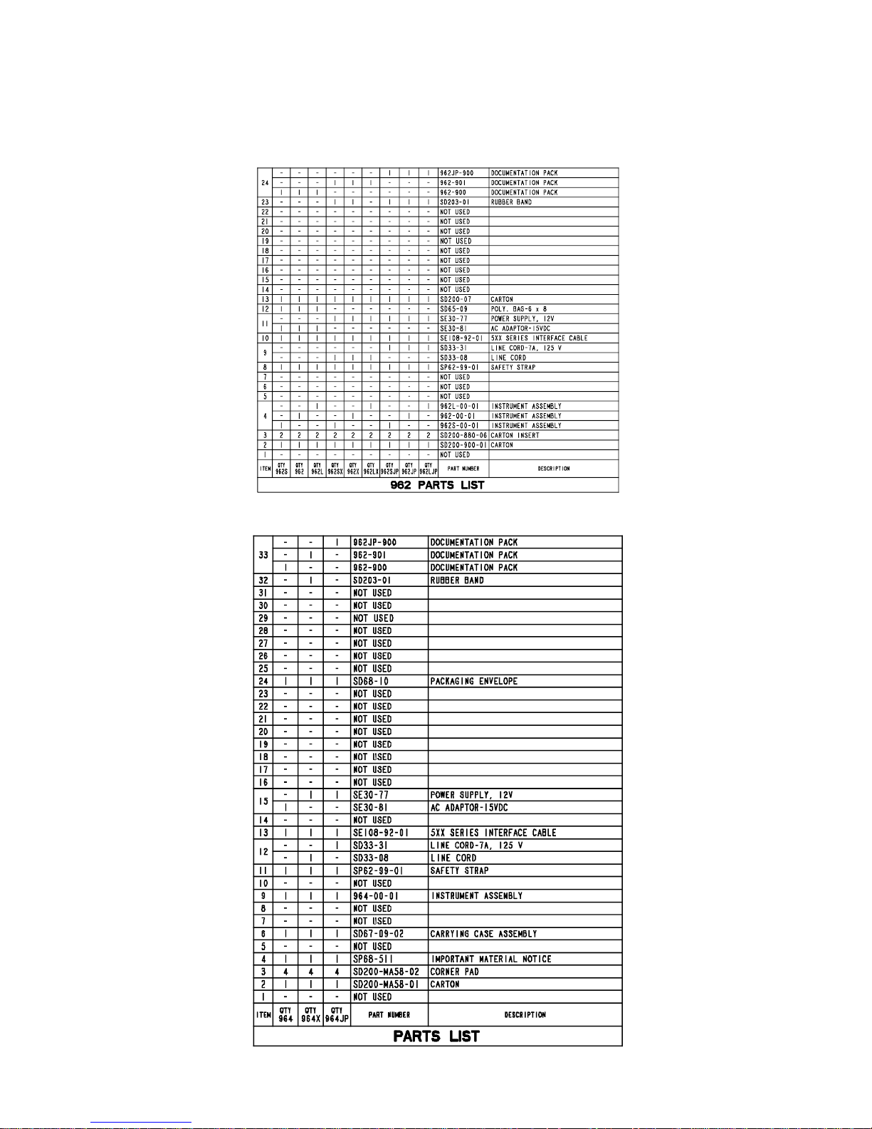
APPENDICES
7-3
Parts List (962)
Parts List (964)
Page 89

CHAPTER SEVEN
7-4
Packaging (962)
Page 90

APPENDICES
7-5
Packaging (964)
Page 91

CHAPTER SEVEN
7-6
Changing the Aperture
NOTE: The 964 instrument includes all three apertures.
The instrument was designed to allow you to quickly change
the aperture and target window. X-Rite provides three aperture
sizes especially designed for the instrument. Available sizes:
4mm, 8mm and 16mm.
Refer to the next page for illustrations.
To change the aperture size:
1. Unplug the AC adapter and click the battery switch to Off.
2. Hold the shoe next to the instrument housing and lift
upward on the spring-loaded latch. Open the shoe
perpendicular to the instrument housing. Refer to
Unlatching the Instrument Shoe in Section One.
3. Carefully rotate the instrument over and rest it on its top.
4. Using your fingers, rotate th e sensor nose to the left
(counter-clockwise) until it stops.
5. Carefully remove the sensor nose by lifting upward s and
set aside.
6. Position the appropriate end of the ap erture wrench on the
existing aperture and remove by turning to the left
(counter-clockwise) until it is free. Set existing aperture
aside.
CAUTION: Extreme care should be taken not to contaminate the
optics with any dust or dirt when installing the new aperture.
7. Align new aperture over opening in optics and secure by
using the appropriate end of the aperture wrench.
8. Position corresponding sensor nose over the optics opening
in the bottom housing and rotate to the right (clockwise)
until it stops.
9. Using your fingers, press the target window out from the
topside of the shoe. Press against the ring and not the clear
window.
10. Note the alignment of the new window and snap it into
place from the bottom side of the shoe.
11. The aperture setting in the instrument must now be set to
match the new size. Refer to the following procedure.
Page 92
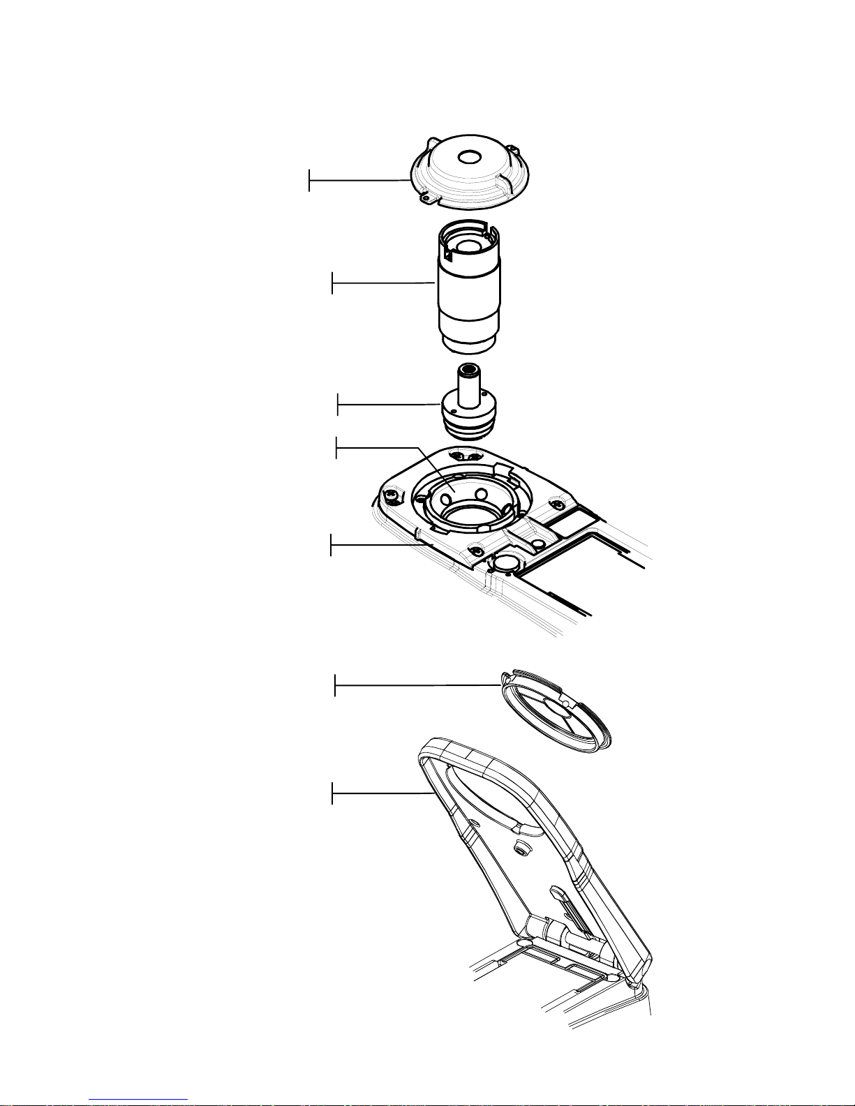
APPENDICES
7-7
Sensor Nose
Aperture Wrench
Aperture
Optics
Target Window
Shoe
Bottom Housing
Page 93
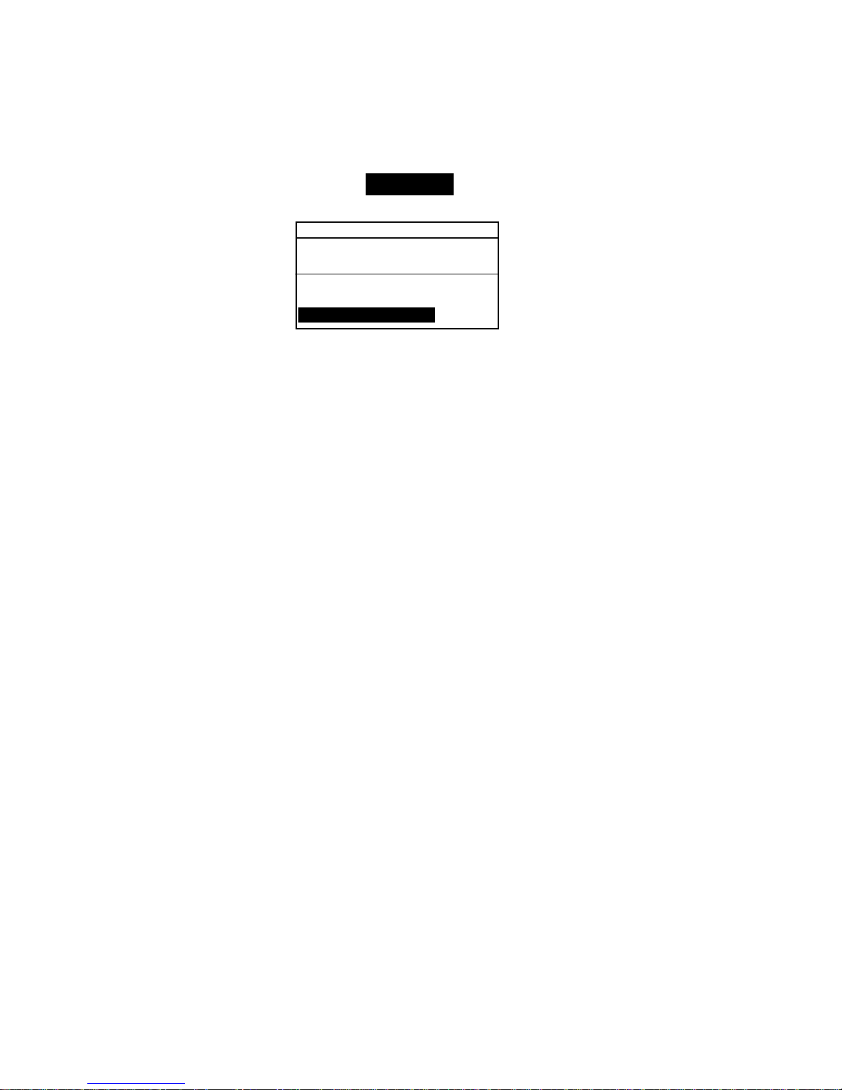
CHAPTER SEVEN
7-8
Changing the Aperture Setting
1. At the Main Menu, use the Tab Up $ or Tab Down @ key to
highlight Calibrate. Press the Enter key # to access the
Calibration Menu.
CALIBRATION
< Measure White Ref>
Status: Cal time up
S/N: ******
Ap Size: 8.0mm
2. Press the Enter key # again to access the Choose
Aperture
editor.
3. Use the Tab Up $ or Tab Down @ key to highlight the new
aperture size. Press the Enter key # to save selection and
exit back to the Calibration menu.
4. Calibrate the instrument to the new aperture size (refer to
Calibration, Section Three).
Page 94

Corporate Headquarters - USA
4300 44th Street SE
Grand Rapids, Michigan 49512
Phone 1 800 248 9748 or 1 616 803 2100
Fax 1 800 292 4437 or 1 616 803 2705
Corporate Headquarters - Europe
Althardstrasse 70
8105 Regensdorf
Switzerland
Phone (+41) 44 842 24 00
Fax (+41) 44 842 22 22
Corporate Headquarters - Asia
Room 808-810
Kornhill Metro Tower, 1 Kornhill Road
Quarry Bay, Hong Kong
Phone (+852) 2 568 6283
Fax (+852) 2 885 8610
Please visit www.xrite.com
for a local office near you.
P/N 962-500 Rev. E
 Loading...